A Large-Deformation Gradient Damage Model for Single Crystals Based on Microdamage Theory


1
Department of Mechanical Engineering, Atilim University, Ankara 06830, Turkey
2
Supmeca-Paris, Mechanical and Manufacturing Engineering School, 93400 Saint-Ouen, France
*
Authors to whom correspondence should be addressed.
Appl. Sci. 2020, 10(24), 9142; https://0-doi-org.brum.beds.ac.uk/10.3390/app10249142
Submission received: 25 November 2020
/
Revised: 12 December 2020
/
Accepted: 14 December 2020
/
Published: 21 December 2020
(This article belongs to the Special Issue Latest Trends in Physics and Engineering Mathematics: Theory and Application)
Abstract
:This work aims at the unification of the thermodynamically consistent representation of the micromorphic theory and the microdamage approach for the purpose of modeling crack growth and damage regularization in crystalline solids. In contrast to the thermodynamical representation of the microdamage theory, micromorphic contribution to flow resistance is defined in a dual fashion as energetic and dissipative in character, in order to bring certain clarity and consistency to the modeling aspects. The approach is further extended for large deformations and numerically implemented in a commercial finite element software. Specific numerical model problems are presented in order to demonstrate the ability of the approach to regularize anisotropic damage fields for large deformations and eliminate mesh dependency.
1. Introduction
Highly anisotropic behavior of single crystals necessitates the consideration of microstructurally motivated life time estimation models. Considering the general use of single crystals in complex geometries under harsh environments such as turbine blades, modeling of crack growth due to the coupling of plasticity and damage becomes essential [1,2]. The chosen constitutive model should satisfactorily demonstrate the extremely anisotropic and nonlinear behavior of single crystals under severe thermomechanical loading conditions. There are many modeling attempts in the literature which associate damage localization to crystallographic planes and inelastic deformations [3,4,5].
Conventional rate-independent strain based approaches do not effectively model the localization of deformation due to damage within a finite thickness, since they lack an intrinsic length scale. A theory which includes a material length scale is necessary for modeling such an inherently size-dependent phenomenon. Earliest attempts of modeling introducing a length scale are in the plasticity theory [6,7]. The proposed approach is further extended and numerically implemented in several works [8,9,10] and established as so-called gradient plasticity theories with the remarkable works by Engelen, Peerlings, Geers and Forest [11,12,13,14,15]. Based on principle of virtual power, a thermodynamically consistent formulation considering nonlocal terms energetic, i.e., not dissipative in character, is presented by Gurtin and Anand [16] and a micromorphic version of the theory is also demonstrated in Anand et al. [17]. In the same spirit, there are many regularization attempts in the literature for strain softening behavior due to damage [18]. Such a micromorphic continuum based regularization technique has also been proposed for single crystals in order to eliminate the mesh-dependency problem of the results of such simulations of finite elements by Aslan et al. [19]. However, those attempts exclude the energetic nature of the nonlocal terms.
Our main effort in this paper is to demonstrate a detailed development of the gradient damage model developed by Aslan and Forest for single crystals under large deformations [18], in parallel with the thermodynamical framework presented in [17]. For that purpose, first of all, the micromorphic damage model which introduces several crystallographic damage mechanisms is demonstrated in Section 2 and the emphasis is placed on the presentation of thermodynamical consistency of the model and identification of the dissipative or energetic character of the gradient variables which is presented in Section 3. The constitutive equations are presented in detail in Section 4 and a specialized modeling case is scrutinized in Section 5.
The second goal of this paper is to use our theory to report on several numerical simulation outcomes generated from model problems. The proposed theory is implemented for the commercial finite element software Abaqus/Standard by implementing a user element subroutine (UEL). In addition to the standart displacement degrees of freedom, a microdamage variable is introduced as an additional degree of freedom. The implementation is based on a standard four-node isoparametric element on the interpolated fields with continuity. Representative numerical examples that illustrate the capacity of the theory and its implementation to damage softening response which results in intense localization are provided together with discussions in Section 6.
2. Microdamage Model for Single Crystals
2.1. Basic Kinematics
Considering a body in the reference configuration represented by is mapped to the spatial point at time t, the motion of the body is represented by the smooth function . Accordingly, the deformation gradient, the velocity and the velocity gradient are given by
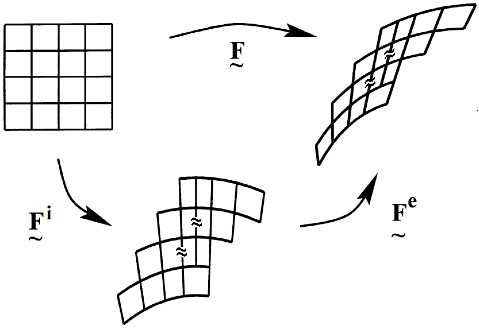
Following the The Kröner’s decomposition of the deformation gradient [20], the plastic deformation and damage in a crystal is represented in the inelastic distortion and accordingly the decomposition takes the following form:
where represents the rotation and stretch as elastic distortion and is the inelastic distortion capturing the plasticity and damage in the crystal. Figure 1 represents such a deformation for initial and final configurations.
However, for the sake of simplicity and the clarity of the proposed theory, the plastic part of the inelastic distortion is neglected throughout this work. Then the deformation gradient simply reads
represents the local inelastic deformation due to damage generated in the material and invariant under a change in frame. In this framework, the velocity gradient can be decomposed in the following form:
where
volumetric contribution to elastic and inelastic deformation is defined as
Considering the right polar decomposition of the elastic distortion
in terms of the right stretch tensor and the rotation tensor . The right elastic Cauchy-Green tensor and the stretch tensor are defined as
Hencky strain [21] is chosen as a strain measure due to its good agreement with the mechanical response of a wide class of materials [22,23].
The elastic and inelastic spin and stretching tensors are
Assuming irrotational damage evolution, i.e.,
The inelastic deformation gradient rate becomes
The damage stretching tensor is defined as
where is the damage rates initiated at each damage system which is a scalar internal variable and is the damage flow direction tensor. Finally, the scalar damage rate takes the following form
2.2. Micromorphic Variable χd
Inspiring from the work of Forest (2009), is defined as the micromorphic counterpart for the damage variable d, for the purpose of mathematical regularization as an additional kinematical degree of freedom. Note that is a positive valued scalar variable which constitutes a subset of micromorphic continuum specifically termed as microdamage continuum by Aslan and Forest (2009). Moreover, the calculation of its gradient numerically comes at ease, since is defined as a degree of freedom. In order to further develop our theory based on the principle of virtual power, the power expended over the rate of each microvariable is defined as follows:
The power over is expended by the microscopic stress π, is expended by the scalar microscopic stress , is expended by the microscopic stress vector , and is expended by the microscopic traction at the boundary.
3. Principle of Virtual Power
In light of the definitions provided in Section 2.2, neglecting the inertial terms and assuming that the variation of any independent variable will cause an energy change in the system, external and internal power densities for any given part P are defined as follows
where
and is the 1st Piola-Kirchhoff stress tensor. Principle of virtual power dictates the balance of external and internal powers for any given part P and for all generalized virtual rates
considering and and applying divergence theorem leads to the macroscopic force balance and the traction condition
Considering and , choosing an arbitrary field and applying divergence theorem leads to the microscopic force balance and the traction condition
Following the work of Anand et al. [19], local imbalance of energy is formalized as
where stands for the free energy per unit volume and is introduced into the Quation (24) as
where
Finally, dissipation density reads
4. Constitutive Equations
Before the presentation of the constitutive equations, several stress measures to be used in the model need to be introduced.
The Mandel stress is defined by
Accordingly, the second Piola stress reads
Then, the Cauchy stress takes the following form
The first Piola stress is expressed as
The free energy is primarily defined as:
and from the normality, the energetic state relations can be derived as
Introducing the state relations into the dissipation density defined by Equation (27), the dissipation inequality reads:
Therefore, the dissipative terms can simply be defined as:
Finally, the dissipation inequality takes its final form as:
5. Specialization of the Constitutive Equations
Considering the crystallographic structure of a single crystal, the damage evolution is formalized as an addition of each damage system such as:
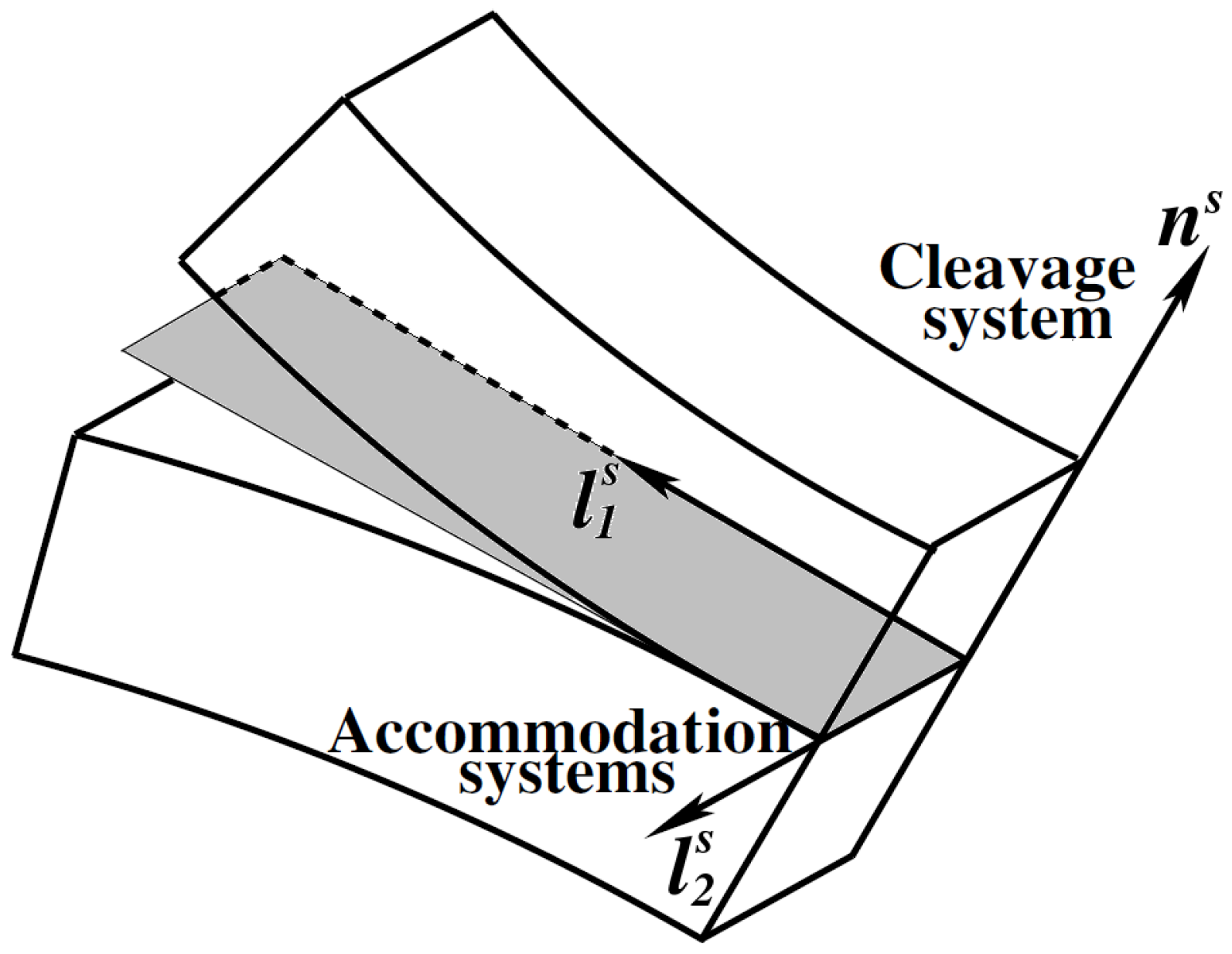
For three mode of fracture, damage evolution is calculated separately as , and the number of damage planes is determined from a given crystal structure. The opening of crystallographic planes with the normal vector can be defined as cleavage damage in the system and once cleavage has started, other damage systems are allowed to initiate for the inplane accommodation along orthogonal directions and , (Figure 2). Three damage criteria are associated to one opening and two accommodation systems:
where Y is the damage threshold and the scalar damage is simply the accumulation of damage generated in all systems.
The correspond equivalent stresses projected on to the damage system takes the form:
For this specific model, the free energy function is taken as a quadratic potential of elastic strain, , damage, d, microdamage, and its gradient,
where and are positive material constants. Assuming
Considering the damage criterion:
microscopic stress reads the following:
Recalling the constitutive relation for the microstress , the damage threshold function also becomes:
Further, recalling Equation (22), the microscopic force balance takes the from of Helmholtz equation which is postulated as implicit gradient theory for plasticity and damage [11,13,14], where the generalized stresses and are not explicitly introduced and the microvariables are defined as nonlocal variables.
which yields into the Helmholtz equation:
Note that the term in Equation (46) introduces an energetic coupling between d and its micromorphic counterpart χd, as it is performed in the classical micromorphic theory. Such a penalization necessitates a relatively high coupling modulus, B and the same energetic term also appears in Equation (48) which also serves as a flow rule for d. In the classical micromorphic theory such an energetic coupling is necessary since the elastic strain tensor is coupled with its higher order counterpart and the enrichment is always active even though the behavior is elastic. However, if the same procedure is applied to an internal variable which is dissipative in nature like d, an energetic penalization becomes unnecessary and also brings certain complexity, especially for softening materials. A bulky energetic term in the microforce balance like cannot contribute to the total dissipation; therefore, plastic softening is always limited by the stored energy through that term. Moreover, for an anisothermal theory, such an energy stored in the body cannot be clearly associated to a physical process in a standard material. In order to tackle that problem, an alternative set of moduli need to be introduced.
In the alternative approach the penalization is not energetic; therefore, coupling modulus, B, does not take place in the free energy function. However, the quadratic coupling between the scalar microvariable and its macroscopic counterpart is preserved:
where is a unit elastic modulus which converts unit strain into unit energy and is equivalent to of the conventional approach. Note that in this framework the higher order terms and are very small compared to the standard elasticity terms, thus, the energy stored through higher order continuum can be ignored. Accordingly, the energetic terms become:
and the generalized balance law takes the form:
An important observation from Equation (57) is the Laplacian form constructed in the equation provides regularized solutions only for the microvariable χd and d acts only as a source term. Therefore, in order to attain a similar solution on d, a dissipative penalization is introduced in the microforce balance, such as:
Considering the stress units in Pascal, for the majority of mechanical problems, is in the order of MPa and the B is a penalization constant in the order of elastic moduli. For a high value of B, a satisfactory solution for the local integration is possible only if d follows χd, otherwise the iterative values of overshoots the elastic trial stresses and the microforce balance will be violated. In that sense B is selected according to the desired difference between d and χd. Therefore, the selection criteria for the parameter B is more clear in that context and the energetic term can always be ignored since .
6. Numerical Results and Discussion
The model is implemented into a special user element subroutine so-called UEL in ABAQUS software, where the software is used solely as a solver and a visualizer. For the plane strain analysis, 2D four noded quadrilateral elements with bilinear shape functions are used. Microdamage variable is implemented as an extra degree of freedom, in addition to the standard displacements ( and ). The parameters used in the simulations are provided in Table 1.
6.1. Analysis of a 1D Bar
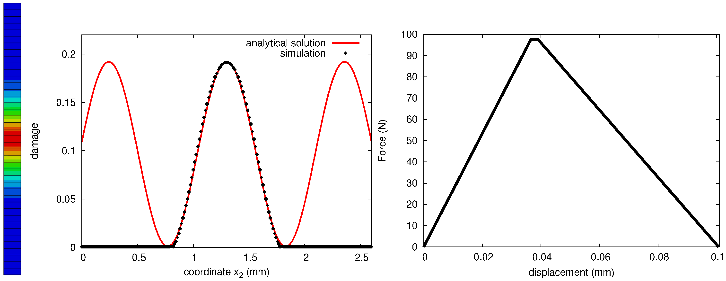
The regularization of a localized deformation with the proposed approach is demonstrated in a numerical model problem, where a bar with a length of 2.5 mm under tension is studied (Figure 3). An opening plane, normal to the direction of the bar is defined and at the center element, an initial defect is introduced where the damage threshold value is slightly reduced. Considering a rate independent damage evolution with linear isotropic softening and only active for opening mode, a microforce balance and the generalized balance law for the alternative case take the following form:
where is equivalent tensile stress, H is the softening modulus and is the initial material resistance. Using Equation (52) one can rewrite Equation (59) as follows:
Note that for a 1D problem, Equation (63) is a second order homogeneous differential equation with a general form:
where
which provides two types of solution depending on the sign of
Note that for a softening problem (providing ) the solution is sinusoidal an the wave length reads
6.2. Analysis of a 2D Single Crystal Block
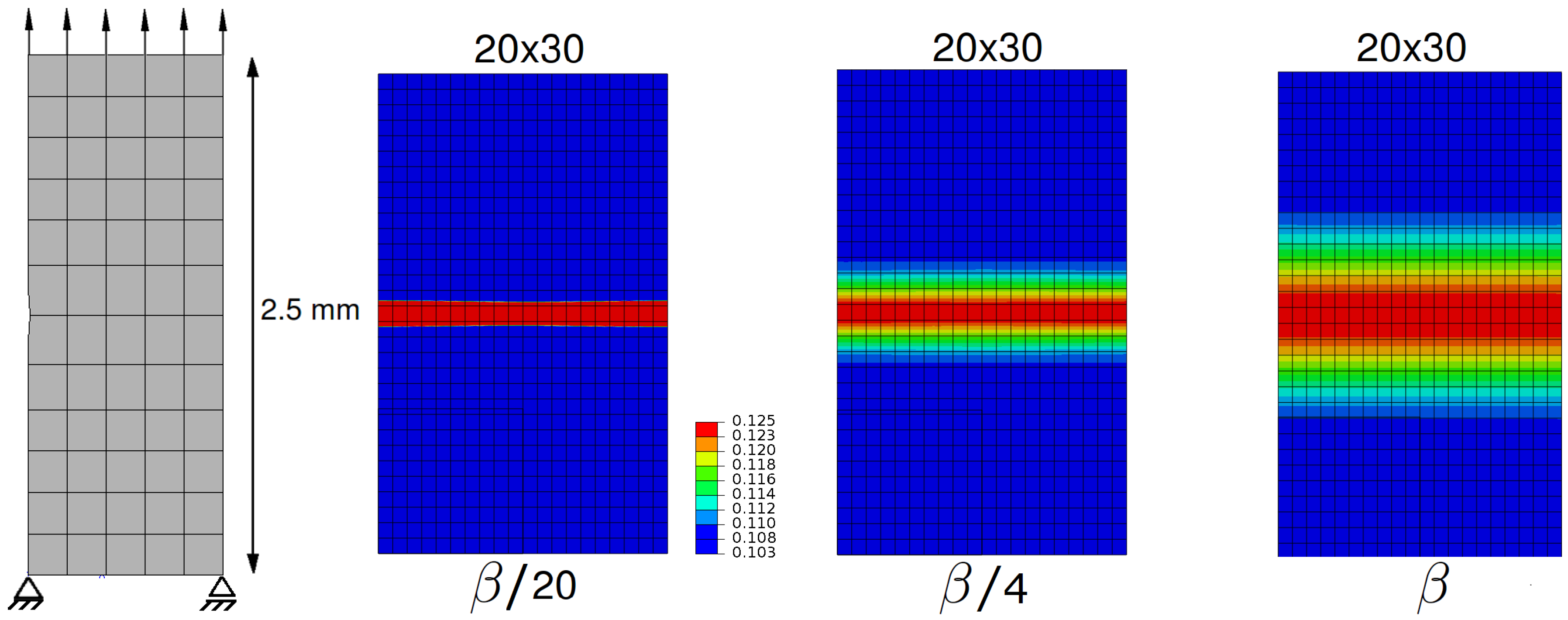
As a 2D example, a plate representing a 2D single crystal block under uniaxial tension with a horizontal cleavage plane is investigated (Figure 4). The localization is triggered with an initial geometric defect on the left edge and the cleavage plane is kept on the horizontal axis. The wave length of the localisation band is manipulated by the varying values . FEA results show that localization path is well in line with the cleavage plane and the localized deformation is captured with in a band whose size is mainly controlled by the length scale l defined in Equation (68).
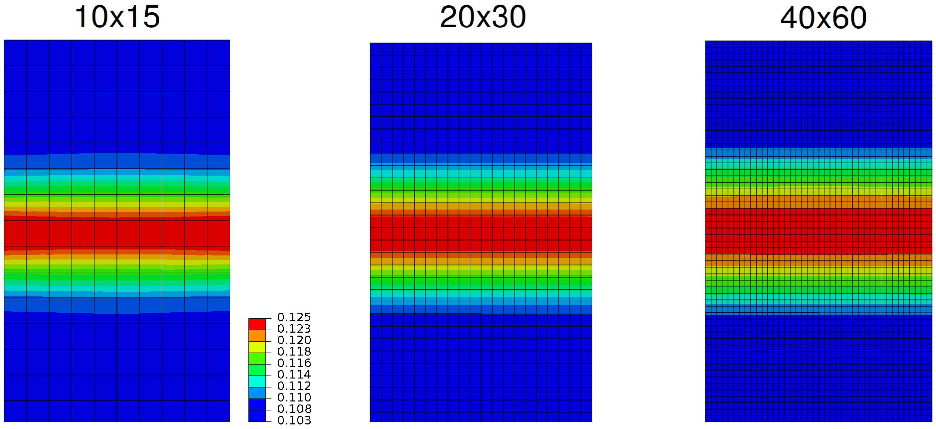
Figure 5 demonstrates the mesh independency of the results for a given damage plane with a constant parameter set with varying mesh densities. Results clearly show the successful regularization and mesh independency of the approach.
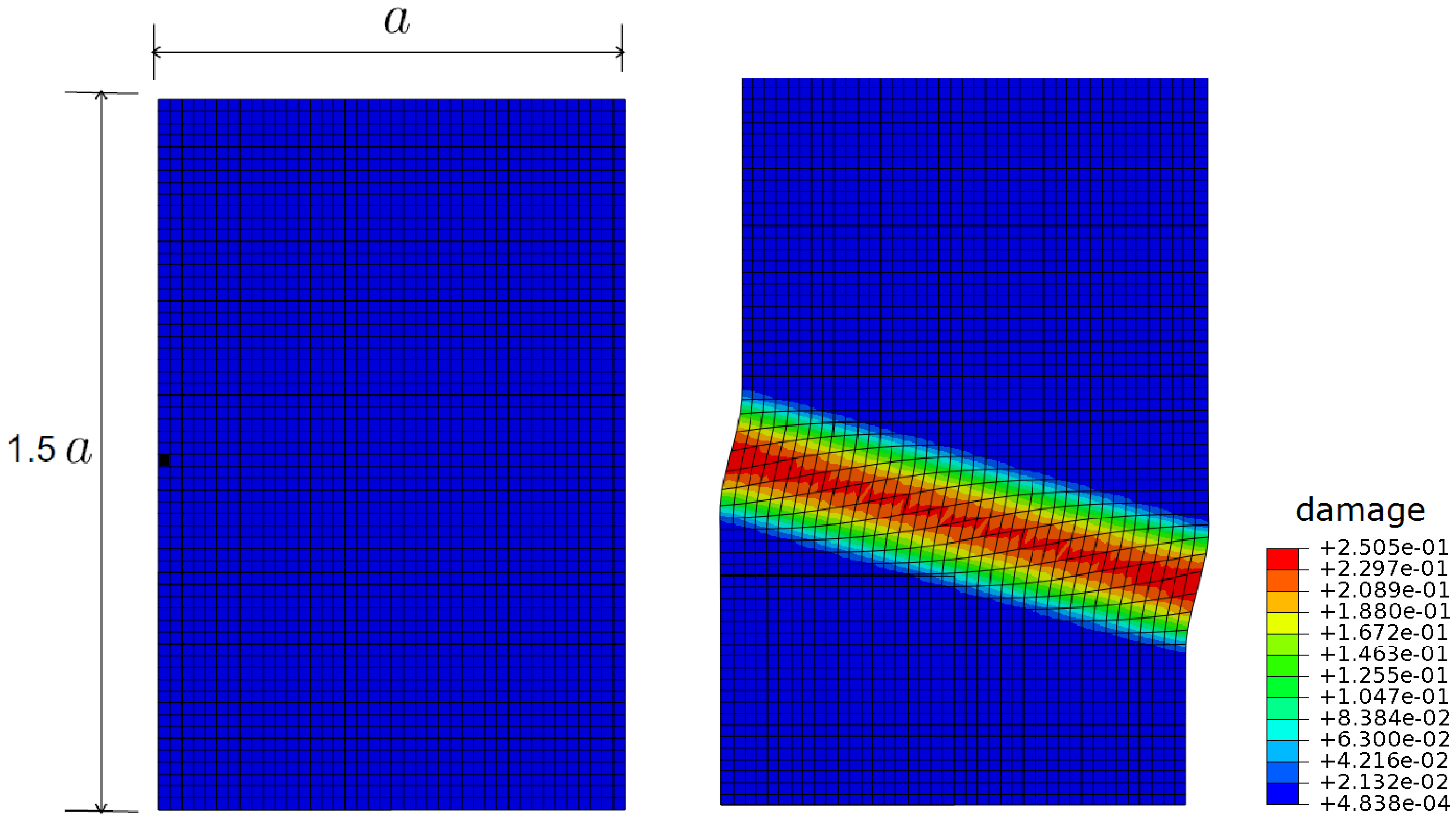
In order to demonstrate the regularized damage accumulation on a rotated plane, a 2D block with a cleavage plane tilted 25 degrees from the horizontal axis is analyzed under tension with a central defect. Analysis results show that the localization band is perfectly placed on the predefined rotated cleavage plane and the size of the band is kept constant throughout the crack as expected (Figure 6).
7. Concluding Remarks
In this work, we have made an attempt to unify the thermodynamically consistent representation of the micromorphic theory presented in the previous work [17] and the microdamage approach proposed by Aslan and Forest [18] for the purpose of modeling crack growth and damage regularization in crystalline solids. It has been shown that the proposed approach is suitable for large deformations and can conveniently be implemented for finite element analysis.
Our analytical effort also demonstrates that the characteristic solution which captures the intrinsic length scale for the localization band can also be achieved by introducing a negligible energetic term. That modification enables the material to undergo a fully damaged state where the equivalent stress reads zero and naturally eliminates the problem of energetic resistance against softening, observed in conventional strain gradient approaches.
Author Contributions
Conceptualization, O.A. and E.B.; Methodology, O.A.; Project administration, E.B.; Writing—review and editing, O.A. and E.B. All authors have read and agreed to the published version of the manuscript.
Funding
This research received no external funding.
Conflicts of Interest
The authors declare no conflict of interest.
References
- Aslan, O.; Quilici, S.; Forest, S. Numerical modeling of fatigue crack growth in single crystals based on microdamage theory. Int. J. Damage Mech. 2011, 5, 681–705. [Google Scholar] [CrossRef]
- Sait, F.; Gurses, E.; Aslan, O. Modeling and simulation of coupled phase transformation and stress evolution in thermal barrier coatings. Int. J. Plast. 2020, 134, 102790. [Google Scholar] [CrossRef]
- Flouriot, S.; Forest, S.; Cailletaud, G.; Köster, A.; Rémy, L.; Burgardt, B.; Gros, V.; Mosset, S.; Delautre, J. Strain localization at the crack tip in single crystal CT specimens under monotonous loading: 3D finite element analyses and application to nickel-base superalloys. Int. J. Fract. 2003, 124, 43–77. [Google Scholar] [CrossRef]
- Parisot, R.; Forest, S.; Pineau, A.; Nguyen, F.; Démonet, X.; Mataigne, J.-M. Deformation and damage mechanisms of zinc coatings on galvanized steel sheets, Part II: Damage modes. Metall. Mater. Trans. 2003, 35A, 813–823. [Google Scholar] [CrossRef]
- Musienko, A.; Cailletaud, G. Simulation of inter and transgranular crack propagation in polycrystalline aggregates due to stress corrosion cracking. Acta Mater. 2009, 57, 3840–3855. [Google Scholar] [CrossRef] [Green Version]
- Aifantis, E.C. On the microstructural origin of certain inelastic models. J. Eng. Mat. Technol. 1984, 106, 106. [Google Scholar] [CrossRef]
- Aifantis, E.C. The physics of plastic deformation. Int. J. Plast. 1987, 3, 211–247. [Google Scholar] [CrossRef]
- De Borst, R.; Muhlhaus, H.B. Gradient dependent plasticity: Formulation and algorithmic aspects. Int. J. Numer. Meth. Eng. 1992, 35, 521–539. [Google Scholar] [CrossRef] [Green Version]
- De Borst, R.; Sluys, L.J.; Muhlhaus, H.B.; Pamin, J. Fundamental issues in finite element analysis of localization of deformation. Eng. Comput. 1993, 10, 99–121. [Google Scholar] [CrossRef] [Green Version]
- De Borst, R.; Pamin, J. Some novel developments in finite element procedures for gradient-dependent plasticity. Int. J. Numer. Meth. Eng. 1996, 39, 2477–2505. [Google Scholar] [CrossRef]
- Engelen, R.A.B.; Geers, M.G.D.; Baaijens, F.P.T. Nonlocal implicit gradient enhanced elasto-plasticity for the modelling of softening behaviour. Int. J. Numer. Meth. Eng. 1996, 19, 403–433. [Google Scholar] [CrossRef]
- Geers, M.G.D. Finite strain logarithmic hyperelasto-plasticity with softening: A strongly non-local implicit gradient framework. Comput. Methods Appl. Mech. Eng. 1996, 193, 3377–3401. [Google Scholar] [CrossRef]
- Peerlings, R.H.J.; Geers, M.G.D.; de Borst, R.; Brekelmans, W.A.M. A critical comparison of nonlocal and gradient-enhanced softening continua. Int. J. Solids. Struct. 2001, 38, 7723–7746. [Google Scholar] [CrossRef]
- Geers, M.G.D. On the role of moving elastic-plastic boundaries in strain gradient plasticity. Model. Simul. Mater. Sci. Eng. 2007, 15, 7723–7746. [Google Scholar]
- Forest, S. Micromorphic approach for gradient elasticity, viscoplasticity, and damage. J. Eng. Mech. 2009, 135, 117–131. [Google Scholar] [CrossRef]
- Gurtin, M.E.; Anand, L. Thermodynamics applied to gradient theories involving the accumulated plastic strain: The theories of Aifantis and Fleck and Hutchinson and their generalization. J. Mech. Phys. Solids. 2009, 57, 405–421. [Google Scholar] [CrossRef]
- Anand, L.; Aslan, O.; Chester, S.A. A large-deformation gradient theory for elasticplastic materials: Strain softening and regularization of shear bands. Int. J. Plasticity 2012, 30–31, 116–143. [Google Scholar] [CrossRef]
- Aslan, O.; Forest, S. Crack growth modelling in single crystals based on higher order continua. Comp. Mater. Sci. 2009, 3, 756–761. [Google Scholar] [CrossRef]
- Aslan, O.; Cordero, N.M.; Gaubert, A.; Forest, S. Micromorphic approach to single crystal plasticity and damage. Int. J. Eng. Sci. 2011, 49, 1311–1325. [Google Scholar] [CrossRef]
- Kröner, E. Allgemeine Kontinuumstheorie der Versetzungen und Eigenspannungen. Arch. Ration. Mech. Anal. 1959, 4, 273–334. [Google Scholar] [CrossRef]
- Hencky, H. The elastic behavior of vulcanized rubber. Rubber Chem. Technol. 1933, 2, 217–224. [Google Scholar] [CrossRef]
- Anand, L. Moderate deformations in extension-torsion of incompressible isotropic elastic materials. J. Mech. Phys. Solids 1986, 34, 293–304. [Google Scholar] [CrossRef]
- Anand, L. On, H. Hencky’s approximate strain-energy function for moderate deformations. J. Appl. Mech. 2011, 46, 78–82. [Google Scholar] [CrossRef]
Figure 1.
Decomposition of the deformation gradient.

Figure 2.
Schematic representation of the damage systems associated to the crystallographic planes.

Figure 3.
Regularized damage fields in a 1D rod under tension with an initial imperfection.

Figure 4.
Regularized damage bands in varying sizes manipulated by the parameter (contour maps of d).
Figure 4.
Regularized damage bands in varying sizes manipulated by the parameter (contour maps of d).

Figure 5.
Mesh independent solutions for the cleavage problem analyzed with a constant parameter set with varying mesh density (contour maps of d).
Figure 5.
Mesh independent solutions for the cleavage problem analyzed with a constant parameter set with varying mesh density (contour maps of d).

Figure 6.
Regularized damage fields for a 25 rotated damage plane in clock-wise direction (contour maps of d).
Figure 6.
Regularized damage fields for a 25 rotated damage plane in clock-wise direction (contour maps of d).


Table 1.
Model Parameters.
| B | H | |||||
|---|---|---|---|---|---|---|
| 7.0 × | 1.5 × | 3.0 × | 1.0 × | 2.0 × | −1.0 × | 6.0 × |
Publisher’s Note: MDPI stays neutral with regard to jurisdictional claims in published maps and institutional affiliations. |
© 2020 by the authors. Licensee MDPI, Basel, Switzerland. This article is an open access article distributed under the terms and conditions of the Creative Commons Attribution (CC BY) license (http://creativecommons.org/licenses/by/4.0/).
Share and Cite
MDPI and ACS Style
Aslan, O.; Bayraktar, E. A Large-Deformation Gradient Damage Model for Single Crystals Based on Microdamage Theory. Appl. Sci. 2020, 10, 9142. https://0-doi-org.brum.beds.ac.uk/10.3390/app10249142
AMA Style
Aslan O, Bayraktar E. A Large-Deformation Gradient Damage Model for Single Crystals Based on Microdamage Theory. Applied Sciences. 2020; 10(24):9142. https://0-doi-org.brum.beds.ac.uk/10.3390/app10249142
Chicago/Turabian StyleAslan, Ozgur, and Emin Bayraktar. 2020. "A Large-Deformation Gradient Damage Model for Single Crystals Based on Microdamage Theory" Applied Sciences 10, no. 24: 9142. https://0-doi-org.brum.beds.ac.uk/10.3390/app10249142
Note that from the first issue of 2016, this journal uses article numbers instead of page numbers. See further details here.