Development of a Novel Concrete Curing Method Using Induction Heating System


1
School of Electrical, Electronics & Communication Engineering, Korea University of Technology and Education, Cheonan-si, Chungcheongnam-do 31253, Korea
2
Department of Agricultural and Rural Engineering, Chungnam National University, 99 Daehak-ro, Yuseong-gu, Daejeon 34134, Korea
*
Author to whom correspondence should be addressed.
Appl. Sci. 2021, 11(1), 236; https://0-doi-org.brum.beds.ac.uk/10.3390/app11010236
Submission received: 14 December 2020
/
Revised: 23 December 2020
/
Accepted: 25 December 2020
/
Published: 29 December 2020
(This article belongs to the Special Issue Multifunctional Cement Composites for Structural Health Monitoring)
Abstract
:This study aimed to develop an accelerated concrete curing method based on induction heating (IH) technology. The proposed curing method provides improved heating efficiency and safety since it directly heats only the metallic forms in a non-contacting manner. It also has the advantage of being capable of heating the concrete according to a desirable heating scenario. The effects of several parameters on its performance were evaluated using a finite element method (FEM)-based thermal analysis and heating performance tests. The FEM analysis revealed the steel form to be appropriate for the IH system. The analysis also revealed that equally spaced three-turn coils yielded increased temperature uniformity in the steel form, which was verified by results of the steel form heating experiments. Furthermore, the minimum temperature generated in the form was sufficient for concrete curing. The efficiency of the use of IH for concrete curing and the effects of curing parameters were further investigated through compression tests after applications of various curing methods and by examining the temperature distributions during curing. The test results revealed early strength development even under water freezing conditions. This demonstrated the effectiveness of IH for concrete curing in cold weather. However, the efficiency decreased when the cross-sectional dimension of the specimen increased. The test results also verified that the maximum temperature and duration of induction heat curing affect the early age strength of concrete.
1. Introduction
It is well established that the low temperature of concrete curing in cold weather significantly impedes the rate of strength development. Specifically, Mehta and Monteiro [1] indicated that no strength gain occurs when the concrete is frozen and is maintained frozen below −10 °C, because of negligible cement hydration. Therefore, they strongly emphasized that fresh concrete must be protected at an early age to prevent damage from freezing until the adequate strength, 3.5 MPa recommended in accordance with ACI 306R [2], is gained. ACI committee 306 [2] recommends that “cold-weather concreting practice” is required to provide sufficient strength and durability to concrete placed in cold weather for it to satisfy the intended service requirements. According to ACI 306R [2], the temperatures of newly placed concretes with cross-sectional sizes of 1800 mm–300 mm should be maintained close to 5–13 °C, respectively, using protection systems. The specific protection system required to maintain the recommended temperatures depends on several factors and it is known that only covering the concrete with insulating materials to use the natural heat of hydration is sufficient in certain cases. However, it may be necessary to construct enclosures and use heating units to maintain the desired temperatures in more extreme cases.
Meanwhile, it is well established that high early strength can facilitate concrete production by reducing the construction time, labor, formwork, energy, and environmental impact. Early strength development is strongly influenced by several factors, including the water–cementitious material ratio, cement type and content, age of the paste, and curing method [3]. Although cement can react with water under conditions of room temperature and pressure, such cement would require more time to attain an adequate strength for industrial uses [3,4].
Consequently, various heat-curing methods for concrete have been recommended and are being used to prevent damage by early freezing; ensure adequate strength in cold weather; and accelerate strength development at an early age for industrial use, particularly in precast concrete plants. For example, a combustion heater or electric heater is commonly used for curing of concrete in construction fields, particularly in cold weather, considering economy. However, the heating and energy efficiency is relatively low and the heater should be vented to prevent the reaction of carbon dioxide (CO2) in the exhaust gases with the exposed surfaces of newly placed concrete, to ensure the finish quality of a concrete floor and safety [2]. Certain combustion heaters can cause carbon monoxide poisoning to workers and fire, emphasizing the need for the availability of adequate fire-fighting equipment at the job site at all times. The use of fossil fuels in this curing method has a negative environmental effect because of the considerable CO2 emission and energy consumption.
Curing with steam at atmospheric pressure (live steam curing) or at a high pressure in an autoclave (high-pressure steam curing) is popular for precast concrete production since it provides an ideal curing environment and significant strength development at a very early age [2,3]. However, non-uniform temperature distributions and simultaneous non-homogenous curing can occur with the application of steam curing [3]. Furthermore, steam curing can cause icing problems around the perimeter of the enclosure and the overheating or drying of the concrete surface [2]. In addition, steam curing uses fossil fuels and has a negative impact on the environment.
Internal electric heating using embedded coiled and insulated electrical resistors can also be used to heat concrete [2]. With this system, the internal concrete temperature may be increased to any required level by selecting the appropriate coil spacing or pitch. Insulated forms are required only to prevent the freezing of concrete during the presetting period and to minimize heat dissipation from surfaces where coils are not used. However, moisture loss by evaporation from unformed surfaces while using internal electric heating should be prevented. In addition, the system uses energy inefficiently and the inclusion of extraneous bodies in concrete can result in detrimental effects on the strength and durability.
Accelerated concrete curing methods using microwave (MW) energy have also been introduced in previous research [3,5,6,7,8,9,10,11,12]. Curing of concrete with MW energy is mainly divided into two methods: (1) direct heating of concrete in the MW oven, and (2) heating of concrete using the transferred heat generated in the steel form. The first of these has been considered as a potential technique to improve the properties of concrete [7]. The mechanism of this method has been demonstrated to be as follows: When dielectric concrete materials are subjected to MW radiation, MW penetrates into the internal structure of concrete and induces polarization and depolarization switching of molecules of the concrete constitutes (especially water molecules). This causes a friction force near the surrounding molecules and generates heat from inside the materials [3,7]. The key parameters investigated from the studies based on this method are MW power, application time, duration of MW heating, thermal run away, and overheating within the sample. Details of these studies are available in the literature [3,5,6,7,8,9,10]. It is noted that this method uses MW ovens for curing concrete and, therefore, its utilization in the construction field is still limited due to the applicable size of concrete members is restricted by the size of the MW ovens. The second curing method using MW energy has been developed relatively recently [11,12]. In this method, specially designed steel forms incorporating MW absorbers are required and MW units are attached to these forms. The MW absorbers are initially stimulated using 2.45 GHz MW to generate heat, and this heat is transferred to the steel forms to cure the concrete inside these. This method can be utilized in various industrial fields both for precast concrete and in-situ concrete. The use of MW energy is considered a potential accelerated concrete curing method but the initial cost of the MW equipment may be high, and this curing method could have negative impacts on the performance of certain concrete mixtures. Furthermore, the applicable size of concrete is limited by the MW systems, and heavier and more expensive forms are required.
In this paper, a new concrete heat-curing method using an induction heating system is proposed as an alternative solution to the aforementioned issues related to the current heat curing methods. Induction heating is a method of heating that converts electrical energy into thermal energy according to the law of electromagnetic induction. The induction heating method is commonly used in various applications such as domestic and commercial cooking, heat treatment, soldering, preheating for welding, melting, shrink fitting in industry, sealing, and brazing. The method uses the magnetic flux generated by the induction coil to induce a current called eddy current. The induced current flowing on the heated object produces heat.
The proposed method is suitable for accelerated concrete curing because it directly heats only the induction object, metallic forms in concrete curing. Therefore, the heat loss is minimized and, in turn, results in high heating efficiency. Safety is also high owing to the non-contact heating. It should be noted that in a general heating system, heat is produced by a heating source and then transferred to the object. This results in significant heat loss as well as the possibility of fire. Most importantly, it has the advantage of being capable of heating the metallic form according to a desirable heating scenario since it is possible to control the surface temperature of the form by regulating the current intensity applied to the induction heating coil. The heat produced is affected by the structure and number of turns of the coils, working frequency, and material of the heated object. It is noted that although certain parameters that affect the performance of induction heat curing of concrete were initially investigated by the authors [13,14], highly limited data are available. Therefore, to provide a comprehensive understanding of the concrete heat curing method using induction heating, a finite element method (FEM)-based thermal analysis was initially carried out in this study. The analysis provided certain information on the appropriate materials for metallic forms for induction heat curing and the number of coil turns for better distribution of the generated heats in the form. Concrete curing tests were also carried out to verify the efficiency of the use of induction heat curing for early strength development of concrete and to identify appropriate procedures for curing using an induction heating system.
2. Optimization of Induction Heating System for Concrete Curing
2.1. Induction Heating System for Concrete Curing
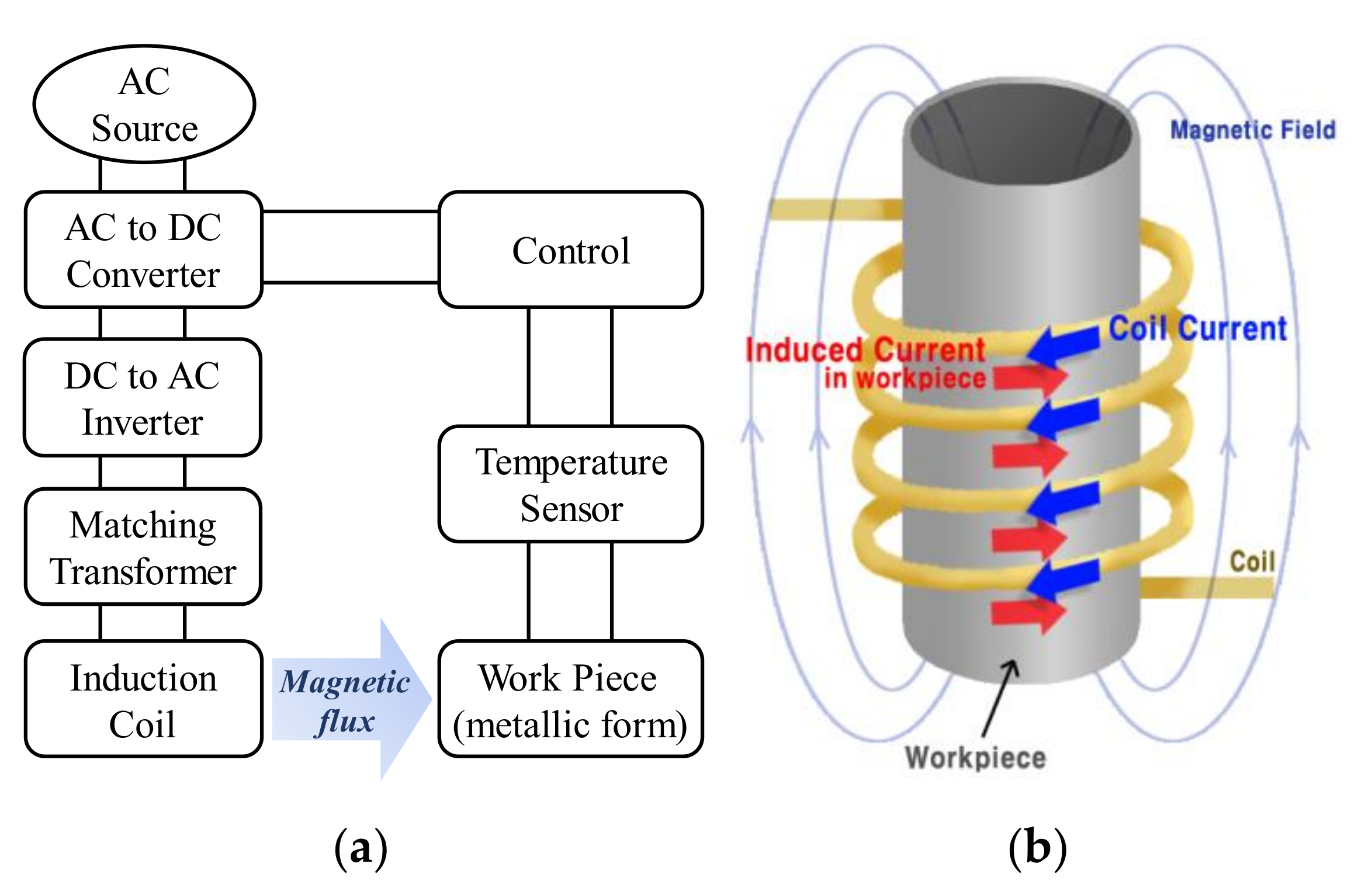
In this study, an induction heating system capable of efficiently converting electric energy to heat was developed. Figure 1a shows a block diagram of the induction heating system connected to temperature-control devices. The converter delivers power from the alternating current (AC) source to the inverter after converting AC into direct current (DC). The inverter generates the desired frequency from the rectified DC using insulated gate bipolar mode transistor switches used for high current. The matching transformer between the inverter and induction coil enables the inverter output to be transmitted to the coil with low loss. It also transforms the inverter output current into a high current which is advantageous for induction heating. The magnetic flux generated by the current in the coil develops an eddy current on the surface of the work piece (metallic form in this study), as shown in Figure 1b. The eddy current functions as a source of heat for concrete curing. To alter the formwork surface temperature, the current of the coil that adjusts the eddy current intensity is controlled by the temperature sensor and the control device connected between the formwork and converter.
2.2. Finite Element Method (FEM) Analysis for Concrete Curing
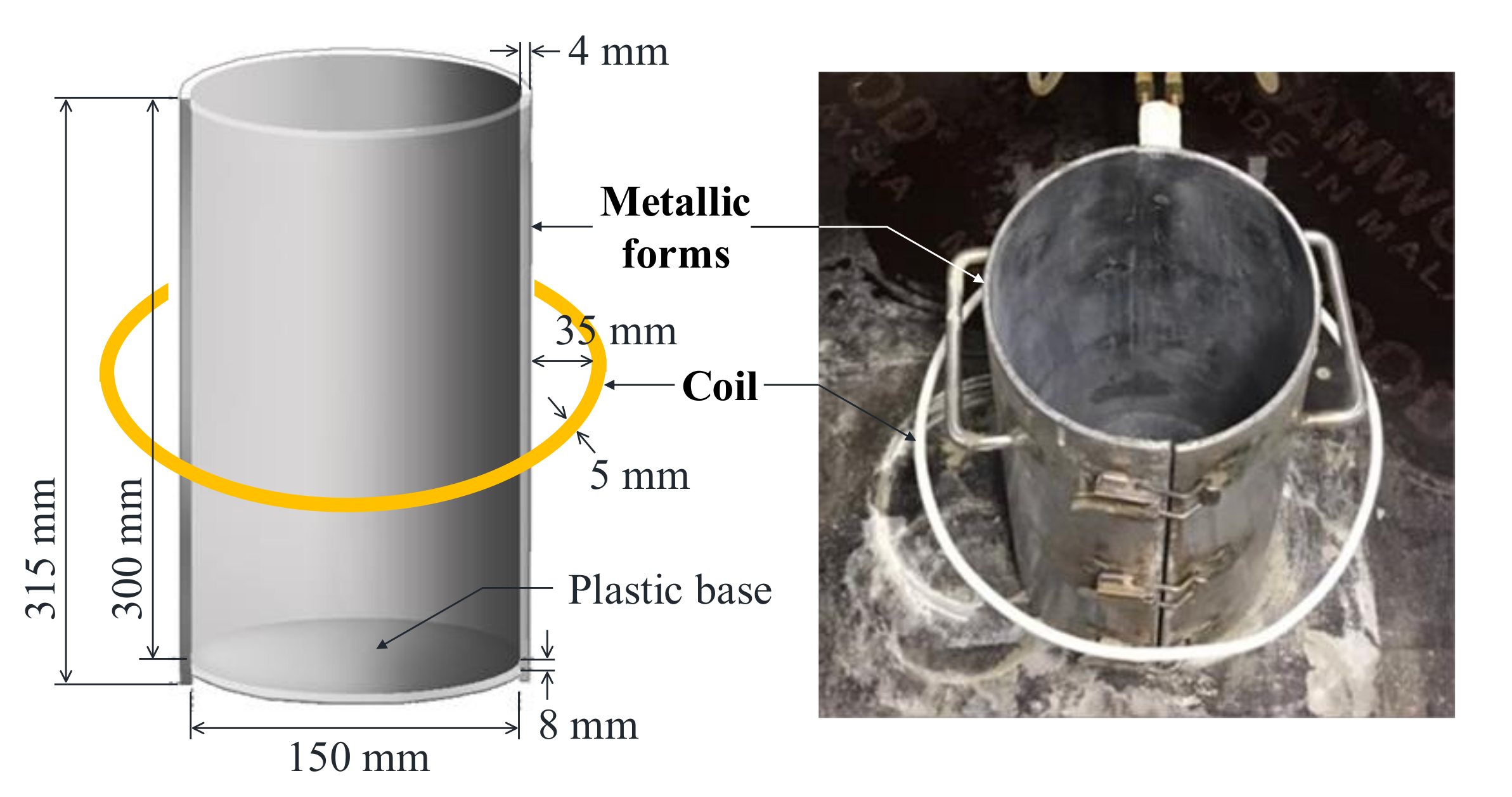
As a first step in the application of an induction heating system for concrete curing, FEM-based thermal analysis was carried out in this study to select the most appropriate materials for fabricating concrete formwork. In the analysis, metallic forms made using three different materials (steel, stainless steel, and aluminum) were heated by induced magnetic field and the maximum temperatures generated in the forms were evaluated. It is well known that the efficiency of an induction heating system is the highest when the system has closed coils because this type of coil is useful for producing a strong magnetic field. Therefore, concrete structures applicable to closed coils, such as columns and piers, were selected. Concrete cylindrical specimens with a diameter and height of 150 mm and 300 mm, respectively, were used to simulate actual columns or piers. Figure 2 illustrates the metallic forms and coil that were simulated in the FEM analysis. The induction coil was designed as a circular tube with outer and inner diameters of 5 mm and 4 mm, respectively, on a copper conductor. The distance between the coil and form was 35 mm, and one-turn coil was applied. A commercial FEM simulator, Altair FLUX, was used to analyze the formwork heating conditions. In the FEM simulation, the convergence criterion was set to 10−4 of accuracy threshold with 100 of maximum iterations for computing the relaxation factor for Newton-Raphson [15].
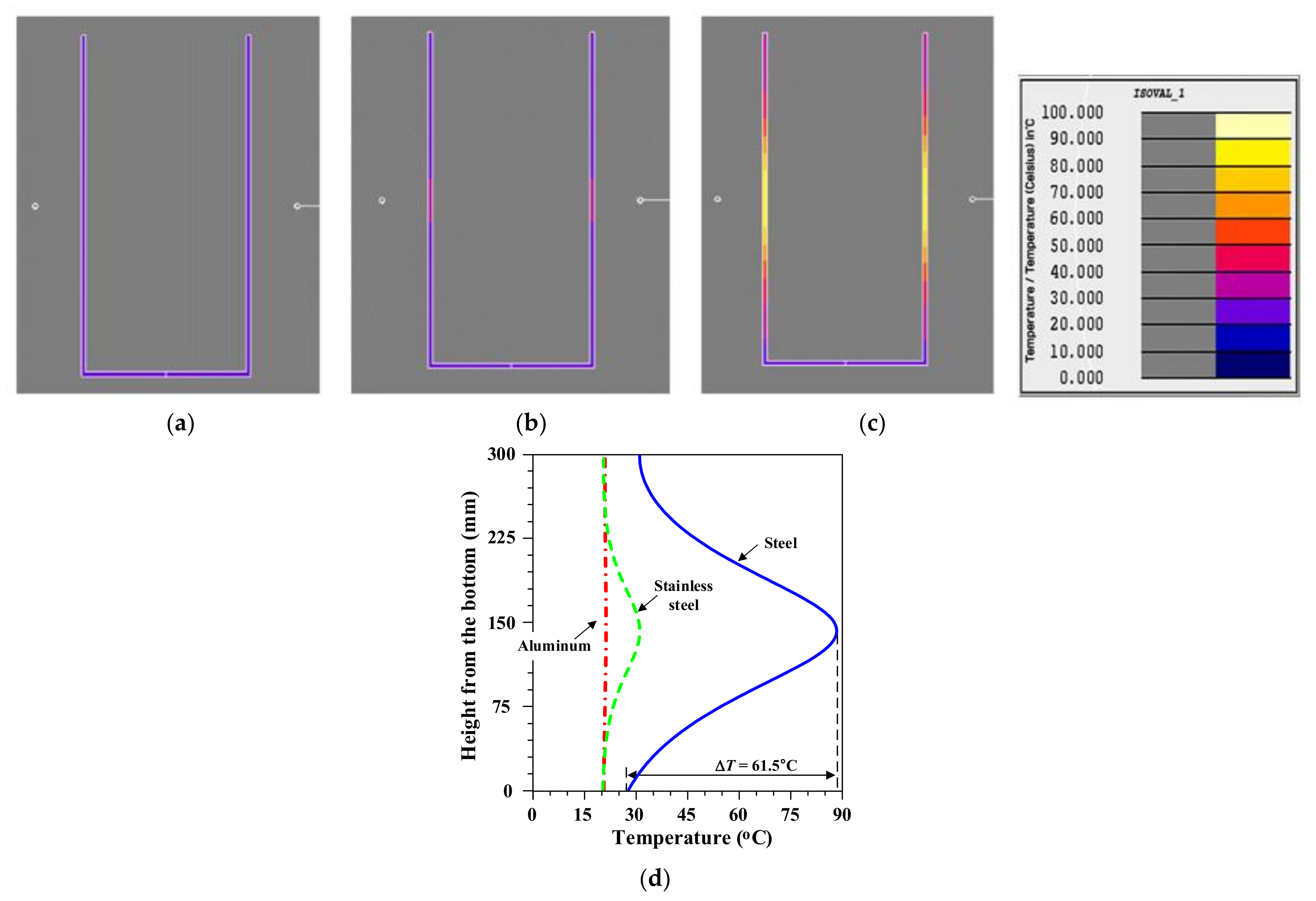
Figure 3 shows the temperature distribution of the inner surface of the forms made from the three different materials (aluminum, stainless steel, and steel), obtained by FEM analysis. The increase in temperature of the formwork was analyzed to select the most appropriate form material. The position of the coil was set at the midpoint of the height of the formwork so that the temperature distribution was symmetrical. It was observed that the maximum temperature of the steel form increased to 89 °C, whereas the temperature of the stainless steel and aluminum forms rarely increased. The general equation for power, P, produced by eddy currents in a conducting mass is:
where is the magnetizing force, is the permeability of the material, is the frequency, is the resistivity of the material, is the length of the conductor, and is the shape factor of the conductor which is a value affected by the structure’s shape [16].
From Equation (1), the higher the permeability of the conductor, the higher is the power produced by eddy current. Equation (1) verifies that induction heating by steel is more efficient because the relative permeability of steel, stainless steel, and aluminum is 4000, 500, and 1, respectively, in the simulation.
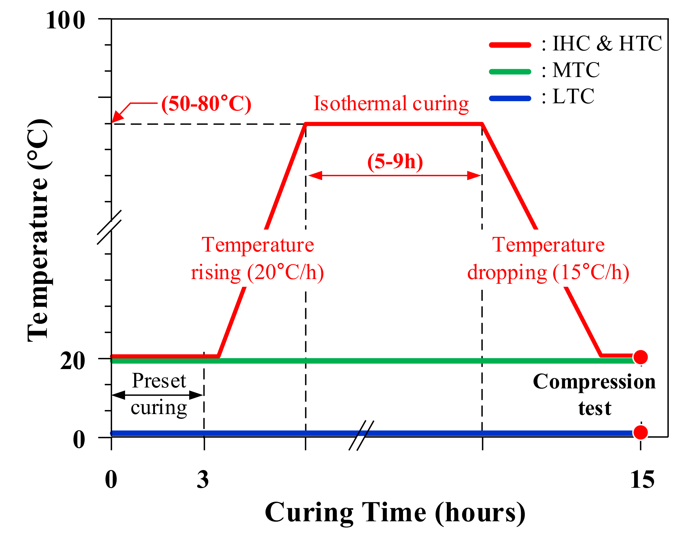
The uniform distribution of the heat generated in the metallic form should be distributed uniformly along the entire height to ensure homogenous curing of the concrete. For this purpose, a suitable arrangement of induction coils should be determined. An excessive number of coil turns causes not only low profit, but also a decrease in system efficiency due to mismatch with the inverter. Therefore, FEM analyses considering the arrangement of induction coils from one to three turns were carried out in this study. This analysis result was compared with the result of the heating performance test of formwork. A steel form that generated a significantly high temperature by induced magnetic field, as shown in Figure 3d, was used as the concrete form. This steel form was heated in accordance with the temperature regime, shown as a red line in Figure 4. It is noted that this temperature regime is similar to that of a typical steam curing method that is currently in use for the production of precast concrete products in Korea [17]. It is also noted that the sections of this curing regime where the temperature either increases or decreases were selected to prevent delayed ettringite formation, in accordance with the recommendations of Portland Cement Association (PCA) [18]. The applied heating regime consists of five steps: (1) maintain the ambient temperature of 20 °C, (2) increase the temperature at a rate of 20 °C/h, (3) maintain the maximum temperature of 70 °C for 5 h, (4) decrease the temperature at a rate of 15 °C/h, and (5) maintain the ambient temperature of 20 °C. The temperature distribution inside the surface of the steel form in the maximum temperature region (step 3) was analyzed through FEM simulation and experiment.
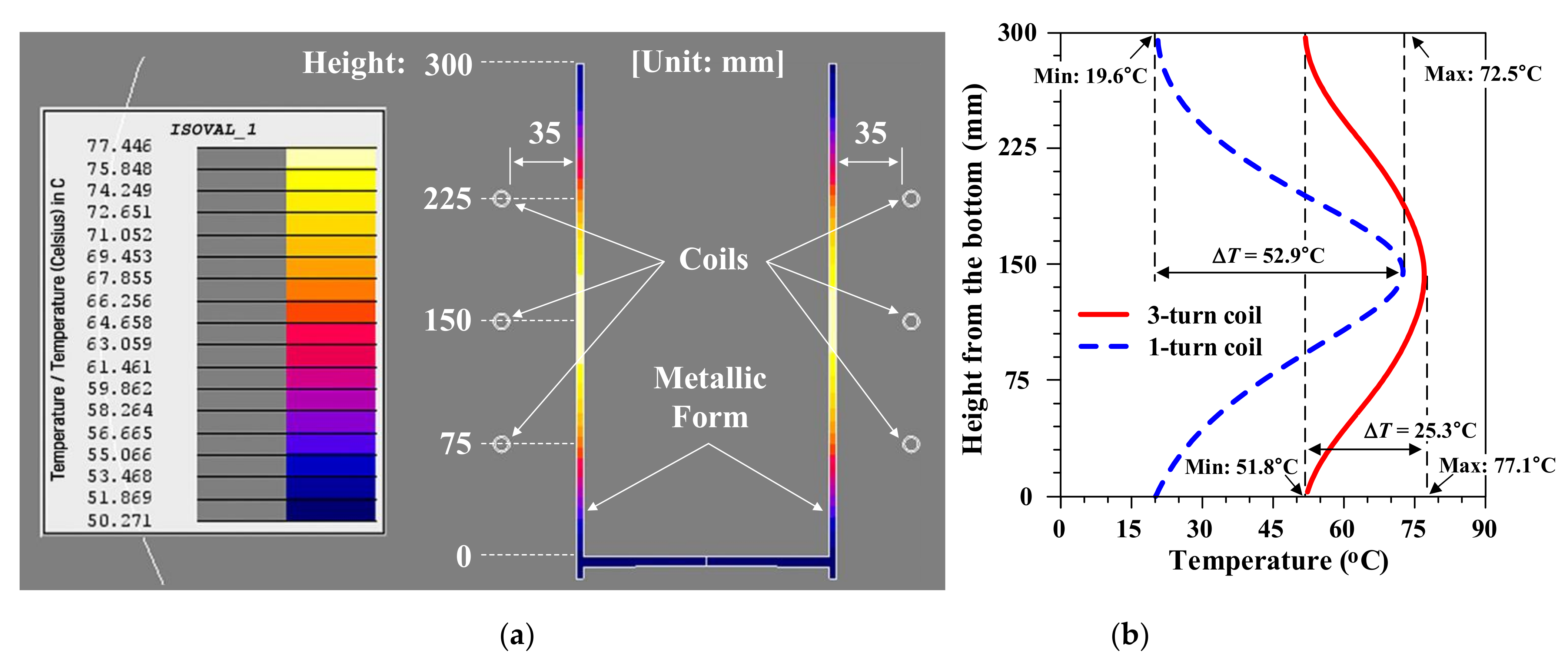
The temperature distribution on the surface of the formwork by a three-turn induction heating coil is shown in Figure 5a. The coil turns were equally spaced with 75 mm intervals, located at 75 mm, 150 mm, and 225 mm from the bottom of the steel form. A temperature of approximately 65–77 °C was distributed from 75 mm to 225 mm, the regions where the coils are located. Furthermore, temperatures at the top and bottom ends of the steel form found to be higher than approximately 50 °C. From the results of the FEM-based thermal analysis, the difference between the maximum and minimum temperatures was over 50 °C when a one-turn induction coil was used, whereas it was reduced to approximately 25 °C when a three-turn induction coil was used (see Figure 5b). In addition, it was confirmed that the temperature uniformity according to the height of the form surface increased further when a three-turn coil was used. This indicated that the use of the three-turn induction coil for concrete curing can yield sufficiently high temperatures above 50 °C as well as increased temperature uniformity along the entire height of the steel form.
2.3. Comparative Temperature Distributions in Metallic Formworks
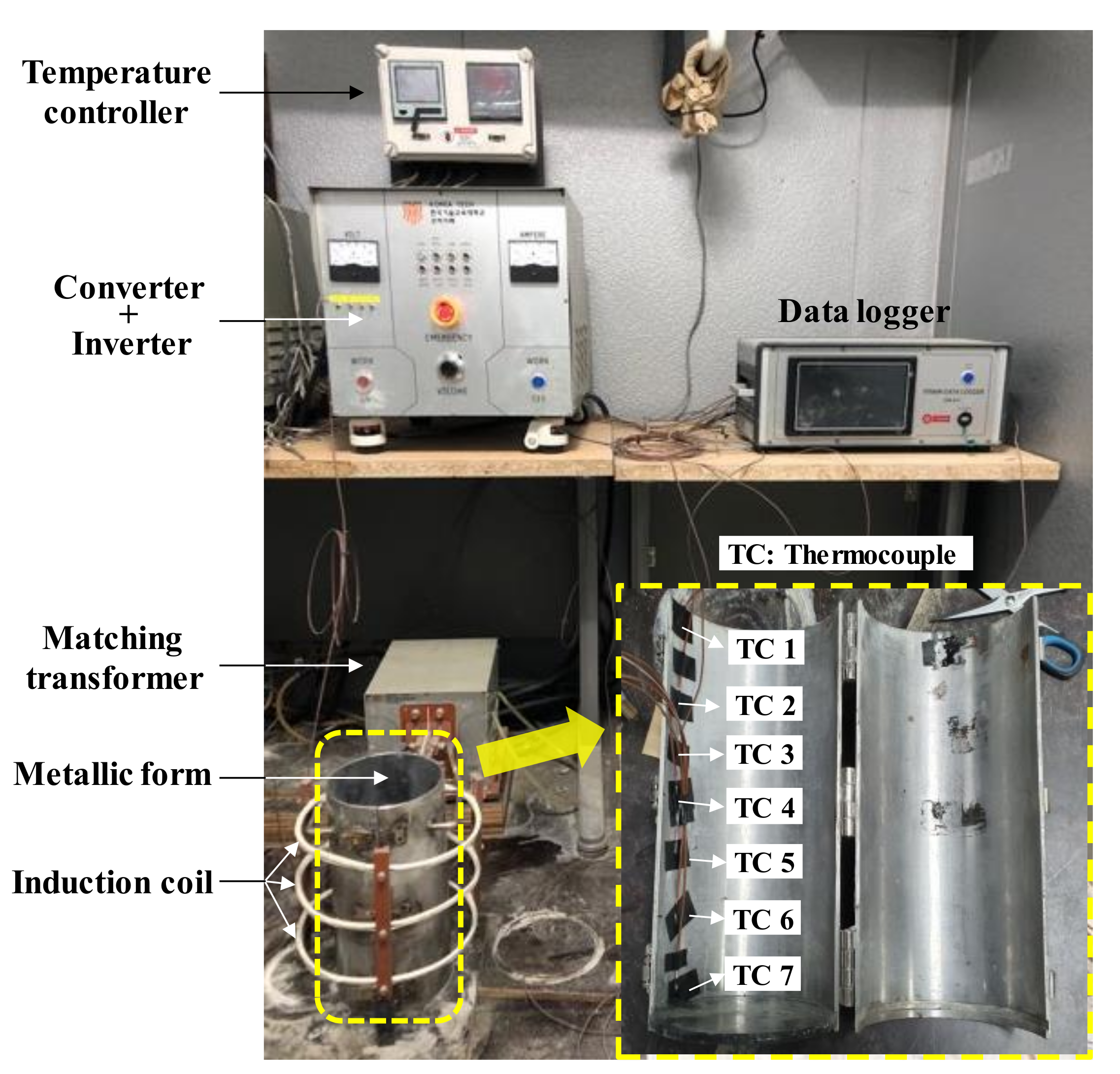
To compare with the FEM-based thermal analysis results, an experiment was performed on the temperature distribution of a formwork. The formwork heating experiment was carried out using a three-turn coil, which displayed a more uniform temperature distribution in the analysis (see Figure 5b). Figure 6 shows the induction heating system used in the experiment. The system generates an induction frequency of 40 kHz from a 60 Hz AC source through the converter and inverter. A current of 2.75 A and voltage of 94 V were measured at the output of the inverter. The output current is delivered to the coil after being increased by a 12:1 ratio by the matching transformer. The inverter output current is adjusted to control the temperature measured by the thermocouples attached inside the formwork. The magnetic flux created by the three-turn coil heats the surface of the formwork. It is important to obtain a uniform surface temperature to cure the concrete inside the formwork uniformly. The experiment was performed to assess the temperature distribution in a temperature equilibrium state after the formwork surface temperature had attained the maximum value. This is because temperature variation is important in the step where the maximum temperature is maintained (Step 3; see Figure 4). In the experiment, the temperature at each thermocouple was recorded after 30 min at the maximum temperature equilibrium.
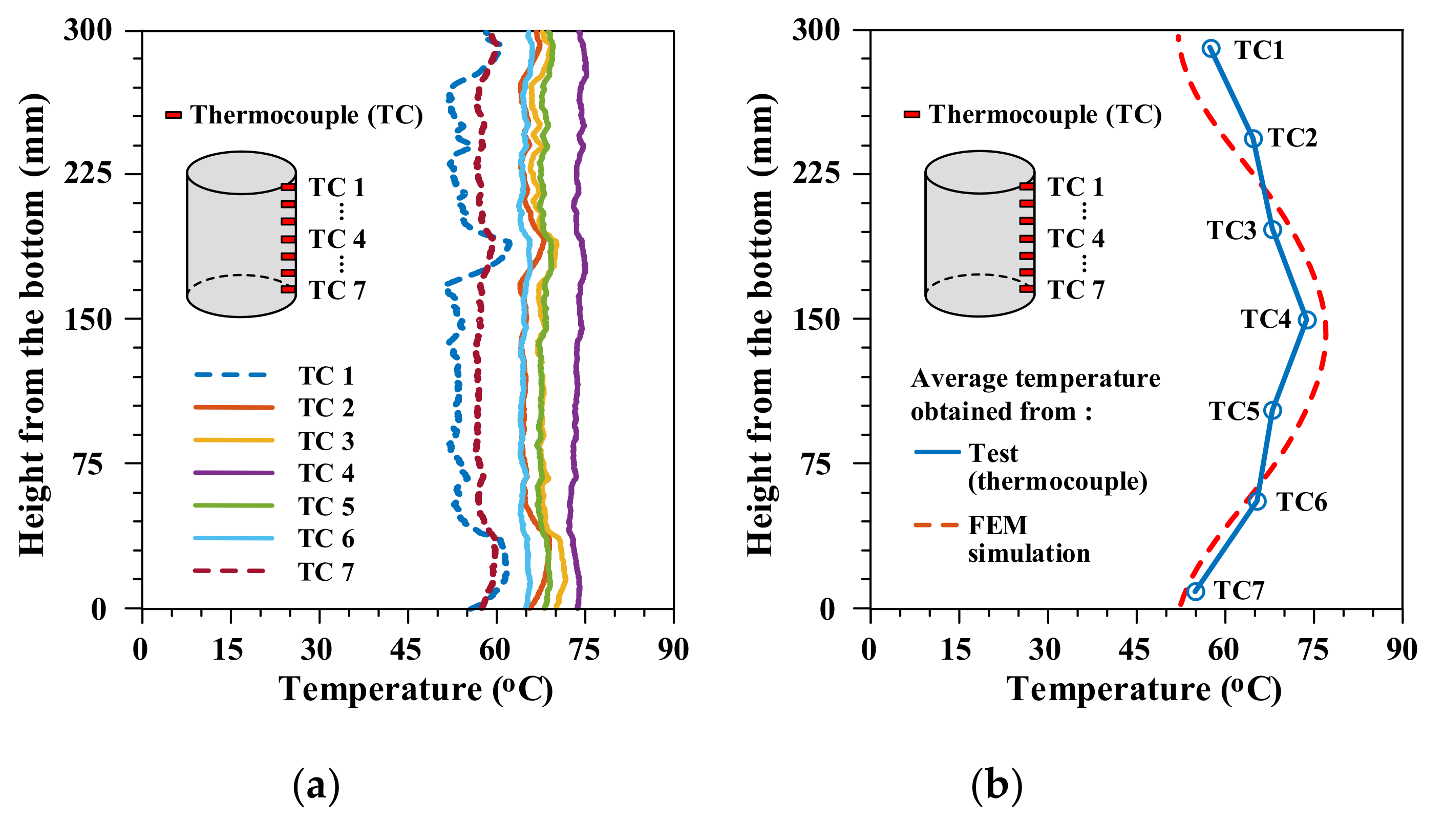
Figure 7a shows the temperature values obtained from each thermocouple attached to the inner surface of the formwork, over a period of 25 min. During the measurement time, the temperature values measured by the thermocouples mostly remain constant. Thermocouples 1 and 7, which were located at the top and bottom ends of the formwork, recorded relatively low temperatures of 51–62 °C and 55–60 °C (dot lines in Figure 7a), respectively. The other thermocouples maintained 65–75 °C (solid lines in Figure 7a). Figure 7b shows the average temperatures measured by each thermocouple, obtained by averaging the data captured during the 25 min in Figure 7a, together with the temperature variation obtained in the FEM simulation (Figure 5b), for comparison. The temperature values measured by thermocouples 2–6 in Figure 7b range from 65 °C to 75 °C. Meanwhile, those measured by thermocouples 1 and 7, which are located at the top and bottom ends of the cylinder, are close to 55 °C and 57 °C, respectively. That is, by comparing the temperature values obtained from the tests and FEM simulations, it was verified that the test results of the induction heating of formwork were highly similar to the results of the FEM-based temperature analysis.
3. Properties of Concrete after Curing
3.1. Test Program
3.1.1. Test Specimens and Variables
To investigate the efficiency of the use of the induction heating system for concrete curing, the temperature distribution during curing and the compressive strength of the heat-cured concrete were evaluated. The primary variables of the investigation were the heat curing conditions, such as the maximum curing temperature and duration, as well as the size of the concrete specimens or steel forms. Table 1 summarizes the test variables of the investigation. It is noted that some of the specimens in Table 1 have been previously tested by the authors [13] and were used as benchmarks for further investigation considering additional variables. The temperature variation curves applied during curing are shown in Figure 4. The maximum curing temperature varied from 50 °C to 80 °C and was maintained for 5 h to 9 h. Three different sizes of steel forms, having diameters of 300 mm, 150 mm, and 100 mm, were considered for the tests to investigate the efficiency of induction heating considering the size of the concrete members. These steel forms had identical thickness (4 mm) as in the FEM simulation and experiments in Section 2.
3.1.2. Materials
The concrete mix applicable to cold weather for bridge piers, having a water-cement ratio (w/c) of 38.3% and a sand-to-aggregate ratio (S/a) of 47.9%, was used in this study and detailed mix proportion of concrete is given in Table 2. A type I ordinary Portland cement (OPC) with a density of 3.15 g/cm3, a fineness of 3000 cm2/g, and an average particle size of 13.2 μm was used. Crushed coarse aggregate with a maximum aggregate size of 25 mm, density of 2.67 g/cm3, and fineness modulus of 6.12, as well as washed sand with a density of 2.56 g/cm3 and fineness modulus of 2.99 were used. A high-performance water-reducing agent (polycarboxylate super-plasticizer) was added to the mixture to achieve adequate workability and viscosity. The ratios of the quantity of superplasticizer to the total quantity of cement, ranging from 0.75% to 0.90%, are also listed in Table 2. The steel forms for casting concrete were fabricated similarly as illustrated in Figure 2, albeit with varying sizes as indicated in Table 1. The bottom plate of these steel forms was fabricated using a heatproof plastic as not to prevent induced magnetic field flow.
3.1.3. Curing
After concrete casting, the top surface (casting surface) of the all cylinder specimens was immediately covered and sealed with plastic sheets to prevent abrupt water evaporation and rapid setting during curing. Then, each of three cylinder specimens in the same variable was cured under four different curing conditions as listed below and the detailed curing regime is also shown in Figure 4.
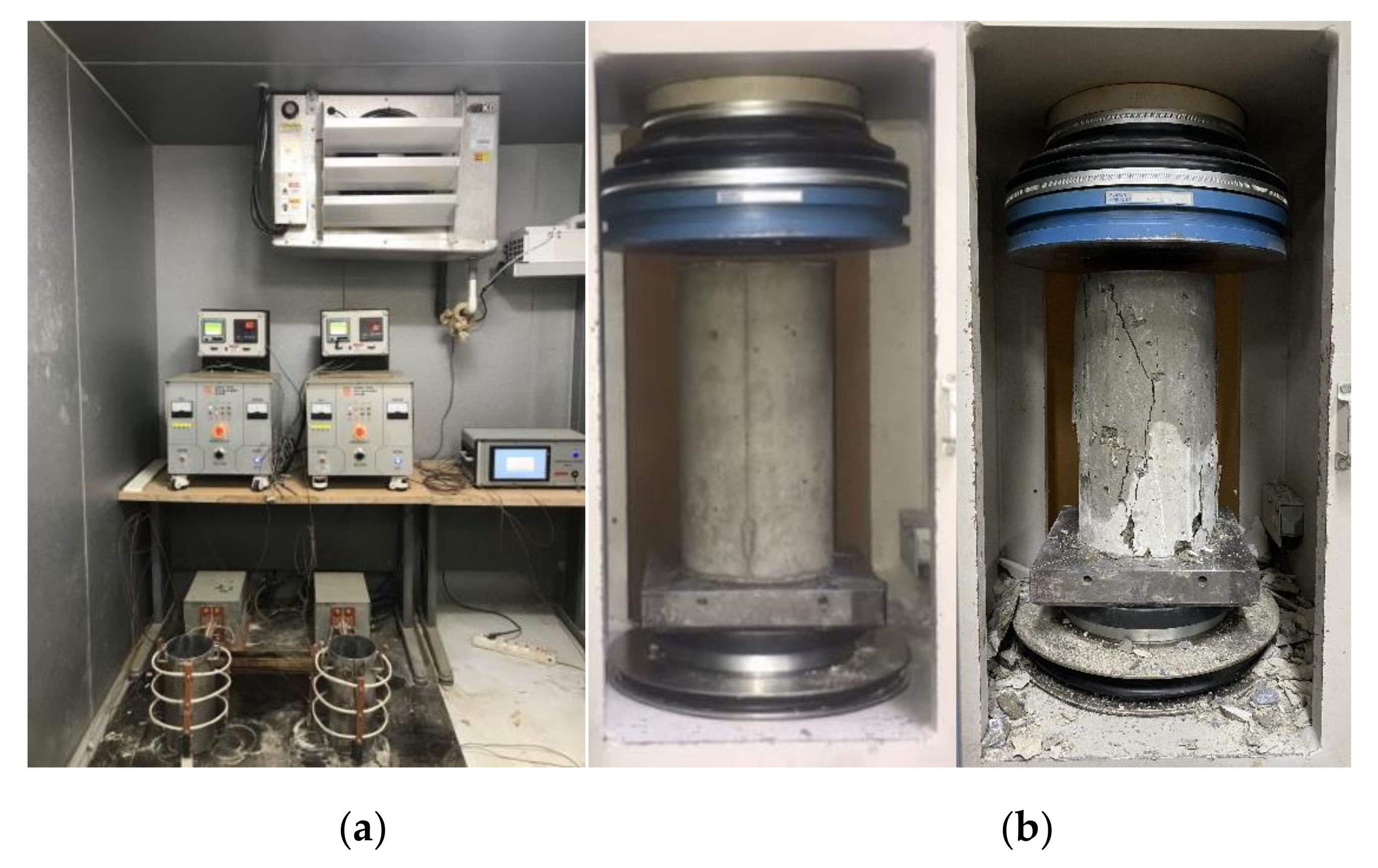
(1) Induction heat curing (IHC): this is considered primarily as a variable in this study. In order to simulate cold weather concrete conditions, concrete specimens were stored in a constant temperature chamber, targeted to maintain 0 °C, immediately after casting. Meanwhile, steel forms containing concrete were heated using an induction heating system according to the temperature hysteresis, specifically the red line in Figure 4. This curing regime comprised 3 h of ambient temperature after casting, followed by a temperature increase at the rate of 20 °C/h up to the maximum temperatures of 50–80 °C. This maximum temperature was maintained for 5 h–9 h and then, the temperature decreased to ambient temperature at the rate of 15 °C/h. After curing was performed at ambient temperature for 15 h, compression tests were carried out to determine the early age strength. Figure 8a shows the test chamber that simulated cold weather conditions (0 °C), test specimens, and setup for IHC.
An induction heating system with a maximum output electric power of 7 kWh and resonance frequency of 40 kHz was used for the IHC, as illustrated in Figure 1 and Figure 6. According to the FEM simulations and steel form heating test results described in Section 2, coils having three turns with a distance of 75 mm between coils were applied since this arrangement of coils provided the most uniform temperature distributions along the entire height of the steel form. The temperature hysteresis for IHC, shown in Figure 4, is simulated precisely by a temperature controller that operates based on the proportional integral derivative (PID) method. This system controls the output electric power supplied by the power converter, by considering the difference between the target temperature and the temperature measured using a thermocouple located at the mid-height and inner surface of the form in contact with the concrete. The temperature distributions in the concrete specimens were measured using several thermocouples installed in the concrete. Additional verification of the temperature distribution was performed by photographing the concrete surface and formwork surface with an infrared thermal imaging camera.
(2) Low-temperature curing (LTC): this simulates the cold weather conditions of a typical winter day in Korea. Immediately after casting, all the specimens were stored in the same chamber as that for IHC. However, additional heat curing was not applied. The curing regime for LTC is shown as a blue line in Figure 4. A very low temperature of approximately 0 °C was maintained for 15 h before the compression tests.
(3) Ambient temperature curing (ATC): this was carried out as a benchmark for comparison with the other curing conditions. The curing regime for ATC is shown as a green line in Figure 4. A comparison of the compressive strength results of concrete specimens subjected to different curing conditions with the results of concrete subjected to ATC could account for the difference in concrete compressive strength across the concrete mixes.
(4) High-temperature curing (HTC): this represents curing conditions with elevated temperatures. The cylindrical specimens were stored in a constant temperature chamber and the air in the chamber was heated according to the curing regime identical to that for IHC (the red line in Figure 4).
3.1.4. Test Method
To investigate the efficiency of induction heating with regard to the strength development of concrete, the compressive strengths of concretes cured at four different curing conditions were evaluated. The compressive strengths immediately after 15 h of curing were determined from three cylindrical specimens of dimensions ϕ150 × 300 mm for each curing condition in accordance with ASTM C 39 [19]. It is noted that the compressive strengths of the specimens SS4-5h-70, for which steel form of a smaller size was applied, was measured using three cylindrical specimens of dimensions ϕ100 × 200 mm. For the specimens LS4-5h-70 with a cross-section of ϕ300 mm, three cylindrical cores of dimensions ϕ100 × 200 mm were extracted from the specimens immediately after curing for compression tests. In order to compare compressive strengths of concrete with different dimensions, size effect should be considered [4]. However, current research, studied the size effect of concrete subjected to uniaxial compression, showed that the strengths of ϕ150 × 300 mm and ϕ100 × 200 mm cylinders with the same length-to-diameter ratio (L/D) are almost the same for lower strength concrete [20,21,22]. Therefore, the conversion factor that accounts for the different sizes of concrete specimens was not considered in this test program. The compression tests for all the cylinders were carried out using a universal testing machine (UTM) with a maximum capacity of 2000 kN and the setup for the tests is shown in Figure 8b. Three additional cylinders that were subjected to ATC were removed from the steel forms 15 h after concrete casting. Then, these were cured in a water storage tank (moisture curing) at a temperature range of 20 ± 2 °C until 28 days. Compression tests were carried out on these additional specimens to examine the specified design concrete strength at 28 days and use the results as benchmarks to compare the strength of concretes under the different curing regimes.
3.2. Results and Discussion
3.2.1. Temperature Distribution during Curing
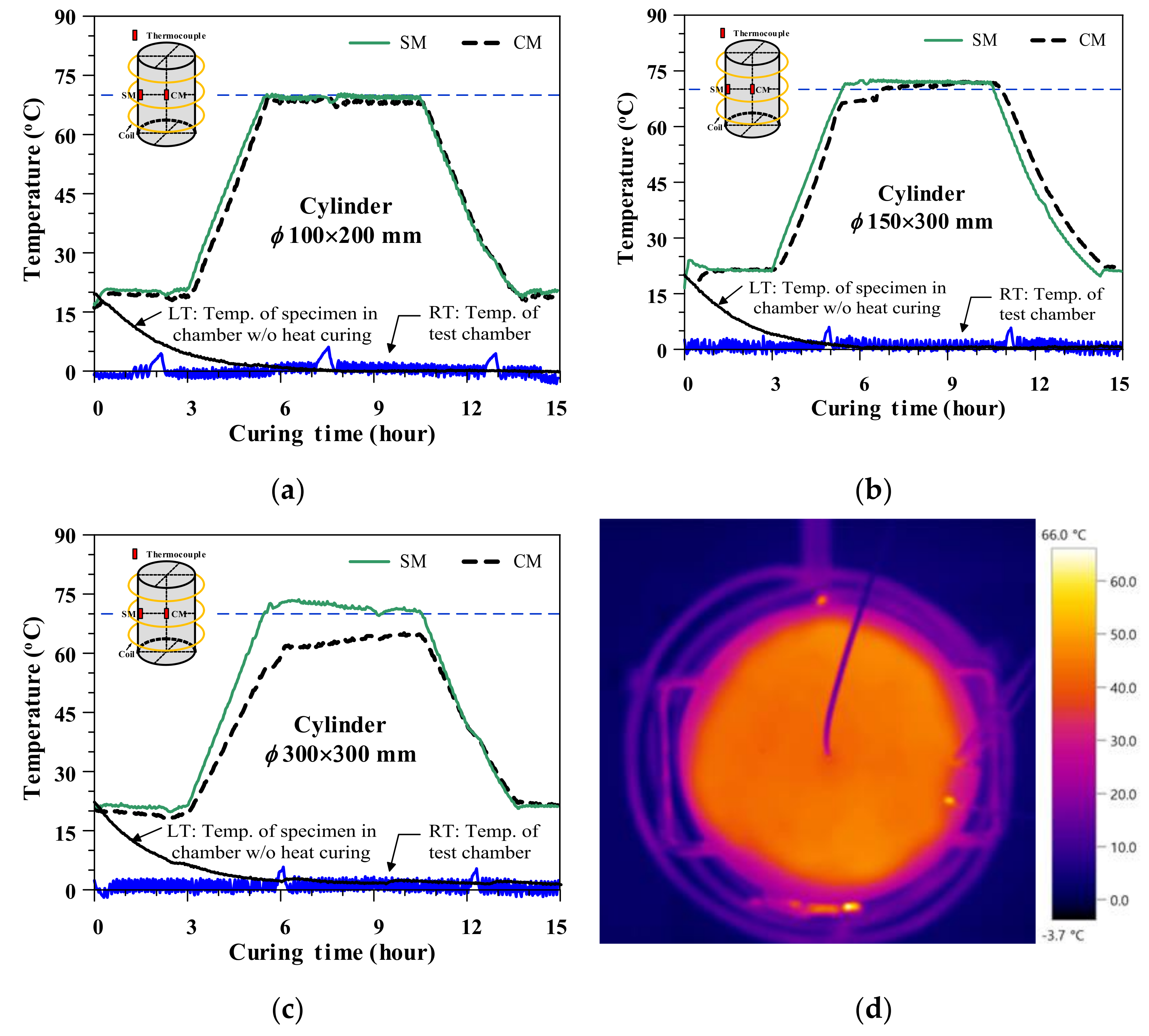
Typical temperature distributions of concrete that were measured during induction heat curing are illustrated in Figure 9. Specifically, Figure 9a–c show the temperature distributions of the cylinders with diameters of 100 mm (SS4-5h-70), 150 mm (S4-5h-70), and 300 mm (LS4-5h-70), respectively. In Figure 9, the thermocouple RT represents the room temperature of the test chamber and this data demonstrates that a low temperature of approximately 0 °C was maintained in the test chamber to simulate cold weather concrete conditions. It is noted that the slight increase in the temperature of the test chamber every 6 h (hump of RT in Figure 9) is owing to the defrosting cycle of the chamber to prevent freezing. The thermocouple LT in Figure 9 represents the temperature measured at the center of the cross-section of a cylinder in the test chamber without heat curing. At the beginning of the tests, the temperature was approximately 20–24 °C because the concrete was cast at ambient temperature. Then, the inner temperature of the concrete cylinder gradually decreased to a temperature similar to that of the test chamber at around 4 to 6 h, maintained until the end of testing. This result indicates that the inner temperature of concrete could be reduced to a very low value according to the surrounding temperature, particularly in winter, although hydration heat occurred in the concrete. Therefore, frost is likely to occur in concrete cast in the winter season if additional heat curing is not applied.
The cylindrical specimens of relatively small sizes, both ϕ100 × 200 mm and ϕ150 × 300 mm, exhibited quite similar temperatures at the inner surface of steel form and the center of concrete, as shown in Figure 9a,b. The temperature at the top surface of the concrete cylinder of dimensions ϕ150 × 300 mm, which was measured using infrared thermal imaging (see Figure 9d), was quite uniform as well through the entire cross-section. This result consistent with the measurements obtained using the thermocouples. It is noted that the temperature at the top surface of the concrete is marginally lower than that inside the concrete, because the top surface is adjacent to the low-temperature air (approximately 0 °C). However, in the case of the cylindrical specimen with a diameter of 300 mm, the temperature at the inner surface of the steel form tended to increase faster than the temperature at the center of the concrete and the temperature differences in the maximum temperature regions were approximately 10–17 °C. Furthermore, the target temperature could not be achieved in the interior of this specimen. These results indicate that the heat generated in the steel form was efficiently transferred to the interior of the concrete in the case of small specimens and, therefore, the entire cross-section of small-sized concrete structures can be heated uniformly by applying an induction heating system. Meanwhile, the heat generated in the steel forms could not be transferred fully to the interior of the concrete when the specimen size increased, resulting in temperature differences between the interior and surface of the concrete. Nevertheless, the measured temperature differences of 10–17 °C were not significant compared to the temperature difference required to cause cracking of concrete (exceed 20 °C) as suggested by FitzGibbon [23].
3.2.2. Compressive Strength Results
The compressive strength results of concretes subjected to different curing methods are given in Table 3. In this Table, the term f15h represents the compressive strength results of the concrete measured at 15 h, immediately after curing. The term fc′ represents the specified design concrete strength at 28 days, applicable only to ATC specimens, and this strength considered as a benchmark to compare the strength of concretes under different curing regimes. The strength, f15h, was normalized with respect to the same age strength of concrete cured at the ambient temperature, fATC, to account for the different concrete strengths in each variable, represented as f15h/fATC. The strength, f15h, is normalized with respect to fc′ as well, and is represented as f15h/fc′ in Table 3.
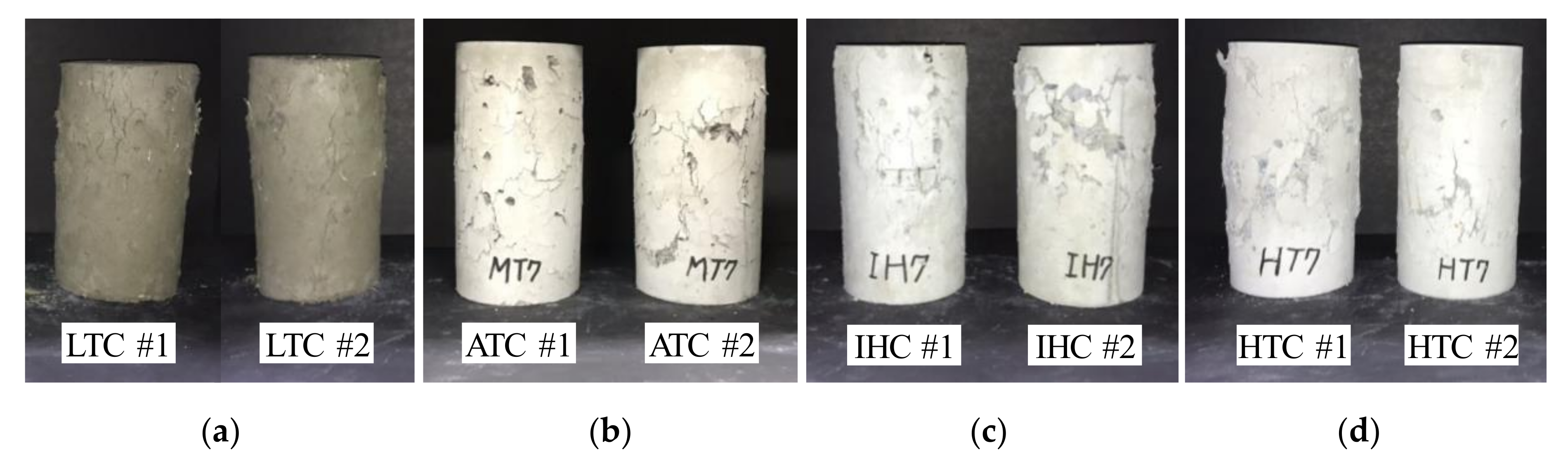
All the specimens cured in low-temperature chambers (LTC specimens) exhibited strength values of 0.2–0.4 MPa at 15 h, which are equivalent to approximately 2–3% of the strength of concrete cured at ambient temperature and of the same age. Neville [4] indicated that hydration of cement occurs even at a very low temperature of approximately −10 °C. However, if concrete that has not been set is permitted to freeze, its setting and hardening are delayed because of the unavailability of water for chemical reactions. In this study, LTC and IHC specimens were stored in the 0 °C chamber immediately after concrete casting and, therefore, it appears that the hydration reaction did not occur. This result also verified the results obtained by examining the temperature of concrete in the chamber discussed in Figure 9, namely that the inner temperature of the concrete cylinder gradually decreased to the temperature of the test chamber. Furthermore, a comparison (shown in Figure 10) of the surface textures of concretes cured under four different conditions, at the time of testing (15 h), also demonstrates suspended and delayed setting and hydration of concrete at around the water freezing temperature. ACI Committee 306 [2] recommends the provision of appropriate protection immediately after the placement of concrete in cold weather to prevent early age freezing. They recommended that the temperature of concrete that is newly placed in cold weather should be kept close to 13 °C for cross-sectional sizes of concrete less than 300 mm.
Most of the IHC specimens cured in a low-temperature chamber and applied with steel form heating using an induction system exhibited compressive strength values exceeding 20 MPa even at a very early age of 15 h, except for the marginally lower strength values of 18.9 and 19.8 MPa for the specimens S4-8h-50 and S4-5h-60, respectively. Furthermore, the strength values are 1.65–2.33 times higher than those of the ambient-cured specimens at the same age, and attained 34–54% of the specified 28-day strength values. Furthermore, the compressive strength results of IHC specimens are comparable to the results of HTC specimens cured in a high-temperature chamber, although the IHC specimens were cured in a chamber with a significantly lower temperature than that for HTC specimens. These results demonstrate the efficiency of the use of an induction heating system for curing concrete to develop early age strength in cold weather conditions.
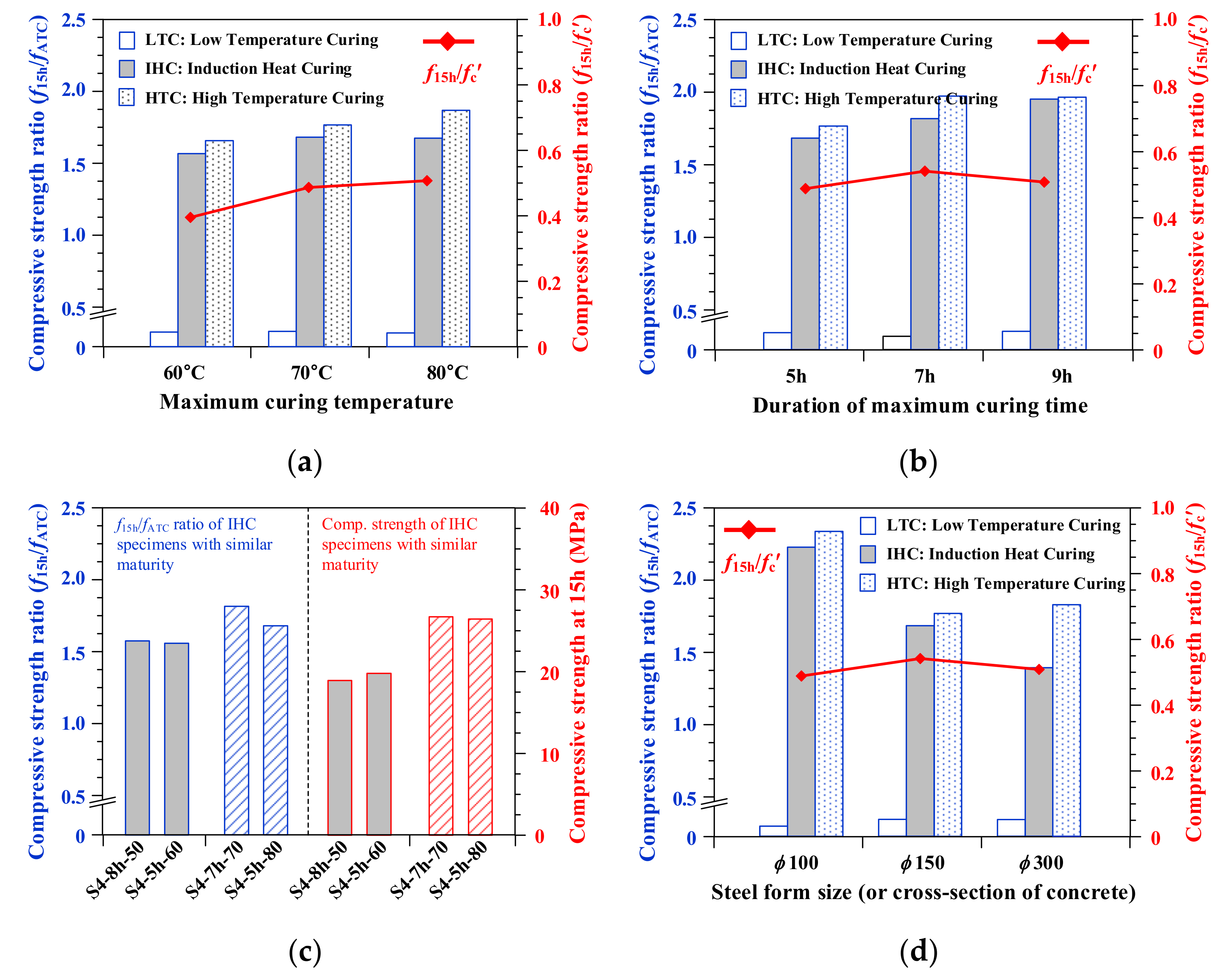
The normalized compressive strengths, f15h/fATC and f15h/fc′ listed in Table 3, of concretes cured under different curing conditions are compared in Figure 11 to investigate the effects of each variable on the strength development at a very early age. Figure 11a compares the normalized compressive strengths at 15 h that applied varying maximum curing temperatures. For the HTC specimens, the compressive strength ratio continuously increased with increasing maximum curing temperature. The compressive strength ratio of the IHC specimens also increased by 7% with increasing the maximum curing temperatures from 60 °C to 70 °C, but further increase in the compressive strength ratio was not observed for curing temperatures above 70 °C. Furthermore, the compressive strength ratio of the IHC specimen at 15 h to its specified compressive strength, f15h/fc′, also increased up to the maximum curing temperature of 70 °C and further increase was not significant for above this. The limited test results of this study indicate that the maximum curing temperature of approximately 70 °C is reasonable for the early-age strength development of induction heat-cured concrete.
Figure 11b compares the normalized compressive strengths at 15 h obtained by applying varying durations of maximum curing time. It is noted that the maximum curing temperatures for all the specimens in Figure 11b were 70 °C. Both IHC and HTC specimens, which were supplied with additional heat for curing, exhibited higher compressive strength ratios at an early age with increasing the curing period. This result is consistent with the maturity theory, which explains that the strength gain by concrete is a function of time and temperature [2,4]. The maturity of concrete is generally defined as Σ(time interval × temperature). The effects of maturity on concrete strength cured by the induction heating system can be clearly shown by Figure 11c. Each pair of specimens together in Figure 11c have similar maturity (i.e., S4-8h-50 and S4-5h-60 has similar maturity, while S4-7h-70 and S4-5h-80 has similar maturity). The graphs in red on the right-hand side represent the compressive strength values of induction heat-cured concretes at 15 h, while the graphs in blue on the left-hand side represent compressive strength ratios of the same specimens compared with the strength values of the ATC specimens, f15h/fATC. The results of Figure 11c demonstrate that the early age strength of induction heat-cured concrete is proportion to the value of the maturity factor.
The effects of the cross-sectional dimensions of the specimens on the early age strength development of heat-cured concrete can be examined using the results of Figure 11d. Both IHC and HTC specimens having the smallest cross-sectional dimension, ϕ100, exhibited early age strength values that were significantly higher than those of larger specimens. This result can be attributed to the effective transfer of heat from the steel form to the entire cross-section of concrete (see Figure 9a), providing sufficient curing. The compressive strength ratio of IHC specimens continually decreased as the size of the specimens increased and this result can be possibly explained by the results of temperature distributions in Figure 9. As previously indicated, the non-uniformity of the temperature distributions inside concrete increased as the specimen size increased because the heat generated in the steel form for curing concrete is not sufficiently transferred to the center of concrete if the specimen size is large. Thereby, induction heat-cured concrete of larger specimens exhibited lower strength development at an early age. Meanwhile, HTC specimens with a cross-section of ϕ300 mm exhibited slightly higher strength than that of specimens with a cross-section of ϕ150 mm. This is inconsistent with the results of IHC specimens and may be attributed to the difference in heat transfer mechanisms between HTC and IHC. As mentioned above, IHC initially heats the steel form located outside the concrete, and then the generated heat is transferred to the interior of the concrete. In the case of HTC, concrete curing was carried out in the test chamber at elevated temperature and therefore, the entire cross-section of the cylindrical specimens in this chamber was heated uniformly. This resulted in quite similar early-age strength development for the various cross-sectional dimensions. In summary, the effectiveness of IHC decreases as the specimen size increases because the heat generated in the steel form could not be sufficiently transferred to the center of the concrete. This resulted in lower strength development at an early age for induction heat-cured concrete with lager cross-sectional dimensions that should be properly addressed for the practical utilization of the IHC method in construction fields.
4. Conclusions
In this study, a novel accelerated concrete curing method using an induction heating system was developed and its efficiency was demonstrated by FEM simulation and experimental investigations. The following conclusions are drawn within the scope of this study:
- (1)
- The effects of induction heat curing on the increase in the temperature of the metallic forms with different materials were evaluated using FEM-based thermal analysis. The results revealed the superior heating performance of steel form by induced magnetic field compared with those for aluminum and stainless steel forms. Therefore, it is concluded that the steel form is most appropriate for concrete curing using an induction heating system.
- (2)
- The results from both FEM-based thermal analysis and formwork heating experiment verified that the temperature uniformity across the height of the formwork surface was higher when an equally spaced three-turn coil, rather than a one-turn coil, was used.
- (3)
- Concrete cured in the low-temperature chamber by using an induction heating system achieved sufficiently high compressive strength even at a very early age. This demonstrates the effectiveness of using an induction heating system for concrete curing in cold weather.
- (4)
- Early strength development of induction heat-cured concrete is proportion to the value of the maturity factor. This indicates that both the maximum temperature and duration of induction heat curing affect the early age strength of concrete.
- (5)
- The temperature distributions in the concrete cured using the induction heating system were not uniform and the early-age strength decreased when the cross-sectional dimension of the specimen increased to approximately 300 mm because the heat generated in the steel form could not be sufficiently transferred to the center of the concrete.
- (6)
- The proposed method using induction heating is possibly applicable for curing both precast concrete and in-situ concrete (particularly in cold weather) in practice. Performing a preliminary thermal analysis, considering the size and shape of the concrete members, is required for determining the appropriate arrangement of the induction coils. Nevertheless, further investigations that account for practical member size, environmental conditions, and construction process are required for the utilization of the induction heat-curing method in construction fields.
Author Contributions
Conceptualization, C.-H.A. and H.-O.S.; Funding acquisition, H.-O.S.; Investigation, C.-H.A., J.L., D.-J.K. and H.-O.S.; Supervision, C.-H.A. and H.-O.S.; Writing—original draft, C.-H.A. and H.-O.S.; Writing—review & editing, H.-O.S. All authors have read and agreed to the published version of the manuscript.
Funding
This research was supported by a grant (20CTAP-C152012-02) from Technology Advancement Research Program (TARP) funded by Ministry of Land, Infrastructure and Transport of Korean government and also supported by research fund of Chungnam National University.
Acknowledgments
This research was supported by a grant (20CTAP-C152012-02) from Technology Advancement Research Program (TARP) funded by Ministry of Land, Infrastructure and Transport of Korean government and also supported by research fund of Chungnam National University.
Conflicts of Interest
The authors declare no conflict of interest.
References
- Mehta, P.K.; Monteiro, P.J. Concrete: Microstructure, Properties and Materials, 3th ed.; McGraw-Hill: New York, NY, USA, 2006. [Google Scholar]
- ACI Committee 306 (306R-88). In Report on Cold Weather Concreting; American Concrete Institute: Farmington Hills, MI, USA, 1988.
- Makul, N.; Rattanadecho, P.; Agrawal, D.K. Applications of microwave energy in cement and concrete—A review. Renew. Sustain. Energy Rev. 2014, 37, 715–733. [Google Scholar] [CrossRef]
- Neville, A.M. Properties of Concrete, 4th ed.; J. Wiley: New York, NY, USA, 1996. [Google Scholar]
- Lee, M.-G. Preliminary study for strength and freeze-thaw durability of microwave-and steam-cured concrete. J. Mater. Civil Eng. 2007, 19, 972–976. [Google Scholar] [CrossRef]
- Leung, C.K.Y.; Pheeraphan, T. Determination of optimal process for microwave curing of concrete. Cem. Concr. Res. 1997, 27, 463–472. [Google Scholar] [CrossRef]
- Makul, N. Production of high-early-compressive-strength Portland cement paste using low-pressure microwave-accelerated heating and curing: processing characteristics and factors affected. Heliyon 2019, 5, e02098. [Google Scholar] [CrossRef] [PubMed] [Green Version]
- Makul, N.; Agrawal, D.K. Influence of microwave-accelerated curing procedures on the microstructure and strength characteristics of Type I-Portland cement pastes. J. Ceram. Process. Res. 2011, 12, 376–381. [Google Scholar]
- Sohn, D.; Johnson, D.L. Microwave curing effects on the 28-day strength of cementitious materials. Cem. Concr. Res. 1999, 29, 241–247. [Google Scholar] [CrossRef]
- Somaratna, J.; Ravikumar, D.; Neithalath, N. Response of alkali activated fly ash mortars to microwave curing. Cem. Concr. Res. 2010, 40, 1688–1696. [Google Scholar] [CrossRef]
- Choi, H.; Koh, T.; Choi, H.; Hama, Y. Performance evaluation of precast concrete using microwave heating form. Materials 2019, 12, 1113. [Google Scholar] [CrossRef] [PubMed] [Green Version]
- Koh, T.; Hwang, S.; Pyo, S.; Moon, D.; Yoo, H.; Lee, D. Application of low-carbon ecofriendly microwave heat curing technology to concrete structures using general and multicomponent blended binder. J. Mater. Civil Eng. 2019, 31, 04018385. [Google Scholar] [CrossRef]
- Lee, J.; Kim, K.; Ahn, C.-H.; Back, J.; Shin, H.-O. Compressive strength of heat-cured concrete based on induction heating. J. Korean Soc. Hazard Mitig. 2019, 19, 331–337. [Google Scholar] [CrossRef]
- Kim, D.-J.; Choi, Y.-S.; Jeong, H.-J.; Shin, H.-O.; Ahn, C.-H. Analysis of temperature distribution of mold for curing concrete based on induction heating. J. Korean Inst. Illum. Electric. Install. Eng. 2020, 34, 16–23. [Google Scholar]
- Altair HyperWorks Flux 2019.1 User’s Guide. Available online: https://www.altair.com/flux/ (accessed on 7 December 2020).
- Stansel, N.R. Induction Heating; McGraw-Hill: New York, NY, USA, 1949. [Google Scholar]
- KCI PM 303.1:15. In Concrete Curing; Korea Concrete Institute: Seoul, Korea, 2015.
- PCA R&D Serial No. 2166. In Ettringite Formation and the Performance of Concrete; Portland Cement Association (PCA): Skokie, IL, USA, 2001.
- ASTM C 39M-15a. In Standard Test Method for Compressive Strength of Cylindrical Concrete Specimens; ASTM International: West Conshohocken, PA, USA, 2015.
- Lee, B.J.; Kee, S.-H.; Oh, T.; Kim, Y.-Y. Effect of cylinder size on the modulus of elasticity and compressive strength of concrete from static and dynamic Tests. Adv. Mater. Sci. Eng. 2015, 2015, 580638. [Google Scholar] [CrossRef] [Green Version]
- Talaat, A.; Emad, A.; Tarek, A.; Masbouba, M.; Essam, A.; Kohail, M. Factors affecting the results of concrete compression testing: A review. Ain Shams Eng. 2020, in press. [Google Scholar] [CrossRef]
- Vandegrift, D.; Schindler, A. The Effect of Test Cylinder Size on the Compressive Strength of Sulfur Capped Concrete Specimens; Highway Research Center and Department of Civil Engineering at Auburn University: Auburn, AL, USA, 2006; p. 83. [Google Scholar]
- FitzGibbon, M.E. Large Pours for Reinforced Concrete Structures—2: Heat. Available online: https://trid.trb.org/view/45991 (accessed on 7 December 2020).
Figure 1.
Induction heating system: (a) block diagram; (b) induction heating principle.

Figure 2.
Details of metallic forms with a coil for finite element method (FEM) simulation.

Figure 3.
Temperature distribution for different formwork materials: temperature contour of forms made with (a) aluminum, (b) stainless steel, and (c) steel; (d) temperature distribution comparison.
Figure 3.
Temperature distribution for different formwork materials: temperature contour of forms made with (a) aluminum, (b) stainless steel, and (c) steel; (d) temperature distribution comparison.

Figure 4.
Heating scenario.

Figure 5.
Temperature distribution by a three-turn coil: (a) temperature distribution on the surface of formwork; (b) temperature distribution according to height.
Figure 5.
Temperature distribution by a three-turn coil: (a) temperature distribution on the surface of formwork; (b) temperature distribution according to height.

Figure 6.
Experiment set-up: induction heating system and inside the metallic form with thermocouples.
Figure 6.
Experiment set-up: induction heating system and inside the metallic form with thermocouples.

Figure 7.
Temperature data: (a) of sensors attached to the inner surface of the formwork; (b) measured average temperature distribution.
Figure 7.
Temperature data: (a) of sensors attached to the inner surface of the formwork; (b) measured average temperature distribution.

Figure 8.
Test setup for induction heat curing and compression test: (a) test chamber, specimens, and setup for IHC; (b) setup for compression test.
Figure 8.
Test setup for induction heat curing and compression test: (a) test chamber, specimens, and setup for IHC; (b) setup for compression test.

Figure 9.
Temperature distributions of the concrete measured during induction heat curing: (a) cylinder with dimensions ϕ100 × 200 mm; (b) cylinder with dimensions ϕ150 × 300 mm; (c) cylinder with dimensions ϕ300 × 300 mm; (d) infrared thermal camera image of the cylinder with ϕ150 mm.
Figure 9.
Temperature distributions of the concrete measured during induction heat curing: (a) cylinder with dimensions ϕ100 × 200 mm; (b) cylinder with dimensions ϕ150 × 300 mm; (c) cylinder with dimensions ϕ300 × 300 mm; (d) infrared thermal camera image of the cylinder with ϕ150 mm.

Figure 10.
Appearance of cylinders after compression tests at 15 h: (a) LTC specimens; (b) ATC specimens; (c) IHC specimens; (d) HTC specimens.
Figure 10.
Appearance of cylinders after compression tests at 15 h: (a) LTC specimens; (b) ATC specimens; (c) IHC specimens; (d) HTC specimens.

Figure 11.
Comparisons of compressive strength ratios: (a) effects of maximum curing temperature; (b) effects of duration of maximum curing time; (c) effects of maturity for IHC specimens; (d) effects of cross-sectional size.
Figure 11.
Comparisons of compressive strength ratios: (a) effects of maximum curing temperature; (b) effects of duration of maximum curing time; (c) effects of maturity for IHC specimens; (d) effects of cross-sectional size.


Table 1.
Test variables for evaluating the properties of concrete cured by induction heating.
| Specimen | Max. Curing Temperature | Metallic Form | Note | |||
|---|---|---|---|---|---|---|
| Tmax (°C) | Duration (Hour) | Material | Thickness (mm) | Dimensions (mm × mm) | ||
| S4-8h-50 | 50 | 8 | Steel | 4 | ϕ150 × 300 | Effects of curing temperature and duration |
| S4-5h-60 | 60 | 5 | ϕ150 × 300 | |||
| S4-5h-70 | 70 | 5 | ϕ150 × 300 | |||
| S4-5h-80 | 80 | 5 | ϕ150 × 300 | |||
| S4-7h-70 | 70 | 7 | ϕ150 × 300 | |||
| S4-9h-70 | 70 | 9 | ϕ150 × 300 | Effect of specimen size | ||
| SS4-5h-70 | 70 | 5 | ϕ100 × 200 | |||
| LS4-5h-70 | 70 | 5 | ϕ300 × 300 | |||
Table 2.
Mix proportion of concrete.
| Mixture | w/c (%) | S/a (%) | Unit Weight (kg/m3) | SP 1 | |||
|---|---|---|---|---|---|---|---|
| Water | Cement | Sand | Gravel | ||||
| OPC35 | 38.3 | 47.9 | 176 | 460 | 800 | 894 | 0.75–0.90 |
1 SP: Super-plasticizer (wt% to the cement).
Table 3.
Compressive strength results.
| Specimen | ATC | LTC | HTC | IHC | |||||||
|---|---|---|---|---|---|---|---|---|---|---|---|
| 1 [MPa] | 2 [MPa] | [MPa] | 3 | 4 | [MPa] | [MPa] | |||||
| S4-8h-50 | 12.0 | 59.4 | 0.2 | 0.02 | 0.00 | 19.8 | 1.65 | 0.33 | 18.9 | 1.58 | 0.34 |
| S4-5h-60 | 12.7 | 50.0 | 0.3 | 0.02 | 0.01 | 21.0 | 1.66 | 0.42 | 19.8 | 1.57 | 0.40 |
| S4-5h-70 | 15.4 | 53.1 | 0.4 | 0.02 | 0.01 | 27.2 | 1.77 | 0.51 | 25.9 | 1.68 | 0.49 |
| S4-5h-80 | 15.7 | 51.9 | 0.3 | 0.02 | 0.01 | 29.4 | 1.87 | 0.57 | 26.4 | 1.67 | 0.51 |
| S4-7h-70 | 14.7 | 49.4 | 0.3 | 0.02 | 0.01 | 29.0 | 1.97 | 0.59 | 26.7 | 1.82 | 0.54 |
| S4-9h-70 | 14.3 | 55.0 | 0.4 | 0.03 | 0.01 | 28.1 | 1.96 | 0.51 | 28.0 | 1.95 | 0.51 |
| SS4-5h-70 | 12.9 | 56.0 | 0.2 | 0.02 | 0.00 | 30.1 | 2.33 | 0.54 | 28.7 | 2.22 | 0.51 |
| LS4-5h-70 | 15.6 | 54.0 | 0.4 | 0.03 | 0.01 | 28.5 | 1.83 | 0.53 | 21.7 | 1.39 | 0.40 |
1f15h: compressive strength at an early age (15 h) considering different curing conditions. 2fc′: specified compressive strength at 28 days obtained by testing concrete cured at ambient temperature. 3f15h/fATC: compressive strength ratio of concrete at 15 h normalized to the strength of concrete cured at ambient temperature and of the same age. 4f15h/fc′: compressive strength ratio of concrete at 15 h normalized to the strength of concrete cured at ambient temperature and of the same age.
Publisher’s Note: MDPI stays neutral with regard to jurisdictional claims in published maps and institutional affiliations. |
© 2020 by the authors. Licensee MDPI, Basel, Switzerland. This article is an open access article distributed under the terms and conditions of the Creative Commons Attribution (CC BY) license (http://creativecommons.org/licenses/by/4.0/).
Share and Cite
MDPI and ACS Style
Ahn, C.-H.; Lee, J.; Kim, D.-J.; Shin, H.-O. Development of a Novel Concrete Curing Method Using Induction Heating System. Appl. Sci. 2021, 11, 236. https://0-doi-org.brum.beds.ac.uk/10.3390/app11010236
AMA Style
Ahn C-H, Lee J, Kim D-J, Shin H-O. Development of a Novel Concrete Curing Method Using Induction Heating System. Applied Sciences. 2021; 11(1):236. https://0-doi-org.brum.beds.ac.uk/10.3390/app11010236
Chicago/Turabian StyleAhn, Chi-Hyung, Jinbok Lee, Dong-Jin Kim, and Hyun-Oh Shin. 2021. "Development of a Novel Concrete Curing Method Using Induction Heating System" Applied Sciences 11, no. 1: 236. https://0-doi-org.brum.beds.ac.uk/10.3390/app11010236
Note that from the first issue of 2016, this journal uses article numbers instead of page numbers. See further details here.