1. Introduction
Recently, due to the rising crisis of traditional energy sources, new international directives regarding the promotion of energy from renewable sources have been published, as it is stated in [
1,
2]. As a result, research and application of sustainable energy, particularly photovoltaic (PV) power generation, have attracted more and more attention through various projects (e.g., EU and US Green Deal projects). As it is described in [
2,
3], the global concern for environmental issues and the need to mitigate the effects that result in global warming are the key drivers for enhanced power systems based on renewable energy sources. For this, as it is stated in [
2], renewable energy industries, markets, and policy frameworks are being developed rapidly and national power corporations encourage the installation of PV systems in an effort to accomplish both financial and environmental benefits. Adapted to cope with these environmental hurdles, during the last ten years PV capacity has grown worldwide, placing PVs at the forefront of technology development as it is stated in [
4].
PV systems are inherently exposed to atmospheric overvoltages (because of their installation position), which can damage critical parts of the equipment, resulting in power supply interruptions, extended failures of vital components of the systems, and serious hazards for human life. As it is mentioned in [
4], direct lightning strikes on photovoltaic panels or on the external lightning protection system (LPS) may lead to insulation breakdown, grounding potential rise, and panel and/or inverter destruction (melting). The aforementioned problems become more intense in the case of stand-alone photovoltaic systems, where there may not be an alternative power supply of the electrical installation. In [
5], the necessity of a risk management analysis according to the International Standards, and the importance of an extensive study of lightning protection systems are highlighted in order to apply appropriate protection measures against external surges. Considering that inadequate protection against lightning phenomena can delay the investment return of the PV system, it is highly recommended to take into account techno-economically balanced protection measures. Indeed, the design and implementation of an efficient LPS are of great importance for the secure operation of PV installations, of which the capital investments are significant. In fact, as it is highlighted in [
5], the cost of installing an LPS may be proven insignificant when compared to the revenue losses incurred due to damages in case of a lightning strike. The amplitude and the steepness of the lightning current, the characteristics of the LPS, the soil resistivity of the installation area and the geometrical and electrical characteristics of the grounding system are critical factors that influence the lightning protection of the PVs. In [
5], some of the aforementioned design parameters of an LPS on large-scale PV plants are studied, but without an in-depth review of the impact of multi-layer soil structures on the developed potential in case of a lightning strike.
Research, as described in a recent review on the performance of lightning protection on photovoltaic systems (roof mounted or solar farms) has just started due to high penetration on the power distribution grids [
6]. In [
4], the impact of a standard impulse lightning strike on the performance of single PV modules is evaluated. The impact of distributed generation on the lightning protection of distribution lines is examined in [
7,
8,
9]. Case studies are described in [
10] regarding the performance of an LPS on a Greek hybrid power network and in [
11,
12] regarding the effects of a lightning strike on different parts (AC or DC) of a PV park in Malaysia. Moreover, in [
13], a solar grid-connected PV module without LPS is modeled and simulations are performed under various scenarios, in order to assess its lightning performance and to highlight the importance of an LPS. In [
14], a new computer algorithm is presented that can be used to evaluate the risk of damage in PV systems and the need for installation of a lightning rod. Analysis of touch potentials in solar farms and recommendations to reduce them are presented in [
15] and the effect of group grounding on the potential rise across a solar farm during a lightning strike is simulated with the PSPICE software tool in [
16]. Finally, in [
17], PV generation connected to high-voltage generation and its impact on the proper operation of the protection systems of the power grid is studied. In [
18], the design of the grounding system on a hybrid power station (wind, PV, energy storage) is studied considering the soil structure.
In this paper, the developed potential caused by lightning surges in a 100 kWp PV system are estimated by using an appropriate simulation software. This is a particularly advantageous approach as it enables the evaluation of three lightning protection systems’ setups, i.e., an attached, a non-attached, and a modified non-attached lightning protection system, considering different soil structures and characteristics of the grounding system. In addition, the impact of the perimeter grounding and the grounding electrode length on the developed potential are investigated in this work. Finally, in the case of a non-attached and a modified non-attached system, simulation results are presented for a variable distance between the lightning rod and the metallic structure of the installation, as well as for different types of insulators.
It is worth mentioning that a thorough literature survey reveals that there is still little research that has been done on the impact of various parameters of an LPS (geometrical and/or structural) and of soil structure (single- or multi-layer with different resistivities and heights), on the developed potential, on a large-scale grid-connected PV park, in case of a lightning strike [
6]. In particular, based on previous years related scientific work, as it is described in [
5,
19], there is a necessity for further research on the optimal design of an LPS on large-scale solar applications.
Moreover, in the literature, various software tools are used for simulating the lightning performance of a grid-connected PV system. In [
5], simulation models are developed for an external LPS on a 150 kW PV park in order to assess the lightning current distribution across the PV park. In [
11,
12] the PSCAD software tool is used to model the LPS and the lightning strokes on PV systems and in [
20] multiple simulations are performed utilizing CDEGS in order to examine the safety voltage of critical facilities for large-scale PV parks in case of a ground fault. In this paper, the customization features of the widely known CDEGS software tool are taken advantage of, in order to investigate the performance of an LPS under the influence of various combinations of the aforementioned parameters. The outcomes of the current work are expected to contribute to the optimal techno-economical design of a reliable and effective lightning protection system on a grid-connected PV park, in an effort to improve its lightning performance and restrain the hazardous, for the equipment and personnel, developed potential in case of a lightning strike.
2. Protection of PV Systems against Lightning Overvoltages
As it is described in [
4,
19], PV modules are more vulnerable to direct lightning strikes than conventional low-voltage power distribution systems, due to installation on roofs, facades of buildings, and, in general, on unsheltered areas. For this, a risk assessment must be taken into account [
10] and if it is deemed necessary, a thorough study of the LPS of PV park must be conducted [
7]. Lightning and surge protective measures are described in IEC 62305 Standard (Parts 1 to 3) for conventional low-voltage distribution systems. Part 1 [
21] lists damages due to lightning, protection needs and measures and basic criteria for protection of structures. Part 2 [
22] provides the risk management procedure in order to evaluate the need of an LPS. Part 3 [
23] concerns the lightning protection system (LPS).
A necessary requirement for the efficient design of an LPS is to perform the previous stated risk assessment using the procedures and data stated in [
22]. The most susceptible parts of the PV installation should be taken into consideration and the consequences of a direct or indirect lighting flash should be studied. In general, lightning strikes result in breakdown of the insulation, serious damage of the electrical equipment, and rise of the grounding potential [
15]; the severity of the consequences are strongly influenced by the geometry of the PV system, the LPS, the peak current [
8], and the duration of the lightning flash and the lightning strike position [
24].
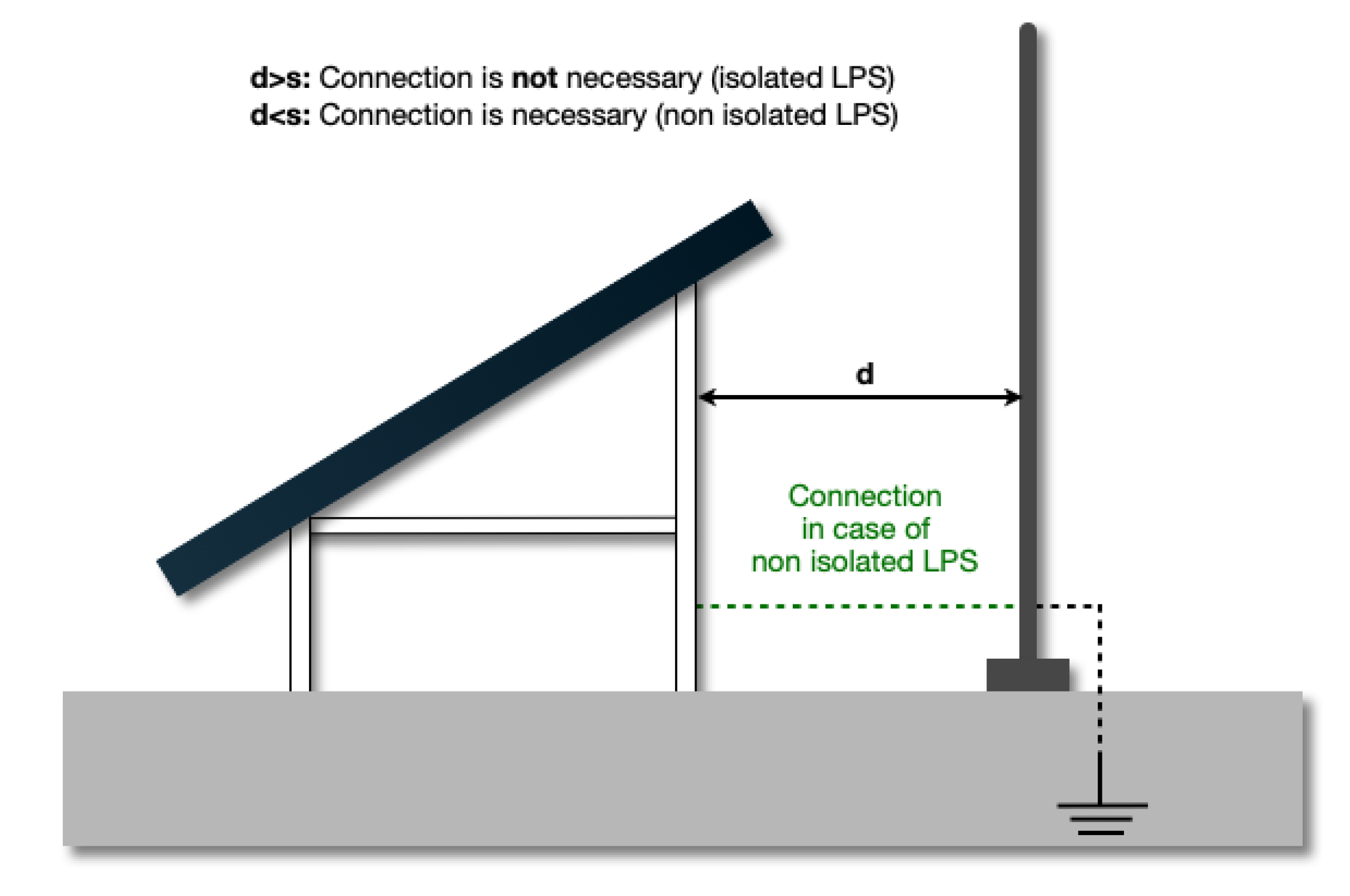
LPSs are divided into external and internal. Basic components of an external LPS are the air termination system, the down conductors, and the ground system. The air termination system captures the lightning discharge current and dissipates it harmlessly to earth via the down conductor and the ground termination system. Thermal and explosive effects caused at the occasion of a lightning strike and the consequences to the installation must be a guide in choosing the type of air termination system (isolated or non-isolated) [
23] (
Figure 1).
The earth termination system has a vital significance for the dispersion of the lightning current safely and effectively into the ground. According to [
14], grounding resistance lower than 10 Ω is recommended. To avoid galvanic corrosion, earth electrode material and connection clamps should be chosen carefully, taking into account PV frame and support structure materials. Open-field PV installation electrode arrangements are used for lightning protection. Moreover, the fundamental role of the internal LPS is to ensure avoidance of dangerous sparking due to the lightning current flowing through the external LPS or other conductive parts of the installation. The electrical interconnection can be achieved by equipotential bonding and surge protective devices, in the case that the direct connection with bonding conductors is not suitable.
4. Simulation Results
The simulations were performed using CDEGS (Current Distribution, Electromagnetic Fields, Grounding and Soil Structure Analysis) software suite [
28]. In detail, the system under examination was modeled implementing the HIFREQ computation module. The FFTSES computation module decomposed the selected time domain lightning signal in some computation frequencies, by means of the Fourier Transform, for the electromagnetic fields response (HIFREQ) and then reconstituted the time-domain response from the HIFREQ results (Inverse Fourier Transform). The scalar potential and electromagnetic field in the time domain are given by:
where
stands for the frequency spectrum of the lightning surge current and
are the unmodulated scalar potential, electric field, and magnetic field in the frequency domain, respectively [
28].
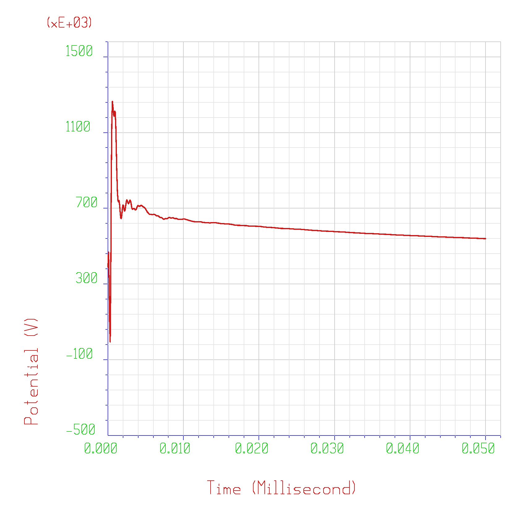
Figure 2 shows the 3D CDEGS model for both isolated and non-isolated LPSs. An example of the potential developed waveforms obtained from IFFT (Inverse Fast Fourier Transform) in the time domain for one observation point on the ground surface is shown in
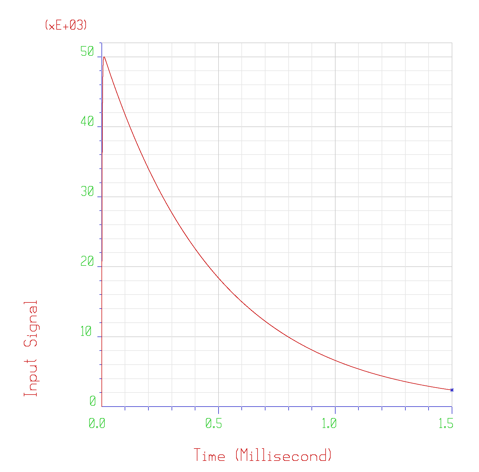
Figure 3. The comparison results of the maximum potential developed for the standard 10/350 μs lightning current waveform according to IEC 62305 (
Figure 4), for different cases, are presented in
Figure 5,
Figure 6,
Figure 7 and
Figure 8.
The computational method employed by HIFREQ module to solve Maxwell’s electromagnetic fields equations includes an improved version of the electric field point-matching approach and the moment method. Both the aboveground and buried conductors of the actual size computer model that was used were subdivided in small segments so that the thin wire approximation of the antenna theory could be met. After the current distribution calculation in the conductor network, the scalar potentials and the electromagnetic fields could be computed [
28].
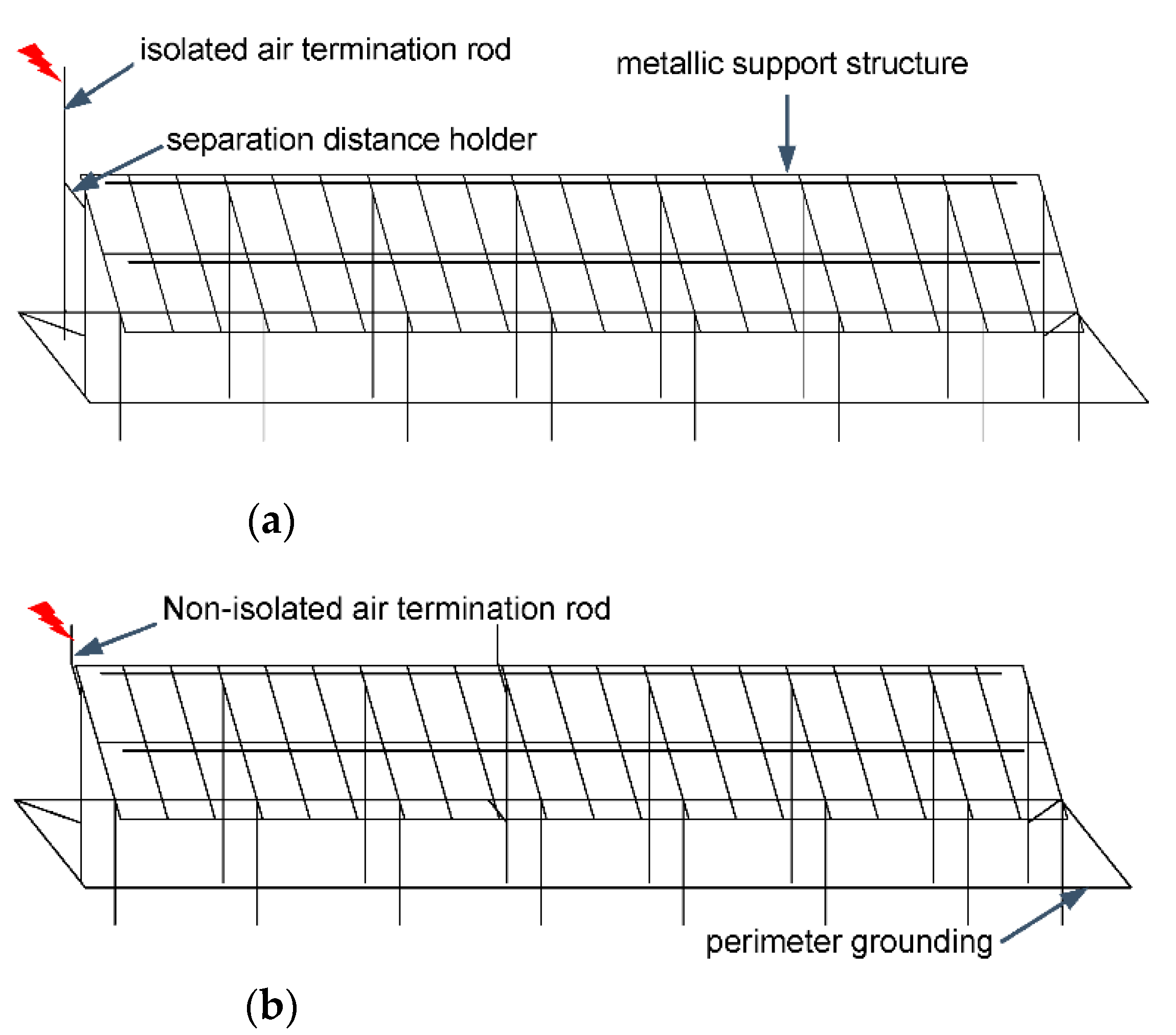
A 50 kA, 10/350 μs lightning strike (
Figure 4) on the air termination conductor (as shown in
Figure 2a,b) was simulated considering the two-layer soil structures indicated in
Table 1. In the case of the two-layer soil structure, ρ
1 is the resistivity of the first layer (starting from the soil surface), ρ
2 is the resistivity of the second soil layer and h
1 is the thickness of the upper soil layer. The second layer thickness is assumed to be infinite. The calculated grounding resistance (steady state) for the alternative soil structures is shown in the last column of
Table 1. The separation distance between the non-attached air termination rod (
Figure 2a) and PV panels is set at 0.1, 0.5, 0.75, and 1 m.
Figure 5 and
Figure 6 depict the calculated maximum values of the soil surface potential as a function of the distance between the air termination rod and the PV panels (system of
Figure 2a) for the aforementioned soil structures. The potential was calculated on the ground surface 1.5 m away from PV installation (
Figure 5) and at a 1 m distance from the air terminal struck by the lightning (
Figure 6). Touch voltages (
Figure 7) were computed considering a 70 kg human body standing on the ground surface at a 1 m distance from the air termination rod, touching the exposed metallic parts connected to the grounding system. As illustrated in
Figure 5 and
Figure 6 the separation distance affects soil structures C and D (greater upper layer resistivity) more than A and B.
Touch voltages for soil structure D (see
Table 1),
Figure 2a system, and three examined perimeter grounding cases (perimeter grounding buried at a depth of 0.5 m, on soil surface, and no perimeter grounding) are indicated in
Figure 7. The obtained results highlight that a perimeter grounding, depending on its depth below the ground, can significantly contribute to decreasing the developed touch voltages.
Attached and non-attached lightning protection systems are compared in
Figure 8 through the developed potential for soil structure D considering three systems i.e., attached system, non-attached system with insulating isolator, and non-attached system with conductive isolator. It should be noted that for the case of the attached system the distance between the air termination rod and the metallic support structure is fixed; therefore, the potential values are independent of the separation distance.
The developed potential for soil structure D was calculated for different depths of rod A (grounding electrode connected with the air termination rod), rods B (mounting poles of structural base), and rods C (grounding electrodes at the four edges of the perimeter grounding) resulting in six alternative grounding systems as presented in
Table 2 and
Figure 9. The maximum developed potential for soil structure D for each grounding system is presented in
Figure 10.
The influence of the increasing depth of the grounding electrode A connected to the air termination rod on the developed potential diminished for a rod height greater than 4 m (results of gs3 and gs4 were almost identical). Furthermore, the level of calculated potential was lower in the case of four grounding electrodes at the edges of perimeter grounding (gs6) than in the case of lengthening the mounting poles of the support construction (gs5), which is rather impractical as PV support constructions are manufactured in certain dimensions.
5. Discussion
To achieve an accurate picture of the lightning performance of the system under study, several issues need to be addressed, concerning different parameters (separation distance, depth of rods, soil structure, and grounding grid) that determine the developed potentials. According to the above simulations, the following outcomes are concluded:
The increase of the separation distance, s, has greater impact on the developed potential in the case of soil structures with greater upper layer resistivity compared to those with a lower one. (
Figure 5 and
Figure 6).
The installation of a perimeter grounding grid can significantly decrease the developed touch voltages (
Figure 7). An installed perimeter grounding grid increases the grounding area and leads to a lower grounding resistance value and, consequently to diminished developed touch voltages.
The lowest values of the developed potential are achieved in the case of non-attached LPS system with conductive isolator (
Figure 8). This result contributes to the design of grounding systems, as the reduction of hazardous overvoltages is a significant criterion for the selection of a lightning protection system.
The installation of rods on the perimeter grounding can contribute to decreasing the developed potential (
Figure 9) considering the soil structure. In case the soil resistivity of the upper layer is higher, compared to the bottom layers, the installed rods’ length should be such that part of them is buried beyond the upper layer boundaries. On the contrary, in case of a lower soil resistivity value of the upper layer, a horizontal grounding area increase would restrict the developed overvoltages rather than buried electrodes.
The results of the present work, the mounting position of the PV park, the geometrical—structural characteristics of the LPS, and the soil resistivity must always be taken into account in order to construct an efficient lightning protection system in a techno-economical way. Future work can include the examination of various soil structures (multi-layer horizontal or vertical with different values of resistivity), separation distances, and depths of rods and perimeter grounding grids in order to achieve the optimal design of the LPS and to minimize, as far as possible, the developed potentials, touch and step voltages.
6. Conclusions
In this paper, the developed potentials and touch voltages due to a lightning strike on a 100 kWp PV system were estimated, examining alternative scenarios. To mitigate the consequences and to avert dangers to human life because of an inefficient LPS system, critical parameters of the system configurations need to undergo detailed examination. The knowledge of the impact of all the possible parameters on the expected overvoltages helps the designer to make important decisions during the design of the PV systems; indeed, the accurate examination of the lightning performance of a PV installation is essential to achieve reliable and safe operation. In response to these challenges, we discussed the ramifications of various design choices in order to develop a conceptual understanding of the lightning performance of a PV, emphasizing safety goals.
The performed analysis reveals the impact of various factors, i.e., the type of external LPS, the separation distance, the holder materials that ensure the separation distance, the grounding system, and the soil resistivity, on the magnitude of the expected potential and touch voltages. The above parameters have a prominent effect on the magnitude of the arising overvoltages. In detail, a separation distance increase induces potential values reduction considering soil structures of greater first layer soil resistivity. Furthermore, a conductive insulator provides a lesser overvoltages result than in the case of an insulating isolator and perimeter grounding influences developed touch voltages enhancing lightning current distribution. Based on the simulation, the preferred option in order to protect a PV park against lightning strikes is a non-attached LPS with a conductive isolator with a perimeter grounding grid mounted with rods and a separation distance of 1 m. The extracted results are expected to support the optimal design and implementation of an effective PV park and endorse its safe and uninterrupted operation.


 ,
, 


