Article

Modification of a Solar Thermal Collector to Promote Heat Transfer inside an Evacuated Tube Solar Thermal Absorber

1
Department of Chemical Engineering, School of Engineering, King Mongkut’s Institute of Technology Ladkrabang, Bangkok 10520, Thailand
2
Department of Chemical Engineering, National Cheng Kung University, Tainan 70101, Taiwan
*
Author to whom correspondence should be addressed.
Submission received: 7 April 2021 / Revised: 24 April 2021 / Accepted: 25 April 2021 / Published: 30 April 2021

Abstract

:
Evacuated-tube solar collector (ETSC) is developed to achieve high heating medium temperature. Heat transfer fluid contained inside a copper heat pipe directly affects the heating medium temperature. A 10 mol% of ethylene-glycol in water is the heat transfer fluid in this system. The purpose of this study is to modify inner structure of the evacuated tube for promoting heat transfer through aluminum fin to the copper heat pipe by inserting stainless-steel scrubbers in the evacuated tube to increase heat conduction surface area. The experiment is set up to measure the temperature of heat transfer fluid at a heat pipe tip which is a heat exchange area between heat transfer fluid and heating medium. The vapor/ liquid equilibrium (VLE) theory is applied to investigate phase change behavior of the heat transfer fluid. Mathematical model validated with 6 experimental results is set up to investigate the performance of ETSC system and evaluate the feasibility of applying the modified ETSC in small-scale industries. The results indicate that the average temperature of heat transfer fluid in a modified tube increased to 160.32 °C which is higher than a standard tube by approximately 22 °C leading to the increase in its efficiency by 34.96%.

1. Introduction

At present, pollution released from combustion in industries is one of main causes of environmental problems. To reduce the pollutant emission from the production of thermal energy, solar energy receives an increasing attention as a clean and abundant renewable source [1]. The evacuated-tube solar collector (ETSC) is a system used to absorb solar energy from radiation of the sun and convert into thermal energy. There have been several studies on the improvement of thermal performance of ETSC and the applications of the ETSC in industries. Ma et al. [2] studied the thermal performance of evacuated-tube solar collector with U-tube by analyzing a network of thermal resistances. They found that the efficiency of evacuated-tube solar collector with U-tube and exit fluid temperature would increase by 10% and 16%, respectively, if the thermal conductivity increased from 5 to 40 W/m·K. Some researchers tried to modify the inner structure of evacuated tube to reduce thermal resistance. Abd-Elhady et al. [3] improved performance of evacuated tube heat pipes by filling the gap between the heat pipe and inner wall of an evacuated tube with oil and foamed copper. The oil was added to store thermal energy supplied to the heat pipe after the sun set, and the foamed copper was used to enhance heat conduction. They found that the evacuated tube filled with oil and foamed copper could improve heat transfer rate causing the increase in its efficiency by 55.6%. Heyhat et al. [4] studied the effect of CuO/water nanofluid and copper metal foam as a solar absorber on the performance of direct absorption parabolic trough solar collector (DAPTSC). They concluded that the combination of 0.1 vol% of CuO/water nanofluid and copper metal foam in solar collector tube provided the maximum temperature difference of working fluid by 16.3 °C. The thermal efficiency increased by 42.48%. Using of the combination of nanofluid and foam copper was better than using each one alone. Sarafraz et al. [5] used carbon nanoparticles dispersed in acetone as heat transfer fluid inside the evacuated tube to increase thermal performance of solar absorption cooling system. The solar collector working with nanofluid achieved 91% of maximum thermal efficiency compared with conventional working fluid. Olia et al. [6] reviewed the influence of nanoparticles and base fluid type on the thermal efficiency, entropy generation and pressure drop of parabolic trough collectors (PTC). They found that copper nanoparticle and MWCNT nanoparticle that were metallic nanofluid and non-metallic nanofluid, respectively, could provide the highest enhancement of thermal efficiency. The addition of nanoparticle in nanofluid could provide higher thermal efficiency and exergy efficiency. Sarafraz et al. [7] evaluated the heat transfer coefficient of the gravity-assisted heat pipe containing graphene nanoplatelets-pentane nanofluid inside. The graphene nanoplatelets-pentane nanofluid would promote the Brownian motion and thermophoresis effect which had a positive effect on heat transfer coefficient. The heat transfer coefficient of the system was improved to 5300 W/m2·K at 0.3 Wt.% of nanoparticles in base fluid. Other studies about the improvement of evacuated-tube solar collector by using the nanofluid and metal foam for thermal absorber had shown similar associations [8,9,10]. In addition, Papadimitratos et al. [11] represented the improvement of evacuated-tube solar collectors performance by using phase change materials (PCM). Paraffin, their chosen PCM, was added in the tubes for storing the thermal energy supplied to heat pipe. The efficiency of the improved solar collectors increased by 26% compared with the standard one. Selvakumar et al. [12] filled the therminol D-12 oil as a heat transfer fluid in the evacuated-tube solar collector with parabolic trough. This design could increase hot water temperature from 40 °C to 68 °C under the low solar intensity condition and increase the thermal efficiency by 30%. Kim et al. [13] compared the effect of shape of absorber (fin), angle of tubes and arrangement of tubes on the performance of 4 models of evacuated-tube solar collector. They concluded that the shape of absorber was the most influential for the performance of the tube. U-tube welded inside a circular fin (model II) provided the best performance. However, the incidence direction of solar radiation should be considered in the design of evacuated tube [14].
In the industry application part, Luu et al. [15] reported that the use of the evacuated-tube solar collector with 9 tubes to produce a 45 °C, 120 L of hot water per day in a domestic service could save 81.7% of fossil fuel compared with non-solar energy system. Al-Falahi et al. [16] found that the evacuated tube solar collector integrated with a gas boiler in an absorption cooling system could generate 57% of total thermal energy. Ghoneim [17] designed the 110 m2 of the evacuated-tube solar collector system to produce 4000 kg of hot water per day at 80 °C for the syrup preparation process in the soft drink industry. The annual lifetime saving was estimated as USD 900 per year. Isafiade et al. [18] reported that the integration of the evacuated-tube solar collector with the continuous multi-period heat exchanger in a chemical industry could reduce the total annual operating cost around USD 650,000 per year. Picón-Núñez et al. [19] evaluated the design of the evacuated-tube solar collector network in industry and reported that the number of tubes in series and parallel lines was defined by the target temperature and total mass flow rate, respectively. Kotb et al. [20] introduced the optimal number of evacuated tube chart used to match the rise of hot water temperature at different water mass flow rate, inlet water temperature, and solar irradiance for facilitating solar absorption chillers. However, the effect of storage volume on storage temperature, the development of a predictive model aimed for industrial applications, and the combination of experimental and modeling works have been rarely investigated.
The main objective of this work is to evaluate the effect of modifying the inner structure of commercial grade evacuated tubes to improve the ability to transfer heat absorbed from the sun radiation to heat the heat transfer fluid stored in the heat pipe using a cheap and readily available material like stainless-steel scrubbers. In this study, the mechanistic ordinary differential equation model was set up and validated with the experimental results conducted from the 20-ETSC set at different heating medium volumes. This model was then used to predict the performance of the modified ETSC system and evaluate the feasibility of applying the modified ETSC in a small-scale industry in terms of payback period and economic worthiness.

2. Methodology

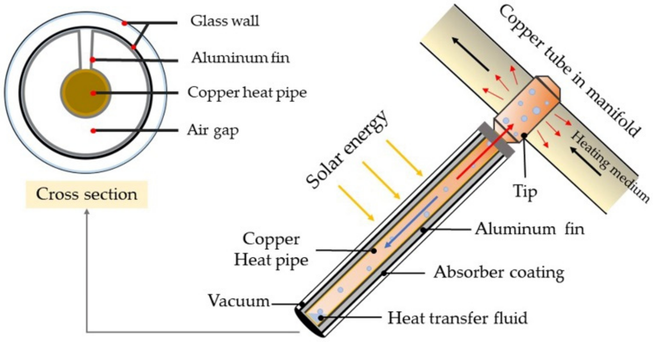
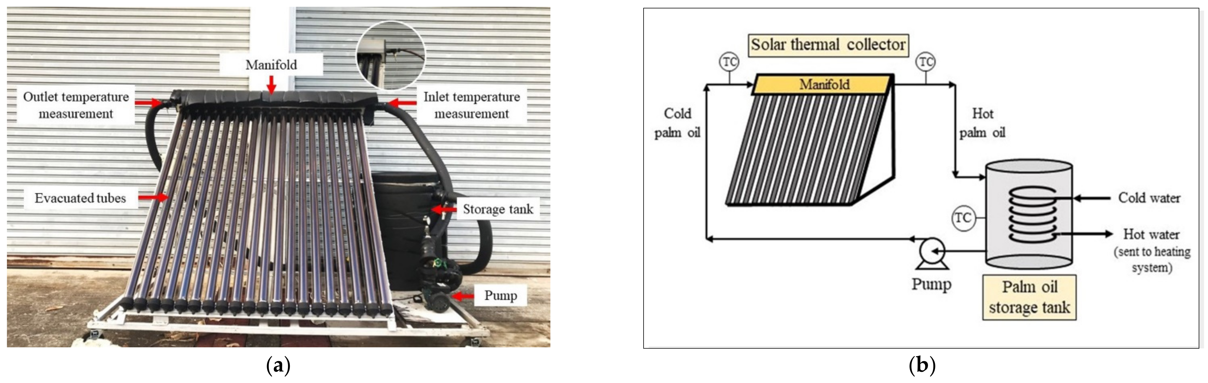
2.1. System Configuration
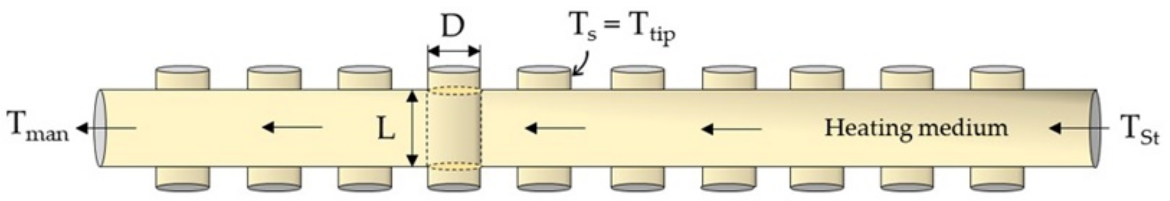
The principle of the ETSC is described in Figure 1. A conventional evacuated tube consists of concentric glass tubes, an aluminum fin, and a copper heat pipe. The space between inner and outer glass walls is vacuumed for preventing the heat loss. The inner glass wall is coated by the selective absorber coating for absorbing the solar radiation. The solar radiation transforms to thermal energy to heat the heat transfer fluid stored inside the copper heat pipe. The aluminum fin is placed inside the space to make a contact between the concentric glass tube and heat pipe wall and, therefore, increase thermal conduction surface area. The heat transfer fluid is responsible for receiving thermal energy from the outside, then evaporating to the heat pipe tip, exchanging heat with heating medium flowing through the manifold. After transferring its latent heat to the heating medium, the heat transfer fluid vapor is condensed and flows down to the bottom of copper heat pipe to receive heat again. Eventually, the heating medium will be used for such a thermally applications.

2.2. Calculation

Mechanistic ordinary differential equation model has been developed to predict the performance of the ETSC. The model is validated with the experimental data, then applied to study the feasibility of adapting the ETSC with a small-scale industry. The evacuated tubes and a storage tank are modelled separately.

2.2.1. Energy Transfer in the Evacuated-Tube Solar Collector System

The solar radiation absorbed by evacuated tubes absorber can be calculated by using Equation (1).
Q ˙ r a d = I A E T C
The heat transfer rate from the tubes’ tips in the manifold to the heating medium can be calculated by Equation (2).
Q ˙ E T C = m ˙ c p T m a n T S t = h A s Δ T l m
where Δ T l m is the log mean temperature difference between the tip and the heating medium calculated from Equation (3).
Δ T l m = T s T m a n T s T S t ln [ T s T m a n / T s T S t ]
Depending on the arrangement of the tips (20 rows in-line) as shown in Figure 2, the outlet temperature of the heating medium is calculated by Equation (4).
T m a n = T t i p T t i p T S t e x p A t i p h m ˙ c p
where A t i p = N π D L is the outer surface area of the tips contacting with heating medium.
Heat transfer coefficient ( h ) can be determined through Nusselt number as shown in Equation (5). The Nusselt number correlation followed the work of Zukauskas et al. [21].
N u = h D k =   C R e m P r n P r / P r s 0.25
where C = 0.9, m = 0.40 and n = 0.36 for 0 ≤ Re ≤ 100.
The energy balance of the heating medium storage tank can be expressed as Equation (6). The heating medium temperature in the storage tank (TSt) is assumed to be equal to the inlet temperature of heating medium to manifold.
d Q S t d t = Q ˙ E T C Q ˙ l o s s
where Q S t and Q ˙ l o s s can be expressed as Equations (7) and (8), respectively.
d Q S t d t = ρ V c p d T S t d t
Q ˙ l o s s = U A T T S t T a
Therefore, the change in storage temperature can be calculated by Equation (9).
ρ V c p d T S t d t = m ˙ c p T m a n T S t U A S t T S t T a
Finally, the efficiency of ETSC can be calculated by using Equation (10).
η = m ˙ c p T m a n T S t I A E T C

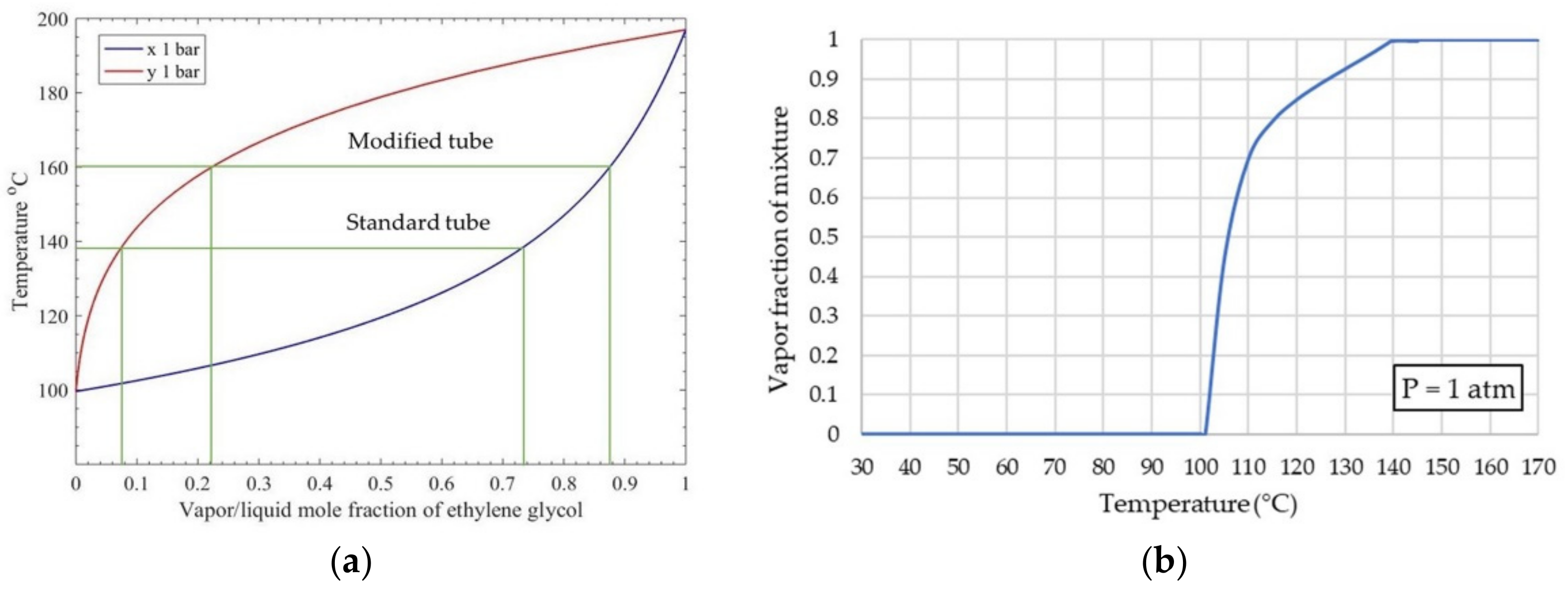
2.2.2. Vapor/Liquid Equilibrium (VLE)

The vapor/liquid equilibrium (VLE) theory is used to investigate phase change behavior of the heat transfer fluid. The binary VLE relation is summarized in Equation (11) [22]. This relation combines the vapor phase fugacity coefficients ( ϕ ^ i ) and the liquid phase activity coefficients ( γ i ) to provide non-ideal gas and non-ideal solution. The fugacity coefficients and the activity coefficients of ethylene-glycol and water are obtained by using SRK cubic equation of state and UNIQUAC functional-group activity coefficients (UNIFAC), respectively [22].
y i Φ i P = x i γ i P i s a t
where Φ i is a ratio of fugacity coefficient, which can be expressed as:
Φ i ϕ ^ i v ϕ i s a t exp V i l P P i s a t R T
The saturated pressure of pure specie, i can be calculated by using Antoine equation as shown below:
ln P i s a t = A B T + C
where A, B and C are parameters corresponding to each substance.
Finally, the binary VLE relation is applied to calculate T-xy diagram for investigating the phase change behavior.

3. Experimental Setup

A set of ETSC was installed at King Mongkut’s Institute of Technology Ladkrabang, Bangkok (13°43′ N, 100°46′ E), as shown in Figure 3. The experimental set included 20 evacuated-tubes containing 10 mol% of ethylene-glycol in water as a heat transfer fluid; palm oil was used as heating medium receiving thermal energy from the tips of the evacuated tubes placed inside the manifold, then transferring to store in the storage tank. The characteristic of the ETSC system is shown in Table 1. The ETSC was operated by turning on the pump to allow for the palm oil to circulate throughout the system between 9.00 a.m. to 4.00 p.m. daily during the observation period. The palm oil circulation rate was fixed at 0.032 kg/s with varying the volumes of 50, 80, 100, 120, 140, and 160 L stored inside the storage tank. The inlet and outlet temperatures of the palm oil, the storage tank temperature and the solar intensity were recorded every hour. The system was shut down between 4.00 p.m. to 0.00 a.m. and temperature change during this period was recorded for evaluating heat loss from the storage tank. Type-k thermocouples (±0.4% error) and a solar intensity meter (TM-206, ±5% error, TENMARS ELECTRONICS, Taiwan) were used to measure temperatures and solar intensity, respectively. The experiments were carried out on 6 consecutive days with similar solar intensity and ambient temperature in November 2020. The average solar intensities of these days were approximately 828.36–870.93 W/m2. The experimental data are used to validate the mathematical model.
In the part of inner structure modification, the inner structure of evacuated tube was modified to promote heat transfer to the copper heat pipe. Conventionally, the aluminum fin was placed inside the evacuated tube as shown in Figure 4a. To modify this tube, stainless-steel scrubbers were inserted in the gap between the evacuated tube and the copper heat pipe to increase heat conduction surface area. Void fraction and weight of stainless-steel scrubbers placed in the evacuated tubes were approximately 2% and 109.7 g, respectively. A set of experiment consists of 2 standard tubes and 2 modified tubes, as shown in Figure 4b. Type k thermocouples (±0.4% of error) were attached at the heat pipe tips. Even though the temperature of the heat transfer fluid throughout the heat pipe may not be uniform and equal to the temperature of the outer tip wall, to simplify the calculation and with the limitation of experimental data collection, the temperature of the heat transfer fluid, i.e., 10 mol% of ethylene-glycol in water stored inside the heat pipe is assumed to be equivalent to the temperature of the heat pipe tip. The solar intensity, heat pipe tip temperature, and ambient temperature were recorded during 9.00 a.m. to 4.00 p.m. Data of the heat pipe tip temperature were used to investigate performance of ETSC and phase change behavior of the heat transfer fluid in the vapor/liquid equilibrium (VLE) theory.

4. Results and Discussion

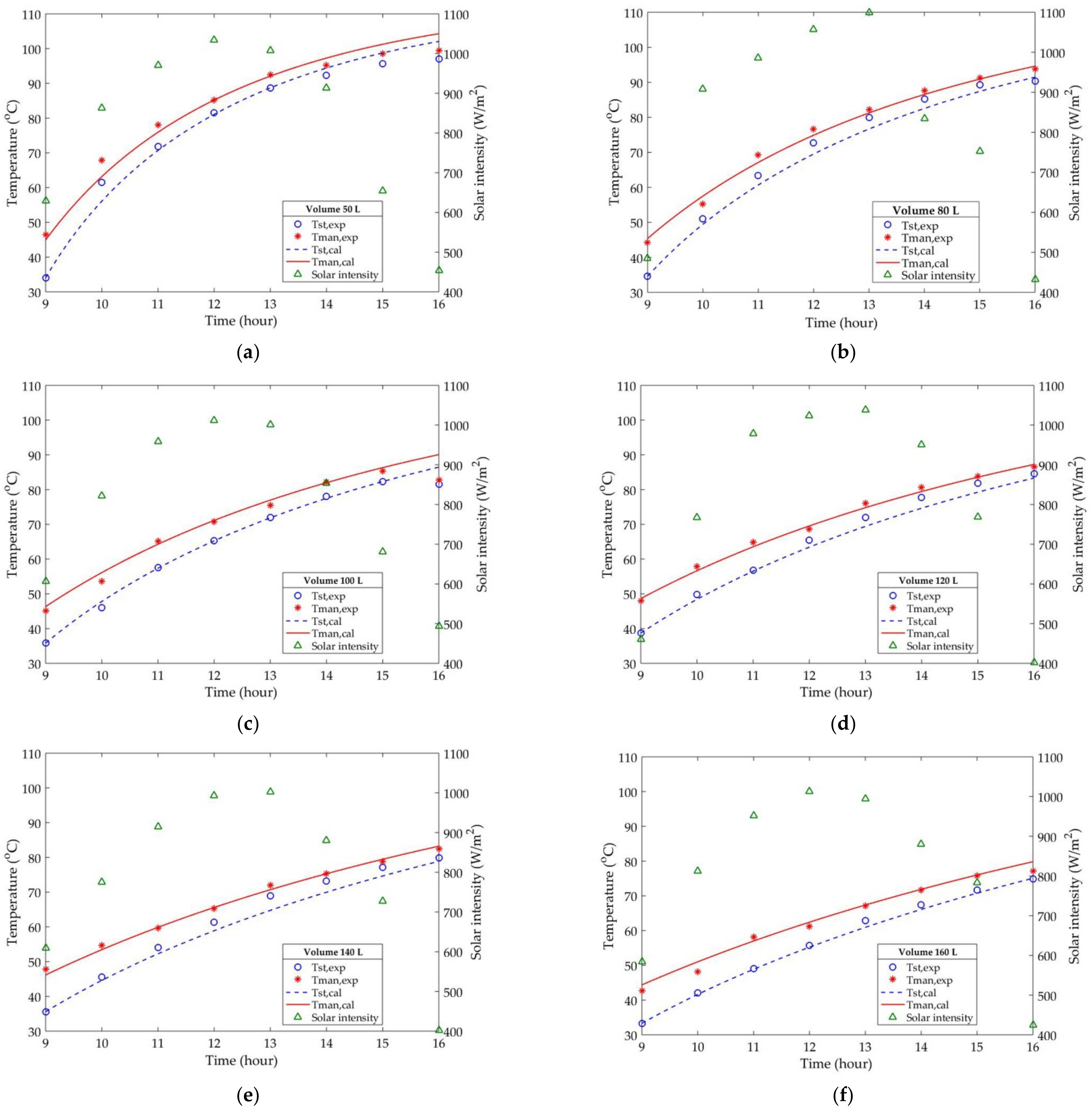
4.1. Experimental Results

The mathematical model was developed to facilitate the study of operating and climatic condition effects on the performance of ETSC. Furthermore, the validated model could be applied to study the feasibility of adapting the ETSC with thermally application in a small-scale industry. In this work, the palm oil was used as a heating medium in the 20-ETSC system. Figure 5a–f show the manifold and storage temperatures with different storage volumes of palm oil experimentally and theoretically and the solar intensity. The storage volume was one of the parameters affecting the performance of the ETSC.
With 50 L and 80 L storage volumes as shown in Figure 5a,b, the storage temperature increases rapidly between 9:00 a.m. to 1:00 p.m. since the rise of solar radiation in this period directly affected the temperature of heat transfer fluid inside the copper heat pipe. The heat transfer fluid took 1 h for heating up to steady state temperature at approximately 140 °C. In addition, as above storage volumes were small, they needed small amount of thermal energy to heat the whole palm oil up and, therefore, the temperature of the palm oil inside the storage tank increased rapidly. The maximum storage temperatures of 50 L and 80 L reached at 4:00 p.m. are 97 °C and 90.4 °C, respectively. Although the temperature increase rate of the 50 L and 80 L storage volume was very fast, the heat storing capacity was inferior. The heat loss quantity of the 50 L and 80 L was 83.84 W and 43.50 W, respectively.
On the other hand, with 100 L, 120 L, 140 L, and 160 L storage volumes, as shown in Figure 5c–f, the results show that the storage temperature steadily increases throughout the measured period because the heat storing capacity of such storage volumes were large and, thus, needed more thermal energy to heat more volume up. The maximum storage temperatures of 100 L, 120 L, 140 L, and 160 L are 81.6 °C, 84.6 °C, 79.9 °C, and 74.8 °C, respectively.
It can be seen that the storage temperature of 50 L at 4:00 p.m. in Figure 5a drops and the maximum storage temperature of 100 L in Figure 5c is less than that of 120 L which is against the fact that less storage volume should provide higher maximum temperature. These are because the limitation on controlling climatic condition to be equivalent for every experiment leading to the lower solar intensity during 1:00 p.m. to 4:00 p.m. at the day of the 50 L and 100 L palm oil experiments were conducted comparing with the other days. Moreover, the trend of storage and manifold temperatures of 140 L and 160 L, as shown in Figure 5e,f could be increased further. However, the quantity of solar radiation during the day was not enough to drive the ETSC for both storage volumes.
The selection of optimal storage volume with size of the ETSC could lead to the increase in ETSC performance. The 120 L storage volume was a suitable volume for 20-ETSC system which provided 11.06 MJ of heat storage with about 30% of efficiency.

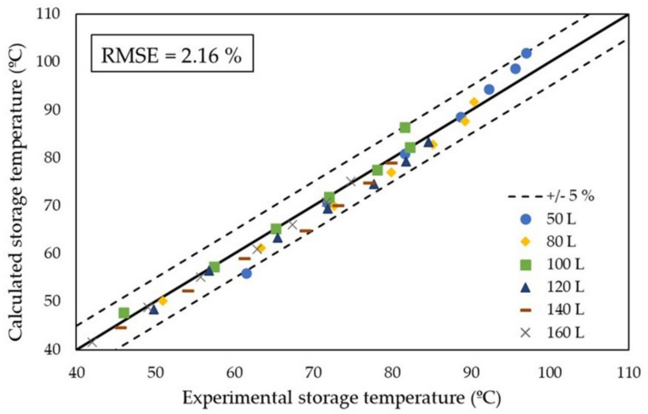
4.2. Model Validation

The validation of the model was performed by comparing the temperatures of the palm oil in the storage tank obtained from the calculation with those from experiments Initial palm oil temperature was about the ambient temperature at the day the experiment was carried out, explicit 4th order Runge–Kutta formula was applied to solve the differential equations expressed in Section 2.2.1. The 6 sets of experimental data varying storage volumes of palm oil were used for model validation as displayed in Figure 6. The results show that the overall average deviation in terms of RMSE is 2.16%; whereas the 50 L set exhibits the maximum average deviation of 3.07%. The low RMSE values indicate that this model was fit enough with validation data and hence could be used to evaluate effects of operating and climatic condition on the performance of ETSC and further applied for the ETSC system design integrated in small-scale industries.

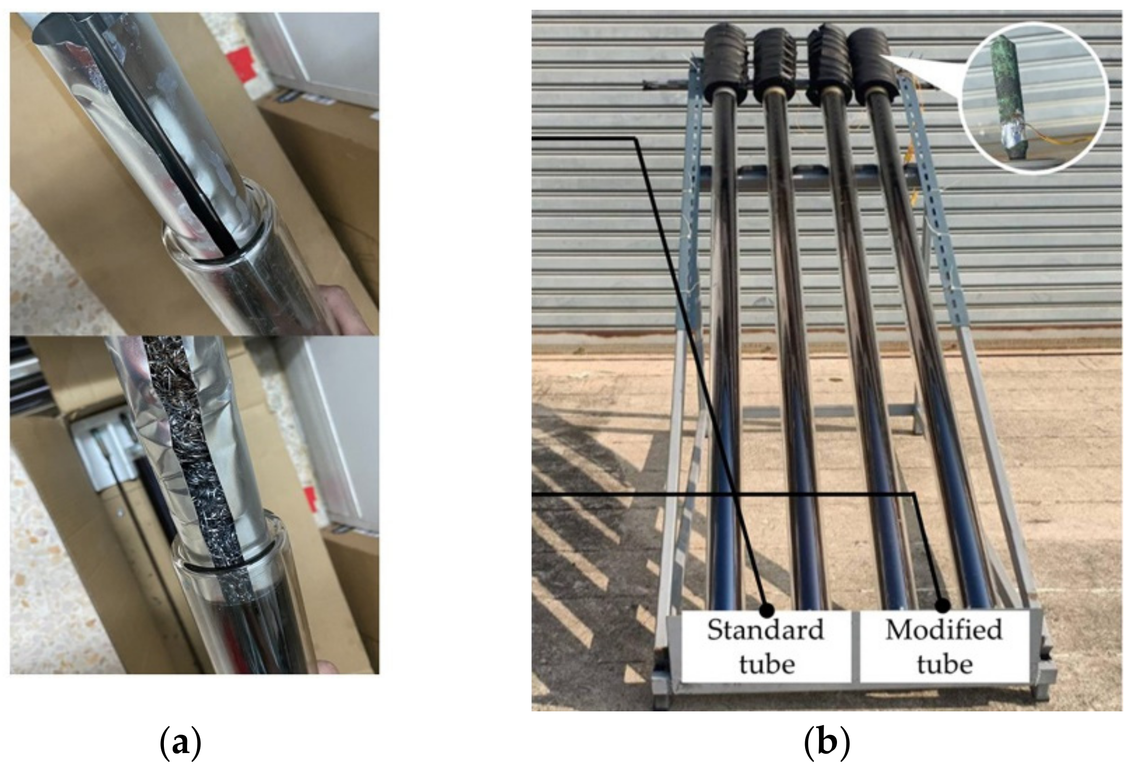
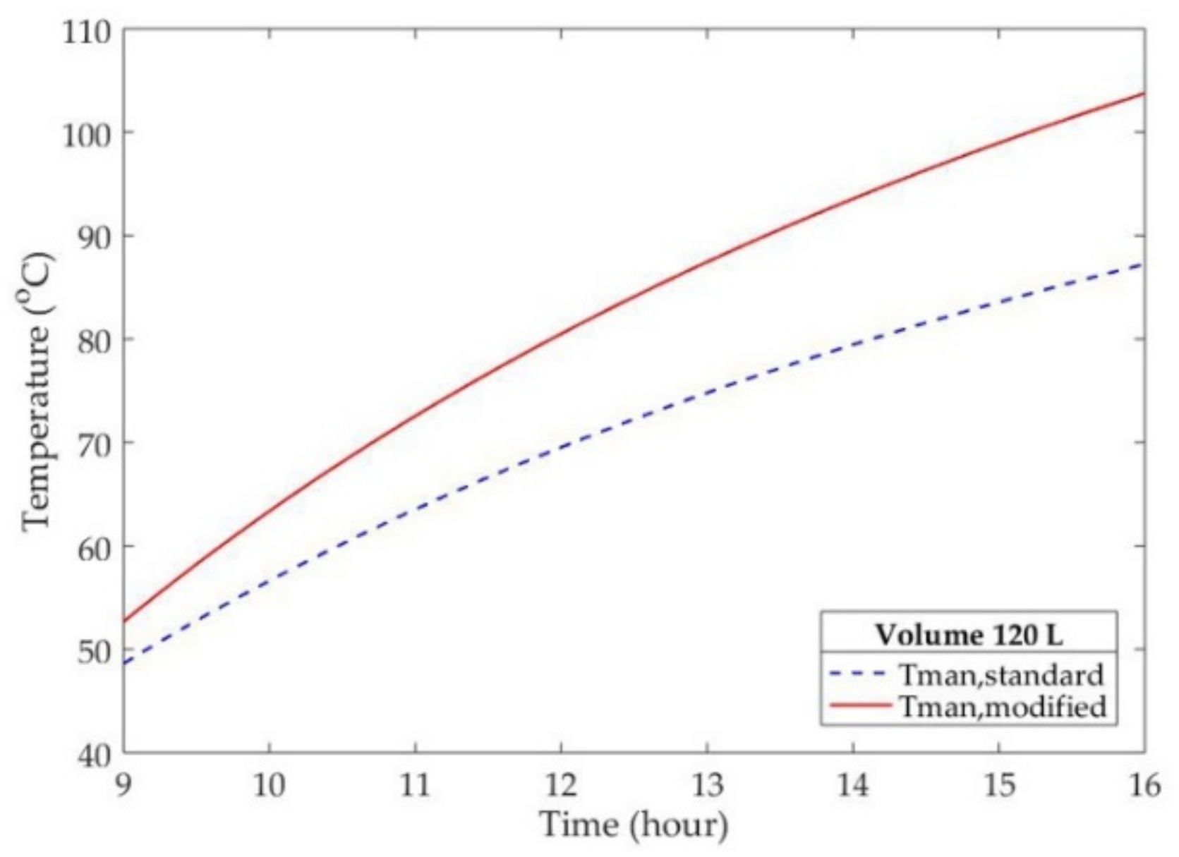
4.3. Evacuated Tube Modification

The heat transfer fluid is a key component used to drive the ETSC cycle. One simple way to improve the ETSC performance is by increasing the rate of heat transfer from inner glass wall to heat transfer fluid inside the heat pipe. Achieving higher heat transfer fluid temperature leads to the increase in heat storing rate of heating medium. As shown in Figure 1, there is a gap between the aluminum fin folded around the heat pipe. The gap of circular aluminum fin contained air which the thermal conductivity is 0.03 W/m·K. It indicates that the ability of heat conduction of air was lower than metals. Therefore, in this work, stainless-steel scrubbers, a common and low-cost material, were used to promote heat transfer rate by inserting them in the gap of the circular fin to increase heat conduction surface area.
The experimental results corresponding to the observation of the temperature of heat pipe tips of standard and modified evacuated tubes during the day is illustrated in Figure 7. The Figure 7 show that the solar intensity during the day is fluctuated because the sky was sometimes unclear. The temperatures of heat pipe tips of the standard tube and modified tube sharply increase between 9:15 a.m. to 10:15 a.m. During 11:24 a.m. to 12:19 a.m., the temperature of both tubes dramatically drops which is consistent with the solar intensity trend and then the temperature turns to increase until reaches steady temperature at 12:44 a.m. to 4:06 p.m. The heating time of standard and modified tubes for heating the heat pipe tip from ambient temperature to the steady temperature level is approximately 60 min. The average temperature of modified tube (160.32 °C) was approximately 20 °C more than a standard tube (138.71 °C). These temperatures were used to investigate phase change behavior of the heat transfer fluid by the VLE theory by assuming that: (1) the temperature of the heat pipe tip is approximately equivalent to the temperature of the heat transfer fluid inside the heat pipe, (2) the temperature drop between the bottom and the tip of the heat pipe is neglected, (3) pressure drop from vapor flow is neglected. The T-x,y diagram of 10 mol% of ethylene-glycol in water at 1 atm calculated by using the binary VLE relation is represented in Figure 8a. With this T-x,y diagram mole fractions of ethylene-glycol at any particular temperature in equilibrium can be identified. At 138.71 °C, the 0.1 mol of ethylene-glycol consists of 0.73 of liquid mole fraction ( x 1 ) and 0.09 of vapor mole fraction ( y 1 ) of ethylene-glycol; the 0.9 mol of water consists of 0.27 of liquid mole fraction ( x 2 ) and 0.91 of vapor mole fraction ( y 2 ) of water. Therefore, the vapor fraction and liquid fraction of the mixture are 0.986 and 0.002, respectively. On the other hand, at 160.32 °C, the 10 mol% of ethylene-glycol in water consist of 0.87 of x 1 , 0.26 of y 1 , 0.13 of x 2 and 0.74 of y 2 . The vapor fraction of mixture increases to 1 which shows that the stainless-steel scrubbers could promote the heat transfer from inner glass wall through aluminum fin to the copper heat pipe excellently. Figure 8b shows the summary of vapor fraction of 10 mol% of ethylene-glycol in water from calculation at different temperature. At the beginning, the heat transfer fluid absorbs the thermal energy in sensible heat form until 100 °C, boiling point of water. Then, the heat transfer fluid absorbs large amounts of the thermal energy from vaporization during 100 °C to 140 °C which the T-x,y diagram explains that the water will start vaporizing before ethylene-glycol. The minimum temperature that 10 mol% of ethylene-glycol in water at 1 atm completely vaporizes is 140 °C. However, the pressure drop and temperature drop could occur due to effect of evaporation and condensation of the heat transfer fluid leading to vapor flow and the difference of temperature inside the heat pipe. Therefore, the experiment may be designed to evaluate this factor in the future.
Overall heat transfer coefficient as shown in Table 2 was calculated for investigating the performance of heat transfer from the inner glass wall to the inner heat pipe wall. The overall heat transfer coefficient was determined from the thermal resistance of symmetry cylindrical layer. The total thermal resistance was a series network of the individual thermal resistances, consisting of thermal resistance of copper heat pipe layer, thermal resistance of inner aluminum fin layer, thermal resistance of air layer (convection), and thermal resistance of outer aluminum fin layer. In case of modified tube, the thermal resistance of stainless-steel scrubber was added into the total thermal resistance in parallel with the thermal resistance of air layer. The two assumptions for this calculation are: (1) the heat transfer surface area and the difference of temperature between inner glass wall and inner heat pipe wall are assumed constant, and (2) the thermal conductivity and heat transfer coefficient are constant. The results show that the stainless-steel scrubbers could reduce thermal resistance of the air led to shorter heating time.
The mathematical model was used to evaluate the effect of modifying inner structure of evacuated tube on the performance of ETSC. The 20-standard and modified evacuated tubes were observed. The climatic and operating conditions were based on the experimental data of 120 L palm oil case. The initial temperature of palm oil and the flow rate were 38.7 °C and 0.032 kg/s, respectively. The solar intensity and the ambient temperature were fixed at the average values of 848.86 W/m2 and 30 °C, respectively. Figure 9 shows that when a set of modified evacuated tube is operated, the palm oil temperature leaving the manifold at 9.00 a.m. increases from 48.63 °C to 52.67 °C. The heating medium energy production rate increased from 382.19 W to 515.82 W. The efficiency of 20-standard and 20-modified evacuated tubes solar collector were 30.02% and 40.51%, respectively. The efficiency of evacuated tube was improved by 34.96%.

4.4. Application

The model was applied to evaluate the feasibility of using the ETSC as water heating system in a food and beverage industry. Table 3 shows a typical hot water demand in the food and beverage industry [23]. It is appeared that 2419 kg of 60 °C hot water is required, which is equivalent to 45 m2 of standard solar collecting area capacity. Therefore, 3 parallel sets of a 100-tube ETSC system operated 8 h daily would be required. This system can generate 2482 L of hot water per day at 60 °C. The thermal energy produced by the ETSC system is around 27 MWh/year, which equal to USD 3000 per year of electricity cost. The capital investment of ETSC is USD 16,000 [24]; therefore, the breakeven of the system is approximately 5.06 years. On the other hand, a reduction by 20% of the number of tubes in the same production rate can be gained by using the modified tubes. The capital investment of ETSC will be saved by USD 3000. The breakeven of this system is approximately 4.09 years. However, the monthly average solar intensity should be concerned because it would vary according to climate condition. The system should be designed to support the lower average solar intensity periods or co-generated with main heat generator in industry.

5. Conclusions

The mechanistic model was developed and successfully validated with the experimental results with the overall average deviation in terms of RMSE of 2.16%. This model was used to predict the performance of the modified ETSC system and evaluate the feasibility of applying the ETSC in a small-scale industry. The stainless-steel scrubbers could improve the performance of the evacuated tube solar thermal absorber excellently, as it could increase the overall heat transfer coefficient by 10 times of the standard tube. The average temperature of modified tube tip (160.32 °C) was approximately 20 °C more than standard tube tip. The 20-modified ETSC provided 34.96% increase in efficiency compared with 20-standard ETSC in the same climatic and operating condition. The modified ETSC system was theoretically applied to generate the hot water in the food and beverage industry. This system could produce thermal energy of approximately 27 MWh/year and reduce the total number of tubes by 20% compared with standard ETSC system in the same production rate which could save the capital investment for USD 3000 which could shorten the breakeven of this system by almost 1 year.

Author Contributions

Conceptualization, R.S. and W.C.-a.; methodology, R.S. and W.C.-a.; software, R.S. and A.A.; validation, R.S.; formal analysis, R.S.; investigation, W.C.-a.; resources, P.P.; data curation, S.S.; writing—original draft preparation, R.S.; writing—review and editing, A.A. and W.C.-a.; visualization, R.S.; supervision, W.W., A.A., and W.C.-a.; project administration, W.C.-a. All authors have read and agreed to the published version of the manuscript.

Funding

This research was funded by King Mongkut’s Institute of Technology Ladkrabang, grant number 2564-02-01-011.

Institutional Review Board Statement

Not applicable.

Informed Consent Statement

Not applicable.

Data Availability Statement

Data are contained within the article.

Acknowledgments

The authors would like to thank King Mongkut’s Institute of Technology Ladkrabang for the financial support [grant number 2564-02-01-011] and sincerely thank to RANO TECH CO., LTD for supplying the evacuated tube solar collector in the experiment.

Conflicts of Interest

The authors declare no conflict of interest.

Nomenclature

AArea (m2)Symbols
cpSpecific heat capacity (J/kg·K)πPi
DDiameter of tip (m)ρDensity (kg/m3)
hHeat transfer coefficient (W/m2·K)μViscosity (Pa·s)
ISolar intensity (W/m2)ηEfficiency
kThermal conductivity (W/m·K)Difference
LLength of tube (m)ΦRatio of fugacity coefficient
m ˙ Mass flow rate (kg/s)ϕFugacity coefficients
NNumber of tubesγActivity coefficients
NuNusselt numberSubscripts
PPressure (atm)aAmbient
PrPrandtl numberETCEvacuated tuber solar collector
Q ˙ Heat transfer rate (W)lossHeat loss
RGas constant (J/mol⋅K)manOutlet from manifold
ReReynolds numberradRadiation
TTemperature (°C or K)sSurface
TlmLog mean temperature (°C or K) StStorage
UOverall heat transfer coefficient (W/m2·K)tipTip
vVelocity (m/s)iComposition
VVolume of heating medium (m3)Superscripts
x,yMole fractionlLiquid
satSaturated
vVapor

References

  1. Areas with Solar Power Potential. Available online: http://weben.dede.go.th/webmax/content/areas-solar-power-potential (accessed on 30 August 2019).
  2. Ma, L.; Lu, Z.; Zhang, J.; Liang, R. Thermal Performance Analysis of the Glass Evacuated Tube Solar Collector with U-Tube. Build. Environ. 2010, 45, 1959–1967. [Google Scholar] [CrossRef]
  3. Abd-Elhady, M.S.; Nasreldin, M.; Elsheikh, M.N. Improving the Performance of Evacuated Tube Heat Pipe Collectors Using Oil and Foamed Metals. Ain Shams Eng. J. 2018, 9, 2683–2689. [Google Scholar] [CrossRef]
  4. Heyhat, M.M.; Valizade, M.; Abdolahzade, S.; Maerefat, M. Thermal Efficiency Enhancement of Direct Absorption Parabolic Trough Solar Collector (DAPTSC) by Using Nanofluid and Metal Foam. Energy 2020, 192, 1–23. [Google Scholar] [CrossRef]
  5. Sarafraz, M.M.; Tlili, I.; Baseer, M.A.; Safaei, M.R. Potential of Solar Collectors for Clean Thermal Energy Production in Smart Cities Using Nanofluids: Experimental Assessment and Efficiency Improvement. Appl. Sci. 2019, 9, 1877. [Google Scholar] [CrossRef] [Green Version]
  6. Olia, H.; Torabi, M.; Bahiraei, M.; Ahmadi, M.H.; Goodarzi, M.; Safaei, M.R. Application of Nanofluids in Thermal Performance Enhancement of Parabolic Trough Solar Collector: State-of-the-Art. Appl. Sci. 2019, 9, 463. [Google Scholar] [CrossRef] [Green Version]
  7. Sarafraz, M.M.; Tlili, I.; Tian, Z.; Bakouri, M.; Safaei, M.R.; Goodarzi, M. Thermal Evaluation of Graphene Nanoplatelets Nanofluid in a Fast-Responding HP with the Potential Use in Solar Systems in Smart Cities. Appl. Sci. 2019, 9, 2101. [Google Scholar] [CrossRef] [Green Version]
  8. Ghaderian, J.; Sidik, N.A.C.; Kasaeian, A.; Ghaderian, S.; Okhovat, A.; Pakzadeh, A.; Samion, S.; Yahya, W.J. Performance of Copper Oxide/Distilled Water Nanofluid in Evacuated Tube Solar Collector (ETSC) Water Heater with Internal Coil under Thermosyphon System Circulations. Appl. Therm. Eng. 2017, 121, 520–536. [Google Scholar] [CrossRef]
  9. Mujawar, N.H.; Shaikh, S.M. Thermal Performance Investigation of Evacuated Tube Heat Pipe Solar Collector with Nanofluid. Int. J. Eng. Sci. Res. Technol. 2016, 5, 824–827. [Google Scholar] [CrossRef]
  10. Valizade, M.; Heyhat, M.M.; Maerefat, M. Experimental Comparison of Optical Properties of Nanofluid and Metal Foam for Using in Direct Absorption Solar Collectors. Sol. Energy Mater. Sol. Cells 2019, 195, 71–80. [Google Scholar] [CrossRef]
  11. Papadimitratos, A.; Sobhansarbandi, S.; Pozdin, V.; Zakhidov, A.; Hassanipour, F. Evacuated Tube Solar Collectors Integrated with Phase Change Materials. Sol. Energy 2016, 129, 10–19. [Google Scholar] [CrossRef] [Green Version]
  12. Selvakumar, P.; Somasundaram, P.; Thangavel, P. Performance Study on Evacuated Tube Solar Collector Using Therminol D-12 as Heat Transfer Fluid Coupled with Parabolic Trough. Energy Convers. Manag. 2014, 85, 505–510. [Google Scholar] [CrossRef]
  13. Kim, Y.; Seo, T. Thermal Performances Comparisons of the Glass Evacuated Tube Solar Collectors with Shapes of Absorber Tube. Renew. Energy 2007, 32, 772–795. [Google Scholar] [CrossRef]
  14. Shah, L.J.; Furbo, S. Vertical Evacuated Tubular-Collectors Utilizing Solar Radiation from All Directions. Appl. Energy 2004, 78, 371–395. [Google Scholar] [CrossRef]
  15. Luu, M.T.; Milani, D.; Nomvar, M.; Abbas, A. Computer-Aided Design for High Efficiency Latent Heat Storage—A Case Study of a Novel Domestic Solar Hot Water Process. Comput. Aided Chem. Eng. 2017, 40, 1153–1158. [Google Scholar] [CrossRef]
  16. Al-Falahi, A.; Alobaid, F.; Epple, B. A New Design of an Integrated Solar Absorption Cooling System Driven by an Evacuated Tube Collector: A Case Study for Baghdad, Iraq. Appl. Sci. 2020, 10, 3622. [Google Scholar] [CrossRef]
  17. Ghoneim, A.A. Optimization of Evacuated Tube Collector Parameters for Solar Industrial Process Heat. Int. J. Energy Environ. Res. 2017, 5, 55–73. [Google Scholar]
  18. Isafiade, A.J.; Kravanja, Z.; Bogataj, M. Design of Integrated Solar Thermal Energy System for Multi-Period Process Heat Demand. Chem. Eng. Trans. 2016, 52, 1303–1308. [Google Scholar] [CrossRef]
  19. Picón-Núñez, M.; Martínez-Rodríguez, G.; Fuentes-Silva, A.L. Targeting and Design of Evacuated-Tube Solar Collector Networks. Chem. Eng. Trans. 2016, 52, 859–864. [Google Scholar] [CrossRef]
  20. Kotb, A.; Elsheniti, M.B.; Elsamni, O.A. Optimum Number and Arrangement of Evacuated-Tube Solar Collectors under Various Operating Conditions. Energy Convers. Manag. 2019, 199, 112032. [Google Scholar] [CrossRef]
  21. Cengel, Y.A.; Ghajar, A.J. Heat and Mass Transfer Fundamental and Application, 5th ed.; McGraw-Hill Education: New York, NY, USA, 2016; Volume 283, pp. 424–454. [Google Scholar]
  22. Smith, J.M. Introduction to Chemical Engineering Thermodynamics, 8th ed.; McGraw-Hill Education: New York, NY, USA, 1950; Volume 27, pp. 450–508. [Google Scholar]
  23. Solar Cell. Available online: http://www2.dede.go.th/solarcell/Datafiles/InstallByPanya.pdf (accessed on 8 September 2020).
  24. Grewal, S.; Grewal, S. Product and Process Design Principles, 3rd ed.; Welter, J., Ed.; Donald Fowley: Hoboken, NJ, USA, 2011; pp. 534–597. [Google Scholar]
Figure 1. Principle of an evacuated-tube solar collector.
Applsci 11 04100 g001
Figure 2. Arrangement of the tips in in-line in flow direction.
Applsci 11 04100 g002
Figure 3. (a) A set of evacuated-tube solar collector system in the experiment; (b) Schematic of evacuated-tube solar collector.
Applsci 11 04100 g003
Figure 4. (a) Cross-sectional view of the standard and modified tubes; (b) Experimental set up.
Applsci 11 04100 g004
Figure 5. The storage and manifold temperatures of heating medium from the experiment (dots) and the mathematical model (lines) at different times of the operation. (a) 50 L; (b) 80 L; (c) 100 L; (d) 120 L; (e) 140 L; (f) 160 L.
Applsci 11 04100 g005
Figure 6. Comparison of the storage temperatures of heating medium between the experiment and the model with different storage capacities.
Applsci 11 04100 g006
Figure 7. Comparison of the heat pipe tip temperature of the standard tube and modified tube.
Applsci 11 04100 g007
Figure 8. (a) T-x,y diagram of 10 mol% of ethylene-glycol in water at 1 atm; (b) Relation between vapor fraction of 10 mol% of ethylene-glycol in water and temperature at 1 atm.
Applsci 11 04100 g008
Figure 9. The simulated manifold temperatures corresponding to standard tube and modified tube.
Applsci 11 04100 g009
Table 1. Computational parameters of evacuated-tube solar collector system.
Evacuated TubeHeat Transfer Fluid
Inner diameter0.047mComponent10 mol% of ethylene-glycol (EG) in water
Outer diameter0.058m
Length1.80mVolume5mL
Surface area0.15m2MW of EG62.07 g/mol
Number of tubes20tubesDensity of EG1.11kg/m³
Copper heat pipeAir layer
Thermal conductivity401W/m·KThermal conductivity0.03W/m·K
Inner diameter0.012mHeat transfer coefficient10W/m2·K
Outer diameter0.014mThickness0.016m
Aluminum finStainless-steel scrubber
Thermal conductivity237W/m·KThermal conductivity15.1W/m·K
Thickness0.5mmVoid fraction 0.02
Heating medium storage tankCopper heating medium tube
Heating mediumPalm oil Inner diameter 0.019m
Tank diameter0.58mOuter diameter0.022m
Tank height0.76m
Overall heat transfer coefficient, U 0.72W/m2·K
Table 2. Summary of standatd evacuated tube and modifided evacuated tube performance.
Standard TubeModified Tube
Heating time 160 min60 min
Steady temperature of tip138.71 °C160.32 °C
Vapor fraction at tip0.9861
Overall heat transfer coefficient per unit area, UA30.30 W/K306.74 W/K
1 Heating time is time taking to heat the tip from ambient temperature to steady temperature.
Table 3. The design parameters of the ETCS applied for the water heating system in a food and beverage industry.
Target
Consumption2482 L/day
Operating temperature60 °C
DesignStandard ETSCModified ETSC
Heating mediumPalm oilPalm oil
Mass flow rate0.18 kg/s0.18 kg/s
Inlet temperature70 °C70 °C
Outlet temperature80 °C80 °C
Production rate27 MWh /year27 MWh /year
Number of tubes300 tubes (Area = 45 m2)240 tubes (Area = 36 m2)
Arrangement3 parallel sets of 100-tube3 parallel sets of 80-tube
Capital investment$16,000$13,000
Breakeven5.06 years4.09 years
Publisher’s Note: MDPI stays neutral with regard to jurisdictional claims in published maps and institutional affiliations.

