
The Effect of Subgrade Coefficient on Static Work of a Pontoon Made as a Monolithic Closed Tank


Department of Construction and Geoengineering, Faculty of Environmental and Mechanical Engineering, Poznan University of Life Sciences, Piatkowska Street 94, 60-649 Poznan, Poland
Appl. Sci. 2021, 11(9), 4259; https://doi.org/10.3390/app11094259
Submission received: 9 March 2021
/
Revised: 30 April 2021
/
Accepted: 4 May 2021
/
Published: 8 May 2021
(This article belongs to the Section Civil Engineering)
Abstract
:This article presents the effect of taking into account the subgrade coefficient on static work of a pontoon with an internal partition, made in one stage and treated computationally as a monolithic closed rectangular tank. An exemplary pontoon is a single, ready-made shipping element that can be used as a float for a building. By assembling several floats together, the structure can form a floating platform. Due to the increasingly violent weather phenomena and the necessity to ensure safe habitation for people in countries at risk of inundation or flooding, amphibious construction could provide new solutions. This article presents calculations for a real pontoon made in one stage for the purpose of conducting research. Since it is a closed structure without any joint or contact, it can be concluded that it is impossible for water to get inside. However, in order to exclude the possibility of the pontoon filling with water, its interior was filled with Styrofoam. For static calculations, the variational approach to the finite difference method was used, assuming the condition for the minimum energy of elastic deflection during bending, taking into account the cooperation of the tank walls with the Styrofoam filling treated as a Winkler elastic substrate and assuming that Poisson’s ratio ν = 0. Based on the results, charts were made illustrating the change in bending moments at the characteristic points of the analysed tank depending on acting loads. The calculations included hydrostatic loads on the upper plate and ice floe pressure as well as buoyancy, stability and metacentric height of the pontoon. The aim of the study is to show a finished product—a single-piece pontoon that can be a prefabricated element designed for use as a float for “houses on water”.
1. Introduction
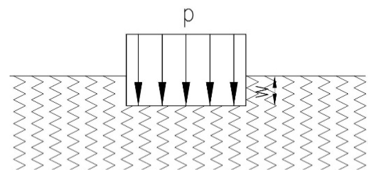
Monolithic rectangular tanks can be used as single, ready-made elements serving as floats for buildings or as components for constructing floating platforms intended, among other purposes, for mooring vessels. Recently, stationary floating structures have seen an increased global interest [1]. It can be estimated that there are 40,000 to 50,000 of these objects in the world [2]. Such interest should not come as a surprise, as design solutions supporting amphibious construction can be applied in a wide manner. This is due to numerous reasons, ranging from the interest in the land–-water interface as a very attractive site for the tourism industry to the increased expansion of living space in densely populated countries. Another developmental contributor to amphibious construction might be progressive climate change, which causes heavy rainfall, inundation and flooding. It is anticipated that, by the end of this century, water levels will have risen by a meter [3]. Amphibious construction is one of several methods oriented towards urbanisation of floodplains [4,5]. Floats can be made of various materials depending on their design purpose. The market offers floats made of plastic, metal or reinforced concrete. Reinforced concrete pontoons consist of a box filled with polystyrene and a cover plate installed later. The solution always poses a risk of inaccuracies in assembly, subsequent leaks and shorter use [6]. A more advantageous solution, although more computationally and executively challenging, is to design and produce a tank as a single, ready-made element, possible to be built without any additional construction work [7,8]. Typisation and prefabrication are two of the most important directions in construction today. By optimizing prefabricated structures, the aim is to achieve the best material consumption while ensuring the load-bearing capacity of the structure and—consequently—economic benefits. The pontoon mentioned in this article was a single-piece tank made in one stage, i.e., a closed box without any contacts or joints. This excluded the possibility of leakage or flooding of the structure. To minimize the risk of the pontoon filling with water, it was tightly filled with Styrofoam. The literature on the subject provides few publications on closed tasks made in one stage [7,8] and taking into account the effect of the substrate, which—for the pontoon in question—was Styrofoam [9]. Since the technical literature has not yet provided solutions for this type of tank taking into account the effect of its substrate, it was decided that a dedicated numerical analysis would be performed for the purposes of this study. In building structures, plates often rest on a substrate made of materials other than the buildings. The most commonly applied substrate scheme is a Winkler elastic substrate [10]. This static scheme is a system of infinitely closely arranged springs of equal stiffness. The Winkler model specifies a substrate with the use of one parameter, assuming that the working load is equal to the product of plate deflection and substrate stiffness. Thus, the deflection of the substrate occurs only on the surface on which the load acts. Figure 1 schematically presents the Winkler elastic substrate, while Equation (1) provides the aforementioned correlation [11].
where
- p—load (kN/m2),
- w—deflection (m), and
- Kz—substrate stiffness (kN/m3).
Another model of the two-parameter Winkler-type substrate is proposed in [12], where instead of springs, a system of densely spaced bars with a specific bending stiffness value was introduced. In the Filonenka–Borodić model, it is assumed that a Winkler-type substrate is covered on its upper surface by an unlimited membrane, tensioned with evenly distributed tensile forces [11]. The model of Vlasov and Leontiev is one of the more accurate models of substrate mapping. It consists of determining an elastic layer, the deflection of which is determined approximately using detailed material data describing this layer [11]. Two-parameter substrate models such as Vlasov, Pasternak or Gorbunov–Posadov systems of equations are much less frequently used, due to the difficulty in making calculations with their use [13,14,15,16]. The differential equation of a plate resting on a one-parameter Winkler substrate is described by Equation (2).
where
- D = —plate flexural rigidity,
- —Laplacian,
- —bi-Laplacian,
- ν—Poisson’s ratio,
- h—plate thickness,
- w—plate deflection,
- αt—coefficient of thermal expansion,
- q—load perpendicular to the central surface of the plate,
- ΔT—difference in temperature between lower plate Td and upper plate Tg determined by correlation: ΔT = Td − Tg, αt is the coefficient of thermal expansion of the plate material,
- Kz—subgrade stiffness reaction.
The Winkler-type substrate model may raise doubts in terms of the assumption that the substrate dislocates only at points where the load acts. In fact, if the substrate on which the structure is placed is continuous, displacements also occur outside its load zone. Although other, more accurate models do not have this drawback, they usually lead to the same differential Equation (2), and the difference lies in the method through which their coefficients are determined.
The purpose of this article is to analyse the statics of closed rectangular tanks with an internal partition, the distribution of internal forces and their effect on the value of bending moments, assuming the cooperation with the Styrofoam filling treated as an elastic substrate. Additionally, the buoyancy and stability of the pontoon were checked against standard guidelines from different countries. This work is of an application nature, and the idea of this article is to develop a ready-made building element that can be built in without any additional construction work.
2. Materials and Methods
2.1. Calculation Method
This work uses the finite difference method to solve the determined systems of differential equations. Although this method is less frequently used, apart from the finite element method, it can be successfully applied in static calculations. It is a universal way of solving differential equations under certain boundary conditions, consisting in replacing the derivatives present in the equation and boundary conditions by appropriate difference ratios. Since the function describing the plate deflection is not known, unknown values are assumed to be surface ordinates in a finite number of points (nodes), which are located at the intersection points of the created division mesh for the object being calculated [11]. Tanks are complex structures, characterized by spatial work; therefore, too much simplification in calculations or failure to take into account actual dimensions or material constants may lead to erroneous results. Currently, with the possibility of using widely understood computer-aided design, the calculation process is becoming less and less complicated. However, most computational programs are based on the finite element method. This work used the finite difference method as an alternative and as an effective means to solve the determined systems of differential equations. The subject matter has been taken up in numerous outstanding and fundamental scientific works [17,18,19,20,21,22,23,24,25,26,27,28,29,30]. The method has been used in calculations regarding plate structures [9,31,32], tanks [7,8,33] or surface girders. This work also used the condition for the minimum energy of elastic deformation accumulated while undergoing bending in the plate resting on the elastic substrate. The calculations were carried out traditionally, discretizing the object and creating systems of equations. Then, using proprietary calculation solutions, the results were obtained, i.e., deflections at each point of the division mesh. The energy functional is described by Equation (3).
where A is the plate area and other components of the formula are described in (2). Further analysis was based on the adopted designations (4):
On the assumption that the Poisson’s ratio was v = 0 and excluding the parameter of temperature, the energy functional changed its form into Equation (3) [11].
2.2. Verification of Pontoon Buoyancy and Stability
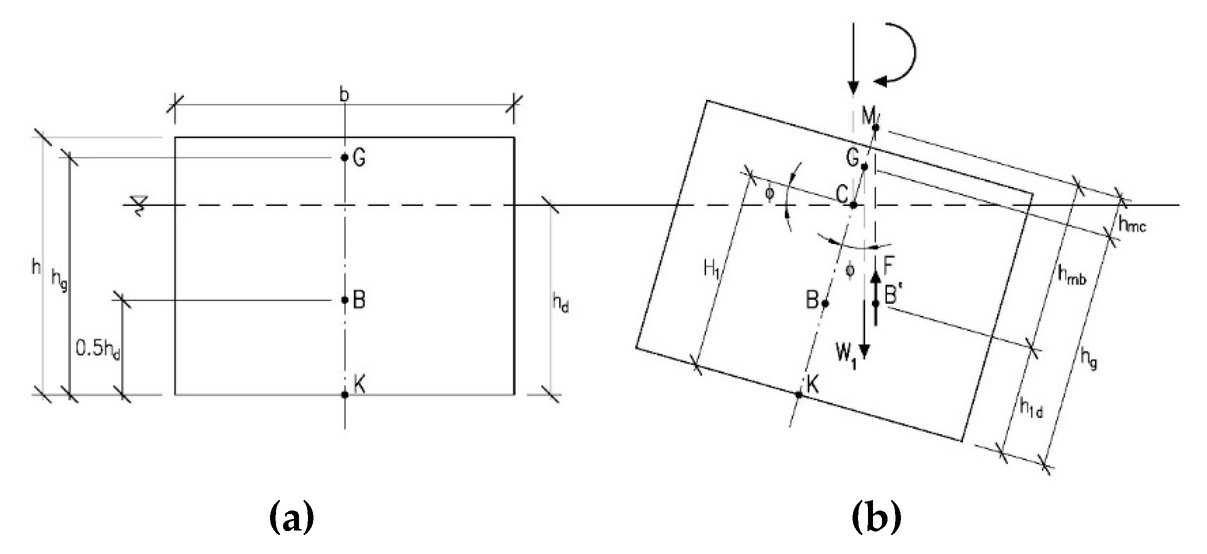
The dimensioning of building structures is performed by the limit state method. Therefore, pontoons, apart from meeting the first limit state—load capacity—must also comply with the second limit, state serviceability. For this type of structure, it is the fulfilment of buoyancy and stability requirements. Pontoon buoyancy is determined by calculating its immersion depth, i.e., freeboard (the vertical distance from the top edge of the pontoon (deck) to the surface of water). Its stability is determined by the location of the metacentric point and tilt angle. The metacentre is the theoretical intersection point of the buoyant vector of the tilted floating vessel and its plane of symmetry. Its distance from the centre of gravity of the vessel (e.g., pontoon), the metacentric height, is a measure of its stability [6]. If the metacentre is above the centre of gravity, i.e., the metacentric height is positive, then the balance of the vessel is stable. If the metacentric distance is negative, then the equilibrium is unstable. According to recommendations adopted in Poland, in compliance with [34] when designing platforms loaded with crowds, it should be assumed that the load is 3.0 kPa, whereas the tilt angle should be verified at 1.0 kPa applied to half the width of the platform. The results of the stability and metacentric height calculations presented later in the article were obtained on the basis of the procedures provided for in Australian Standard AS 3962-2001 [35]. The schematic drawings of the pontoon (cross sections) used to verify its buoyancy and stability are shown in Figure 2a,b, respectively [8].
3. Results
3.1. Static Analysis of the Pontoon
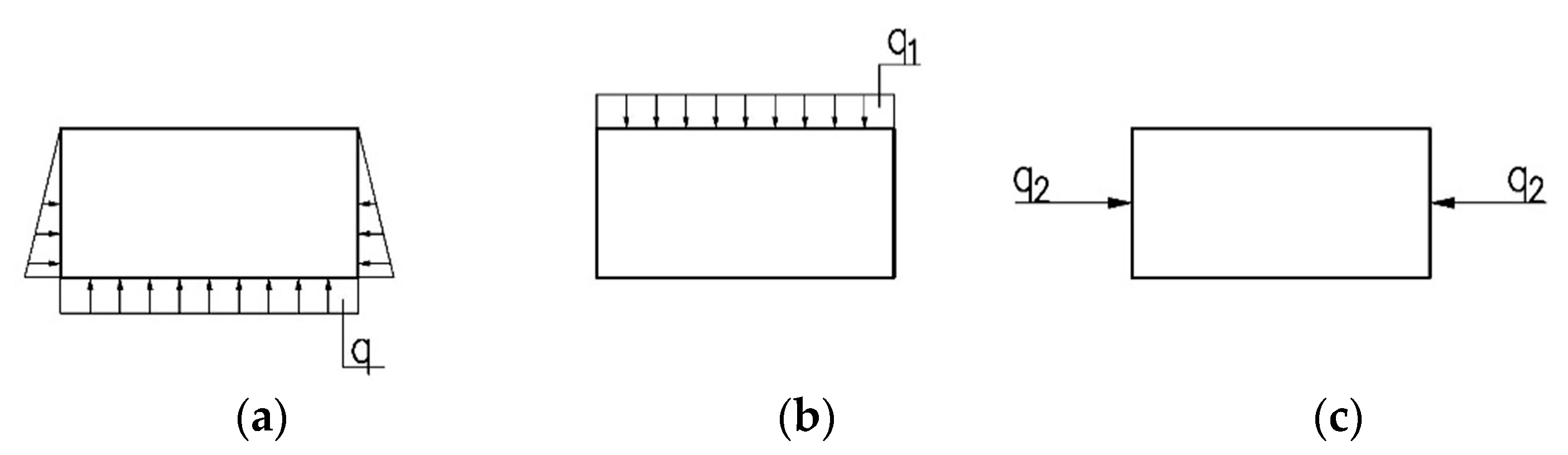
For the purpose of this work, appropriate static calculations were made in order to verify the effect that an internal elastic substrate has on the value and distribution of bending moments in closed rectangular tanks. Calculations used the finite difference method in variational approach and were made for a closed rectangular tank with axial dimensions lx, ly and lz being at a 4:1:0.5 ratio, respectively. The value of substrate stiffness (Styrofoam) was assumed as Kz = 5000 kN/m3. The tank featured an internal partition in the centre of its length. The discretization grid took into account the symmetry plane of the structure, and assuming that the mesh size was s = ly/12, the system of equations with 823 unknowns was obtained. The following loads were included: hydrostatic load acting on the tank walls, uniform load acting on the bottom (Figure 3a), uniform load acting on the upper plate of the tank (Figure 3b) and ice floe pressure acting on the circumference of the tank at half its height (Figure 3c).
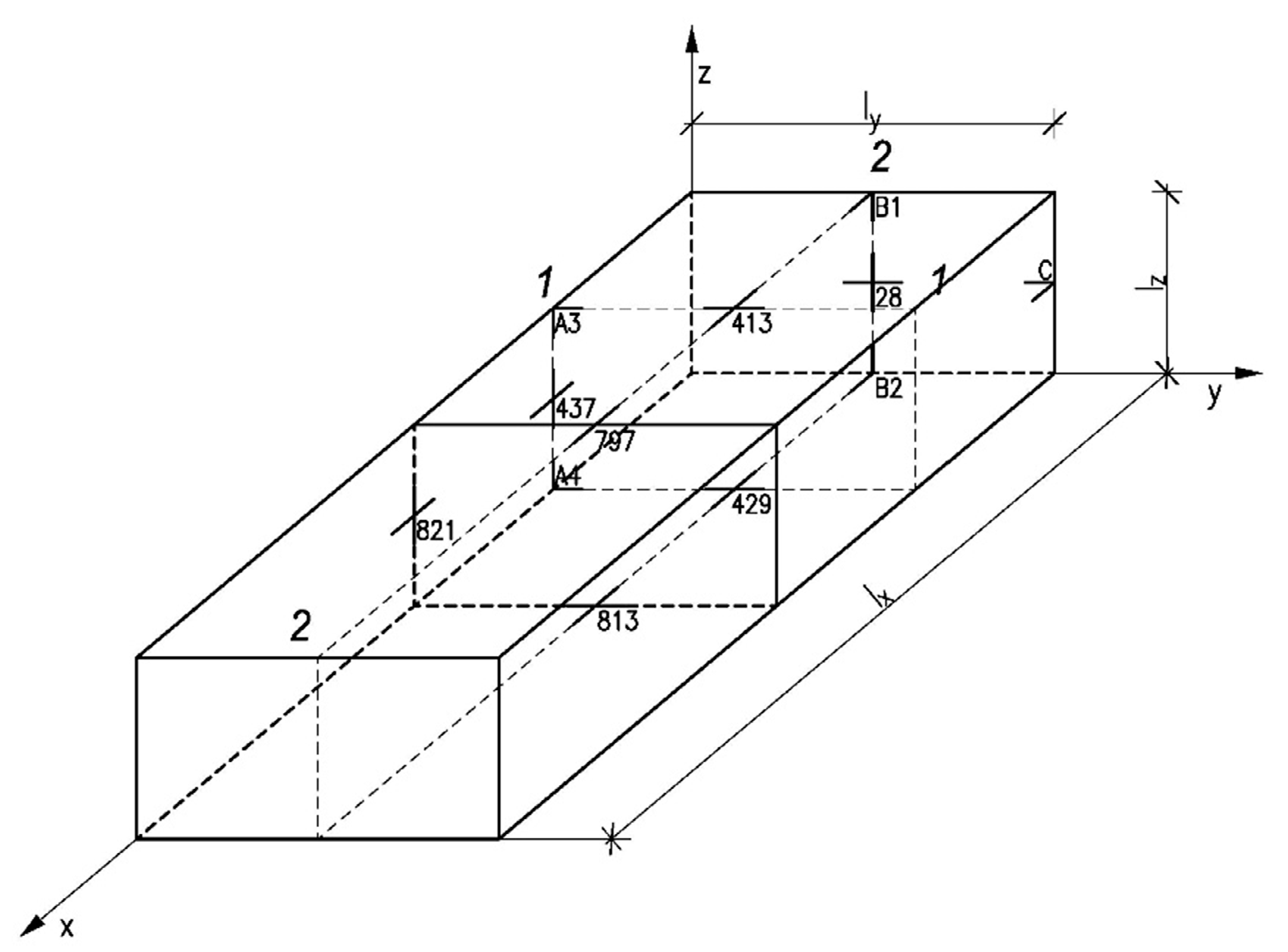
Figure 4 shows a schematic drawing of the pontoon with its internal partition with the numbering of points for which the article gives coefficients proportional to bending moments.
In order to create a new structural element that can be successfully used in construction and because the idea of this article is to apply the obtained numerical calculation results to practice, the specific dimensions of the pontoon were assumed. The dimensions enable its production, transport and use as a single element or as a connected floating platform, and they were adopted as length lx = 10 m, width ly = 2.5 m, height lz = 1.25 m, thickness of all walls h = 0.08 m and substrate shear modulus (Styrofoam) Kz = 5000 kN/m3.
The results of the calculation of coefficients proportional to the values of bending moments at select points for the pontoon with and without the cooperation with its elastic substrate are presented in Table 1. In order to analyse the effect of taking into account the substrate on the change in the values of deflections and bending moments, charts were drawn up showing the distribution of the values of bending moments in longitudinal and transverse sections (Figure 5, Figure 6, Figure 7 and Figure 8). The designations of points are in line with Figure 4, and as the most important, the hydrostatic load on the walls, the uniform load on the bottom of the pontoon and the uniform load of the top plate were selected.
By analysing the data obtained from the numerical calculations listed in Table 1, it can be concluded that, at each point of the partition grid as well as for each type of load, the bending moments are reduced, taking into account the elastic substrate. Hence, the tank components were assumed to rest on polystyrene, which while filling the inside of the tank, reduces the values of bending moments, which in turn are used to calculate the required reinforcement area for the reinforced concrete structure of the tank. The conclusions resulting from Table 1 can be used to support a decision to reduce the amount of reinforced steel used in the production process and thus for material and cost savings.
3.2. Calculation Results of Buoyancy and Stability
Following the recommendations of Australian standard AS 3962-2001 [35], the buoyancy for the analysed tank at self-load and at service load evenly distributed on the top plate, amounting to 3.0 kN/m2 was calculated. Additionally, the metacentric height and tilt angle were calculated at half load of the top plate equal to 1.0 kN/m2. Since the second limit state, i.e., serviceability, needed to be verified, it was necessary to assume for calculations the load coefficient γF = 1, in accordance with [36,37].
As earlier, for detailed calculations the following data was used: length lx = 10 m, width ly = 2.5 m, height lz = 1.25 m, thickness of tank walls and the upper plate h = 0.08 m, reinforced concrete class C35/45 and Styrofoam filling with a volumetric weight 0.45 kN/m3.
In order to reduce the tilt angle in the designed pontoon, the weight of the pontoon was increased. The calculations took into account an increase in the weight of the pontoon due to the water absorption of concrete, which is about 4–5%. Table 2 also shows the pontoon buoyancy and stability calculations, taking into account an increase in the pontoon’s weight caused by 5% concrete absorbability. The results of calculations are summarized in Table 2.
The presented calculations show that increasing the weight of the pontoon reduces the tilt angle. Therefore, if it was required to reduce the tilt angle to a value below 6°, the thickness of the bottom plate should be increased while maintaining the remaining parameters [8].
4. Discussion
The prefabricated pontoon analysed in the study as a ready-made element makes a good alternative to currently available reinforced concrete platforms, consisting of a box and a separate cover. The article presents the results of calculations made for a monolithic rectangular tank intended to be used as a pontoon. There are still problems related to the analysis, design and execution of concrete floating structures [38]. The literature on the subject provides few works related to this subject. This article presents a pontoon that was made on a 1:1 scale. The authors of [7] presented the series of closed tanks for use as a pontoon with the following axial dimensions: lx, ly and lz at a ratio of 1:1:0.5; lx, ly and lz at a ratio of 2:1:0.5; lx, ly and lz at a ratio of 3:1:0.5; and lx, ly and lz at a ratio of 4:1:0.5. However, the effect of Poisson’s ratio and the subgrade coefficient was not taken into account. When analysing the tanks of increasing length, it can be concluded that, for long tanks with size proportions lx, ly and lz at γ:1:0.5 for γ > 3; the effect of disturbances resulting from the gable walls’ load disappear in their central part; and the central part works similar to a closed frame, i.e., a rod system. The paper [8] shows the effect of the increasing values of bottom thickness on the values of deflections and moments. By thickening the bottom at all points of the calculated tanks, the following regularity was noticed: deflections decreased when the bottom plates became thicker. It was observed that the hydrostatic load acting on the tank walls and the uniform load acting on the bottom combined with an increase in bottom thickness led to an increase in bending moments acting in the middle of the bottom plate span towards a shorter span, while reducing bending moments at other points of the tank. In contrast, the uniform load acting on the upper plate led to an increase in bending moments, but only in the bottom, both for fastening moments and for the moment working in the centre of the plate towards a shorter span. Bending moments at other points of the tank practically did not change. Reference [9] indicates that taking into account the effect of the thermal insulation layer made of spray-applied polyurethane foam in the plate calculations causes that with an increase in the modulus of subgrade reaction, deflections and bending moments to decrease. Pontoons are structures exposed to numerous loads, difficult to define; therefore, conducting research on real-scale objects helps to understand the specifics of their structure [7,39]. The consideration of the Poisson’s ratio or subgrade coefficient in calculations has practically no effect on buoyancy and stability calculations. The tilt angles for the calculated pontoon were 7.0° and 6.92° (Table 2). According to the standard [36], the freeboard should be at least 0.05 m at a tilt angle not exceeding 6°. The standard [34] states that this angle should not exceed 10°. Simplified calculations are allowed by the standard [35] and then the tilt angle should not exceed 15°. The calculation procedure for the purpose of this article was carried out in accordance with [35]. Reference [40] relates to purposefulness of designing heavy floating systems. A pontoon should be of such height as to keep the deck above the water level and should be heavy enough to balance the upsetting moment in violent winds.
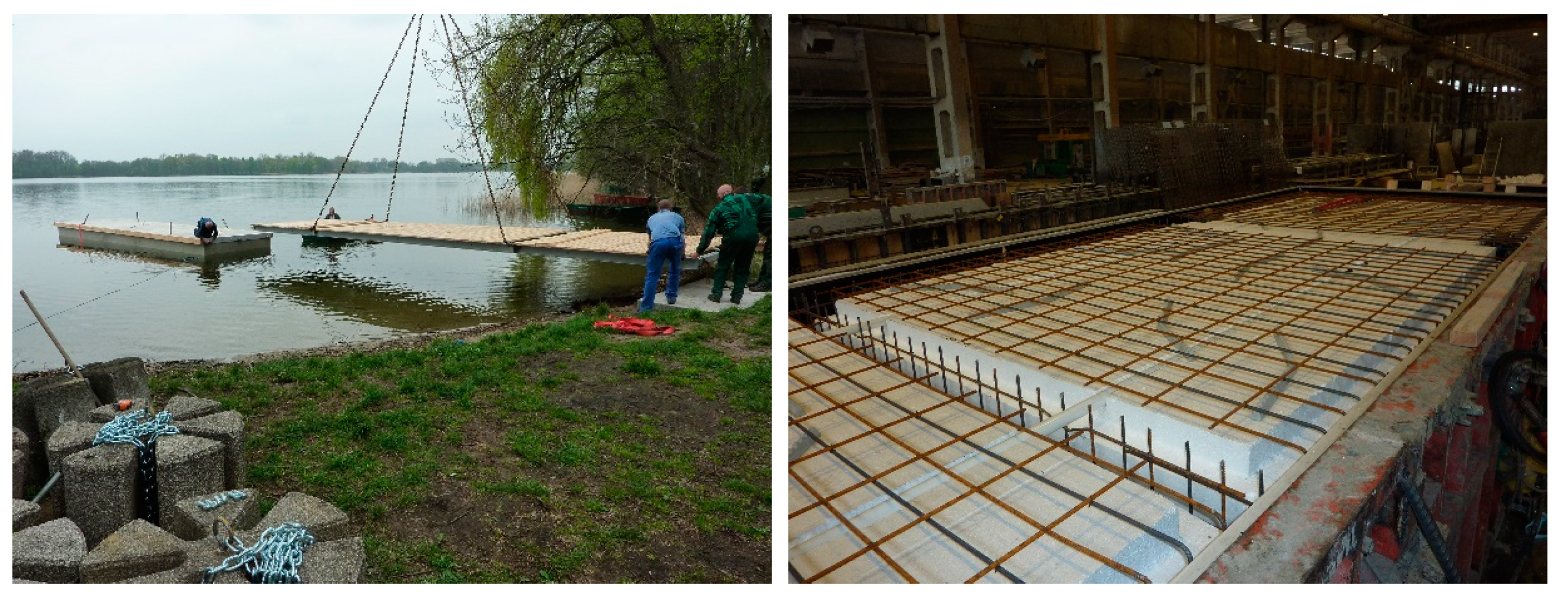
This article includes calculations for a unique rectangular tank with a partition in its centre, made at a 1:1 scale, for which the effect of filling with Styrofoam as an elastic substrate was taken into account. Figure 9 shows the pontoon during execution and launching.
5. Conclusions
The calculation results presented in the article were obtained using the finite difference method in variational approach, assuming Poisson’s ratio ν = 0 and subgrade coefficient Kz = 5000 kN/m3. The following real dimensions of the pontoon were adopted: length lx = 10 m, width ly = 2.5 m, height lz = 1.25 m and thickness of all walls h = 0.08 m.
Based on the analyses carried out, the following can be concluded:
- taking into account in calculations the cooperation of the tank walls with its elastic substrate filling reduces bending moments and, in some cases, changes the sign of bending moments (Table 1). For example, the bending moment Mx813 (according to designations in Figure 4) occurring in the middle of the bottom length, above the support, which due to the hydrostatic load acting on the walls and the bottom, without taking into account its elastic substrate, was Mx813= 10.24996 qs2 while, taking into account its elastic substrate, was reduced to Mx813 = 8.16864 qs2, so it decreased by 20%;
- taking into account in calculations an internal Styrofoam filling treated as an elastic substrate reduces the values of bending moments and consequently the area that requires necessary reinforcement and thus the solution becomes more financially beneficial;
- taking into account in calculations the cooperation of the pontoon’s structure with an internal filling does not affect its buoyancy and stability;
- the pontoon presented in the article can be a ready-made, prefabricated reinforced concrete shipping element, prepared to be built in at its final location, which can be used as a float in amphibious construction.
Funding
This research received no external funding.
Conflicts of Interest
The authors declare no conflict of interest.
References
- Wang, C.M. Great, Ideas Float on the Top. In Large Floating Structures: Technological Advances; Wang, C.M., Wang, B.T., Eds.; Springer: Berlin/Heidelberg, Germany, 2015; pp. 1–36. [Google Scholar]
- Holcombe, S. Applications and Huge Potential Demand for Amphibious Structures. In Proceedings of the First International Conference on Amphibious Architecture, Design & Engineering, Waterloo, ON, Canada, 25–28 June 2017; Volume 138. [Google Scholar]
- Nakajima, T.; Umeyama, M. A New Concept for the Safety of Low-lying Land Areas from Natural Disasters. J. Ocean Eng. Mar. Energy 2015, 1, 19–29. [Google Scholar] [CrossRef] [Green Version]
- Ostrowska-Wawryniuk, K.; Piątek, Ł. Lightweight Prefabricated Floating Buildings for Shallow Inland Waters. Design and Construction of The Floating Hotel Apartment in Poland. J. Water Land Dev. 2020, 44, 118–125. [Google Scholar] [CrossRef]
- Laks, I.; Walczak, Z.; Szymczak-Graczyk, A.; Ksit, B.; Mądrawski, J. Hydraulic and legal conditions for buildings in floodplains—A case study for the city of Kalisz (Poland). IOP Conf. Ser. Mater. Sci. Eng. 2019, 471, 102050. [Google Scholar] [CrossRef]
- Mazurkiewicz, B. Yacht Ports and Marinas. Design; Fundacja Promocji Przemysłu Okrętowego i Gospodarki Morskiej: Gdańsk, Poland, 2010. [Google Scholar]
- Szymczak-Graczyk, A. Floating platforms made of monolithic closed rectangular tanks. Bull. Pol. Acad. Sci. Tech. Sci. 2018, 66, 209–219. [Google Scholar] [CrossRef]
- Szymczak-Graczyk, A. Numerical Analysis of the Bottom Thickness of Closed Rectangular Tanks Used as Pontoons. Appl. Sci. 2020, 10, 8082. [Google Scholar] [CrossRef]
- Szymczak-Graczyk, A. “Numerical analysis of the impact of thermal spray insulation solutions on floor loading”. Appl. Sci. 2020, 10, 1016. [Google Scholar] [CrossRef] [Green Version]
- Winkler, E. Die Lehre von der Elastizität und Festigkeit; Dominicus: Prague, Czech Republic, 1867. [Google Scholar]
- Kączkowski, Z. Plates. Static Calculations; Arkady: Warszawa, Poland, 2000. [Google Scholar]
- Urbanowski, W. Case studies of bending a round plate connected to a flexible substrate of generalized properties. Zesz. Nauk. Politech. Warsz. 1956, 3, 33–61. [Google Scholar]
- Szcześniak, W.; Ataman, M. Vibration of beam resting on the inertial Vlasov-Leontiev foundation under impulse of force. Autobusy 2016, 3, 727–732. [Google Scholar]
- Wang, Y.H.; Tham, L.G.; Cheung, Y.K. Beams and plates on elastic foundations: A review. Prog. Struct. Eng. Mater. 2005, 7, 174–182. [Google Scholar] [CrossRef]
- Ryżyński, W.; Karczewski, B. Determination of calculation parameters of the layered substrate under industrial floors. Nowocz. Hale 2014, 5, 34–38. [Google Scholar]
- Korhan, O.; Ayse, T.D. Free vibration analysis of thick plates on elastic foundations using modified Vlasov model with higher order finite elements. Int. J. Econ. Manag. 2012, 19, 279–291. [Google Scholar]
- Gołaś, J. Introduction to the Theory of Plates; Opole University of Technology Publishing House: Opole, Poland, 1972. [Google Scholar]
- Donnell, L.H. Beams, Plates and Shells; McGraw-Hill: New York, NY, USA, 1976. [Google Scholar]
- Naghdi, P.M. The Theory of Shells and Plates; Handbuch der Physick: Berlin, Germany, 1972. [Google Scholar]
- Panc, V. Theries of Elastic Plates; Academia: Prague, Czech Republic, 1975. [Google Scholar]
- Timoshenko, S.; Woinowsky-Krieger, S. Theory of Plates and Coatings; Arkady: Warszawa, Poland, 1962. [Google Scholar]
- Szlilard, R. Theory and Analysis of Plates. Classical and Numerical Methods; Prentice Hall, Englewood Cliffs: Bergen, NJ, USA; Prentice-Hall: Upper Saddle River, NJ, USA, 1974. [Google Scholar]
- Ugural, A.C. Stresses in Plates and Shells; McGraw-Hill: New York, NY, USA, 1981. [Google Scholar]
- Wilde, P. Variational approach of finite differences in the theory of plate. In Proceedings of the Materials of XII Scientific Conference of the Committee of Science PZiTB and the Committee of Civil Engineering of Polish Academy of Sciences, Krynica, Poland, 12–17 September 1966. [Google Scholar]
- Tribiłło, R. Application of the generalized finite difference method for plate calculations. Arch. Inżynierii Lądowej 1975, 2, 579–586. [Google Scholar]
- Son, M.; Sang Jung, H.; Hee Yoon, H.; Sung, D.; Suck Kim, J. Numerical Study on Scale Effect of Repetitive Plate-Loading Test. Appl. Sci. 2019, 9, 4442. [Google Scholar] [CrossRef] [Green Version]
- Nowacki, W. Z zastosowań rachunku różnic skończonych w mechanice budowli. Arch. Mech. Stos. 1951, 3, 419–435. [Google Scholar]
- Rapp, B.E. Chapter 30—Finite Difference Method. In Microfluidics: Modelling, Mechanics and Mathematics, Micro and Nano Technologies; Rapp, B.E., Ed.; Elsevier: Amsterdam, The Netherlands, 2017; pp. 623–631. [Google Scholar] [CrossRef]
- Blazek, J. Chapter 3—Principles of Solution of the Governing Equations. In Computational Fluid Dynamics: Principles and Applications; Blazek, J., Ed.; Elsevier: Amsterdam, The Netherlands, 2015; pp. 29–72. [Google Scholar] [CrossRef]
- Sadd, M.H. Chapter 5—Formulation and Solution Strategies. In Elasticity, Theory, Applications, and Numerics; Sadd, M.H., Ed.; Academic Press, Elsevier: Cambridge, MA, USA, 2005; pp. 83–102. [Google Scholar] [CrossRef]
- Szymczak-Graczyk, A. Rectangular plates of a trapezoidal cross-section subjected to thermal load. IOP Conf. Ser. Mater. Sci. Eng. 2019, 603, 032095. [Google Scholar] [CrossRef]
- Numayr, K.S.; Haddad, R.H.; Haddad, M.A. Free vibration of composite plates using the finite difference method. Thin-Walled Struct. 2004, 42, 399–414. [Google Scholar] [CrossRef]
- Buczkowski, W.; Szymczak-Graczyk, A.; Walczak, Z. Experimental validation of numerical static calculations for a monolithic rectangular tank with walls of trapezoidal cross-section. Bull. Pol. Acad. Sci. Tech. Sci. 2017, 65, 799–804. [Google Scholar] [CrossRef] [Green Version]
- Z44, Zalecenia do Projektowania Marskich Konstrukcji Hydrotechnicznych, Z1–Z46; Studia i materiały, 21; Politechnika Gdańska, Katedra Budownictwa Morskiego: Gdańsk, Poland, 1997.
- AS 3962-2001: The Australian Standard: Guidelines for Design of Marinas; Standards Australia International Ltd.: Sydney, Australian, 2001.
- PN–EN 14504:2010: Inland Waterway Vessels. Floating Harbors. Requirements, Tests; Polish Standardization Committee: Warsaw, Poland, 2010.
- PN-EN 1992-1-1:2008 Eurocode 2. Design of Concrete Structures. Part 1-1. General Rules and Rules for Buildings; Polish Standardization Committee: Warsaw, Poland, 2008.
- Jiang, D.; Tan, K.H.; Wang, C.M.; Ong, K.C.G.; Bra, H.; Jin, J.; Kim, M.O. Analysis and design of floating prestressed concrete structures in shallow waters. Mar. Struct. 2018, 59, 301–320. [Google Scholar] [CrossRef]
- Seifa, M.S.; Inoue, Y. Dynamic analysis of floating bridges. Mar. Struct. 1998, 11, 29–46. [Google Scholar] [CrossRef]
- Karczewski, A.; Piątek, Ł. The Influence of the Cuboid Float’s Parameters on the Stability of a Floating Building. Pol. Marit. Res. 2020, 3, 16–21. [Google Scholar] [CrossRef]
Figure 1.
Winkler substrate model (drawn by the author).

Figure 2.
The schematic drawing of the pontoon under constant load (a) and the schematic drawing of the pontoon under constant and variable load (b), where G—gravity centre of the pontoon, B—buoyancy centre of the pontoon at rest, K—keel, hd—immersion due to the dead weight load, hg—location of the gravity centre, C—centre of the visible area of the water surface, M—metacentre, W1—total weight of constant and variable loads, B’—buoyancy centre of the loaded pontoon, F—floating forces in water, hmc—metacentric height above the gravity centre, hmb—metacentric height above the buoyancy centre, and h1d—height of the buoyancy centre.

Figure 3.
Schematic drawing of the hydrostatic load acting on the tank walls and the bottom (a), uniform load acting on the upper plate (b) and ice floe pressure (c), for which static calculations were made.
Figure 3.
Schematic drawing of the hydrostatic load acting on the tank walls and the bottom (a), uniform load acting on the upper plate (b) and ice floe pressure (c), for which static calculations were made.

Figure 4.
Schematic drawing of the tank with its internal partition with the numbering of points and cross sections.
Figure 4.
Schematic drawing of the tank with its internal partition with the numbering of points and cross sections.

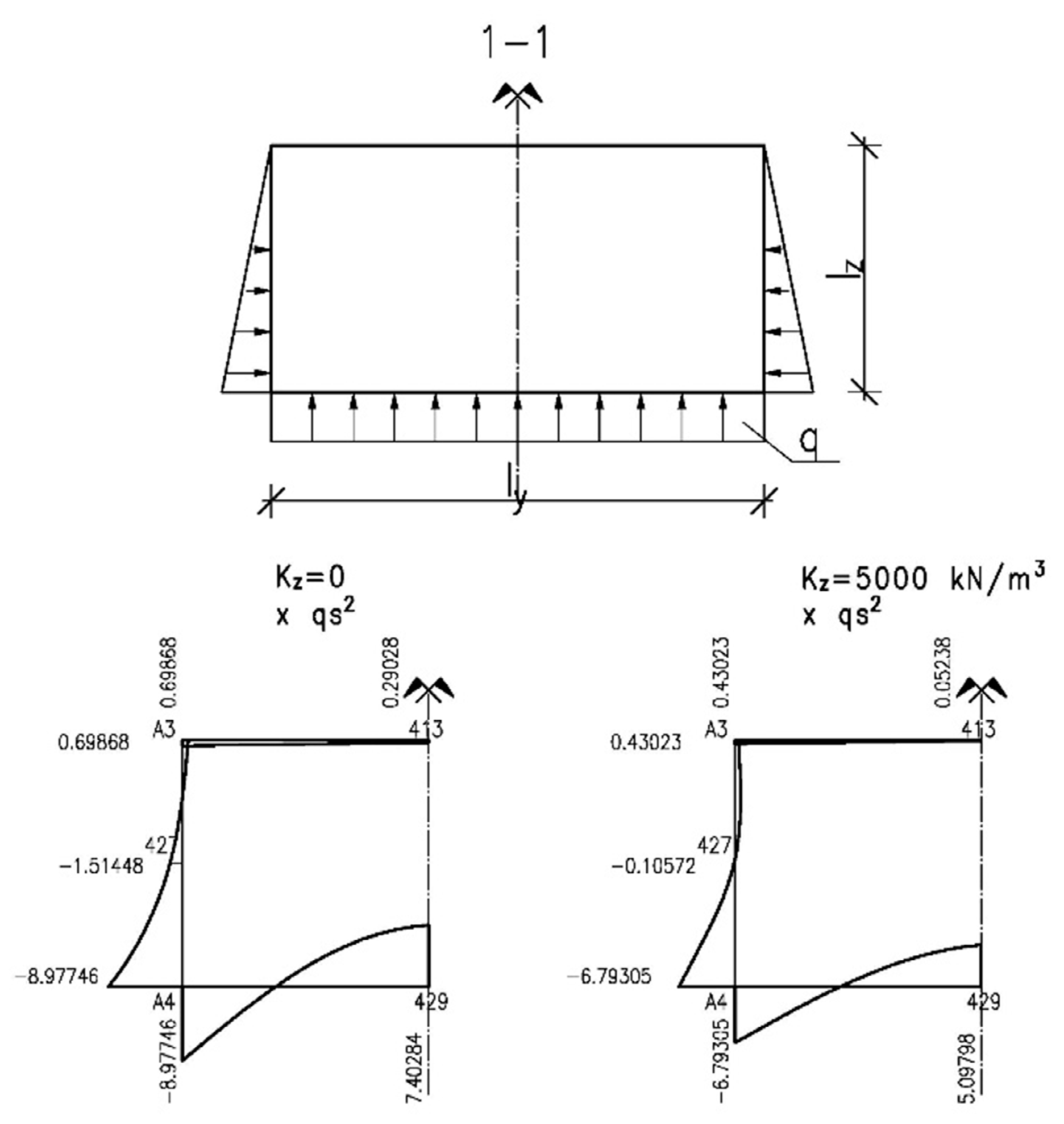
Figure 5.
Charts of bending moments due to the hydrostatic load of the walls and the uniform load of the bottom without taking into account the effect of an elastic substrate and for the Poisson’s ratio ν = 0 and taking into account the effect of an elastic substrate K = 5000 kN/m3 and for the Poisson’s ratio ν = 0 in cross section 1–1 (Figure 4).

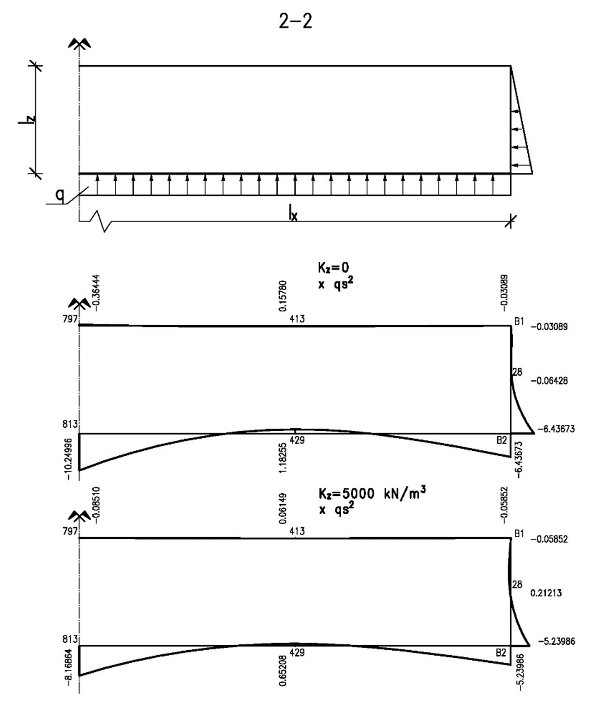
Figure 6.
Charts of bending moments due to the hydrostatic load of the walls and the uniform load of the bottom without taking into account the effect of an elastic substrate and for the Poisson’s ratio ν = 0 and taking into account the effect of an elastic substrate K = 5000 kN/m3 and for the Poisson’s ratio ν = 0 in cross section 2–2 (Figure 4). The internal partition lies in the symmetry axis.

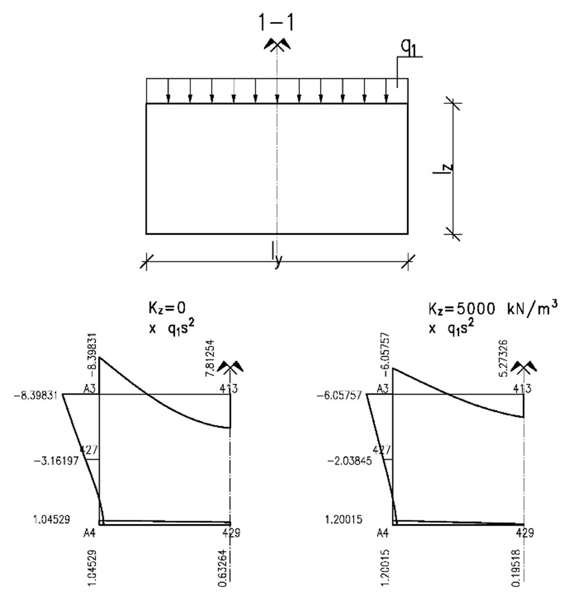
Figure 7.
Charts of bending moments due to the uniform load of the top plate without taking into account the effect of an elastic substrate and for the Poisson’s ratio ν = 0 and taking into account the effect of an elastic substrate K = 5000 kN/m3 and for the Poisson’s ratio ν = 0 in cross section 1–1 (Figure 4).

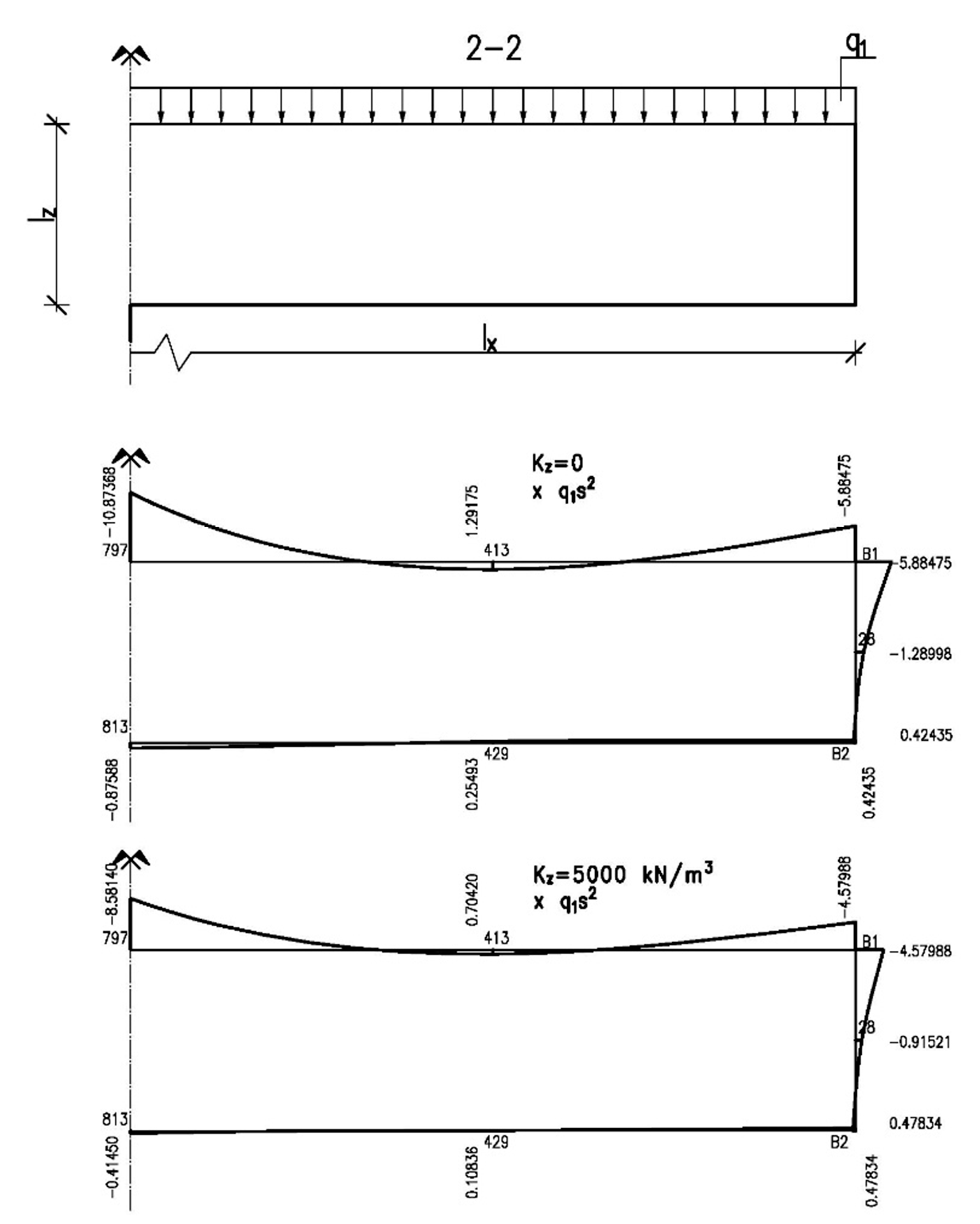
Figure 8.
Charts of bending moments due to the uniform load of the top plate without taking into account the effect of an elastic substrate and for the Poisson’s ratio ν = 0 and taking into account the effect of an elastic substrate K = 5000 kN/m3 and for the Poisson’s ratio ν = 0 in cross section 2–2 (Figure 4). The internal partition lies in the symmetry axis.

Figure 9.
The pontoon during execution with visible reinforcement and a partition in the centre (left) and during launching (right).
Figure 9.
The pontoon during execution with visible reinforcement and a partition in the centre (left) and during launching (right).


Table 1.
Comparison of coefficients proportional to the values of bending moments for the closed tank with an internal partition, with dimensions. lx = 10 m, ly = 2.5 m and lz = 1.25 m calculated with and without taking into account its elastic substrate. The size of mesh division s = ly/12.
Table 1.
Comparison of coefficients proportional to the values of bending moments for the closed tank with an internal partition, with dimensions. lx = 10 m, ly = 2.5 m and lz = 1.25 m calculated with and without taking into account its elastic substrate. The size of mesh division s = ly/12.
| Analyzed Value acc. Figure 4 |  |  |  |  |  |  |
|---|---|---|---|---|---|---|
| K = 5000 kN/m3 | K = 5000 kN/m3 | K = 5000 kN/m3 | ||||
| MA3 | 0.69868 qs2 | 0.43023 qs2 | −8.39831q1s2 | −6.05757 q1s2 | −0.27892 q2s | −0.34647 q2s |
| MA4 | −8.97746 qs2 | −6.79305 qs2 | 1.20015 q1s2 | 1.04529 q1s2 | −0.27892 q2s | −0.34647 q2s |
| MB1 | −0.03089 qs2 | −0.05852 qs2 | −5.88475 q1s2 | −4.57988 q1s2 | −0.25756 q2s | −0.30472 q2s |
| MB2 | −6.43673 qs2 | −5.23986 qs2 | 0.42435 q1s2 | 0.47834 q1s2 | −0.25756 q2s | −0.30472 q2s |
| MC | 0.30288 qs2 | −0.12571 qs2 | 1.95192 q1s2 | 1.39644 q1s2 | −1.03379 q2s | −0.96737 q2s |
| My28 | −0.32098 qs2 | −0.18282 qs2 | −0.61660 q1s2 | −0.43870 q1s2 | 0.16188 q2s | 0.14114 q2s |
| Mz28 | −0.06428 qs2 | 0.21213 qs2 | −1.28998 q1s2 | −0.91521 q1s2 | 0.95926 q2s | 0.90710 q2s |
| My413 | 0.29028 qs2 | 0.05238 qs2 | 7.81254 q1s2 | 5.27326 q1s2 | −0.19180 q2s | −0.08074 q2s |
| Mx413 | 0.15780 qs2 | 0.06149 qs2 | 1.29175 q1s2 | 0.70420 q1s2 | −0.05392 q2s | −0.02615 q2s |
| My429 | 7.40284 qs2 | 5.09798 qs2 | 0.63264 q1s2 | 0.19518 q1s2 | −0.19180 q2s | −0.08074 q2s |
| Mx429 | 1.18255 qs2 | 0.65208 qs2 | 0.25493 q1s2 | 0.10836 q1s2 | −0.05392 q2s | −0.02615 q2s |
| Mx437 | −0.19095 qs2 | −0.10572 qs2 | −0.22838 q1s2 | −0.12710 q1s2 | 0.01971 q2s | 0.01140 q2s |
| Mz437 | −1.51448 qs2 | −0.61475 qs2 | −3.16197 q1s2 | −2.03845 q1s2 | 1.18854 q2s | 1.07084 q2s |
| Mx797 | −0.36444 qs2 | −0.08510 qs2 | −10.87368 q1s2 | −8.58140 q1s2 | 0.28786 q2s | 0.18698 q2s |
| Mx813 | −10.24996 qs2 | −8.16864 qs2 | −0.87588 q1s2 | −0.41450 q1s2 | 0.28786 q2s | 0.18698 q2s |
| Mx821 | 0.13284 qs2 | −0.22996 qs2 | 1.62748 q1s2 | 1.16812 q1s2 | −0.95842 q2s | −0.90726 q2s |
Table 2.
Results of buoyancy and stability calculations made for the analysed tank.
| Bottom Thickness of the Analysed Tanks (m) | Pontoon Buoyancy | Pontoon Stability with Half of the Upper Plate Loaded 1.0 kN/m2 | |||||
|---|---|---|---|---|---|---|---|
| At Self-Weight Load | At Uniform Load 3.0 kN/m2 | ||||||
| Immersion Depth hd (m) | Freeboard hf (m) | Immersion Depth hd (m) | Freeboard hf (m) | Metacentric Height hmc (m) | Tilt Angle φ (°) | Freeboard hf (m) | |
| 0.08 | 0.72 | 0.53 | 1.02 | 0.23 | 0.33 | 7.00 | 0.33 |
| 0.08 * | 0.75 * | 0.50 * | 1.05 * | 0.20 * | 0.32 * | 6.92 * | 0.30 * |
| * results for the pontoon with 5% concrete absorbability. | |||||||
Publisher’s Note: MDPI stays neutral with regard to jurisdictional claims in published maps and institutional affiliations. |
© 2021 by the author. Licensee MDPI, Basel, Switzerland. This article is an open access article distributed under the terms and conditions of the Creative Commons Attribution (CC BY) license (https://creativecommons.org/licenses/by/4.0/).
Share and Cite
MDPI and ACS Style
Szymczak-Graczyk, A. The Effect of Subgrade Coefficient on Static Work of a Pontoon Made as a Monolithic Closed Tank. Appl. Sci. 2021, 11, 4259. https://0-doi-org.brum.beds.ac.uk/10.3390/app11094259
AMA Style
Szymczak-Graczyk A. The Effect of Subgrade Coefficient on Static Work of a Pontoon Made as a Monolithic Closed Tank. Applied Sciences. 2021; 11(9):4259. https://0-doi-org.brum.beds.ac.uk/10.3390/app11094259
Chicago/Turabian StyleSzymczak-Graczyk, Anna. 2021. "The Effect of Subgrade Coefficient on Static Work of a Pontoon Made as a Monolithic Closed Tank" Applied Sciences 11, no. 9: 4259. https://0-doi-org.brum.beds.ac.uk/10.3390/app11094259
Note that from the first issue of 2016, this journal uses article numbers instead of page numbers. See further details here.