
Behavior Characteristics of a Booted Sleeper Track System According to Substructure Deformation

1
Department of Construction Engineering, Dongyang University, No.145 Dongyangdae-ro, Punggi-eup, Yeongju-si 36040, Korea
2
Department of Infrastructure Safety Engineering, Dongyang University, No.145 Dongyangdae-ro, Punggi-eup, Yeongju-si 36040, Korea
3
Department of Architectural Engineering, Gachon University, 1342 Seongnamdaero, Sujeong-gu, Seongnam-si 13120, Korea
*
Author to whom correspondence should be addressed.
Appl. Sci. 2021, 11(10), 4507; https://0-doi-org.brum.beds.ac.uk/10.3390/app11104507
Submission received: 12 April 2021
/
Revised: 5 May 2021
/
Accepted: 11 May 2021
/
Published: 14 May 2021
(This article belongs to the Special Issue Advances on Structural Engineering, Volume II)
Abstract
:In booted sleeper floating track systems wherein the concrete bed, rail, and sleeper are structurally separated, mismatches can occur between the substructure and track owing to deformations. Nevertheless, the mutual behavior between substructures and track systems has not been studied extensively. To address this limitation, the effect of substructure uplift and subsidence on the deformation of a boosted sleeper floating track system installed in a subway box tunnel was analyzed using finite element analysis. A detailed three-dimensional model consisting of all track system components was constructed to determine the interaction between the rail and concrete bed. The sleepers were observed to rotate in response to substructure deformation, and their resulting contact conditions on the concrete bed were analyzed to determine the track status accordingly. The zones of likely tension and shear cracking in the concrete bed were then determined to provide focus areas for track design and maintenance efforts. The results of this study can be used to improve the design and inspection of floating track systems to ensure the safety and functionality of railway tunnels in areas likely to experience uplift or subsidence.
1. Introduction
The booted sleeper floating track system installed in various sections of South Korea’s urban rapid transit infrastructure comprises resilience pads placed between concrete sleepers and concrete beds to reduce the transmission of train load vibrations to adjacent structures in urban areas. Inside subway tunnels, resilience pads are installed as a part of the Bözberg STEDEF ballastless sleeper system. Notably, as the concrete bed, rail, and sleeper are structurally separated in this type of system, potential mismatches can occur between the substructure and track due to deformation. Indeed, changes in the subgrade conditions and groundwater level or the effects of nearby excavation and construction can result in deformations of the underground structure and track that require frequent repair and reinforcement. However, most previous studies have focused on the structural analysis, repair, and reinforcement of the supporting substructures and have largely ignored the railway track structures themselves. Furthermore, although many studies have investigated the vibration damping effect and dynamic behavior characteristics of sleeper floating track systems, they have generally omitted a thorough examination of the mutual behavior between the substructure and track system [1,2,3,4,5,6,7,8,9,10,11].
The vibration damping effect of sleeper floating track systems has been investigated by a variety of approaches. Berggren et al. [1] developed a device to measure the dynamic vertical stiffness of a railway track from a moving vehicle, enabling the measurement of track resonances below 50 Hz, which are otherwise difficult to capture. Bordare et al. [2] measured the force applied to the axles of vehicles and the consequent acceleration responses. Knothe et al. [3] performed dynamic modeling of railway tracks to investigate vehicle–track interactions at high frequencies. Liang et al. [4]. presented a vehicle–subgrade model using a vertically coupled system to accurately simulate the interaction between track–subgrade vibrations and a moving vehicle. Sheng et al. [5] performed a theoretical analysis of the ground vibrations generated by a load moving along a railway track.
Other researchers have investigated the dynamic behavior of sleeper floating track systems. Costa et al. [6] and Esveld et al. [7] performed simulations of sleeper floating track systems and compared their results with experimental data for verification, confirming that sufficient track stiffness and strain control are important for ensuring the performance of high-speed railways on soft subgrades. Because these two factors (i.e., stiffness and strain) affect the dynamic interaction between the vehicle and the track, the quality of the track geometry, and the service life of the track components, a high track stiffness was found to reduce track deformation, thereby mitigating degradation. Tore et al. [8] presented a mathematical model that applied the dynamic characteristics of various track components. Ebersohn et al. [9] experimentally determined that a clay subgrade layer provided sufficient support to ensure acceptable performance of a low-modulus track, and they also confirmed that the contact modulus of a natural pueblo subgrade decreased by 47% with the incorporation of a 1.5 m clay layer. Plenge et al. [10] observed good agreement between experimental and numerical analyses of the dynamic behavior of a ballast track segment and its components. Choi et al. [11,12] analyzed bridge–track interaction using a comparative analysis of field measurements and simulation results of a direct fixation track system installed on a long-span railway bridge, then analyzed its dynamic behavior according to train speed using the validated model. Choi et al. [13] used field measurements to analyze the behavioral characteristics of track at a bridge abutment, where the most notable bridge–track interaction occurs.
Choi and Kim predicted and assessed track performance according to the changes in dynamic wheel–rail force and track support stiffness through a qualitative prediction model [14]. Furthermore, Wang et al. [15] performed finite element analysis (FEA) to explain the connection due to an increase in dynamic wheel load in the transition zone when there was high moisture and connection; they confirmed that high moisture is a source of transition zone problems. Therefore, a study was conducted to analyze the structural behavior of the train–track system through several experiments and FEA [16,17,18].
The results of previous studies on the interaction between a concrete slab track and the supporting bridge have shown that the deflection of the bridge and the consequent bridge-end rotation angle directly affect the behavior of the track, inducing uplift and compression forces in the rail fastening system. Similarly, in underground rail structures, subsidence or uplift occurring within a certain range owing to substructure deformation can interact with the track, adversely affecting the rails, sleepers, and rail fastening systems. Notably, the behavioral characteristics of a sleeper floating track system in which the concrete bed and sleeper are structurally separated by a resilience pad will differ from those of a general concrete slab track consisting of sleepers integrated with the concrete bed. Therefore, in this study, the effects of substructure deformation on the behavior of a sleeper floating track system installed in a subway box tunnel structure were numerically analyzed.
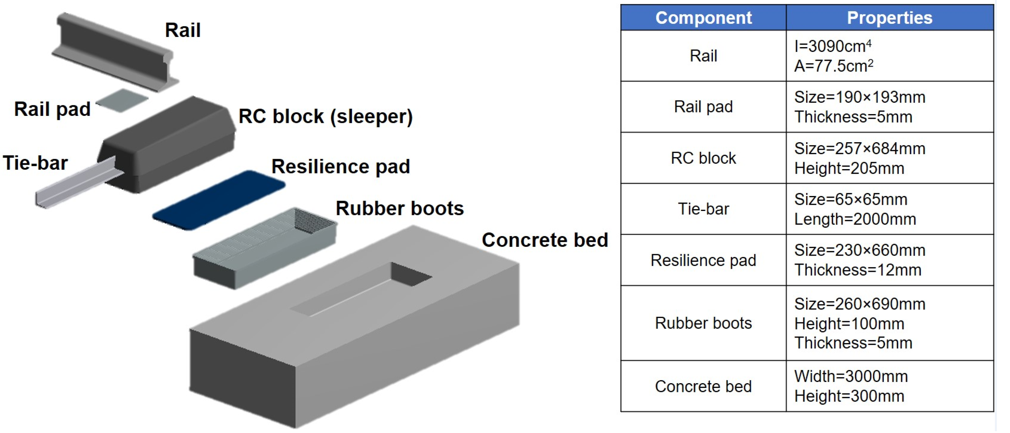
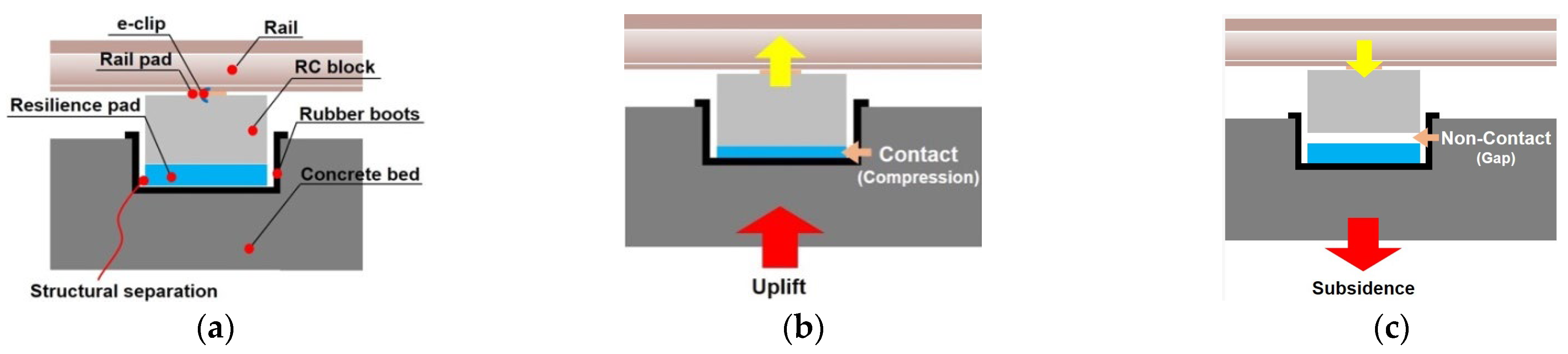
Figure 1 shows a block diagram of the STEDEF sleeper floating track system, the target structure of this study. The mechanism of interaction between this sleeper floating track system and the supporting substructure was analyzed in this study considering the structural characteristics of the track system. This interaction mechanism is illustrated in Figure 2, in which it can be observed that as the subway box tunnel deforms owing to uplift or subsidence, the concrete slab track constructed within is affected in different ways. In the target sleeper floating track system, the reinforced concrete (RC) sleeper (consisting of two RC blocks connected by a tie-bar) and concrete bed are separated by the resilience pad, as shown in Figure 2a. Thus, the deformation of the RC sleeper and rail is inconsistent with that of concrete bed. As a result, in the uplift condition, the resilience pad is compressed between the RC sleeper and concrete bed, as shown in Figure 2b; in the subsidence condition, the RC sleeper and the concrete bed are separated, creating a gap between them that constitutes a non-contact state, as shown in Figure 2c.
To quantitatively analyze the effects of substructure uplift and subsidence on the behavior of a sleeper floating track system inside an underground box tunnel, a three-dimensional (3D) finite element analysis of the sleeper floating track system–substructure interaction was performed in this study.
2. Materials and Methods
2.1. Field Measurement
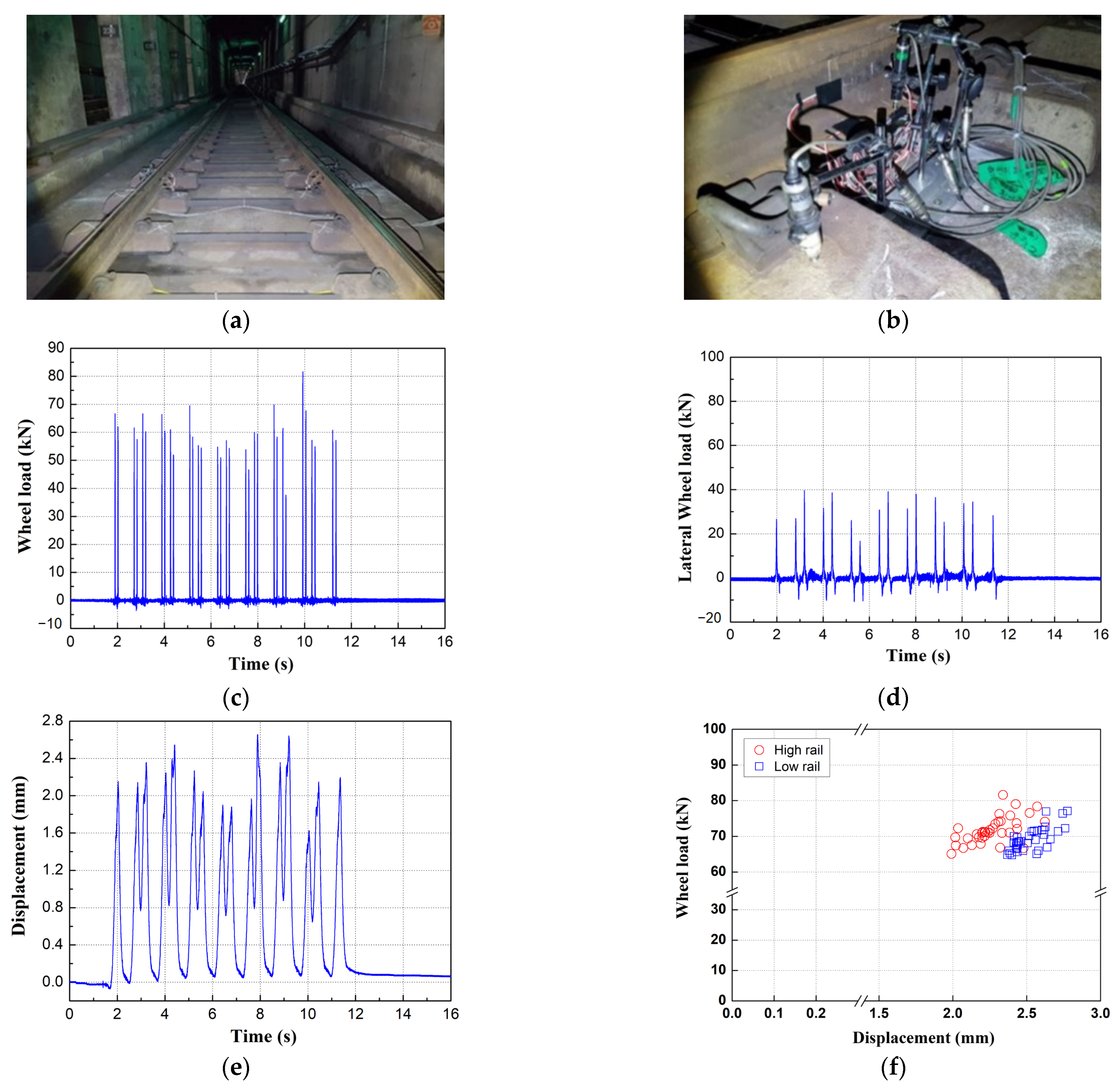
To evaluate the rail–girder interaction force generated at the end of the Yeongjong Bridge direct fixation track during train operation, the vertical displacements of the rail and RC sleeper were measured relative to the concrete bed at the center and at the end of the track segment using a linear variable differential transformer (LVDT) system, shown in Figure 3. The LVDTs (CDP-25M) employed in this study had a sensitivity of 500 × 10−6/mm, rated power of 6.25 mV/V ± 0.3%, and frequency response of 7 Hz. The displacements were measured and recorded automatically using a computer-controlled data acquisition system.
The maximum displacement in Figure 3e, which occurs when the wheel load is at the maximum in Figure 3c, was analyzed qualitatively and is shown in Figure 3f.
The field-measured dynamic wheel loads and displacements of the RC sleeper are shown in Figure 3f. The maximum dynamic and lateral wheel loads were approximately 80 kN and 40 kN, respectively, and the maximum vertical sleeper displacement was approximately 2.78 mm.
2.2. Finite Element Analysis
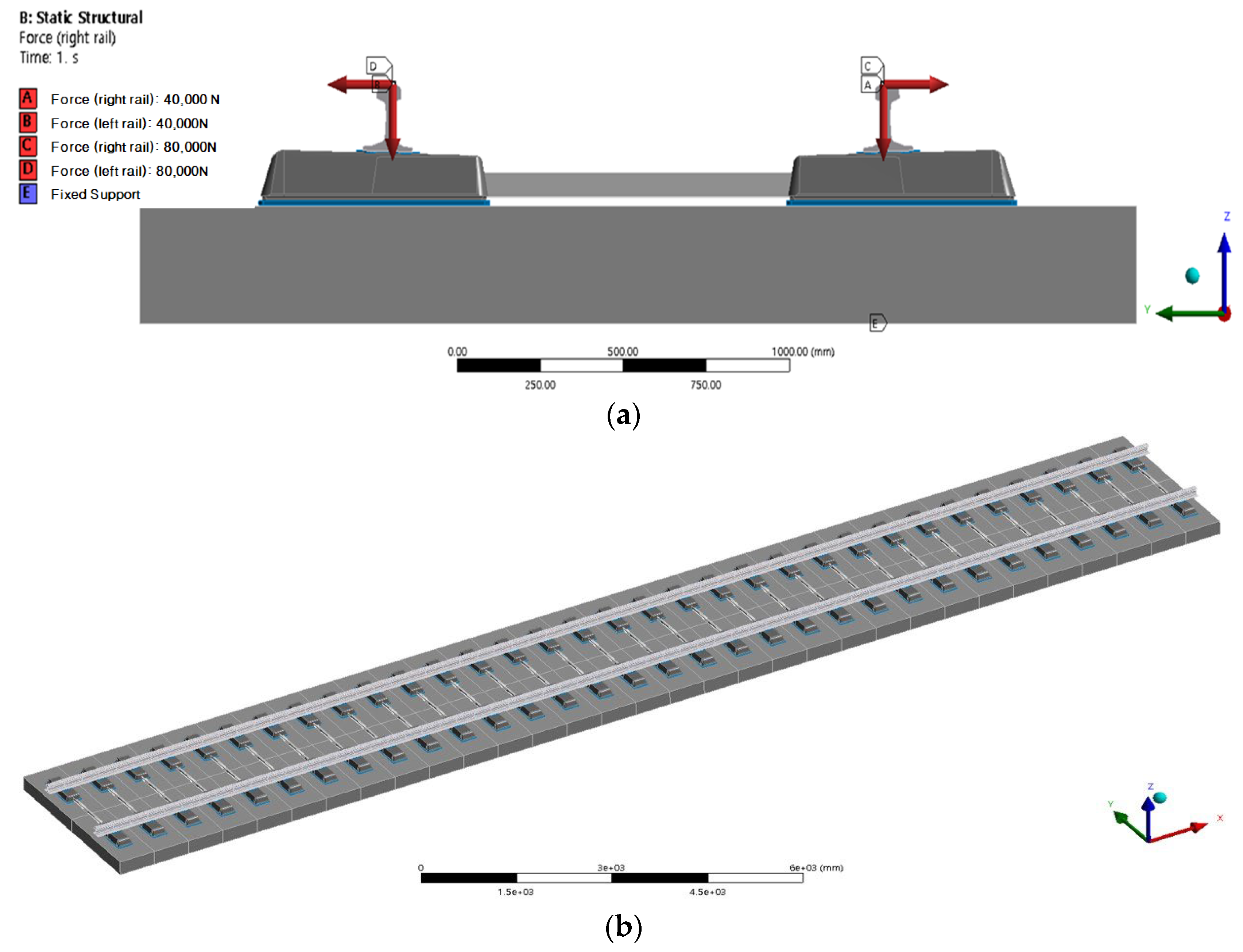
The ANSYS Ver 17.2 [16] software package was used to conduct the 3D finite element (FE) analysis in this study by employing solid elements. The lower part of the concrete bed was fixed under supported conditions; the vertical load was considered as the displacement condition (5–40 mm). The edges of both ends of the lower part of the concrete bed were fixed. Further, both ends of the lower rail edges were fixed. The boundary condition of the rail support was applied with a roller condition. The load conditions were applied in the vertical and horizontal rail directions. The mesh of the track model contained 888,564 nodes and 437,264 elements. The FE model of the booted sleeper track was configured using the parameters shown in Figure 4. The solid components of the STEDEF system evaluated in this study included the rail, rail pad, RC sleeper, resilience pad, rubber boots, tie-bar, and concrete bed. The mechanical properties of these components are listed in Table 1.
An FE analysis was first performed using the same conditions under which the field measurements were collected to verify the suitability of the model; then, various displacements were applied to the verified model to evaluate the resulting behavior of the sleeper track system. The load application and model boundary conditions used in the verification are illustrated in Figure 4a. For the boundary conditions of the full model, fixed support points were applied to both ends of the concrete bed and rail. The analysis domain for the rail was set to consider five rail support points beyond each end of the concrete bed. The full-scale model used to analyze the track deformation according to substructure uplift or subsidence is shown in Figure 4b. The length of the complete FE model was 20 m, and the rail was 20 m long for an analysis of rail deformation at the ends of the concrete bed.
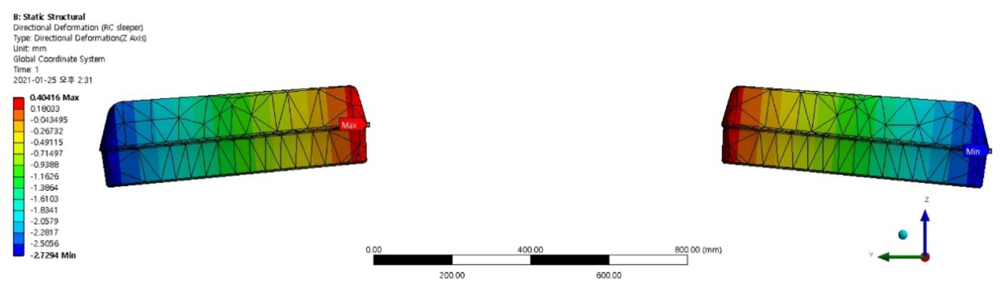
The dynamic and lateral wheel loads from the field measurements (i.e., 80 kN and 40 kN, respectively) were applied to the rails in the model shown in Figure 4a as the load conditions for verification of the FE model of the track system. The accuracy of the model was then confirmed by comparing the RC sleeper vertical displacement obtained from the field measurements with the RC sleeper displacement obtained from the FE analysis. Figure 5 shows the FE analysis results for the vertical displacement of the RC sleeper.
The RC sleeper vertical displacements obtained from the field measurement and FE analysis were approximately 2.78 mm (within a range of 2.05–3.86 mm) and 2.73 mm, respectively, as shown in Figure 5. Thus, the displacement obtained by the FE analysis was within approximately 1.8% of the field measurements. Therefore, the FE analysis model developed using the measured data (e.g., dynamic wheel load, lateral wheel load, and sleeper displacement) can be used to predict the deformation characteristics of the booted sleeper track system subjected to substructure deformation.
Differential settlement causes the structure to settle unevenly as the foundation ground of the structure settles down. Angular displacement of 1/500, which is the allowable condition for differential settlement and is a stable limit to prevent cracks in the structure, was applied. The maximum displacement applied to the verified FE model was set based on an allowable subsidence of 25 mm and a differential settlement of 40 mm (1/500). Additionally, the substructure deformation was considered to be equal to the deformation of the underground box structure, and this displacement was applied as the control condition of the track model. Thus, the subsidence or uplift at the center of the FE model was applied as ±5, ±10, ±20, ±30, or ±40 mm.
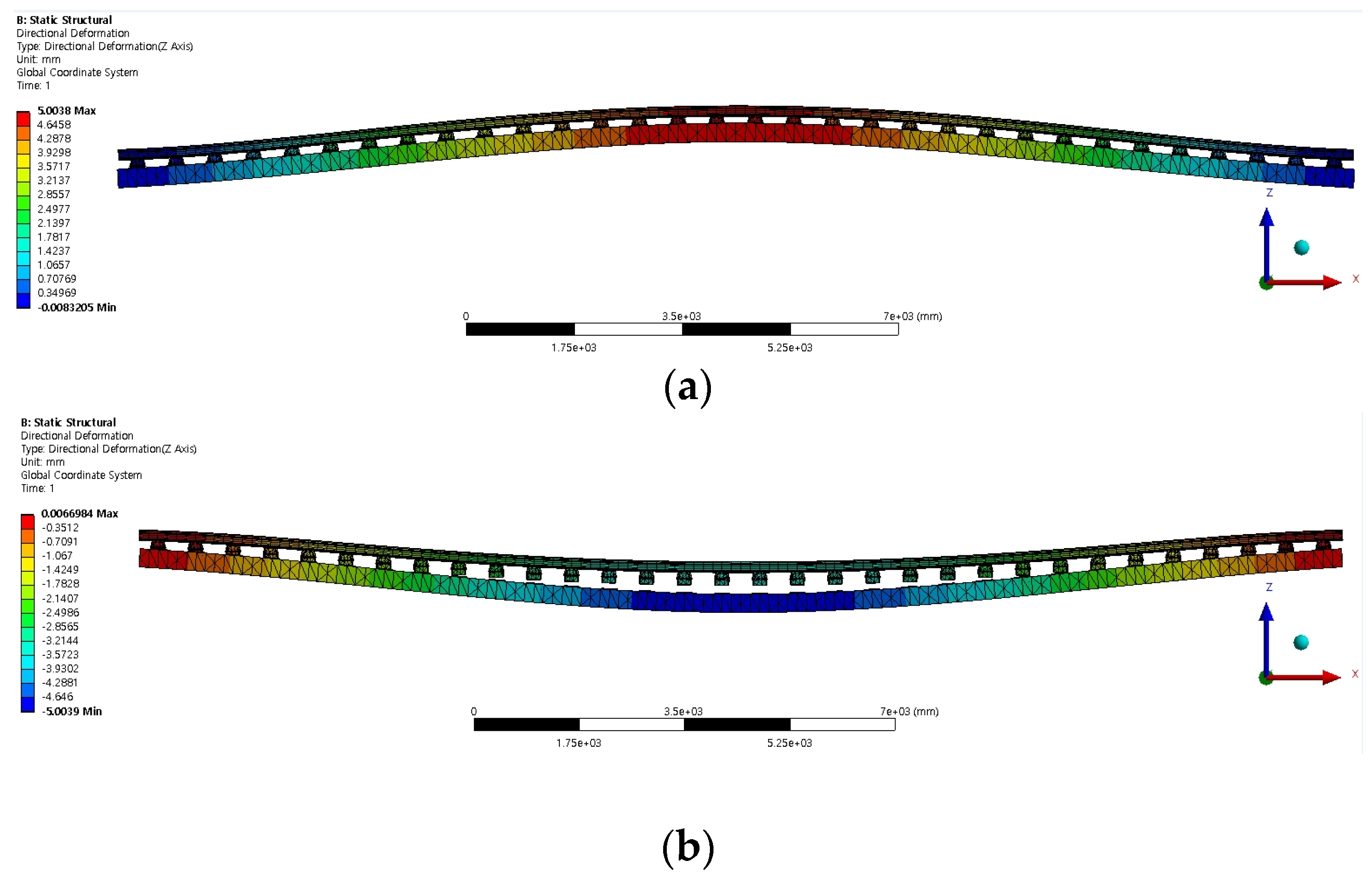
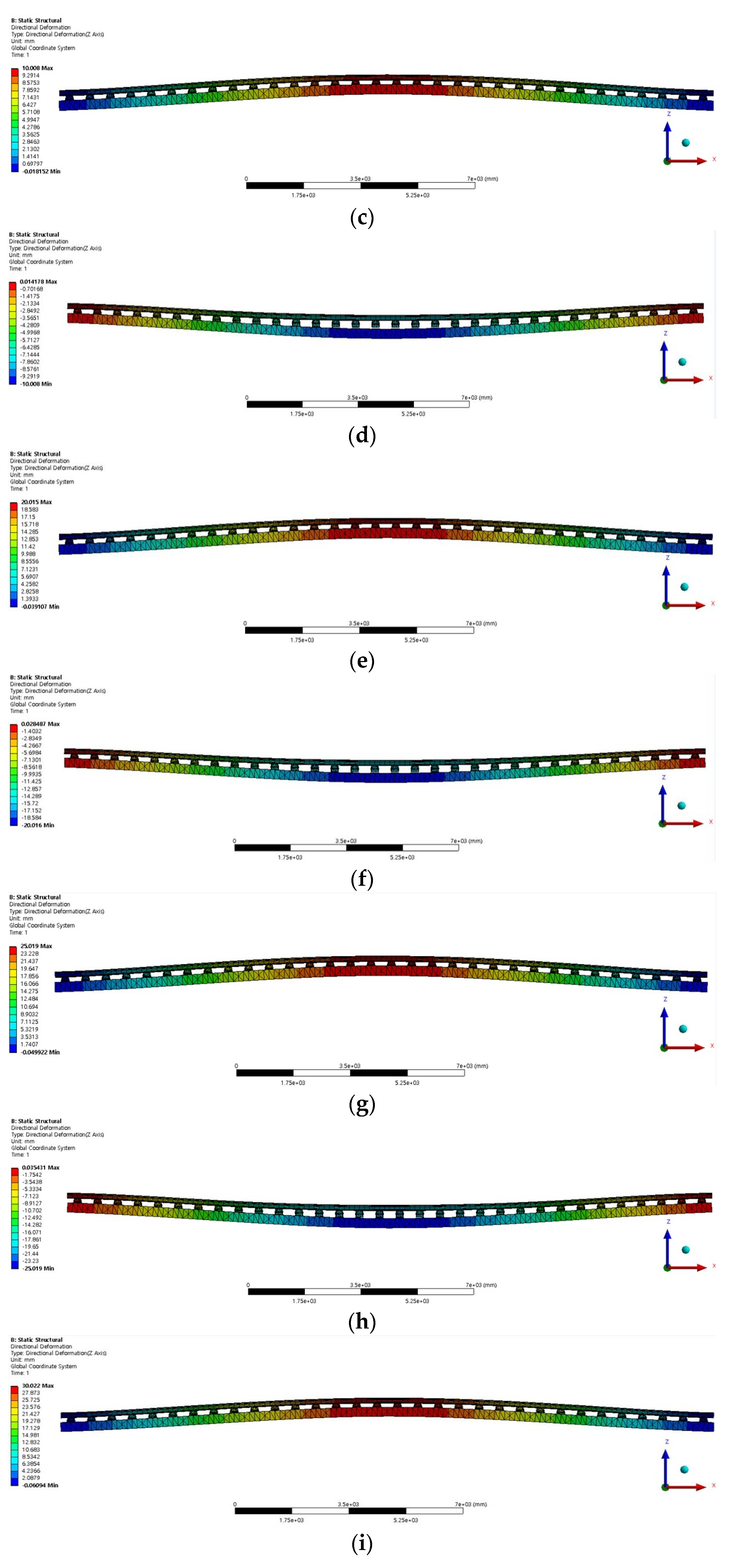
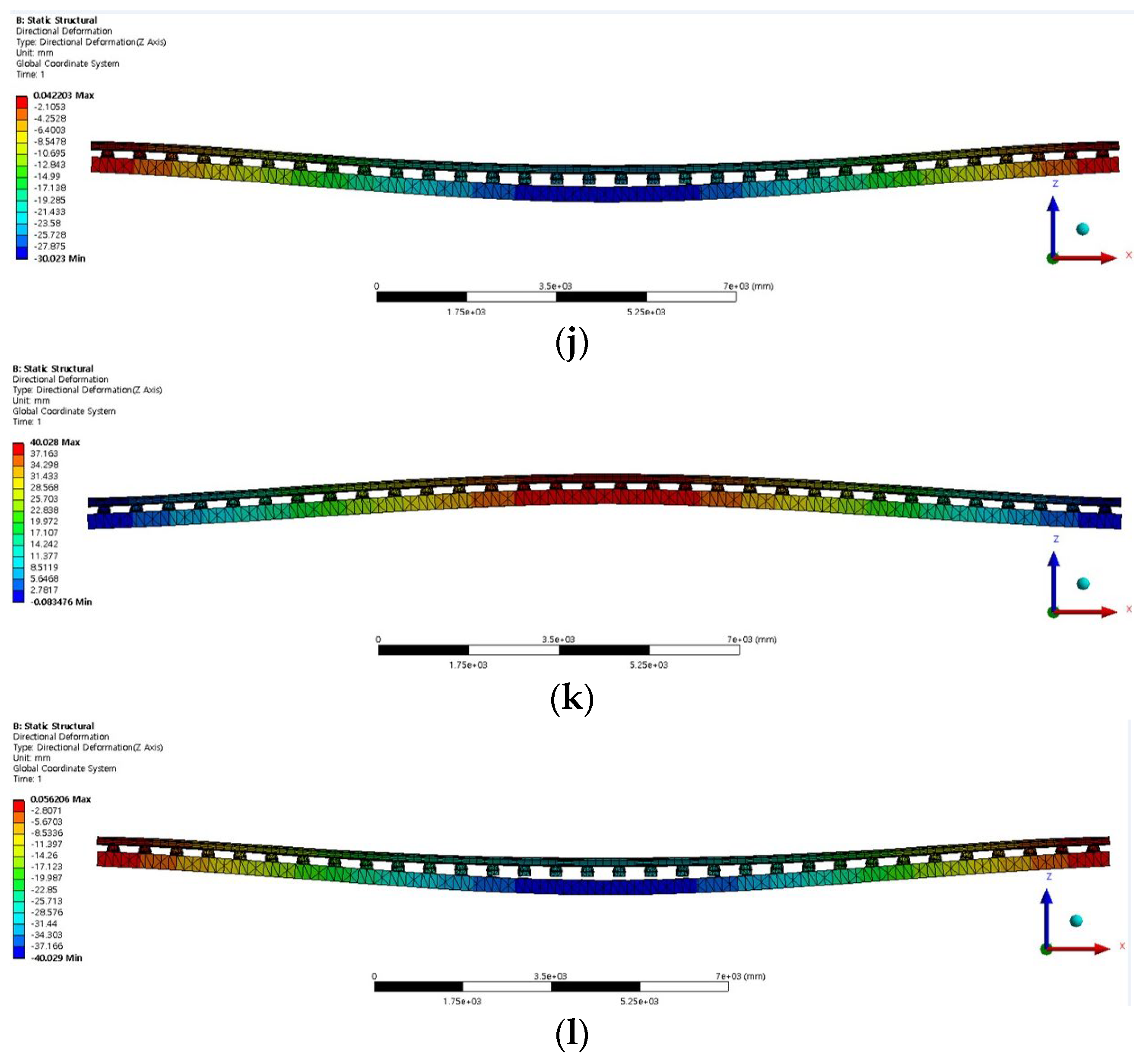
Figure 6a–l shows the general performance of this model, demonstrating the FE analysis results of uplift and subsidence of 5 mm, 10 mm, 20 mm, 25 mm, 30 mm, and 40 mm, respectively.
The results of the FE analysis under the 5 mm uplift and subsidence conditions indicate that the deformations of the concrete bed and the rail were similar under the uplift condition, as shown in Figure 6a. However, as shown in Figure 6b, a difference between the deformations of the concrete bed and the rail occurred under the subsidence condition, and—as expected—the rail deformation was found to be smaller than the concrete bed deformation. Thus, the developed FE model was considered to accurately reflect the behavior of the booted sleeper track system.
3. Results and Discussion
3.1. Relative Displacement between the Rail and Concrete Bed According to Substructure Deformation
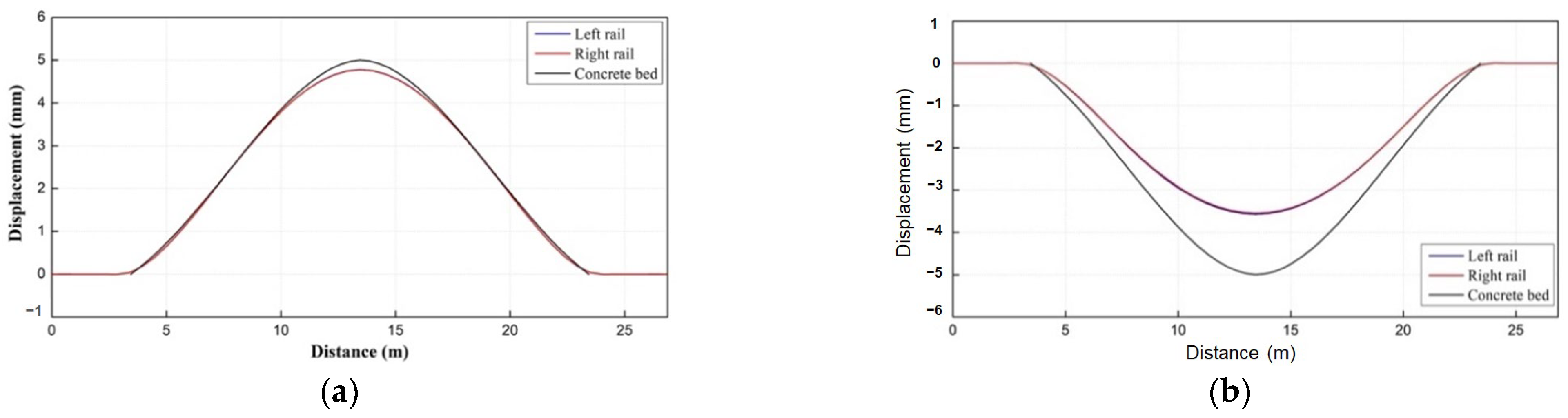
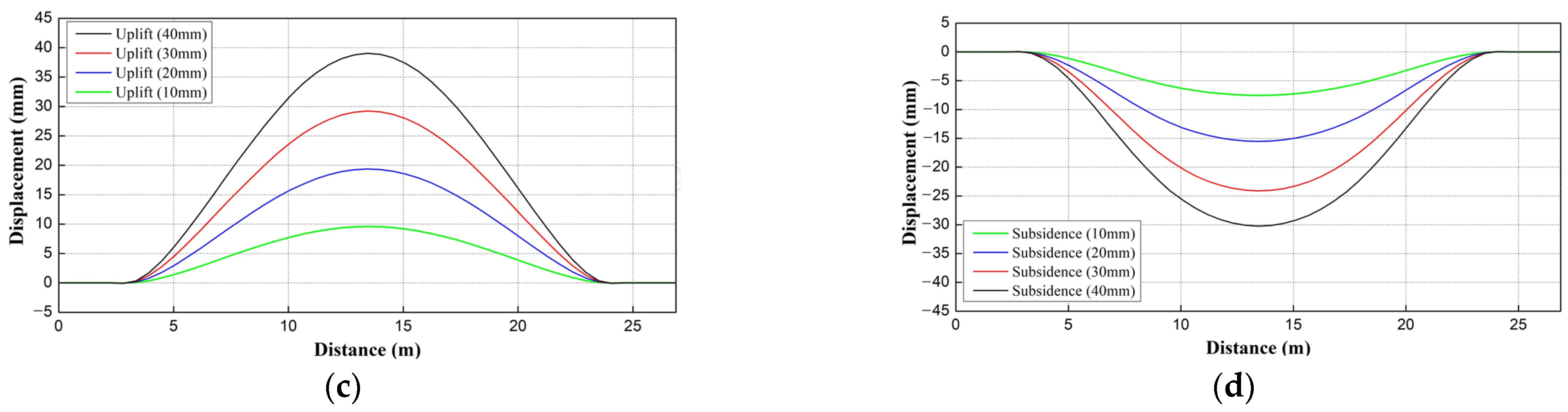
In this study, the relative displacement between the rail and concrete bed was analyzed according to the magnitude and direction of substructure deformation. Figure 7a,b shows the displacements of the two rails and the concrete bed under the 5 mm uplift and subsidence conditions, and Figure 7c,d shows the rail displacements under uplift and subsidence conditions, respectively, of 10, 20, 30, and 40 mm.
As shown in Figure 7a, for an uplift of 5 mm, the rail displacement was approximately 0.16 mm less than the displacement of the concrete bed. However, as shown in Figure 7b for 5 mm subsidence, the rail displacement was approximately 1.3 mm less than the displacement of the concrete bed. As evident from Figure 7c, the rail displacement was only slightly smaller (by 1 mm) than the applied substructure displacement for all uplift conditions. However, as shown in Figure 7d, the rail displacement was 30 mm for an applied substructure subsidence of 40 mm, indicating that a relative displacement of 10 mm occurred between the rail and bed.
Therefore, the compression of the resilience pad only slightly reduced the deformation of the rail due to the uplift of the concrete bed beneath, whereas the concrete sleeper and concrete bed were separated in the subsidence condition, causing the deformation of the rail to be notably smaller than that of the concrete bed.
3.2. Contact Conditions between the RC Sleepers and Concrete Bed According to Substructure Deformation
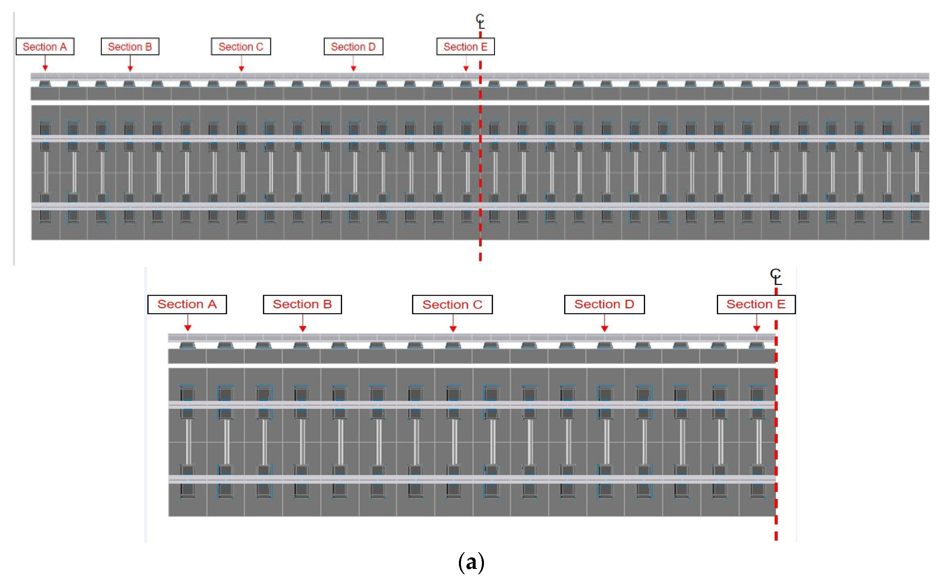
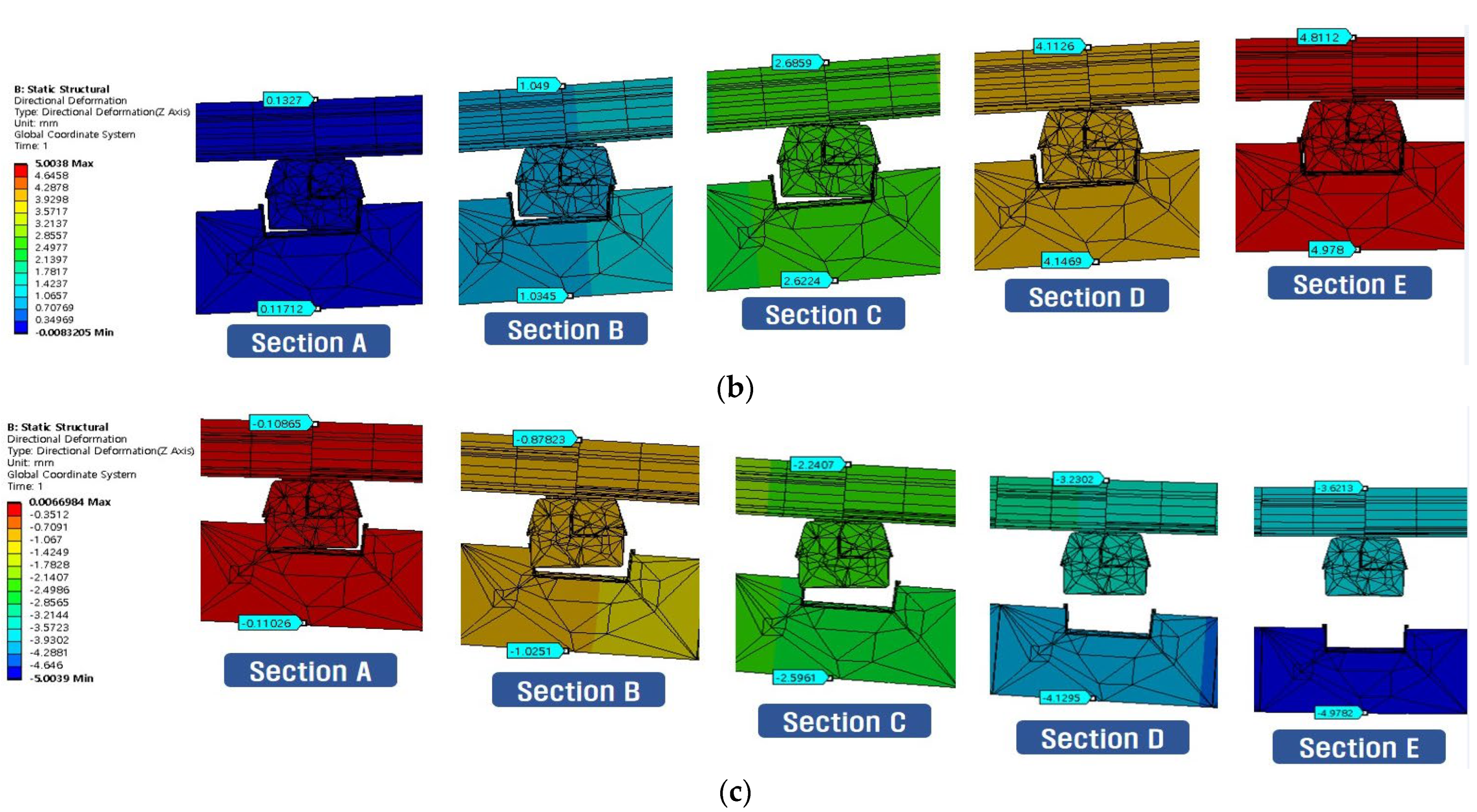
The contact conditions and relative displacements between the RC sleepers and concrete bed were analyzed by location according to the type of applied substructure deformation (i.e., uplift or subsidence). The analysis locations were selected with equal spacing from the end to the center of the model segment, labelled Section A to Section E in Figure 8a. Figure 8b,c shows the contact conditions obtained by the analysis at each location when the model was subjected to uplift or subsidence, respectively.
The analysis results of the contact conditions between the RC sleeper and concrete bed under substructure uplift, shown in Figure 8b, indicated that at Section E (i.e., the center of the concrete bed model), there was no rotation of the RC sleeper. On the other hand, the results indicated that the RC sleeper rotated toward the center of the concrete bed at Sections D through A. Similar to the analysis results under substructure uplift, the contact conditions between the RC sleeper and concrete bed under substructure subsidence also showed no rotation of the concrete sleeper at Section E (i.e., the concrete bed center), as can be observed in Figure 8c. However, the “floating sleeper” phenomenon, whereby the RC sleeper and concrete bed separated, clearly occurred at this location. In addition, the analysis results indicated that the RC sleepers rotated toward the center of the concrete bed model at Sections D through A. The consistency of the RC sleeper rotation phenomenon observed in the uplift and subsidence conditions indicated that this rotation was the result of the difference in the flexural curvature of the concrete bed and the rails.
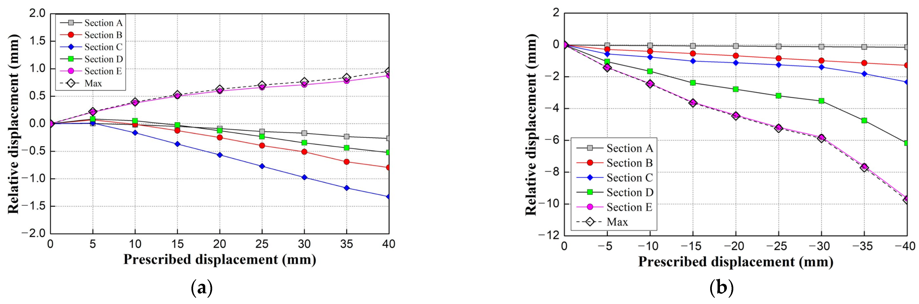
Additionally, the relative displacements between the concrete bed and RC sleepers were calculated at Sections A through E by subtracting the RC sleeper displacement from that of the concrete bed. In this analysis, a negative (−) relative displacement indicates the occurrence of a floating sleeper, and a positive (+) relative displacement indicates compressive deformation of the resilience pad. The relative displacement results are shown in Figure 9. As shown in Figure 9a, the maximum relative displacements under substructure uplift at Sections A, B, C, D, and E were 0.267, 0.796, 1.325, 0.524, and 0.875 mm, respectively. Additionally, note that the floating sleeper phenomenon occurred at all locations from Sections A to D for the evaluated uplift conditions between 10 and 40 mm. On the other hand, at Section E (i.e., at the center of the concrete bed), the resilience pad clearly experienced elastic deformation due to compression, reducing the uplift displacement. As shown in Figure 9b, the maximum relative displacements under substructure subsidence at Sections A, B, C, D, and E were 0.146, 1.283, 2.333, 6.181, and 9.648 mm, respectively, with the floating sleeper phenomenon occurring at all locations. Therefore, the results of the relative displacement analysis indicated that the difference in the flexural curvature of the concrete bed and rail affected the track deformation according to the displacement direction.
3.3. Possibility of Tension Cracking in the Concrete Bed Due to Substructure Deformation
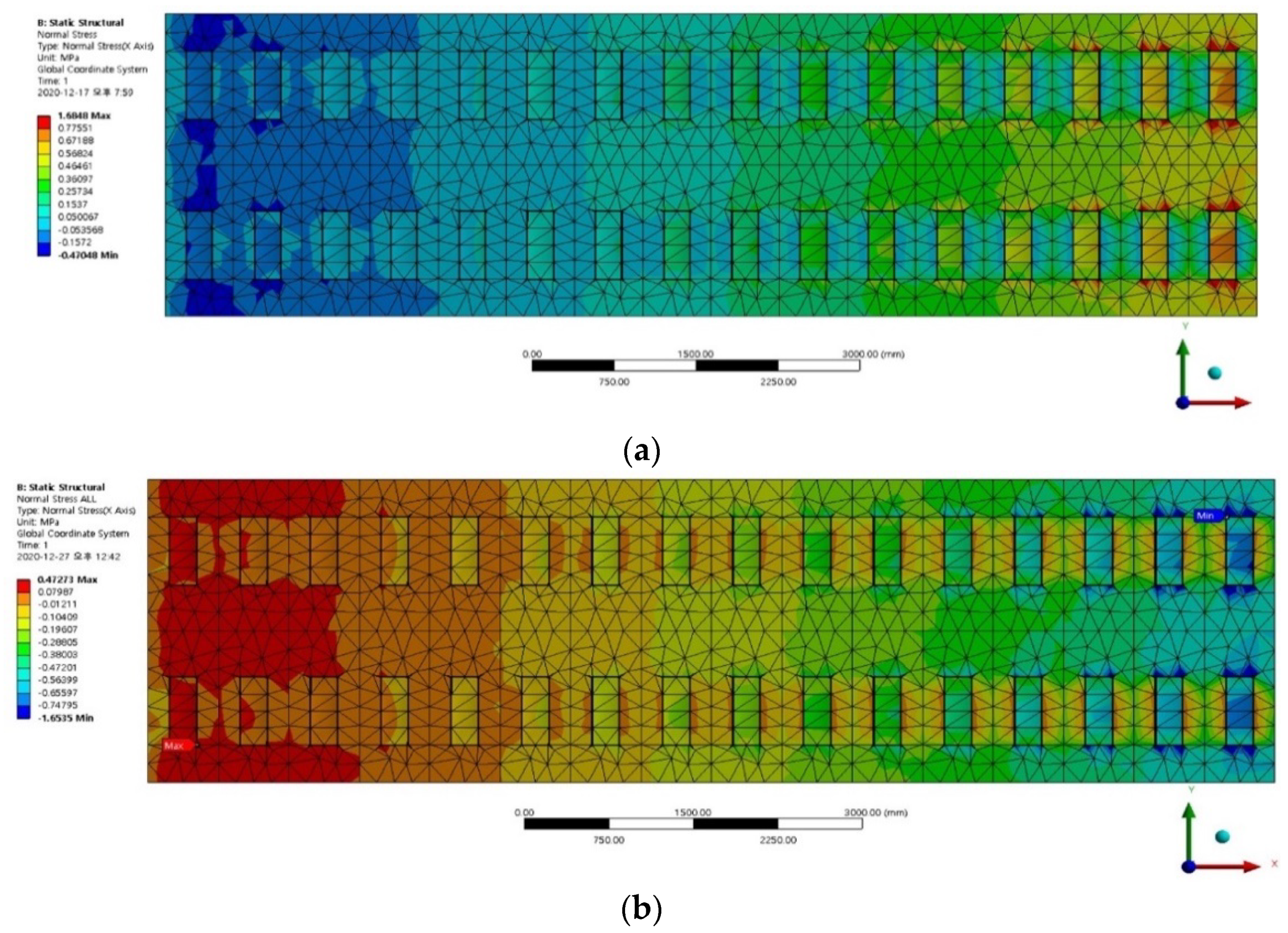
In this section, the possibility of tension cracking in the concrete bed due to substructure deformation (i.e., uplift or subsidence) is analyzed by comparing the analysis results with the standard value of concrete flexural strength (i.e., modulus of rupture). Here (where fck is the standard design compressive strength of concrete), which was calculated according to the 2012 Standard Specifications for Concrete Structures [15,19]. Figure 10 shows the normal stress induced on the top surface of the concrete bed in the longitudinal (x) direction by substructure deformation.
When subjected to 5 mm of substructure uplift, as shown in Figure 10a, at the center of the concrete bed, compressive stress occurred along the rails between the RC sleepers, while tensile stress occurred along the inner and outer faces of the RC blocks. However, at the end of the concrete bed, the inner and outer faces of the RC blocks exhibited greater compressive stresses than did the locations along the rails between the RC sleepers.
When subjected to 5 mm of substructure subsidence, as shown in Figure 10b, at the center of the concrete bed, tensile stress occurred along the rails between the RC sleepers, while compressive stress occurred along the inner and outer faces of the RC blocks. However, at the end of the concrete bed, the inner and outer faces of the RC blocks were under greater tensile stress than the locations along the rails between the RC sleepers.
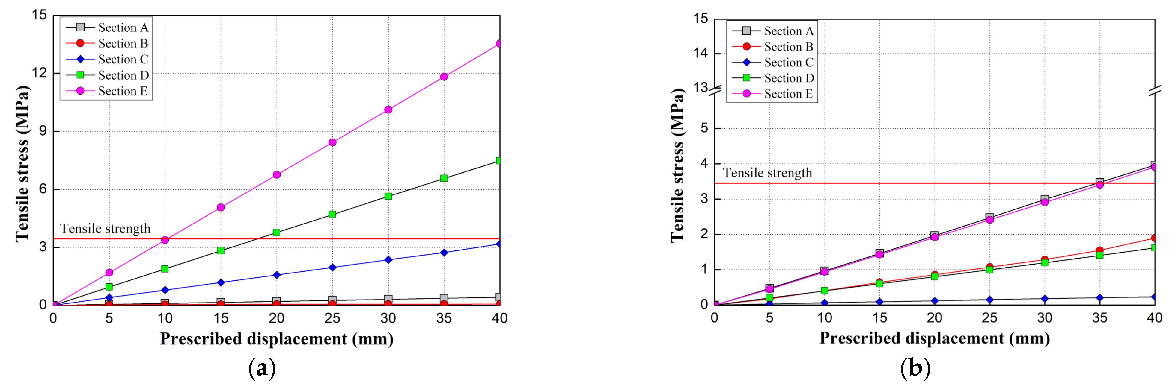
The results of the concrete bed tensile stress analyses shown in Figure 10 indicated that the locations of the tensile and compressive stresses in the uplift condition were the same as the locations of the compressive and tensile stresses, respectively, in the subsidence condition. The tensile stress results are reported according to substructure displacement conditions in Figure 11 for each location defined in Figure 8a.
As can be observed in the tensile stresses reported in Figure 11a, the maximum tensile stress at Section E (i.e., the center of the concrete bed model) exceeded the flexural strength of the concrete bed under uplifts of 10 mm or greater. At Section D, the maximum tensile stress exceeded the flexural strength of the concrete bed under uplifts of 20 mm or greater. On the other hand, at Sections A–C, the maximum tensile stress never exceeded the flexural strength of the concrete bed, even under an uplift of 40 mm; however, at Section C, the maximum tensile stress may exceed the flexural strength under an uplift greater than 40 mm.
As shown in Figure 11b, the maximum tensile stress exceeded the flexural strength of the concrete at Sections E and A under subsidences of 35 mm or greater. At Sections B, C, and D, the tensile stress did not exceed the flexural strength of the concrete bed under subsidences up to and likely exceeding 40 mm. Furthermore, the smallest tensile stress occurred at Section C, which was located between the center and the end of the concrete bed.
Furthermore, Figure 11b indicates that the tensile stresses at Sections A (end) and E (center) were similar under the substructure subsidence condition. At Section E, this tensile stress occurred at the point of maximum subsidence, and it is considered to be caused by the resulting flexural deformation at this location. At Section A, however, it is proposed that RC sleeper rotation caused compressive stress beneath the sleepers, which induced the observed tensile stress between the sleepers. Under the substructure uplift condition shown in Figure 11a, the tensile stress was found to be the largest at only Section E (center), the point of maximum uplift, and was the result of upward flexural deformation. At Section A, the tensile stress was determined to be caused by the rotation of the RC sleeper, though it was smaller than that observed under the subsidence condition.
The results of the tensile stress analyses indicated that substructure uplift was more likely to induce tension cracking in the concrete bed than substructure subsidence. In the substructure uplift condition, the maximum tensile stress occurred in the concrete bed on the inner and outer faces of the RC blocks at the point of maximum uplift, and tension cracks could therefore occur within approximately 5 m on each side of this point. In the substructure subsidence condition, tension cracks may occur in the concrete bed along the rails between the RC sleepers at the point of maximum subsidence, though a relatively high tensile stress also occurred on the inner and outer faces of the RC blocks at the end of the track segment, where the subsidence was nearly zero.
3.4. Possibility of Shear Failure of the Concrete Bed Due to Sleeper Rotation
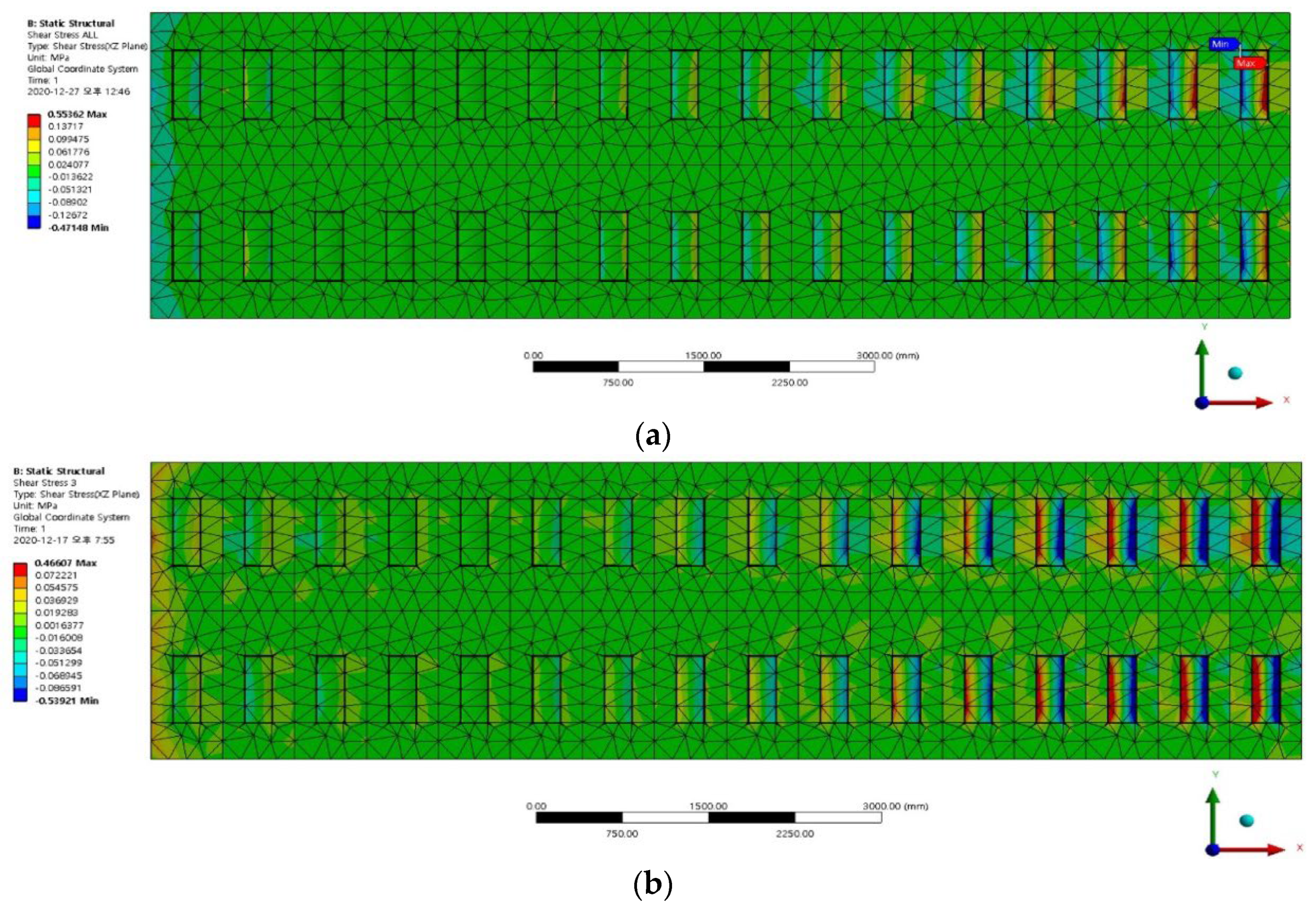
In this section, the possibility that shear failure of the concrete bed could occur due to the observed sleeper rotation induced by substructure deformation was investigated. To analyze the likelihood of concrete bed shear cracks, the standard concrete shear strength, [15], was compared with the shear stress analysis results shown in Figure 12 according to the substructure deformation direction.
As shown in Figure 12, the concrete bed shear stress due to substructure uplift was similar to that due to subsidence: the maximum shear stress was observed at Section E, which was the point of maximum displacement in either case, and it decreased toward Section A. However, because the RC sleepers rotated in opposite directions according to the substructure uplift or subsidence conditions, the shear stress was also in opposite directions.
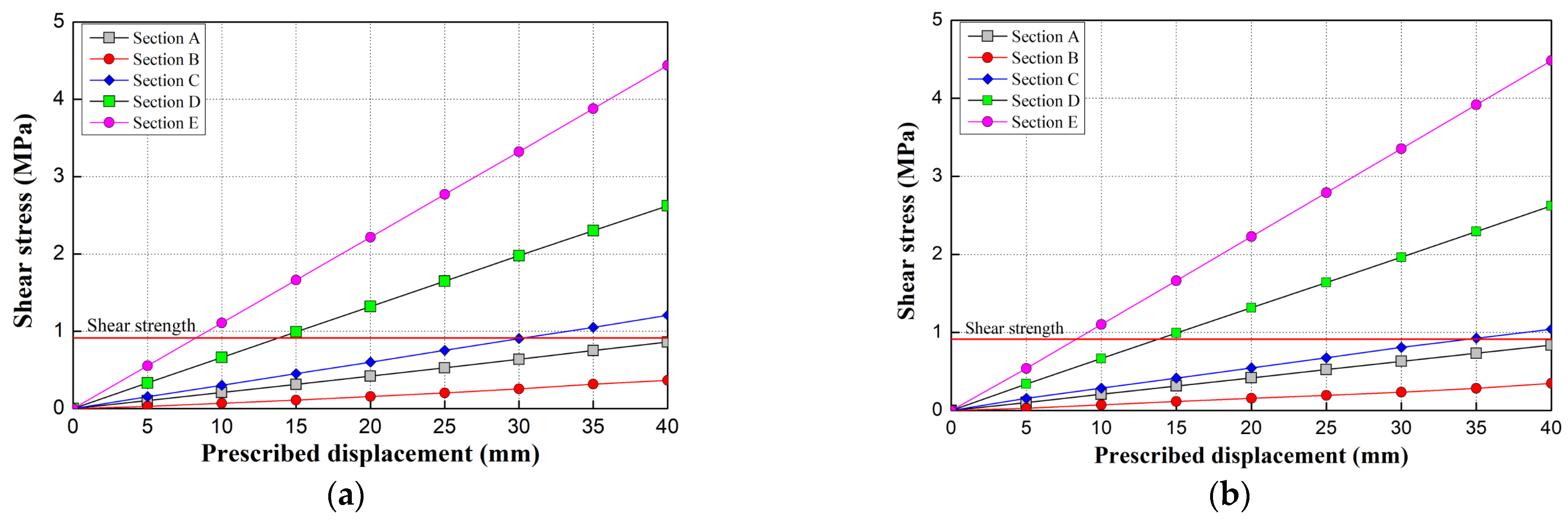
The shear stress at each location, defined in Figure 8a, according to the magnitude of substructure deformation was then compared to the calculated concrete bed shear strength to evaluate the possibility of shear failure, as shown in Figure 13.
At Section D, the maximum shear stress exceeded the shear strength of the concrete bed at an uplift or subsidence of 15 mm or greater. At Section C, the maximum shear stress exceeded the shear strength of the concrete bed at an uplift greater than 30 mm or a subsidence of 35 mm or greater. The shear stress at Section B was smaller than that at Section A, and it did not exceed the shear strength at either location up to an uplift or subsidence of 40 mm, though the shear stress at Section A would likely exceed the shear strength at displacements greater than 40 mm.
As shown in Figure 13, under either substructure uplift or subsidence, the likelihood of shear failure due to flexure was high at Sections E and D, which were close to the point of maximum displacement, and decreased with increasing distance toward the ends of the model. However, for both substructure uplift and subsidence, the shear stress at Section A, which was at the end of the concrete bed, was greater than that at Section B. Therefore, it was determined that the shear stress in the concrete bed was caused by flexural deformation at Sections E to C, whereas although the magnitude of the shear stress at Section A was similar to that at Section C, it is inferred that the shear stress at Section A was caused by the rotation of the RC sleeper.
The results of this examination of the possibility of concrete bed shear failure due to substructure deformation indicated that the locations of maximum shear stress were similar for both substructure uplift and subsidence. At locations within 5 m each side of the point of maximum displacement, the shear stress in the concrete bed was observed to increase due to flexure, and shear stress due to the rotation of the concrete sleepers was observed near the ends of the concrete bed, indicating that shear cracks may occur in these locations. Therefore, it is suggested that a suitable range for the investigation of concrete bed cracking for tunnel sections with substructure deformation should be based on the locations of the maximum uplift and subsidence points, as well as the ends of the deformed track sections.
4. Conclusions
In this study, the effect of substructure deformation on the behavior of a sleeper floating track system installed in a subway box tunnel structure was analyzed using a 3D FE model. The mechanism of the sleeper floating track system–substructure interaction due to substructure deformation was investigated, and the possibility of concrete bed cracking was explored. The main findings of this study can be summarized as follows.
- An analysis of the interaction mechanism between the sleeper floating track system and its substructure under uplift indicated that the resilience pad between the RC sleeper and concrete bed was compressed, potentially resulting in a decrease in the elastic displacement of the track under load. This would lead to an increase in the track support stiffness, thereby increasing the track bearing capacity. In contrast, under substructure subsidence, the occurrence of the “floating sleeper” phenomenon could affect the rail fastener bearing capacity. Therefore, to counter the effects of the floating sleeper phenomenon, the spacing between sleepers should be increased in order to increase the flexural stress in the rail and thus relax the stress in the rail fasteners.
- An analysis of the relative displacement and contact conditions between the rail and the concrete bed according to substructure deformation indicated that the rail and concrete bed deformations were similar under substructure uplift, with the rail deformation being only slightly smaller owing to the compression of the resilience pad at the point of maximum displacement, which caused minor instances of the floating rail phenomenon elsewhere. On the other hand, under substructure subsidence, the rail deformation was noticeably smaller than that of the concrete bed, and the floating sleeper phenomenon occurred extensively.
- An examination of the tensile stress in the concrete bed due to substructure deformation determined that concrete bed tension cracking may occur at points of maximum uplift and subsidence. Under substructure uplift, it was found that tension cracking could occur within approximately 5 m each side of the point of maximum uplift, on the inner and outer faces of the RC blocks; under substructure subsidence, it was determined that tension cracking could occur within approximately 2.5 m on each side of the point of maximum subsidence, along the rail between the RC sleepers. Thus, substructure uplift was determined to be more likely to cause tension cracking than substructure subsidence. However, because the tensile stresses were observed to be similar at the point of maximum subsidence and at the end of the concrete bed, further analysis of the tension cracking at the end locations remains necessary.
- An examination of the possibility that RC sleeper rotation due to substructure deformation could cause the shear failure of the concrete bed revealed that the concrete sleepers rotated in opposite directions relative to the point of maximum uplift or subsidence. Concrete shear cracks were likely to occur within 5 m either side of the points of maximum uplift and subsidence. Under either substructure uplift or subsidence, the RC sleepers at the end of the concrete bed were observed to rotate, potentially inducing shear failure owing to contact. Therefore, it is necessary to perform further investigation of shear cracking at the ends of the concrete bed in addition to the points of maximum uplift or subsidence.
In future studies, it will also be necessary to analyze the effects of substructure deformation on the dynamic behavior characteristics of floating track systems, such as the natural track frequency, track impact factor, rail fastener bearing capacity, and train stability during travel.
Author Contributions
Conceptualization, J.-Y.C. and S.-H.K.; methodology, J.-Y.C.; formal analysis, D.-H.A. and S.-H.K.; investigation, D.-H.A. and J.-Y.C.; writing—original draft preparation, J.-Y.C.; D.-H.A. and S.-H.K.; writing—review and editing, S.-H.K. All authors have read and agreed to the published version of the manuscript.
Funding
This research received no external funding.
Institutional Review Board Statement
Not applicable.
Informed Consent Statement
Not applicable.
Data Availability Statement
Data sharing is no applicable to this article.
Conflicts of Interest
The authors declare no conflict of interest.
References
- Berggren, E.G.; Kaynia, A.M.; Dehlbom, B. Identification of substructure properties of railway tracks by dynamic stiffness measurements and simulations. J. Sound Vib. 2010, 329, 3999–4016. [Google Scholar] [CrossRef]
- With, C.; Bordare, A. Evaluation of track stiffness with a vibrator for prediction of train-induced displacement on railway embankment. Soil Dyn. Earthq. Eng. 2009, 29, 1187–1197. [Google Scholar] [CrossRef]
- Knothe, K.; Grassie, S.L. Modelling of railway track and vehicle/track interaction at high frequencies. Veh. Syst. Dyn. 1993, 22, 209–262. [Google Scholar] [CrossRef]
- Liang, B.; Zhu, D.; Cai, Y. Dynamic analysis of the vehicle–subgrade model of a vertical coupled system. J. Sound Vib. 2001, 245, 79–92. [Google Scholar] [CrossRef]
- Sheng, X.; Jones, C.; Petyt, M. Ground vibration generated by a load moving along a railway track. J. Sound Vib. 1999, 228, 129–156. [Google Scholar] [CrossRef]
- Costa, P.A.; Calçada, R.; Cardoso, A.S.; Bodare, A. Influence of soil non-linearity on the dynamic response of high-speed railway tracks. Soil Dyn. Earthq. Eng. 2010, 30, 221–235. [Google Scholar] [CrossRef]
- Esveld, C. Modern Railway Track, 2nd ed.; MRT-Productions: Zaltbommel, The Netherlands, 2001. [Google Scholar]
- Dahlberg, T. Solid Mechanics/IKP, Railway Track Dynamics—A Survey; Linköping University: Linköping, Sweden, 2003; unpublished. [Google Scholar]
- Ebersohn, W.; Trevizo, M.C.; Selig, E.T. Effect of low track modulus on track performance. In Proceedings of the International Heavy Haul Association, 5th International Heavy Haul Conference, Beijing, China, 6–13 June 1993; pp. 379–388. [Google Scholar]
- Plenge, M.; Lammering, R. The dynamics of railway track and subgrade with respect to deteriorated sleeper support. In System Dynamics and Long-Term Behaviour of Railway Vehicles, Track and Subgrade; Springer: Berlin/Heidelberg, Germany, 2003; pp. 295–314. [Google Scholar]
- Choi, J.-Y.; Kim, S.-H.; Lee, K.-Y.; Chung, J.-S. Dynamic behavior of track bridge on serviced long-span road/railway bridge. Appl. Sci. 2019, 10, 148. [Google Scholar] [CrossRef] [Green Version]
- Choi, J.-Y.; Chung, J.-S.; Kim, S.-H. Experimental study on track-bridge interactions for direct fixation track on long-span railway bridge. Shock. Vib. 2019, 2019, 1903752. [Google Scholar] [CrossRef] [Green Version]
- Choi, J.-Y.; Kim, S.-H. Impact evaluation of track girder bearing on Yeongjong Grand Bridge. Appl. Sci. 2019, 10, 68. [Google Scholar] [CrossRef] [Green Version]
- Choi, J.-Y.; Kim, S.-H. Qualitative prediction model for dynamic behavior of ballasted tracks. Appl. Sci. 2020, 10, 6258. [Google Scholar] [CrossRef]
- Wang, H.; Silvast, M.; Markine, V.; Wiljanen, B. Analysis of the dynamic wheel loads in railway transition zones considering the moisture condition of the ballast and subballast. Appl. Sci. 2017, 7, 1208. [Google Scholar] [CrossRef] [Green Version]
- Hu, P.; Zhang, C.; Guo, W.; Wang, Y. Dynamic response of a bridge-embankment transition with emphasis on the coupled train-track-subgrade system. Appl. Sci. 2020, 10, 5982. [Google Scholar] [CrossRef]
- Jia, P.-J.; Zhao, W.; Chen, Y.; Li, S.-G.; Han, J.-Y.; Dong, J.-C. A case study on the application of the steel tube slab structure in construction of a subway station. Appl. Sci. 2018, 8, 1437. [Google Scholar] [CrossRef] [Green Version]
- Ansys Inc. ANSYS® 2007 ANSYS Workbench 17.2; ANSYS Inc.: Cannonsberg, PA, USA, 2016. [Google Scholar]
- Korean Concrete Institute. Korean Design Standard; Korean Concrete Institute: Seoul, Korea, 2012. [Google Scholar]
Figure 1.
Schematic of the booted sleeper track system (STEDEF).

Figure 2.
Interaction between the booted sleeper track (STEDEF) and substructure under the (a) general condition; (b) uplift condition; and (c) subsidence condition.
Figure 2.
Interaction between the booted sleeper track (STEDEF) and substructure under the (a) general condition; (b) uplift condition; and (c) subsidence condition.

Figure 3.
Field test setup and examples of collected data: (a) view of the test area; (b) measurement setup; (c) example of the measured dynamic wheel load; (d) example of the measured lateral wheel load; (e) example of the measured RC sleeper vertical displacement; (f) distribution of wheel load and RC sleeper displacement measurements.

Figure 4.
FE model of the booted sleeper track system: (a) load and boundary conditions for model verification; (b) full model for substructure displacement analysis.
Figure 4.
FE model of the booted sleeper track system: (a) load and boundary conditions for model verification; (b) full model for substructure displacement analysis.

Figure 5.
FE analysis results for the vertical displacement of the RC sleeper.

Figure 6.
FE analysis results (displacement, z direction) for: (a) 5 mm uplift; (b) 5 mm subsidence; (c) 10 mm uplift; (d) 10 mm subsidence; (e) 20 mm uplift; (f) 20 mm subsidence; (g) 25 mm uplift; (h) 25 mm subsidence; (i) 30 mm uplift; (j) 30 mm subsidence; (k) 40 mm uplift; and (l) 40 mm subsidence.


Figure 7.
FE analysis results (displacement, z direction) for: (a) rails and concrete bed under 5 mm uplift; (b) rails and concrete bed under 5 mm subsidence; (c) rails under 10–40 mm uplift; and (d) rails under 10–40 mm subsidence.
Figure 7.
FE analysis results (displacement, z direction) for: (a) rails and concrete bed under 5 mm uplift; (b) rails and concrete bed under 5 mm subsidence; (c) rails under 10–40 mm uplift; and (d) rails under 10–40 mm subsidence.


Figure 8.
FE analysis results (displacement, z direction), according to location shown in (a), for (b) 5 mm uplift or (c) 5 mm subsidence.
Figure 8.
FE analysis results (displacement, z direction), according to location shown in (a), for (b) 5 mm uplift or (c) 5 mm subsidence.


Figure 9.
FE analysis results (relative displacement between rail and bed, z direction) according to magnitude of (a) uplift or (b) subsidence.
Figure 9.
FE analysis results (relative displacement between rail and bed, z direction) according to magnitude of (a) uplift or (b) subsidence.

Figure 10.
FE analysis results (normal stress on the top surface of the concrete bed, x direction) for (a) 5 mm uplift or (b) 5 mm subsidence (positive is tension).
Figure 10.
FE analysis results (normal stress on the top surface of the concrete bed, x direction) for (a) 5 mm uplift or (b) 5 mm subsidence (positive is tension).

Figure 11.
FE analysis results (tensile stress, x direction) according to magnitude of (a) uplift or (b) subsidence.
Figure 11.
FE analysis results (tensile stress, x direction) according to magnitude of (a) uplift or (b) subsidence.

Figure 12.
FE analysis results (shear stress, xz direction) for (a) 5 mm uplift and (b) 5 mm subsidence.
Figure 12.
FE analysis results (shear stress, xz direction) for (a) 5 mm uplift and (b) 5 mm subsidence.

Figure 13.
FE analysis results (shear stress, xz direction) according to magnitude of (a) uplift or (b) subsidence.
Figure 13.
FE analysis results (shear stress, xz direction) according to magnitude of (a) uplift or (b) subsidence.


Table 1.
Material properties of booted sleeper track (STEDEF) system components.
| Components | Properties | ||
|---|---|---|---|
| Elastic Modulus (MPa) | Density (kN/m3) | Poisson’s Ratio (υ) | |
| Rail | 210,000 | 77.01 | 0.3 |
| Rail pad | 71.4 | 9.32 | 0.2 |
| RC block | 26,086 | 22.56 | 0.18 |
| Resilience pad | 0.9778 | 6.87 | 0.49 |
| Rubber boots | 21.6 | 7.85 | 0.2 |
| Concrete bed | 26,086 | 22.56 | 0.18 |
| Tie-bar | 200,000 | 77.01 | 0.3 |
Publisher’s Note: MDPI stays neutral with regard to jurisdictional claims in published maps and institutional affiliations. |
© 2021 by the authors. Licensee MDPI, Basel, Switzerland. This article is an open access article distributed under the terms and conditions of the Creative Commons Attribution (CC BY) license (https://creativecommons.org/licenses/by/4.0/).
Share and Cite
MDPI and ACS Style
Choi, J.-Y.; Ahn, D.-H.; Kim, S.-H. Behavior Characteristics of a Booted Sleeper Track System According to Substructure Deformation. Appl. Sci. 2021, 11, 4507. https://0-doi-org.brum.beds.ac.uk/10.3390/app11104507
AMA Style
Choi J-Y, Ahn D-H, Kim S-H. Behavior Characteristics of a Booted Sleeper Track System According to Substructure Deformation. Applied Sciences. 2021; 11(10):4507. https://0-doi-org.brum.beds.ac.uk/10.3390/app11104507
Chicago/Turabian StyleChoi, Jung-Youl, Dae-Hui Ahn, and Sun-Hee Kim. 2021. "Behavior Characteristics of a Booted Sleeper Track System According to Substructure Deformation" Applied Sciences 11, no. 10: 4507. https://0-doi-org.brum.beds.ac.uk/10.3390/app11104507
Note that from the first issue of 2016, this journal uses article numbers instead of page numbers. See further details here.