
Conversion of a Network Section with Loads, Storage Systems and Renewable Generation Sources into a Smart Microgrid

 , , ,
, , ,  , and
, and 
Abstract
:1. Introduction
2. Revision of Literature
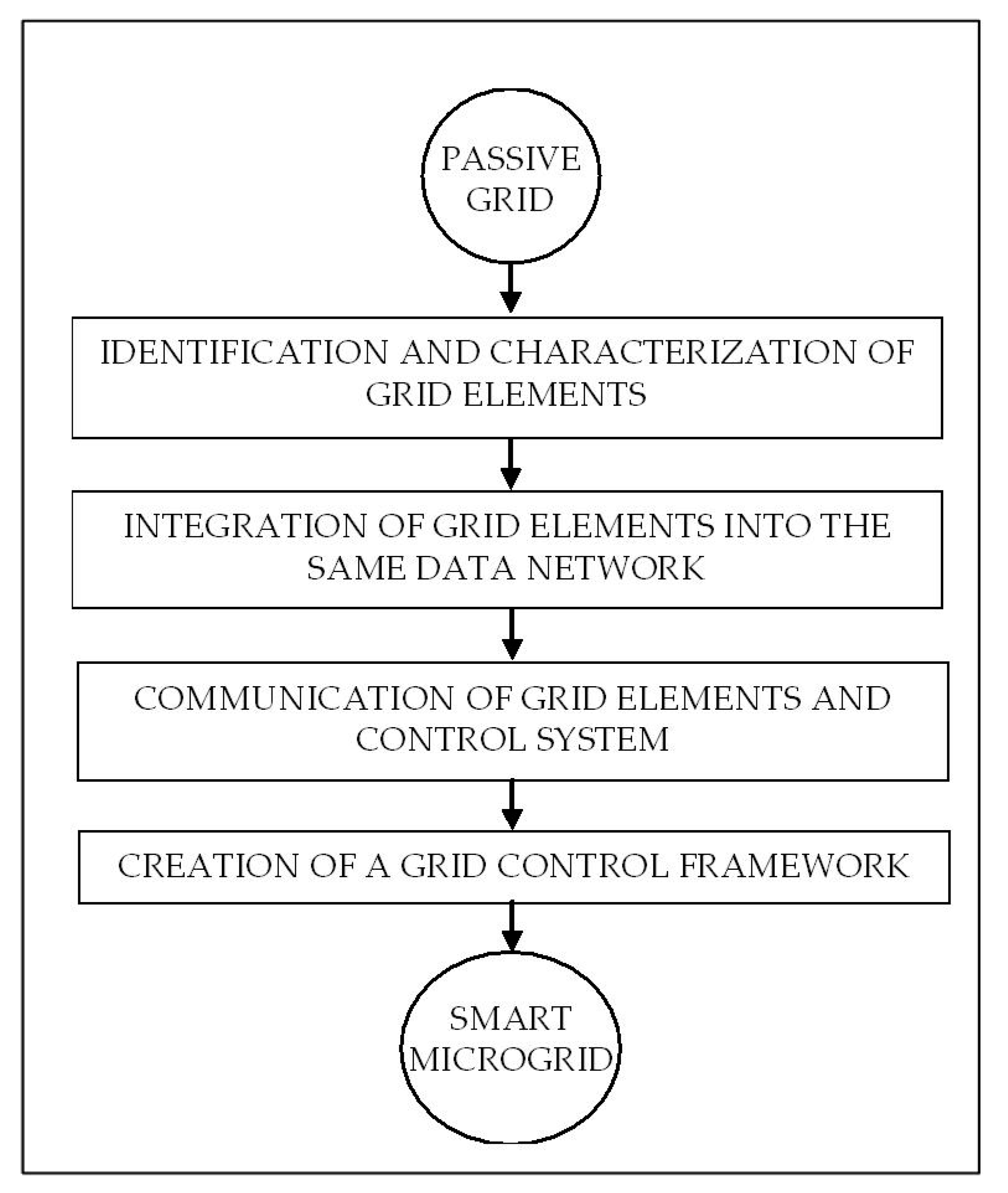
3. Procedure for the Conversion of a Network Section into a Smart Microgrid
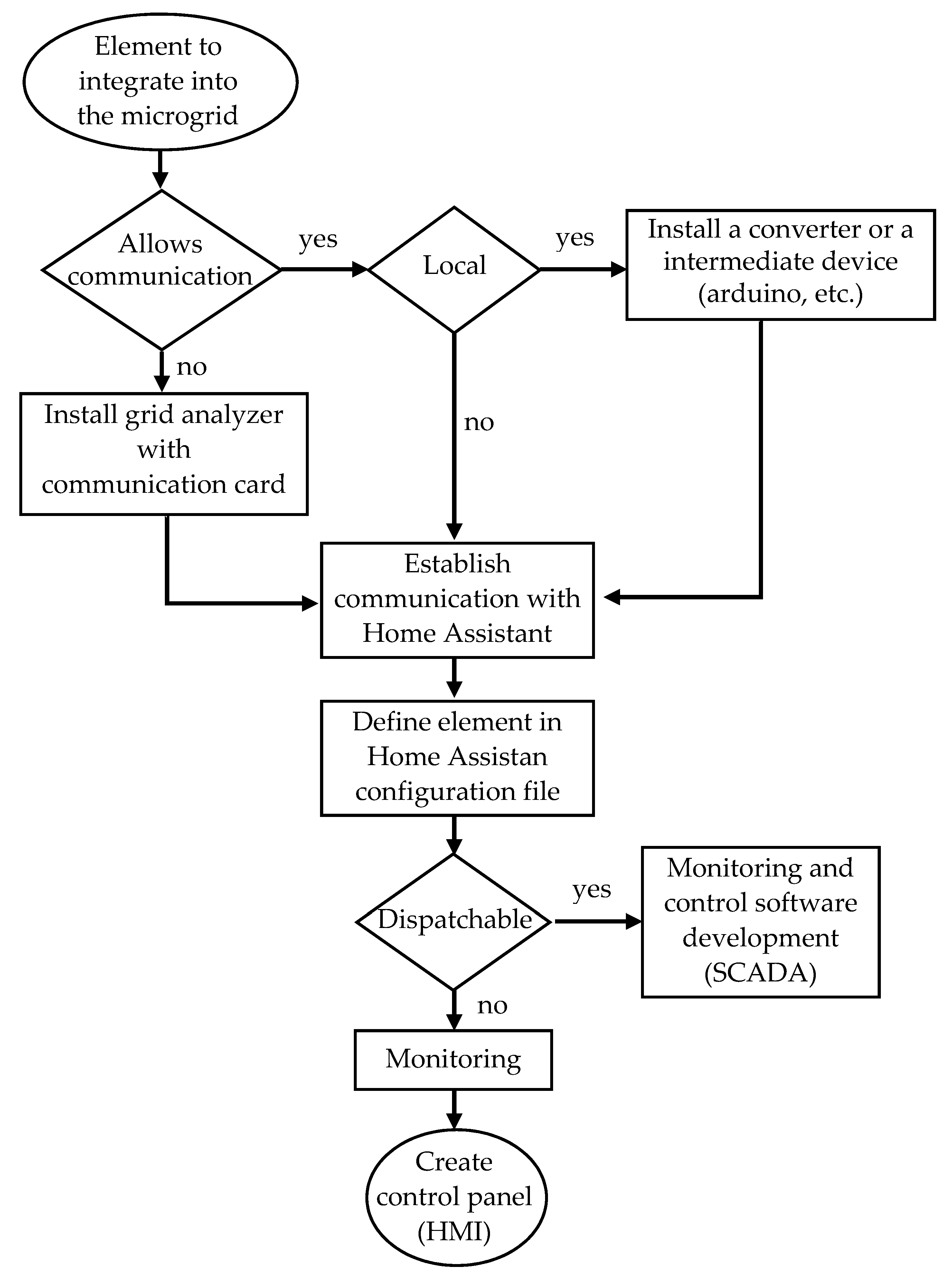
- Modbus TCP/IP (Transmission Control Protocol/Internet Protocol): it is based on a client/server architecture and allows communication over an Ethernet grid, no CRC required. It is the most common protocol. A name must be assigned to the element, and the IP address defined, the type of communication, and the communication port (502), as follows:- name: Photovoltaic1 # name assigned to the element.type: tcp # protocol typehost: 192.168.15.75 # IP addressport: 502 # communication port
- Modbus RTU: this is a master/slave architecture for linking a control system to a Remote Terminal Unit (RTU) via a serial port. Commonly, the master is an HMI or a SCADA system that sends a request and the slave is a sensor or PLC that returns a response. A CRC (Cyclic Redundancy Checksum) is used as an error-checking mechanism and as a procedure to ensure data reliability. A name must be assigned to the element, the type defined, and method of communication, the communication port, baudrate, stopbits, bytesize and parity, all given, as follows:- name: Battery1 # name assigned to the element.type: serial # type of communication.method: rtu # method of communication.port:/dev/ttyUSB0 # port (USB in this case).baudrate: 19200stopbits: 1bytesize: 8parity: E
- Modbus RTU over TCP: it is a combination of Modbus TCP and Modbus RTU. It is based on client/server architecture for communications over Ethernet as Modbus TCP/IP but uses a CRC as Modbus RTU. The same issue as in TCP/IP must be defined.- name: SmallWindTurbine1type: rtuovertcphost: 192.168.15.87port: 7128
- HTTP protocol: The element must be defined, a name assigned, the http address for the information required, and the scan interval provided:sensor:- platform: command_linename: “Pump1”command: “curl -s ‘http://admin:[email protected]/io.cgi?’ (accessed on 1 January 2021) | awk ‘/^relays/{print substr($2, 1, 1)}’”scan_interval: 1
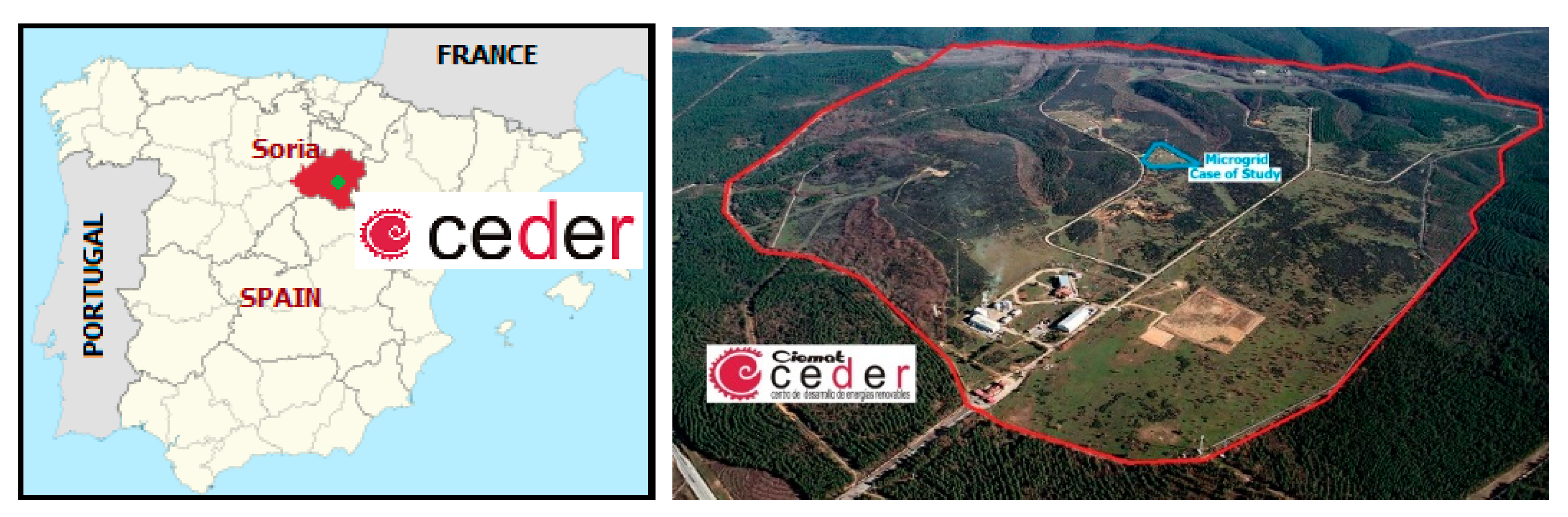
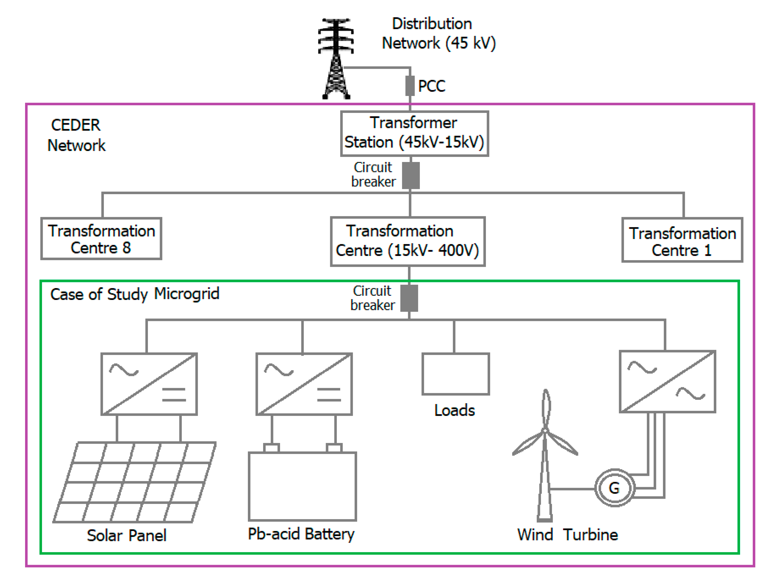
4. Case Study
4.1. Identification and Specification of the Grid Components
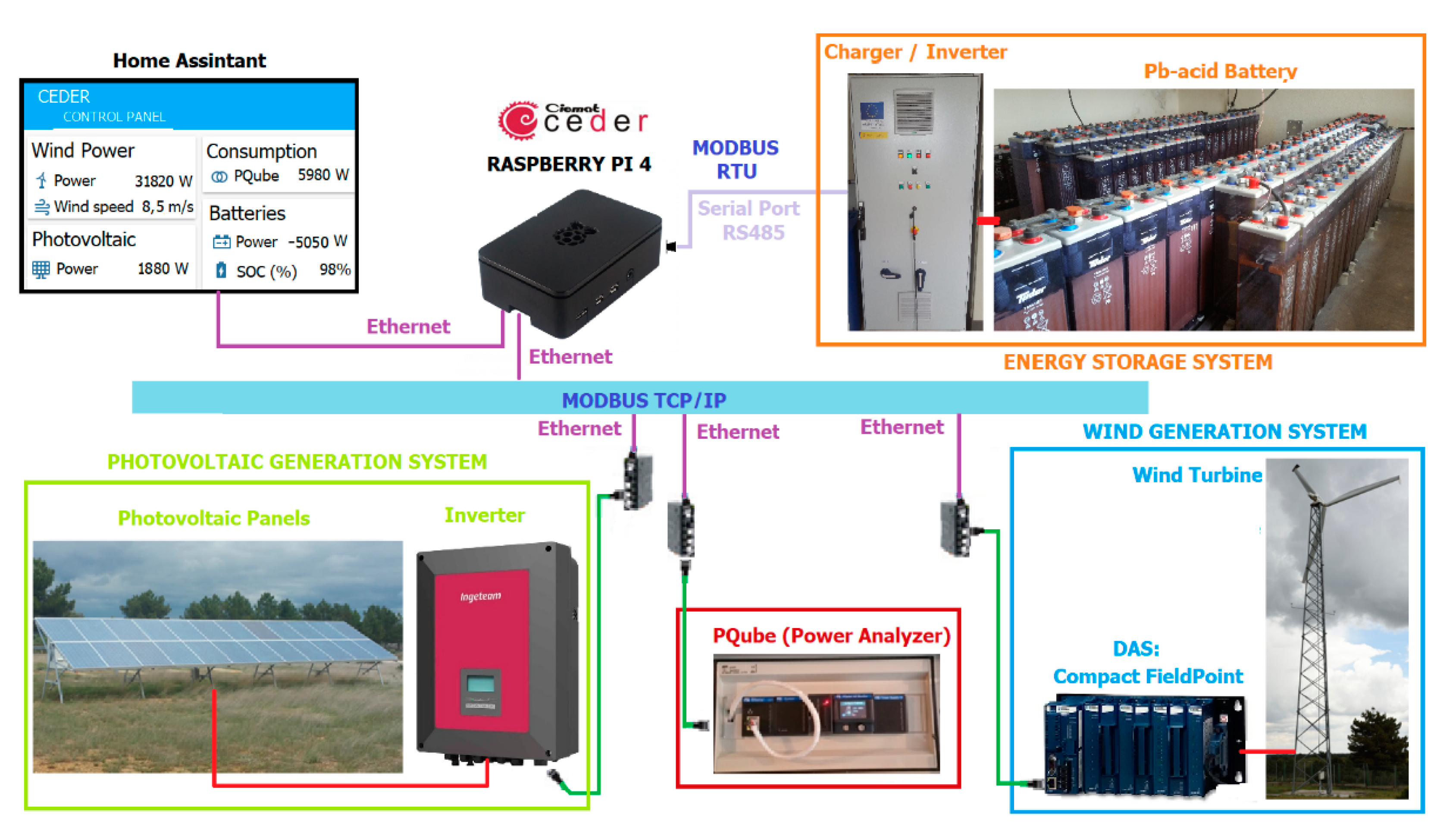
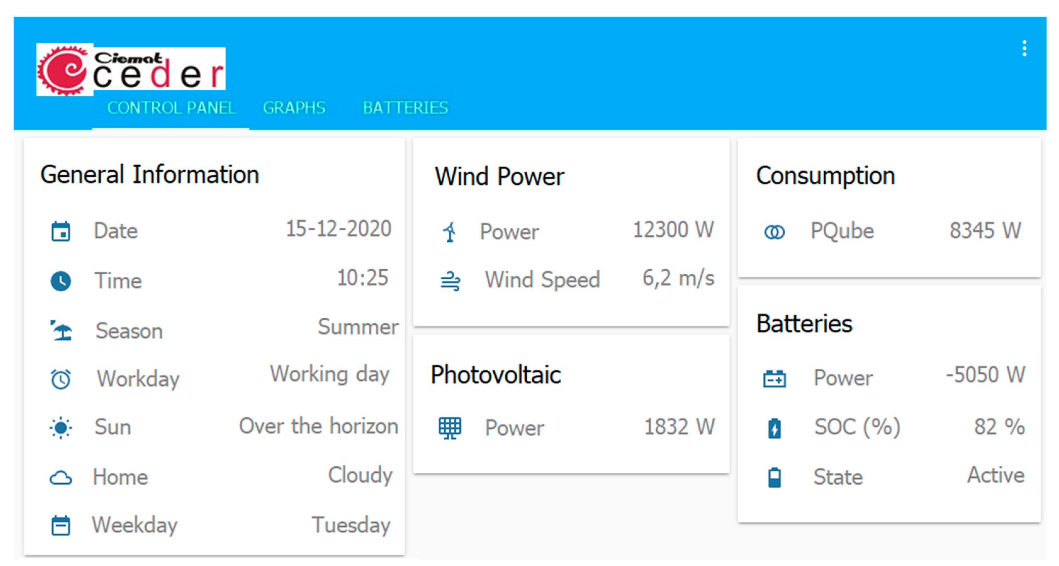
- Photovoltaic: four series of six photovoltaic panels (210 W each one) for a total of 5 kW. Panels are polycrystalline silicon and are assembled on a floor structure with a variable inclination angle and are connected to a 5 kW inverter (Ingeteam-Ingecon Sun Lite).It is necessary to connect with the inverter to be able to read instantaneous power values. This model of inverter has a network card included which allows to connect it directly to the CEDER data network (Ethernet) and enables communication via Modbus TCP/IP.
- Wind power: there is a three-blade horizontal axis small wind turbine. Diameter 15 m and 50 kW power. It is operating leeward.A National Instruments FieldPoint is installed to measure variables such as wind speed, power, etc. and can be connected to the CEDER data network via Modbus TCP/IP protocol. With the installation of this element, it is possible to have a data register as this wind turbine does not have a previous connection.
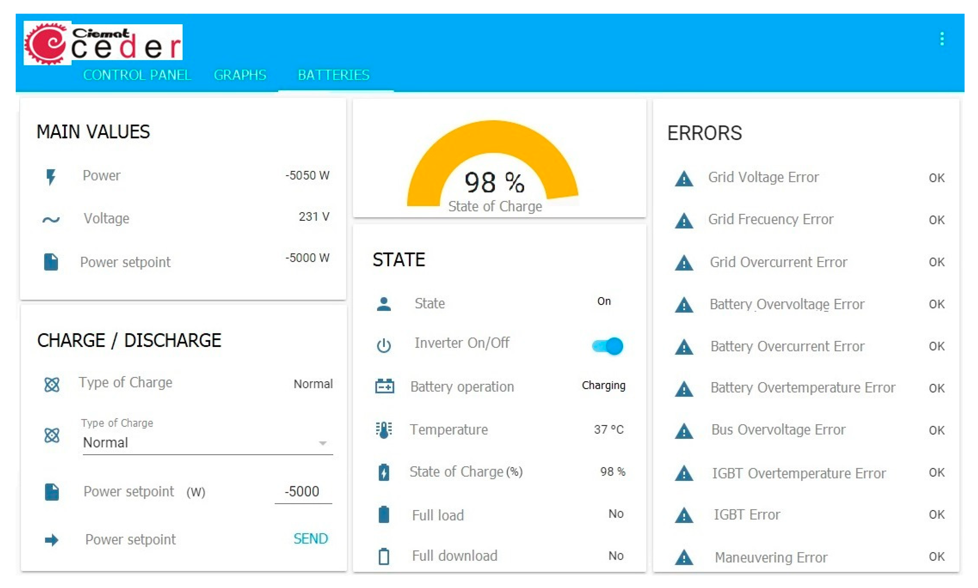
- Battery energy storage system (BESS): formed by 120 Pb-acid cells. Total voltage: 240 V, capacity: 1080 Ah at 120 h (C120). BESS is connected to a 50 kW charger/regulator/inverter.The inverter is connected with a SCADA for battery control via RS485 to the serial port of a computer. The control system of the microgrid to be developed will communicate locally with the charger using Modbus RTU protocol.
- Consumption: loads of the microgrid come from the buildings located inside the part of the CEDER where the laboratories and workshops are located. Consumption is measured by means of power quality/grid analyzers (PQube) that allow connection to the CEDER’s data network via Ethernet and Modbus TCP/IP communication. These are installed in the low voltage part of the transformation centre. For this case study, there are no critical loads that need to be supplied in the event of failure or serious disturbance of the microgrid.
4.2. Integration of Grid Elements into the Same Data Network
4.3. Establish Communication between Grid Elements
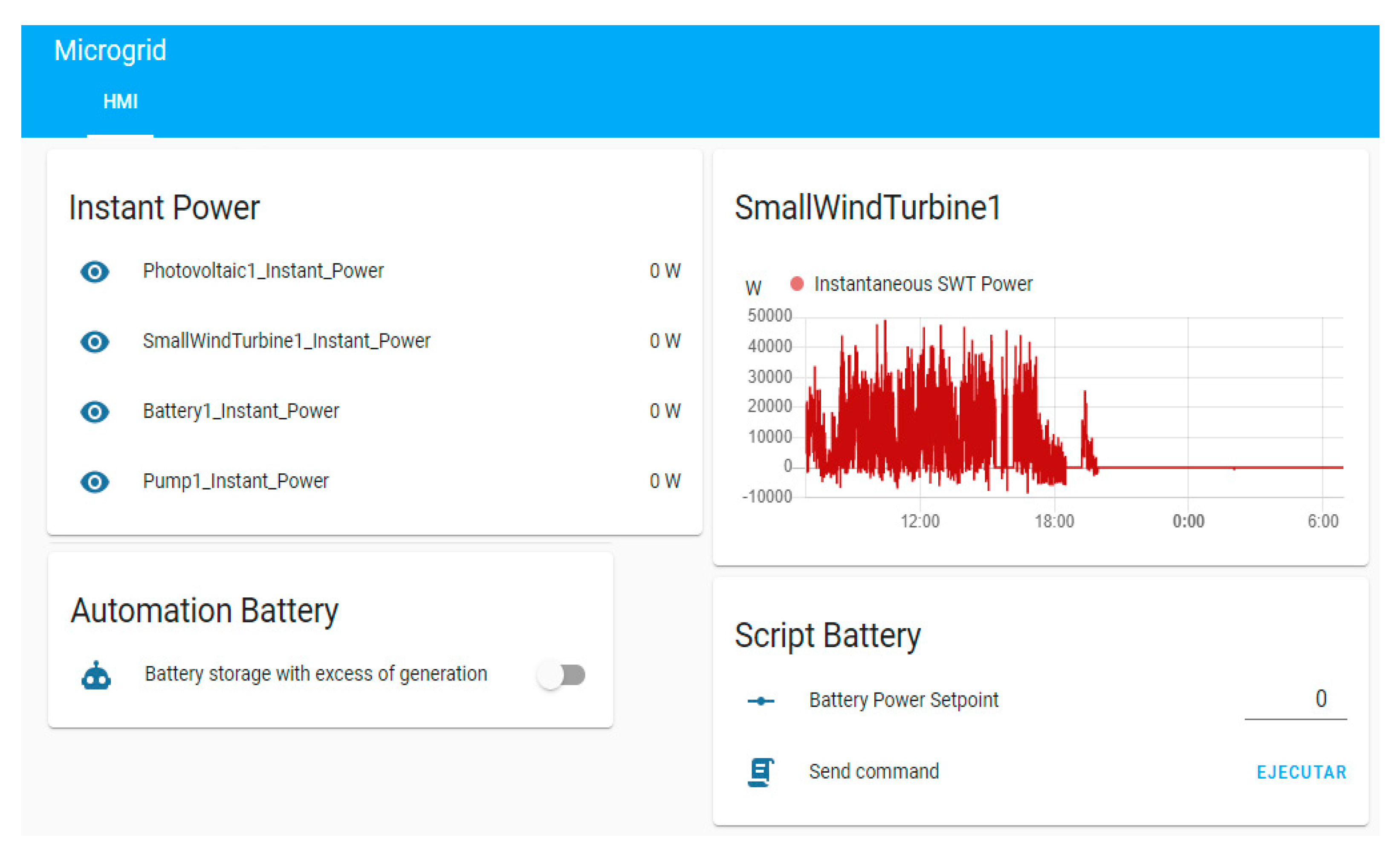
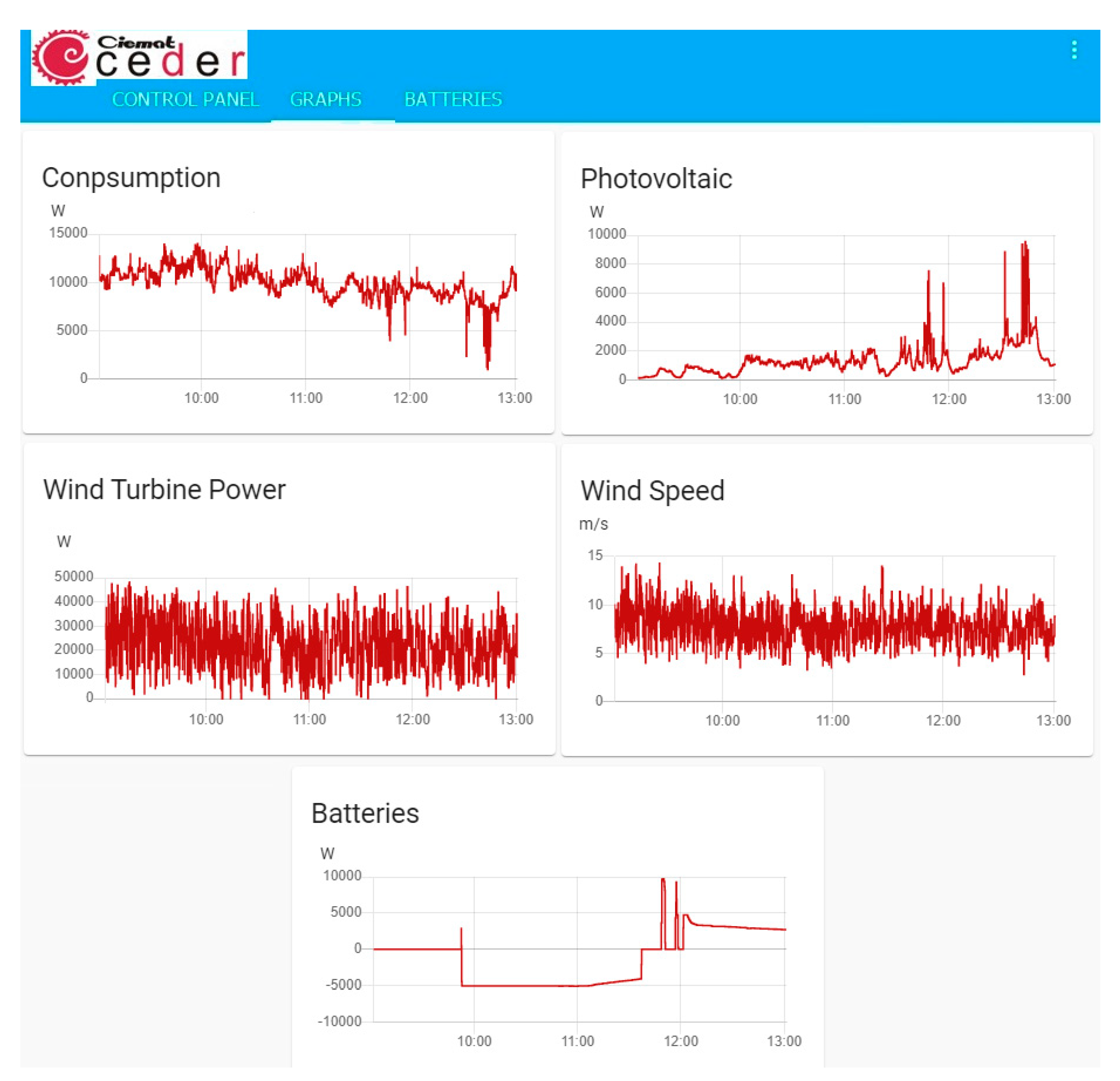
4.4. Control Grid Framework Creation
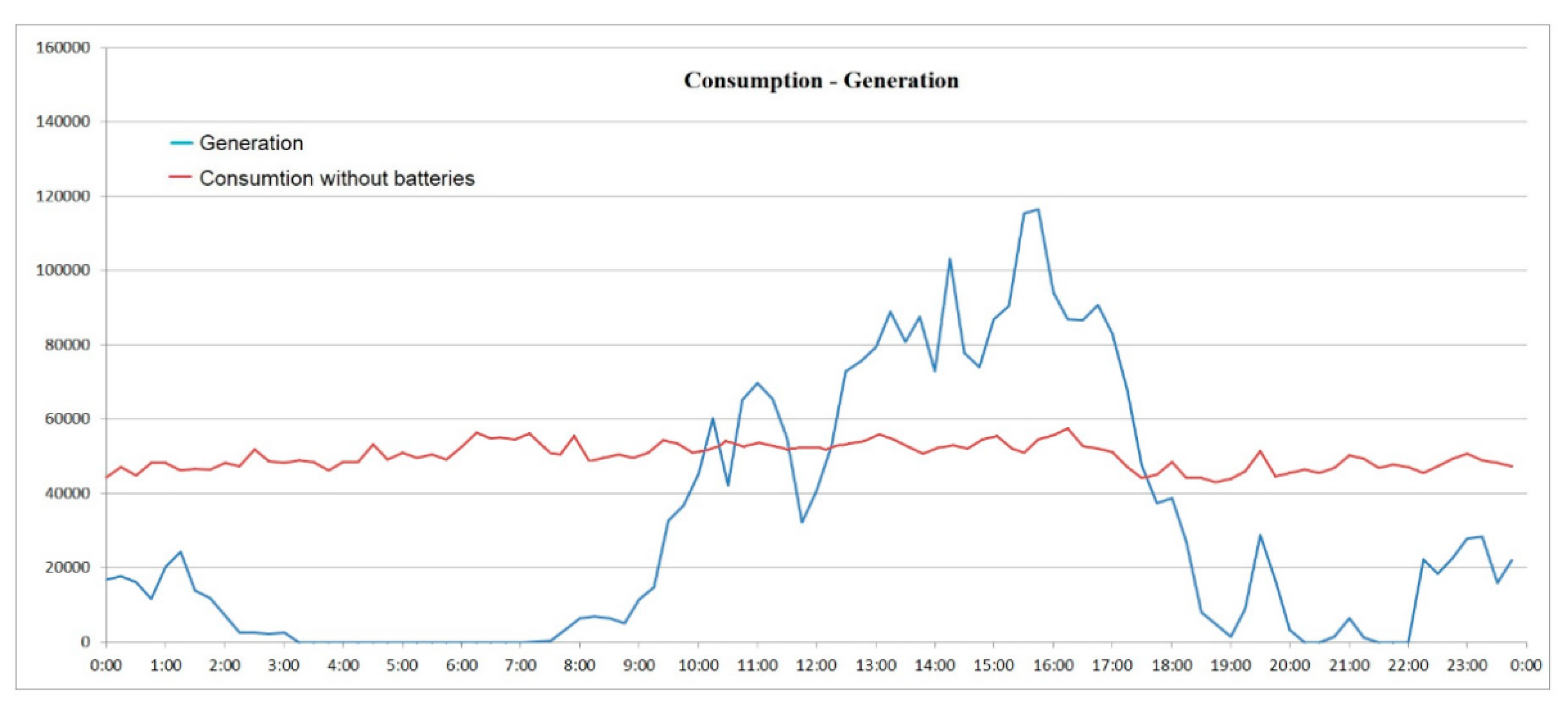
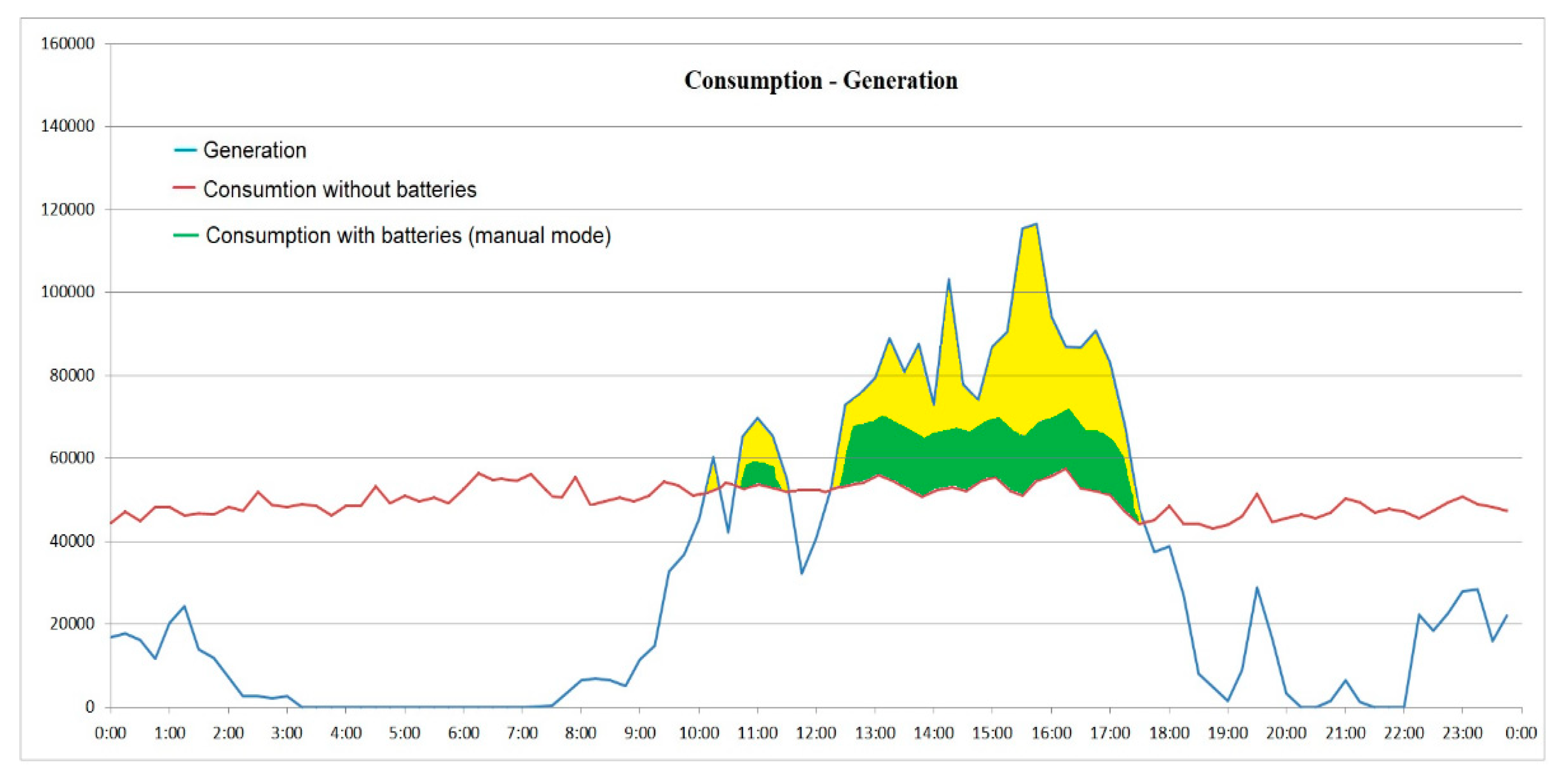
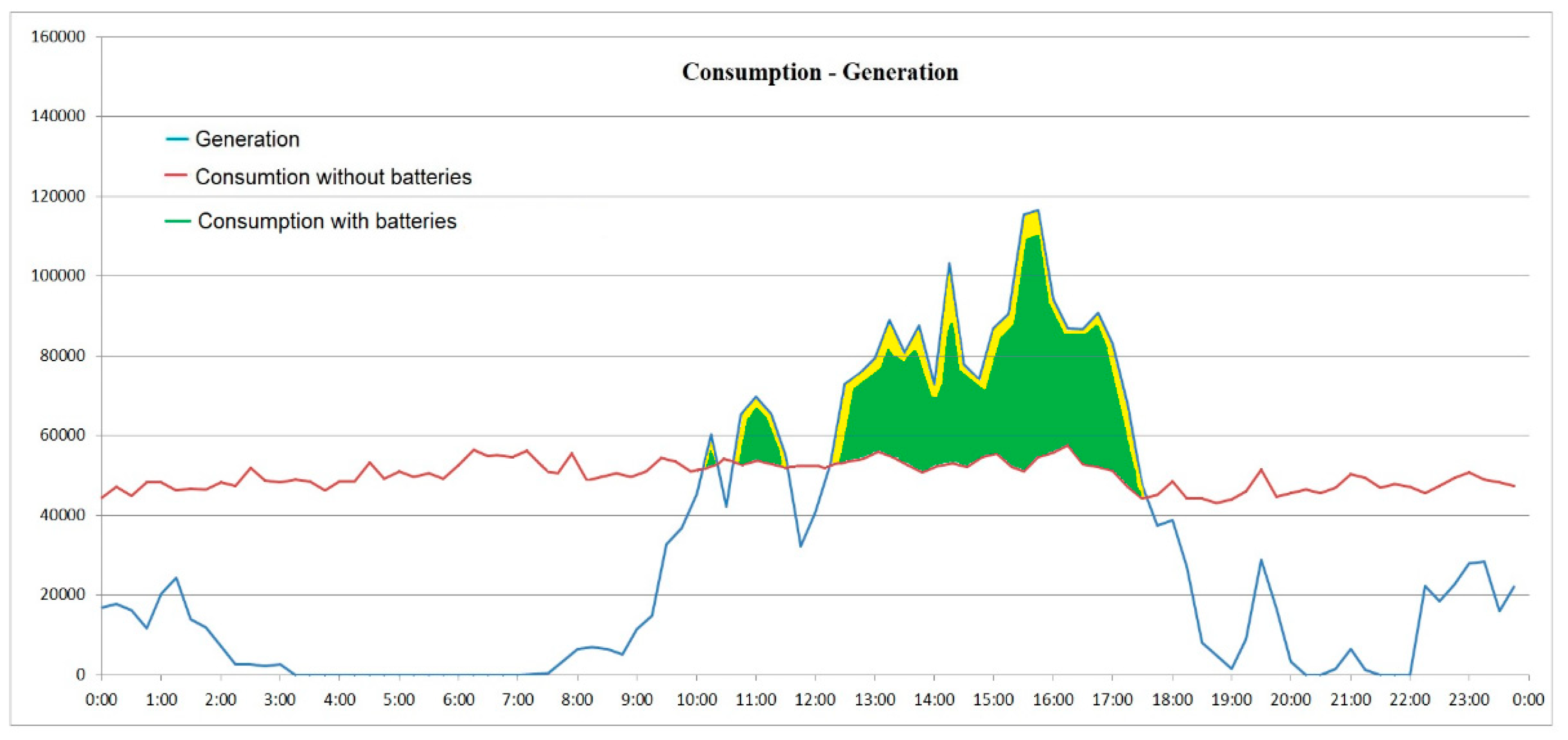
5. Conclusions
Author Contributions
Funding
Institutional Review Board Statement
Informed Consent Statement
Data Availability Statement
Acknowledgments
Conflicts of Interest
References
- Ton, D.T.; Smith, M.A. The U.S. Department of Energy’s Microgrid Initiative. Electr. J. 2012, 25, 84–94. [Google Scholar] [CrossRef]
- Divya, K.C.; Østergaard, J. Battery energy storage technology for power systems-An overview. Electr. Power Syst. Res. 2009, 79, 511–520. [Google Scholar] [CrossRef]
- Sachs, T.; Gründler, A.; Rusic, M.; Fridgen, G. Framing Microgrid Design from a Business and Information Systems Engineering Perspective. Bus. Inf. Syst. Eng. 2019, 61, 729–744. [Google Scholar] [CrossRef] [Green Version]
- Jirdehi, M.A.; Tabar, V.S.; Ghassemzadeh, S.; Tohidi, S. Different aspects of microgrid management: A comprehensive review. J. Energy Storage 2020, 30, 101457. [Google Scholar] [CrossRef]
- Li, Q.; Xu, Z.; Yang, L. Recent advancements on the development of microgrids. J. Mod. Power Syst. Clean Energy 2014, 2, 206–211. [Google Scholar] [CrossRef] [Green Version]
- Jia, Y.; Lyu, X.; Lai, C.S.; Xu, Z.; Chen, M. A retroactive approach to microgrid real-time scheduling in quest of perfect dispatch solution. J. Mod. Power Syst. Clean Energy 2019, 7, 1608–1618. [Google Scholar] [CrossRef] [Green Version]
- Kaur, A.; Kaushal, J.; Basak, P. A review on microgrid central controller. Renew. Sustain. Energy Rev. 2016, 55, 338–345. [Google Scholar] [CrossRef]
- Ahmad Khan, A.; Naeem, M.; Iqbal, M.; Qaisar, S.; Anpalagan, A. A compendium of optimization objectives, constraints, tools and algorithms for energy management in microgrids. Renew. Sustain. Energy Rev. 2016, 58, 1664–1683. [Google Scholar] [CrossRef]
- Gharavi, H.; Ghafurian, R. Smart Grid: The Electric Energy System of the Future; Gharavi, H., Ghafurian, R., Eds.; IEEE: New York, NY, USA, 2011; Volume 99, pp. 917–921. [Google Scholar]
- Teufel, S.; Teufel, B. The Crowd Energy Concept. J. Electron. Sci. Technol. 2014, 12, 263–269. [Google Scholar] [CrossRef]
- Aslam, W.; Soban, M.; Akhtar, F.; Zaffar, N.A. Smart meters for industrial energy conservation and efficiency optimization in Pakistan: Scope, technology and applications. Renew. Sustain. Energy Rev. 2015, 44, 933–943. [Google Scholar] [CrossRef]
- Khan, K.R.; Siddiqui, M.S.; Saawy, Y.A.; Islam, N.; Rahman, A. Condition Monitoring of a Campus Microgrid Elements using Smart Sensors. Procedia Comput. Sci. 2019, 163, 109–116. [Google Scholar] [CrossRef]
- Vargas-Salgado, C.; Aguila-Leon, J.; Chiñas-Palacios, C.; Hurtado-Perez, E. Low-cost web-based Supervisory Control and Data Acquisition system for a microgrid testbed: A case study in design and implementation for academic and research applications. Heliyon 2019, 5, e02474. [Google Scholar] [CrossRef] [Green Version]
- Kunicki, M.; Borucki, S.; Zmarzły, D.; Frymus, J. Data acquisition system for on-line temperature monitoring in power transformers. Measurement 2020, 161, 107909. [Google Scholar] [CrossRef]
- Nikolic, D.; Negnevitsky, M. Smart Grid in Isolated Power Systems–Practical Operational Experiences. Energy Procedia 2019, 159, 466–471. [Google Scholar] [CrossRef]
- Eissa, M.M.; Awadalla, M.H.A. Centralized protection scheme for smart grid integrated with multiple renewable resources using Internet of Energy. Glob. Transit. 2019, 1, 50–60. [Google Scholar] [CrossRef]
- Shuai, Z.; Sun, Y.; Shen, Z.J.; Tian, W.; Tu, C.; Li, Y.; Yin, X. Microgrid stability: Classification and a review. Renew. Sustain. Energy Rev. 2016, 58, 167–179. [Google Scholar] [CrossRef]
- Hanah, A.; Farook, R.; Elias, S.J.; Rejab, M.R.A.; Fadzil, M.F.M.; Husin, Z. IoT Room Control And Monitoring System Using Rasberry Pi. In Proceedings of the 2019 4th International Conference and Workshops on Recent Advances and Innovations in Engineering (ICRAIE), Kedah, Malaysia, 27–29 November 2019; pp. 1–4. [Google Scholar] [CrossRef]
- Singh, S.; Weeber, M.; Birke, K.P.; Sauer, A. Development and Utilization of a Framework for Data-Driven Life Cycle Management of Battery Cells. Procedia Manuf. 2020, 43, 431–438. [Google Scholar] [CrossRef]
- Li, W.; Rentemeister, M.; Badeda, J.; Jöst, D.; Schulte, D.; Sauer, D.U. Digital twin for battery systems: Cloud battery management system with online state-of-charge and state-of-health estimation. J. Energy Storage 2020, 30, 101557. [Google Scholar] [CrossRef]
- Kim, T.; Makwana, D.; Adhikaree, A.; Vagdoda, J.; Lee, Y. Cloud-Based Battery Condition Monitoring and Fault Diagnosis Platform for Large-Scale Lithium-Ion Battery Energy Storage Systems. Energies 2018, 11, 125. [Google Scholar] [CrossRef] [Green Version]
- Anandan, N.; Sivanesan, S.; Rama, S.; Bhuvaneswari, T. Wide area monitoring system for an electrical grid. Energy Procedia 2019, 160, 381–388. [Google Scholar] [CrossRef]
- Petrollese, M.; Valverde, L.; Cocco, D.; Cau, G.; Guerra, J. Real-time integration of optimal generation scheduling with MPC for the energy management of a renewable hydrogen-based microgrid. Appl. Energy 2016, 166, 96–106. [Google Scholar] [CrossRef]
- Kennedy, J.; Ciufo, P.; Agalgaonkar, A. Intelligent load management in microgrids. IEEE Power Energy Soc. Gen. Meet. 2012, 1–8. [Google Scholar] [CrossRef] [Green Version]
- Kornas, T.; Wittmann, D.; Daub, R.; Meyer, O.; Weihs, C.; Thiede, S.; Herrmann, C. Multi-Criteria Optimization in the Production of Lithium-Ion Batteries. Procedia Manuf. 2020, 43, 720–727. [Google Scholar] [CrossRef]
- Augustins, E.; Jaunzems, D.; Rochas, C.; Kamenders, A. Managing energy efficiency of buildings: Analysis of ESCO experience in Latvia. Energy Procedia 2018, 147, 614–623. [Google Scholar] [CrossRef]
- GE Digital. Advanced Energy Management System (AEMS). Available online: https://www.ge.com/digital/applications/transmission/advanced-energy-management-system-aems (accessed on 1 March 2021).
- Operation Technology, Inc. Etap Powering Success. Available online: https://etap.com/es/home (accessed on 3 March 2021).
- Open Systems International (OSI). Available online: https://www.osii.com/index.asp (accessed on 2 January 2021).
- Wattics. Available online: https://www.wattics.com/dashboard/ (accessed on 1 January 2021).
- Home Assistant. Available online: https://www.home-assistant.io/ (accessed on 3 March 2021).


| Software | Advantages | Disadvantages |
|---|---|---|
| Advance EMS–Platform [27] | Alarm notification Real-time readings and management Access control Historical data Desktop version | Paid license Only for Wind, PV, and Storage No smartphone version Development and configuration by the company |
| ETAP Energy Management System [28] | Alarm notification Real-time readings and management Access control Historical data Desktop version | Paid license No smartphone version Development and configuration by the company |
| Monarch TM–Open Systems International [29] | Alarm notification Real-time readings and management Access control Historical data Desktop and smartphone version | Paid license No readings and management for storage systems Development and configuration by the company |
| Wattics [30] | Read data from meters and sensors Alarm notification Real-time readings and management Access control Historical data Desktop and smartphone version | Paid license Development and configuration by the company |
| CMEMS (developed with Home Assistant [31] | Open-source No limitation on the type and number of equipment to be monitored and managed Alarm notification Real-time readings and management Access control Historical data Desktop and smartphone version Development and configuration by yourself |
Publisher’s Note: MDPI stays neutral with regard to jurisdictional claims in published maps and institutional affiliations. |
© 2021 by the authors. Licensee MDPI, Basel, Switzerland. This article is an open access article distributed under the terms and conditions of the Creative Commons Attribution (CC BY) license (https://creativecommons.org/licenses/by/4.0/).
Share and Cite
Izquierdo-Monge, O.; Peña-Carro, P.; Villafafila-Robles, R.; Duque-Perez, O.; Zorita-Lamadrid, A.; Hernandez-Callejo, L. Conversion of a Network Section with Loads, Storage Systems and Renewable Generation Sources into a Smart Microgrid. Appl. Sci. 2021, 11, 5012. https://0-doi-org.brum.beds.ac.uk/10.3390/app11115012
Izquierdo-Monge O, Peña-Carro P, Villafafila-Robles R, Duque-Perez O, Zorita-Lamadrid A, Hernandez-Callejo L. Conversion of a Network Section with Loads, Storage Systems and Renewable Generation Sources into a Smart Microgrid. Applied Sciences. 2021; 11(11):5012. https://0-doi-org.brum.beds.ac.uk/10.3390/app11115012
Chicago/Turabian StyleIzquierdo-Monge, Oscar, Paula Peña-Carro, Roberto Villafafila-Robles, Oscar Duque-Perez, Angel Zorita-Lamadrid, and Luis Hernandez-Callejo. 2021. "Conversion of a Network Section with Loads, Storage Systems and Renewable Generation Sources into a Smart Microgrid" Applied Sciences 11, no. 11: 5012. https://0-doi-org.brum.beds.ac.uk/10.3390/app11115012