Article

Switching Control Strategy for Oscillating Water Columns Based on Response Amplitude Operators for Floating Offshore Wind Turbines Stabilization

Automatic Control Group—ACG, Department of Automatic Control and Systems Engineering, Faculty of Engineering of Bilbao, Institute of Research and Development of Processes—IIDP, University of the Basque Country—UPV/EHU, Po Rafael Moreno no3, 48013 Bilbao, Spain
*
Author to whom correspondence should be addressed.
Submission received: 20 May 2021 / Revised: 2 June 2021 / Accepted: 4 June 2021 / Published: 5 June 2021
(This article belongs to the Special Issue New Trends in Automation Control Systems and Their Applications)

Abstract

:
In this article, a new strategy for switching control has been proposed with the aim of reducing oscillations in floating offshore wind turbines. Such oscillations lead to a shortage in the system’s efficiency, lifespan and harvesting capability of wind and wave energies. In order to study the decreasing of undesired oscillations in the system, particularly in pitch and top tower fore-aft movements, a square-shaped platform barge equipped with four symmetric oscillating water columns has been considered. The oscillating water columns’ air flux valves allow to operate the air columns so that to control the barge movements caused by oscillatory motion of the waves. In order to design the control scheme, response amplitude operators have been used to evaluate the performance of the system for a range of wave frequency profiles. These response amplitude operators analysis makes it possible to implement a switching control strategy to adequately regulate the valves opening/closing transition. The obtained results show that the proposed controlled oscillating water column-based barge present a better performance compared to the traditional barge one. In the case study with the period of 10 s, the results indicate the significant oscillation reduction for the controlled oscillating water column-based system compared to the standard barge system by 30.8% in pitch angle and 25% in fore-aft displacement.

1. Introduction

The sustainable resources of renewable energies such as wind and wave power are attracting more and more attention because of climate change and global warming impacts [1]. To fight against these issues, it is vital to develop the infrastructures of wind and wave supplies [2]. Floating Offshore Wind Turbines (FOWT) have played an unprecedented role in capturing more clean and renewable wind and wave resources and generating more electricity [3]. Some classes of such turbines have been deployed in vast areas available in seaside towns in countries including the USA, Spain, Japan, South-Korea, Norway [4] and Morocco [5].
FOWTs’ structure offers a possibility for adding Oscillating Water Columns (OWC) [6], which is the most investigated class of wave energy converters [7], for harnessing both wind and wave power supplies. The combined system of FOWT-OWCs can have a great impact in balancing the system’s costs, taking advantages of shared operation and maintenance and common grid infrastructure [8]. Also, it can increase the smoothed power output and efficiency of the system [9].
However, one of the challenges ahead is stabilization of FOWTs to alleviate undesired platform’s vibrations and to harvest the maximum possible energy [10]. Such undesired motions reduce the aerodynamic efficiency, shorten the fatigue life of tower and increase stresses on blades, rotor shaft, yaw bearing and tower base [11]. Therefore, it is important to restrain the FOWT’s platform motions within an adequate range [12].
In order to decrease the FOWTs’ motions in different modes, authors have applied various methods to deal with the problem [13]. The application of heave plates attached to the spar-type FOWT with the aim of motion stabilization was introduced by W. Yang et al. [14]. M. Kamarlouei et al. in [15] conducted an experimental study to reduce the heave and pitch amplitude using the added catenary mooring cables as well as installation of the Wave Energy Converters (WEC) on a FOWT. Several authors have proposed the usage of inerters in barge-type FOWT to control the tower displacements such as Y. Zhang et al. in [16] and Y. Hu et al. in [17]. X. Wei et al. in [18] proposed the use of two different liquid column dampers to control the vibration in a spar-type FOWTs. With the use of the bidirectional tuned liquid column damper and the tuned mass damper, the barge is able to decrease the pitch and roll angles in the FOWT. Some papers have proposed hybrid FOWT-WEC for multi-functional aims of wind and wave supplies extractions. J. Sarmiento et al. in [19] performed an experimental work to validate a novel hybrid FOWT-OWC semi-submersible floater. This combined system maximizes the wave energy production by chamber opening. Another alternative to deal with oscillatory behavior of a class of nonlinear systems has been proposed by M. Cooper et al. in [20].
A few articles have extended the application of combined barge-based FOWT-OWCs with consideration of full nonlinear equations of motion. J.M. Jonkman in [21] designed a square-shaped moonpool placed at the barge’s center that provides the option of adding an OWC within the tower of the wind turbine, but this hybrid system has not designed for the purpose of stabilization. P. Aboutalebi et al. in [22] analyzed the performance of the hybrid barge-type FOWT-OWCs under different sea states to increase the stability of the system. However, the introduced approaches have not proposed a strategy to control the valves of OWCs.
In this research article, the nonlinear barge-type model of NREL 5-MW baseline was investigated. Four OWCs have been housed within the barge in order to decrease the oscillations, particularly in pitch and top tower fore-aft modes, in the whole hybrid system under various sea states. With the usage of Response Amplitude Operators (RAO), a switching control strategy have been proposed to transient between opening/closing OWCs’ valves. The controlled OWC-based FOWT has been compared to the traditional barge platform to show the performance of the controlled hybrid system.
The rest of the manuscript is structured as: Section 2 explains the structure of hybrid FOWT-OWCs with its equations of motion. For the structure design, three platforms are considered including Standard barge platform, 4OWC-based barge platform with closed valves and 4OWC-based barge platform with open valves. Section 3 presents the problem statement in order to introduce the RAOs used for the proposed switching control strategy. The RAOs are used to analyze the dynamic response of the system. Section 4 considers a study case to study the efficiency of the proposed switching control under various sea states. Finally in Section 5, the conclusion of the results is presented.

2. Model Statement

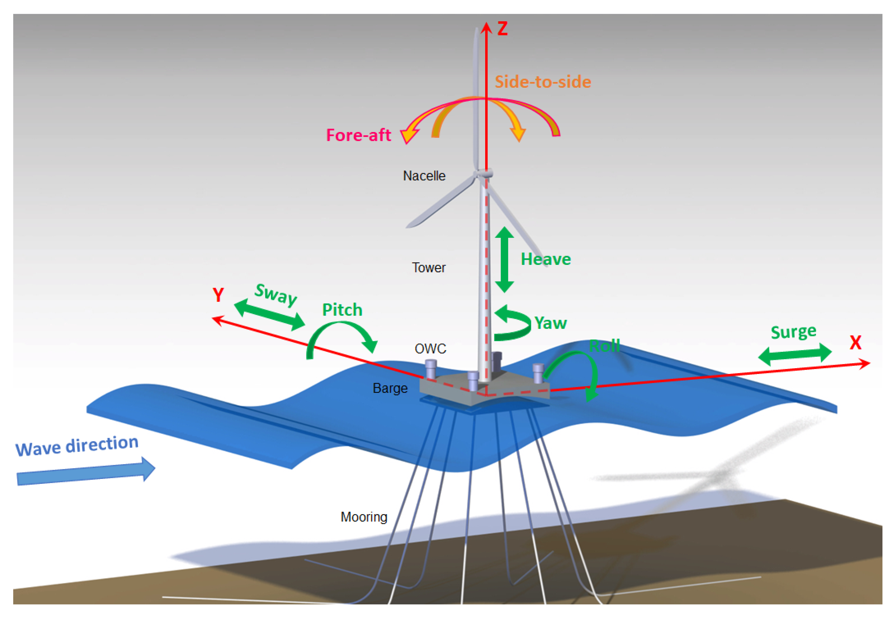
2.1. FOWT Description

In this research work, four OWCs are placed inside the platform’s corners as represented in Figure 1. The square-shaped platform is connected to the FOWT’s tower and ballasted with seawater to obtain a proper draft, which is not so shallow that it is vulnerable to continuous wave slamming. The platform is anchored through eight catenary cables to avoid it from drifting. Two of the lines from each corner of the barge’s bottom have a 45-degree angle from each other.
Mooring systems, made of eight catenary lines anchored to the floating support platform at fairlead connections, are applied to hold the floater against wind, waves and current. The opposite ends of the lines are moored to the seafloor. Such cables may be made of chain, steel, and/or synthetic fibers and are often a segmented combination of these materials [23]. Depending on environmental conditions, the tension on each cable changes. As the fairleads move with the platform in response to unsteady environmental loading, the restraining forces at the fairleads change with the changing cable tension. This means that the mooring system has an effective compliance for the stabilization of the system. In this study, wind and servo forces for yaw, pitch and generator control of the wind turbine have not been considered. Therefore, eight Degrees Of Freedom (DOF) are assessed namely surge, sway, heave, roll, pitch, yaw, fore-aft and side-to-side motions. The dynamic responses of the FOWT have been included in FAST in order to implement the nonlinear equations of motion. In Table 1, The detailed features of the wind turbine are presented.
Moreover, the features of the barge platform and the platform with OWCs are represented in Table 2.

2.2. Equations of Motions in the FOWT

In this study, the input is unidirectional regular waves. Besides, Airy wave theory is considered to explain its surface dynamics [25]:
z ( t ) = A sin ( ω t ) = A sin ( 2 π f t ) = A sin 2 π λ c t
where the propagation velocity and the wave amplitude from SWL to the wave crest may be defined as c = λ f and A, respectively. Also, the wavelength ( λ ) is calculated by measuring the distance between two crests. Equation (1) expresses the temporal variation of a wave as a macroscopic representation of the oscillating motion of water particles at a specific point [26]. A variable for the representation of the spatial dimension in the wave’s front direction may be represented for transferring the oscillating behavior to any point on the wave’s surface. Hence, Equation (1) may be rewritten as follows [27]:
z ( x , t ) = A sin 2 π λ ( c t x )
having the wave number as k = 2 π / λ , Equation (2) can be written as:
z ( x , t ) = A sin ( ω t k x ) = H 2 sin ( ω t k x )
where H is wave height between the wave trough and wave crest.
After describing the unidirectional regular waves, the equations of the FOWT’s motions are described. The complete nonlinear equations of motion in time-domain for the floating wind turbine with a platform equipped by OWCs may be given by:
M i j ( q , u , t ) q ¨ j = f i ( q , q ˙ , u , t )
where M i j and u are the inertia mass components and the control inputs respectively. q is the system’s states and t is time. q j ¨ is the second time derivative of the jth DOFs and f i is the component of the force function linked to ith DOF. Also, the parameter of the equation’s right-hand side is the generalized forces imposing to the system consisting of the aerodynamic load on the blades and the nacelle, hydrodynamic force on the platform, elastic and servo forces.
The system’s frequency-dominant equations of motion may be described by:
I F O W T ( ω ) q ¨ + B F O W T ( ω ) q ˙ + C F O W T q = f F O W T ( ω ) + f P T O ( ω )
here I F O W T is the inertia matrix, B F O W T is the damping matrix and C F O W T includes stiffness coefficients. f F O W T ( ω ) stands for the hydrodynamic force and viscous drag of the waves on the platform. f P T O ( ω ) symbolizes as the load induced by the Power-Take-Off (PTO) equipment. q from Equation (5) can be expressed by:
q = s u r g e s w a y h e a v e r o l l p i t c h y a w f o r e - a f t s i d e - t o - s i d e
The FOWT ’s inertia components can be expressed as follows:
I F O W T ( ω ) = A H y d r o ( ω ) + M P l a t f o r m + M T o w e r
here M P l a t f o r m and M T o w e r stand for platform and tower mass matrices, respectively. Platform mass matrix may be defined by:
M P l a t f o r m = m 1 0 0 0 L Z m 1 L Y m 1 0 m 2 0 L Z m 2 0 L X m 2 0 0 m 3 L Y m 3 L X m 3 0 0 L Z m 2 L Y m 3 β 1 L X L Y m 3 L X L Z m 2 L Z m 1 0 L X m 3 L X L Y m 3 β 2 L Y L Z m 1 L Y m 1 L X m 2 0 L X L Z m 2 L Y L Z m 1 β 3
where the diagonal elements may be described as:
β 1 = I 44 + L Z 2 m 2 + L Y 2 m 3
β 2 = I 55 + L X 2 m 3 + L Z 2 m 1
β 3 = I 66 + L Y 2 m 1 + L X 2 m 2
here m 1 , m 2 and m 3 represent the inertial mass, which are equal, in translational directions. I 44 , I 55 and I 66 stand for the inertial mass in rotational directions about the x-axis, y-axis, z-axis. L X , L Y and L Z express the position of the structure’s center of mass in SWL coordinates. The 8 × 8 mass matrix of the tower includes components relating both tower’s bending with its rigid heave motion. A H y d r o represents the platform’s added mass in frequency domain that can be obtained by WAMIT from the panel radiation program.
Equation (6) represents the system’s states with the six first ones for the platform displacements and the two last ones for the tower bending movements.
The stiffness matrix C F O W T is defined as:
C F O W T = C H y d r o + C M o o r i n g + C T o w e r
where C H y d r o is the platform’ hydrostatic restoring matrix obtained by WAMIT and C M o o r i n g contains the mooring lines spring stiffness coefficients and C T o w e r is the tower stiffness matrix.
The damping matrix is given by:
B F O W T ( ω ) = B H y d r o ( ω ) + B T o w e r + B v i s c o u s + B c h a m b e r
where B H y d r o , B T o w e r and B v i s c o u s are the floating platform’s damping matrix, damping matrix of the flexible tower and the nonlinear viscous drag on the platform, respectively. B c h a m b e r is the the PTO’s effect on the overall dynamics represented as external force. It is assumed that the internal free surface acts similar to a piston so that the pressure is uniform within the chamber [26]. Hence, the external force can be described as follows:
f P T O ( ω ) = p ( ω ) S
here p and S are the pressure drop across the turbine and internal free surface area, respectively. Also, It is considered that the air is an ideal gas and the air compression-decompression is an isentropic process so that the time-dependent air density may be described as:
ρ = ρ a p p a 1 γ
here ρ a and p a are the density and pressure signifying the state of the chamber at rest, respectively. γ defines the heat capacity ratio of air. After linearizing the time derivative of Equation (15), the subsequent equation may be given by:
ρ ˙ = ρ a γ p a p ˙
The linearized mass flow within the turbine may be described as [28]:
m ˙ = d ( ρ V ) d t = ρ a γ p a p ˙ V a + ρ a V ˙
here V and V a are the air volume through the chamber and the air volume in the chamber in an undisturbed condition, respectively.
By non-dimensional turbo-machinery nomenclature, a Wells turbine with diameter D and rotational velocity N is considered by a linear relation between the pressure and flow coefficients:
Ψ = K Φ
where the pressure and flow coefficients are described as:
Ψ = p ρ a N 2 D 2
Φ = m ˙ ρ a N D 3
Considering the pressure drop as proportional to the flow rate, nondimensionalization is used. Therefore, the linear relation may be given as follows:
Ψ c = K c Φ c
here the pressure and flow coefficients can be given by:
Ψ c = p ρ a g H
Φ c = 2 π m ˙ ρ a ω S H
here g is the acceleration of gravity. Hence, introducing Equations (21)–(23) into Equation (17), the mass flow within the turbine can be expressed by:
m ˙ ( ω ) = S ω 2 π g K c
Using combination of Equations (17) and (24), the pressure complex amplitude is expressed by:
p ^ ( ω ) = i ω Γ S ω 1 + ε Γ 2 V ^ ω 2 ε Γ 2 S ω 1 + ε Γ 2 V ^
here V ^ is the complex amplitude of the air volume oscillation and the constants Γ and ε may be expressed as:
Γ = 2 π ρ a g K c
ε = V a γ p a S
Conferring to Equations (14) and (25), the PTO force may be obtained by:
f ^ P T O ( ω ) = i ω B P T O q ^ r + ω 2 K P T O q ^ r
where q ^ r is the complex amplitude of the relative displacement. Based on the aforementioned Equation (25), the PTO damping and stiffness components can be described by:
B P T O ( ω ) = Γ S ω 1 + ε Γ 2
K P T O ( ω ) = ε Γ 2 S ω 2 1 + ε Γ 2
Finally, the system’s frequency-dominant equations of motion for the 8-DOF FOWT, described in Equation (5), is obtained as follows:
I F O W T ( ω ) q ^ · · + ( B F O W T ( ω ) + B P T O ( ω ) ) q ^ · + ( C F O W T + K P T O ( ω ) ) q ^ = f F O W T ( ω )
The element on the right-hand side of Equation (31) may be expressed by:
f F O W T ( ω ) = f H y d r o ( ω ) + f v i s c o u s ( ω )
here f v i s c o u s is the viscous force and f H y d r o is the hydrodynamic force of the waves on the platform. f H y d r o can be obtained from the panel diffraction program of WAMIT.

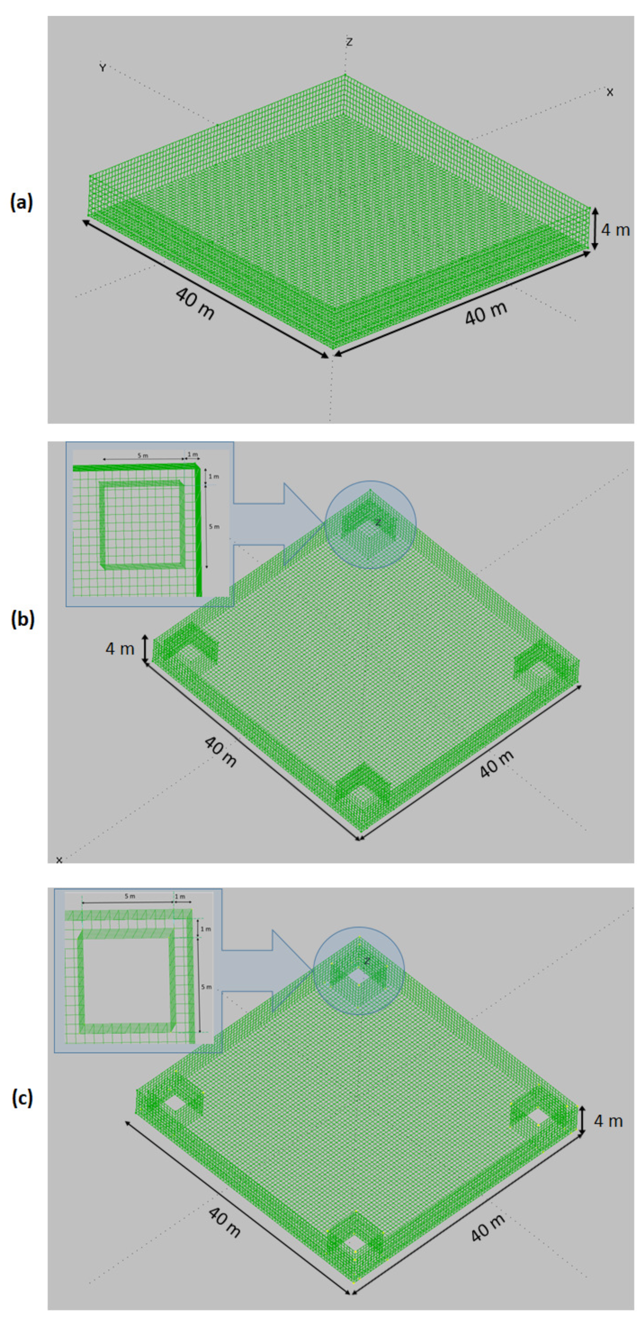
2.3. Platforms’ Design and Advanced Computations

Using MultiSurf software, the geometry of the platforms can be designed. Three varied platforms have been compared. Considering the first platform, It is a square-shaped barge called standard barge platform, shown in Figure 2a. On the other hand, the second model is an OWC-based barge platform with four OWCs housed at the platform’s corners when the OWCs’ valves are closed as illustrated in Figure 2b. Figure 2c shows the third model which is a platform with four OWCs at the platform’s corners when the OWCs’ valves are open.
Through MultiSurf tool, the body’s wetted portion, only, is meshed in its undisplaced position [26]. In this research, the standard barge platform has been meshed with 8960 rectangular panels within the whole body while the second model is modeled with 9940 rectangular panels and the third model is meshed with 9840 total rectangular panels. In the second and third models, the geometry of the OWCs has a distance of one meter from the sides of the platform with the measurements 5 m × 5 m × 10 m.
After designing the platforms in MultiSurf, the advanced panel method WAMIT tool has been employed to introduce the matrices A H y d r o ( ω ) , B H y d r o ( ω ) , C H y d r o and f H y d r o ( ω ) expressed in Section 2.2. This advanced computational software performs the analysis of the interaction between wave inputs and floating offshore platforms. WAMIT calculates the hydrodynamics loads caused by water pressure on the wetted areas, which may be connected to MultiSurf to employ the geometric floating model.
The added mass and damping matrices may be described as:
A i j i ω B i j = ρ S b n i φ j d S
Therefore, the normalized added mass and damping matrices can be defined by:
A ¯ i j = A i j / ρ L k
B ¯ i j = B i j / ρ L k ω
here L is the length scale, k = 3 for ( i , j = 1 , 2 , 3 ) , k = 4 for ( i = 1 , 2 , 3 ) , ( j = 4 , 5 , 6 ) or ( i = 4 , 5 , 6 ) , ( j = 1 , 2 , 3 ) and k = 5 for ( i , j = 4 , 5 , 6 ) .
All hydrostatic data may be described in the form of surface integrals over the mean body wetted surface S b , by virtue of Gauss’ divergence theorem. Volume can be given by:
= S b n 1 x d S = S b n 2 y d S = S b n 3 z d S
Matrix of hydrostatic and gravitational restoring components may be described by:
C H y d r o = 0 0 0 0 0 0 0 0 0 0 0 0 0 0 ρ g S b n 3 d S ρ g S b y n 3 d S ρ g S b x n 3 d S 0 0 0 0 ρ g S b y 2 n 3 d S + ζ ρ g S b x y n 3 d S ρ g x b + m g x g 0 0 0 0 ρ g S b x 2 n 3 d S + ζ ρ g y b + m g y g 0 0 0 0 0 0
where ( x g , y g , z g ) are the coordinates of the center of gravity, ζ = ρ g z b m g z g and thr coordinates of center of buoyancy are given by:
x b = 1 2 S b n 1 x 2 d S
y b = 1 2 S b n 2 y 2 d S
z b = 1 2 S b n 3 z 2 d S
The advanced computations performed using the meshed platform for the aforementioned matrices may be included in the equations of motions to carry out numerous simulations in FAST and MATLAB.

3. Problem Statement

Oscillations in the FOWTs are not desired since such undesired motions have negative effects on the system including stress on the system’s structural components and dramatic reduction of wave and wind energy harness [12]. Maintenance costs increment can also decrease the system efficiency. To deal with this issue, the system in different sea states needs to analysed accurately. The system’s motions analysis is explained in Section 3.1. Then through the motion’s analysis, a control strategy is introduced in Section 3.2.

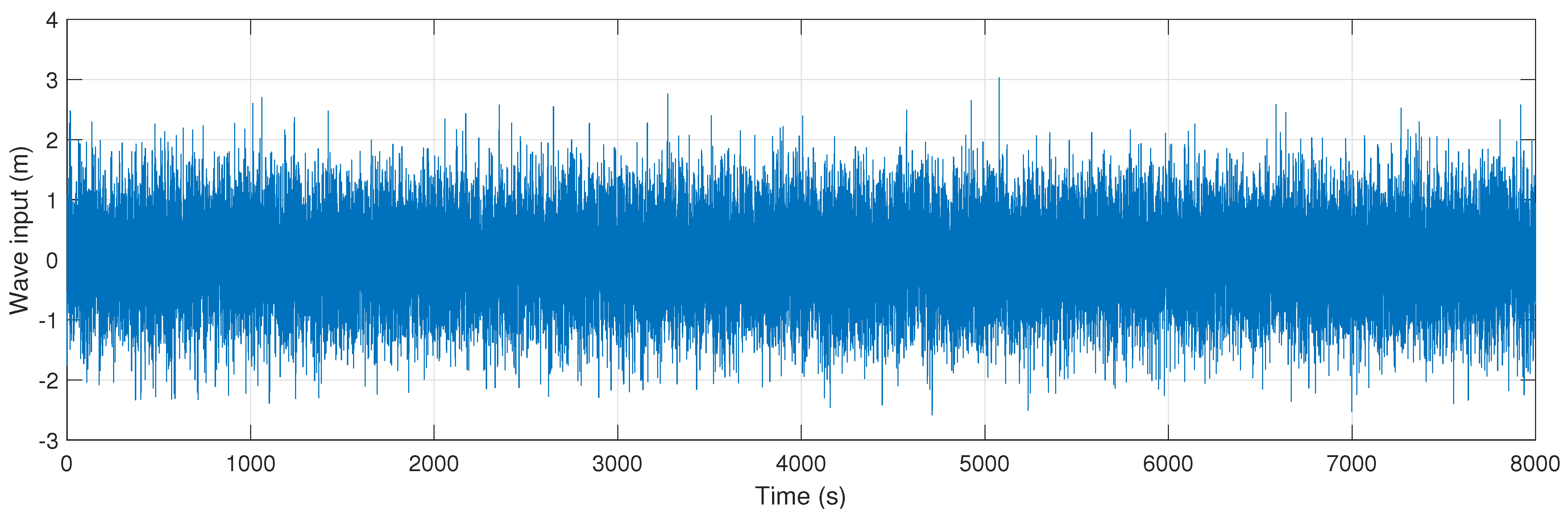
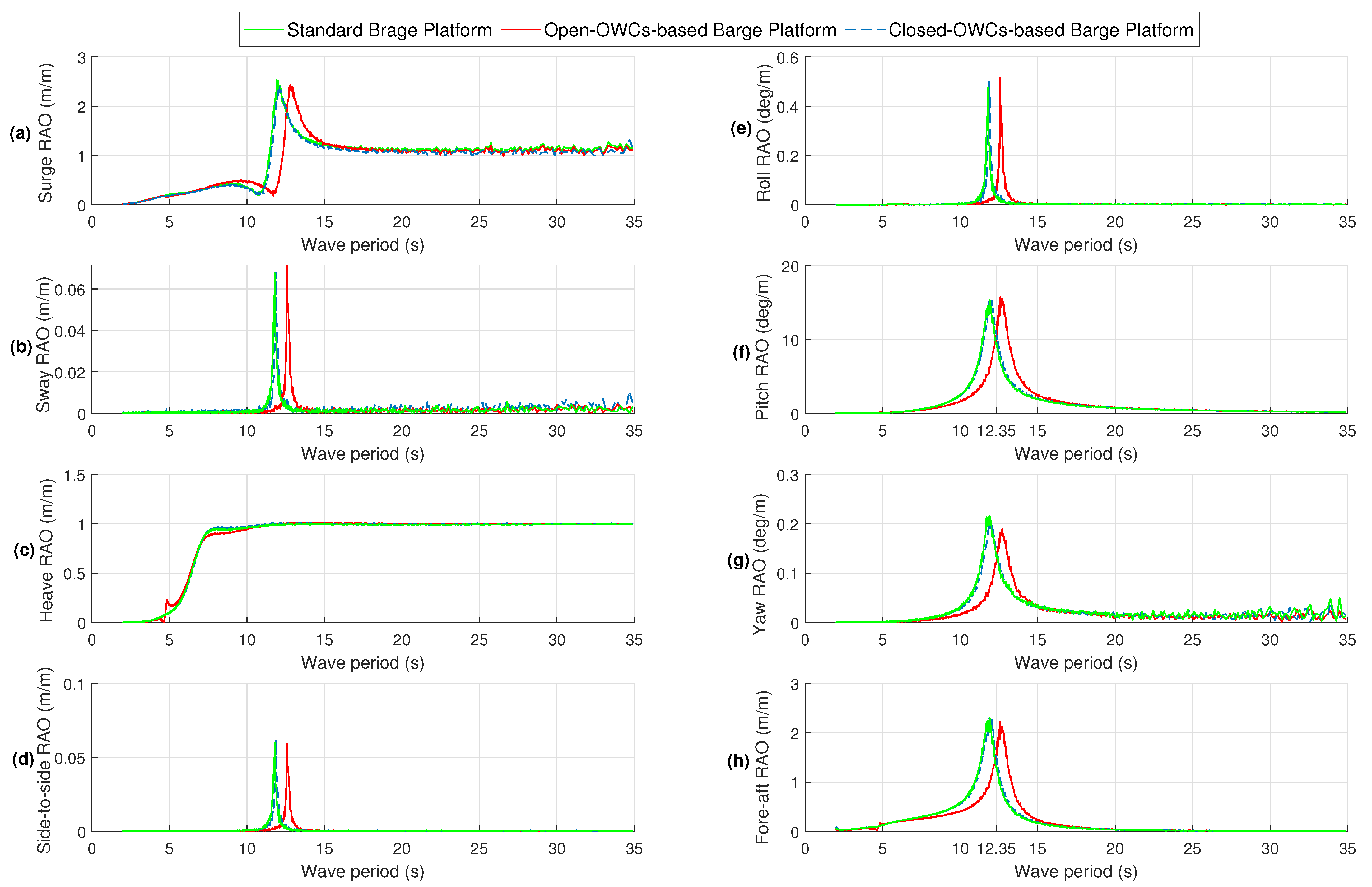
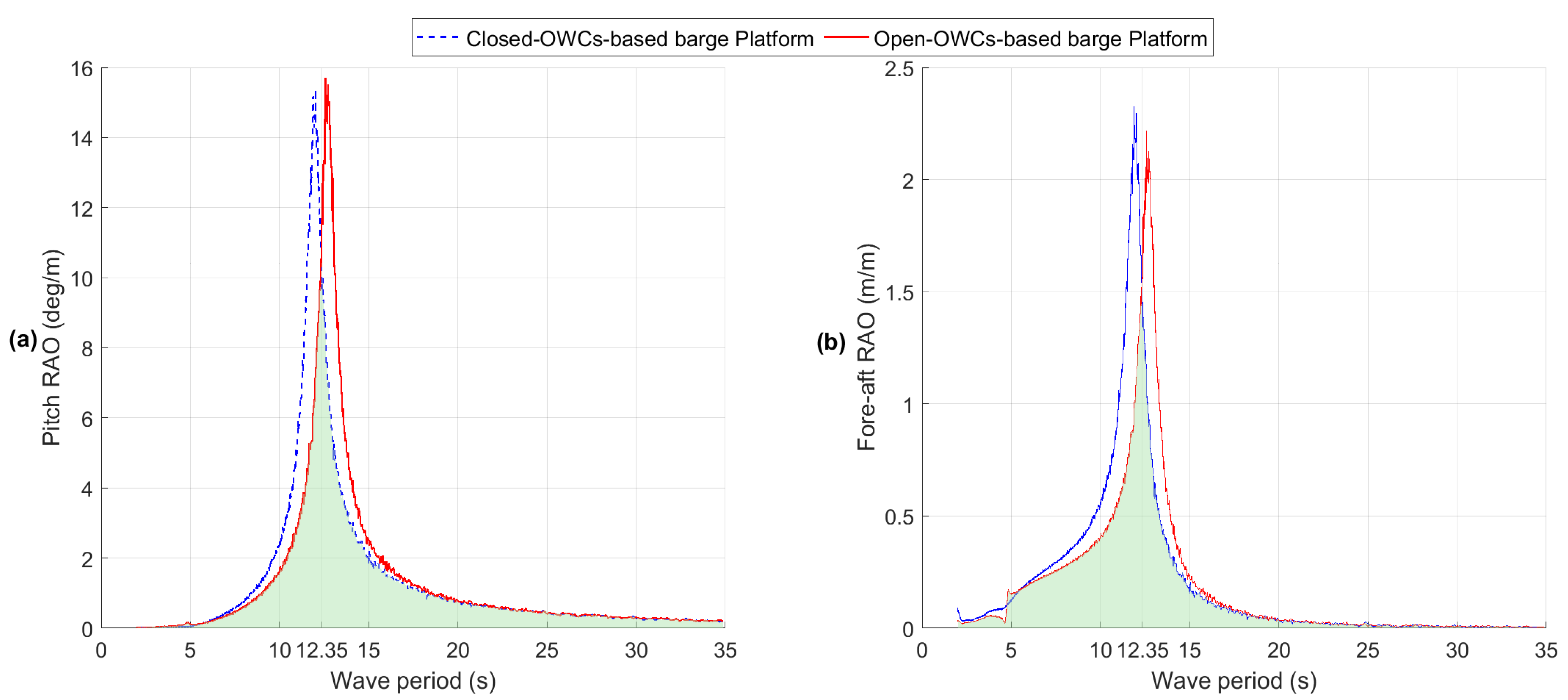
3.1. Barge-Based FOWTs’ Motions Analysis by Response Amplitude Operators

Utilization of RAOs for the evaluation of the FOWTs’ motion in various sea states is crucial. Researchers have used RAOs in different applications for motion evaluation of marine systems. For instance, C. Perez-Collazo et al. in [29] applied RAOs to evaluate a hybrid wind-wave energy converter and G.K.V. Ramachandran et al. in [30] obtained RAOs to analyze the dynamic response of OC3-Hywind spar buoy. In this section, the procedure of plotting the RAOs for different modes of the input-output system is explained. The procedure of obtaining RAOs in frequency-domain for translational and rotational states of the system is as follows. First, geometric data of the standard barge platform, open-OWCs-based barge platform and closed-OWCs-based barge platform has been employed in order to conduct advanced WAMIT calculations to present added-mass, damping, hydrostatics and hydrodynamic matrices. The obtained matrices have been introduced to nonlinear equations of motions with the aim of achieving system’s outputs. RAOs of each mode of the system have been calculated by the auto-spectral density of the input (wave elevation) and the cross-spectral density of the input/output (system responses) with this equation [30]:
R A O = S x y ( ω ) S x x ( ω )
where S x y ( ω ) and S x x ( ω ) are the cross-spectral and auto-spectral densities of the input x ( t ) and the output y ( t ) , in the frequency domain, respectively. S x y ( ω ) and S x x ( ω ) is expressed by:
S x y ( ω ) = 1 M s = 1 M Y [ s ] ( r ) X ¯ [ s ] ( r )
S x x ( ω ) = 1 M s = 1 M X [ s ] ( r ) X ¯ [ s ] ( r )
here X [ s ] is the Fast Fourier Transform (FFT) spectrum of segment s. M is the number of simulations of the procedure and r is the random noise sequence. X ¯ is the complex conjugate of X.
In this research, the procedure has been done for six times ( M = 6 ). Also, white-noise wave inputs with six different seeds have been produced. As it can be seen in Figure 3, the wave input as white-noise is plotted for 8000 s. To ensure that the transient effects have not been considered, 2000 s were removed. Besides, the considered wave input amplitude is one meter to guarantee the linear wave theory. In the end, the average sets are calculated to smooth the spectrum.Also, this averaging the peaks and drops vanish, lets the histogram be concentrated nearby its mean value and decreases the leakage effects with a lower noise sensitivity [31].
Heading waves direction of zero degree with still air is two environmental conditions that have been taken into account. Besides, nonlinearities because of the flexible tower, hydrodynamic loads, viscous effect and mooring lines have been considered.
In this work, RAOs of eight states of the system consisting of surge, sway, heave, side-to-side, roll, pitch, yaw and fore-aft are performed, shown in Figure 4a–h. The period range of RAOs are between 2 s and 35 s. In Figure 4, there have been shown three curves in green, red and blue dash representing for standard barge platform, open-OWCs-based barge platform and closed-OWCs-based barge platform, respectively. An important point realized from the figure, as could be expected, is that the RAOs’ curves for the standard barge platform and closed-OWCs-based barge platform are almost identical. It means that the behaviour of the standard barge and closed-OWCs-based barge platforms are the same in different modes.
Figure 4a shows the surge RAO. It is noticeable that the surge RAOs in three platforms for period ranges of 2–7.5 s and 15–35 s are the same. It is interpreted that all platforms have the same behaviour in surge for those period ranges. There are the surge resonance frequencies at 11.9 s, 12.12 s and 12.8 s for standard barge, closed-OWCs-based barge and open-OWCs-based barge platforms, respectively.
As environmental conditions, it is assumed that the wave direction is zero degree and the air is still. Hence, it is expected that the states excited along sway direction have very slight oscillations. This fact can be proven in Figure 4b,d,e,g representing the sway, side-to-side, roll and yaw RAOs, respectively.
With analyzing the heave RAO shown in Figure 4c, it is noticeable that three platforms have almost the same RAO curves. It means that three platforms almost oscillate similarly in heave. Additionally, after the period of 11.5 s for long-wave periods, the heave RAOs curves are close to 1 m/m which means that the platforms’ heave follows the wave input oscillation.
In this article, analysis of two figures are very important, represented in Figure 4f,h. Analysing of the Pitch RAO (PRAO) and Fore-aft RAO (FRAO) in the figures gives the idea of proposed control strategy in Section 3.2. The PRAO and FRAO curves for standard barge and closed-OWCs-based platforms are almost identical with very small differences. Also, in the figures, when there is a higher RAO, oscillation in that mode is more. It is noticeable in Figure 4f that PRAOs increase to reach the natural periods at 11.9 s, 12.02 s and 12.58 s for the standard barge, open-OWCs-based barge and closed-OWCs-based barge platforms, respectively. After that natural period, the platforms’ PRAO declines to reach near zero. It is observable that for the period ranges of 2–12.25 s and 2–12.35 s, the open-OWCs-based barge platform’s PRAO is considerably less than that of the standard barge and the closed-OWCs-based barge platforms, respectively. Also, for the periods longer than 12.25 s and 12.35 s, the standard barge and closed-OWCs-based barge platforms’ PRAOs respectively less than the PRAO for the open-OWCs-based barge platform.
The FRAOs for the platforms have the same behaviour as the PRAOs. It may be noticed in Figure 4h that the FRAOs increases to reach its natural periods at 11.79 s, 11.88 s and 12.58 s for the standard barge, open-OWCs-based barge and closed-OWCs-based barge platforms, respectively. After that platforms’ FRAO declines to reach near zero. Like the PRAOs, the FRAO for the open-OWCs-based barge platform is lower than the standard barge and closed-OWCs-based barge platforms for the periods shorter than 12.25 s and 12.35 s respectively. Besides, for the periods of longer than 12.25 s and 12.35 s, the open-OWCs-based barge platform’s FRAO is higher than the standard barge and closed-OWCs-based barge platforms’ FRAOs, respectively.

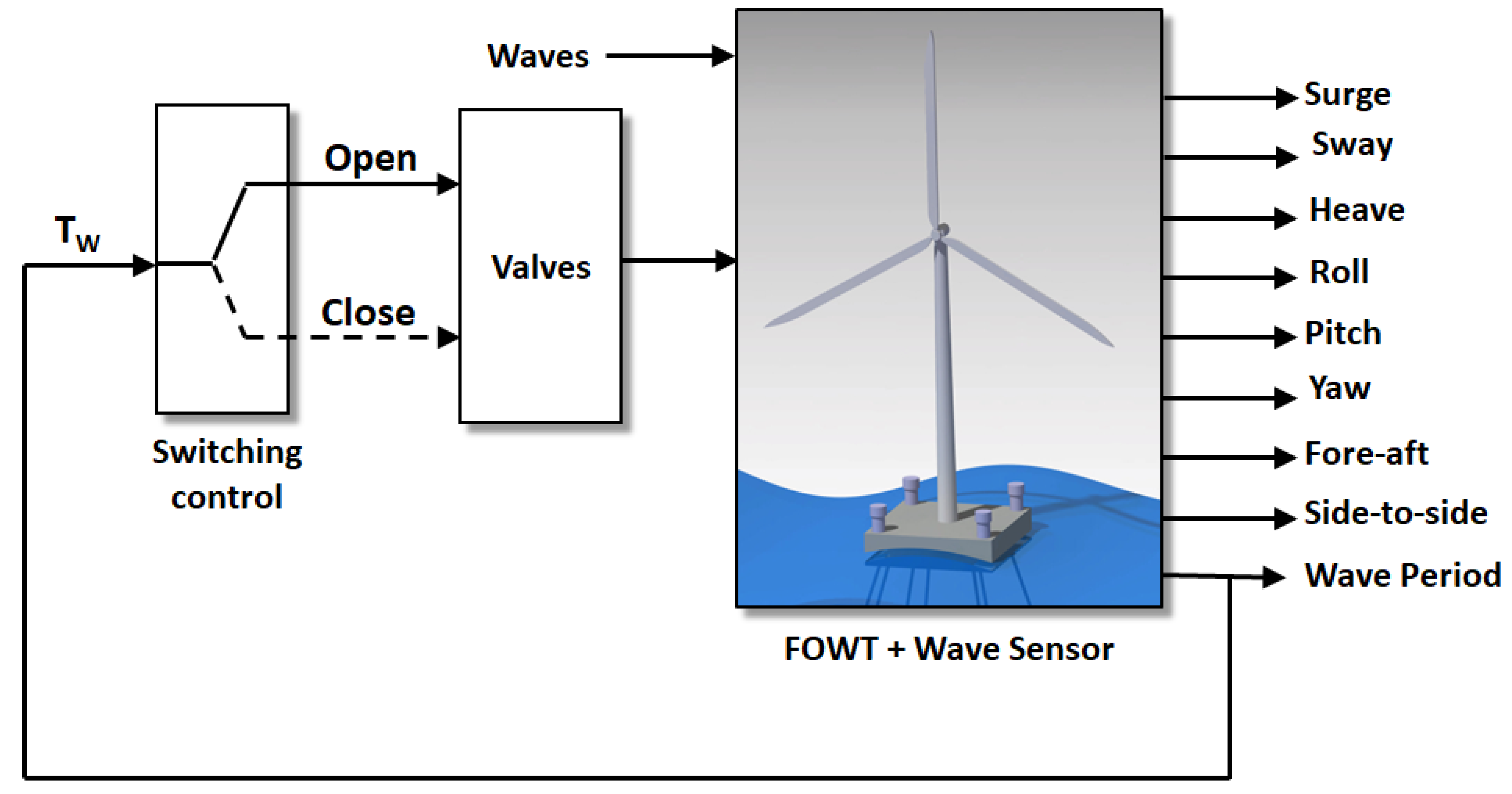
3.2. Control Statement

In this part, a switching control strategy is proposed in order to have a system with lower oscillations, particularly in the pitch and fore-aft motions. In the previous subsection, three platforms’ performance under different sea states have been evaluated. Among different modes with consideration of the environmental condition described in the last section, the PRAO and FRAO have been selected for more detailed evaluations in this section.
In the Section 3.1, it was illustrated that the standard barge and closed-OWCs-based barge platforms’ RAOs have almost identical curves with slight differences. It proves that the behaviour of the platforms are the same for different modes.
Figure 5a,b show the PRAO and FRAO for the closed-OWCs-based barge and open-OWCs-based barge platforms in blue dash and red, respectively.
The closed-OWCs-based barge platform represents a barge platform equipped by four OWCs when the valves are closed, while the open-OWCs-based barge platform represents a barge platform housing four OWCs when the valves are open. It can be seen in Figure 5a,b that the PRAO and FRAO for the open-OWCs-based barge platform have lower values compared to the open-OWCs-based barge platform when the wave period is shorter than 12.35 s. On the other hand, for the wave periods longer than 12.35 s, the PRAO and FRAO for the closed-OWCs-based barge platform are higher than those of for the open-OWCs-based barge platform. It means that for the wave periods shorter than 12.35 s, the open-OWCs-based barge platform has less oscillation (better performance) than the closed-OWCs-based barge platform. Also for the wave periods longer than 12.35 s, the closed-OWCs-based barge platform has less oscillation (better performance) than the open-OWCs-based barge platform. Hence, the green regions in Figure 5a,b represent the optimal operating regions with better performance.
The performance analysis of the platforms in Figure 5 gives the idea of the control strategy for reducing oscillations in the system. Block diagram of the controlled FOWT is represented in Figure 6. In this control system, there are the FOWT with a sensor attached to the bottom of the platform for measuring the wave periods. The measured values of the sensor goes to the switching control. The switching control commands the system to open the valves when the wave periods are shorter than 12.35 s. On Also, the valves are commanded to be closed when the measured wave periods are longer than 12.35 s. This control strategy gives this ability to the system to have the optimal performance in the green regions.
The sensor used in the control system for measuring the wave periods can be an Acoustic Doppler Current Profiler (ADCP) which is a device to measure the water speed transferring through the whole water column [32]. An ADCP attached to the seabed may measure current velocity at the bottom as well as equal intervals all the way up to the surface. In very deep areas, they can be lowered on a cable from the surface. In our case, the ADCP is mounted at the bottom of the barge platform facing downwards, similar to those mounted into ships.
By Doppler effect phenomena, water currents can be measured by the ADCP with sound by means of a principle of sound waves. Pings of sound are sent at a constant frequency to the water and then they are rebounded off the particles suspended in the moving water and reflected to the device. Because of the Doppler effect, there is a slight deference in frequency between the waves that the profiler transmits and the waves it receives which is known as Doppler shift. Using this shift, the device calculates the velocity of the particle and the water around it.

4. Results and Discussion

In this section, the performance of the Controlled 4OWC-based barge platform is compared with the uncontrolled standard barge platform. As it was explained in Section 3.2, in the switching control strategy, the OWCs’ valves are open when the wave periods are shorter than 12.35 s, while the control switching commands to close the OWCs’ valves for the wave periods longer than 12.35 s. In this control strategy, the green regions shown in Figure 5 are the optimal operating regions. The environmental conditions of zero degree wave direction and still air have been considered for the simulations.
To show the capability of the control system for stabilization in time-time, two wave periods have been selected from shorter and longer periods than 12.35 s. In the considered scenario, the controlled 4OWC-based barge and standard barge platforms are studied by two sea state conditions. The wave period of 10 s starting from 0–100 s with a 0.9 s amplitude and the wave period of 14 s starting from 100–240 s with the amplitude 0.9 s have been considered as shown in Figure 7.
Due to the very low RAOs ’curves for sway, side-to-side, roll and yaw in Figure 4b,d,e,g, it is expected to see very small oscillations for both the standard barge and controlled 4OWC-based barge platforms under different sea states. This aspect can be seen in Figure 8b, Figure 9a,c and Figure 10b for sway, roll, yaw and side-to-side motions where slight vibrations are observable. From Figure 4a, it is expected to observe the same oscillations in Surge in time-domain for periods of 10 s and 14 s for both controlled barge and standard barge platforms, shown in Figure 8a.
In Figure 4c represented for the heave RAO, It may be observed that the controlled barge platform has lower oscillations in the wave period of 10 s from 0 s to 100 s, shown in Figure 8c. After switching to the wave period of 14 s at 100 s, the oscillations of the controlled barge and standard barge platforms in have are almost the same by consideration of Figure 4c and Figure 8c.
Note that the aim of the the controlled barge platform is to reduce the oscillations in pitch and fore-aft motions under the considered environmental conditions.
As it can be seen in Figure 4f and Figure 5a, the PRAO for the open-OWCs-based barge platform is lower than that of the standard barge platform for the period of 10 s. At this period, the controller open all the valves in the platform so that the platform acts like the open-OWCs-based barge platform. Hence in time-domain shown in Figure 9b, the oscillations in Pitch declined by 30.8% from 4.106 degree for the standard barge platform to 2.841 degree for the controlled 4OWC-based barge platform.
On the other hand with consideration of Figure 4f and Figure 5a, for the wave period of 14 s, the PRAOs for the closed-OWCs-based barge platform is lower than the open-OWCs-based barge platform. Hence, after 100 s when the wave period changes to 14 s in Figure 9b, the controller closes all the valves so that the platform acts like the closed-OWCs-based barge platform. In the figure, the oscillations of the standard barge and closed-OWCs-based barge platforms are almost the same. It was expected from the PRAOs that pitch of the mentioned platforms are almost identical for all the frequencies.
For the period of 10 s, the FRAOs in Figure 4h and Figure 5b for the open-OWCs-based barge platform is less than that of for standard barge platform. It means that it is expected to see less oscillations in fore-aft for the open-OWCs-based barge platform, compared to standard barge platform. In Figure 10a starting from 0 s to 100 s with the wave period 10 s, the controller opens all the valves so that the platform acts like the open-OWCs-based barge platform. As a result as shown in the figure, the for-aft oscillations decreased by 25% from 0.9241 m for the standard barge platform to 0.69 m for the controlled 4OWC-based barge platform. However, as it is expected from the FRAOs in Figure 4f and Figure 5a for the period of 14 s, the FRAOs’ curves for the closed-OWCs-based barge and standard barge platforms are lower than the open-OWCs-based barge platform. In Figure 10a after 100 s, the wave period is 14 s and the controller switches in order to close all the valves. In this case, the platform acts like the closed-OWCs-based barge platform. It is observable in the figure that the oscillations of the standard barge and closed-OWCs-based barge platforms are almost the same with very slight difference.

5. Conclusions

In this article, a switching control method was proposed in order to decrease the oscillations of the FOWT in the systems’ modes, particularly pitch and top tower fore-aft motions. In order to achieve this goal, the FOWTs motions in different modes were evaluated using RAOs in frequency domain. Through the RAOs’ analysis, a new method was proposed for closing/opening the valves of the OWCs housing in the platform. By RAOs, It was observable that for the shorter wave periods (<12.35 s) the open-OWCs-based barge platform has better performance, hence the controller opens the OWCs’ valves. On the other hand, for the longer wave periods (>12.35 s), the performance of the the oscillations of the standard barge and closed-OWCs-based barge platforms are better than the open-OWCs-based barge platform. As a result, the controller closes the OWCs’ valves in order to effectively reduce the oscillations in pitch and top tower fore-aft motions. In order to measure the incident wave characteristics, an ADCP mounted at the bottom of the barge platform has been considered.
To show the performance of the proposed control method, a representative scenario was considered as follows; the wave period of 10 s starting from 0–100 s changes to the wave period of 14 s starting from 100–240 s. The results showed that with the wave input period 10 s, the pitch and top tower fore-aft oscillations decreased drastically for the controlled 4OWC-based barge platform, compared to the standard barge platform. Hence, it has been shown that the proposed control strategy improves the system’s performance by reducing undesired oscillations that arise at specific frequencies when compared with the standard uncontrolled barge platform.

Author Contributions

Conceptualization, P.A., F.M., I.M., I.G. and A.J.G.; Formal analysis, P.A., F.M., I.M., I.G. and A.J.G.; Investigation, P.A., F.M., I.M., I.G. and A.J.G.; Methodology, P.A., F.M., I.M., I.G. and A.J.G.; Supervision, F.M., I.M., I.G. and A.J.G.; Validation, P.A., F.M., I.M., I.G. and A.J.G.; Visualization, P.A., F.M., I.M., I.G. and A.J.G.; Writing—original draft, P.A., F.M., I.M., I.G. and A.J.G.; Writing—review & editing, P.A., F.M., I.M., I.G. and A.J.G. All authors have read and agreed to the published version of the manuscript.

Funding

This work was supported in part by the Basque Government, through project IT1207-19 and by the MCIU/MINECO through the projects RTI2018-094902-B-C21 and RTI2018-094902-B-C22 (MCIU/AEI/FEDER, UE).

Institutional Review Board Statement

Not applicable.

Informed Consent Statement

Not applicable.

Data Availability Statement

Not applicable.

Conflicts of Interest

The authors declare no conflict of interest.

Abbreviations

The following abbreviations are used in this manuscript:
DOFDegree Of Freedom
FASTFatigue, Aerodynamics, Structures and Turbulence
FFTFast Fourier Transfer
FOWTFloating Offshore Wind Turbine
RAOResponse Amplitude Operator
FRAOFore-aft Response Amplitude Operator
PRAOPitch Response Amplitude Operator
OWCOscillating Water Column
PTOPower Take Off
SWLStill Water Level
TMDTuned Mass Damper
WECWave Energy Converter

References

  1. Sher, F.; Curnick, O.; Azizan, M.T. Sustainable Conversion of Renewable Energy Sources. Sustainability 2021, 13, 2940. [Google Scholar] [CrossRef]
  2. Elusakin, T.; Shafiee, M.; Adedipe, T.; Dinmohammadi, F. A Stochastic Petri Net Model for O&M Planning of Floating Offshore Wind Turbines. Energies 2021, 14, 1134. [Google Scholar]
  3. Suzuki, H.; Sakai, Y.; Yoshimura, Y.; Houtani, H.; Carmo, L.H.; Yoshimoto, H.; Kamizawa, K.; Gonçalves, R.T. Non-Linear Motion Characteristics of a Shallow Draft Cylindrical Barge Type Floater for a FOWT in Waves. J. Mar. Sci. Eng. 2021, 9, 56. [Google Scholar] [CrossRef]
  4. Cottura, L.; Caradonna, R.; Ghigo, A.; Novo, R.; Bracco, G.; Mattiazzo, G. Dynamic modeling of an offshore floating wind turbine for application in the Mediterranean Sea. Appl. Sci. 2021, 14, 248. [Google Scholar]
  5. Benazzouz, A.; Mabchour, H.; El Had, K.; Zourarah, B.; Mordane, S. Offshore Wind Energy Resource in the Kingdom of Morocco: Assessment of the Seasonal Potential Variability Based on Satellite Data. J. Mar. Sci. Eng. 2021, 9, 31. [Google Scholar] [CrossRef]
  6. Karimirad, M.; Koushan, K. WindWEC: Combining wind and wave energy inspired by hywind and wavestar. In Proceedings of the 2016 IEEE International Conference on Renewable Energy Research and Applications (ICRERA), Birmingham, UK, 20–23 November 2016; pp. 96–101. [Google Scholar]
  7. Maria-Arenas, A.; Garrido, A.J.; Rusu, E.; Garrido, I. Control strategies applied to wave energy converters: State of the art. Energies 2019, 12, 3115. [Google Scholar] [CrossRef] [Green Version]
  8. Quevedo, E.; Delory, M.; Castro, A.; Llinas, O.; Hernandez, J. Modular multi-purpose offshore platforms, the TROPOS project approach. In Proceedings of the Fourth International Conference on Ocean Energy (ICOE), Dublin, Ireland, 17–19 October 2012; pp. 1–5. [Google Scholar]
  9. Sharay, A.; Iglesias, G. The economics of wave energy: A review. Renew. Sustain. Energy Rev. 2015, 45, 397–408. [Google Scholar]
  10. Lackner, M.A. An investigation of variable power collective pitch control for load mitigation of floating offshore wind turbines. Wind Energy 2013, 16, 435–444. [Google Scholar] [CrossRef]
  11. Matha, D. Model Development and Loads Analysis of an Offshore Wind Turbine on a Tension Leg Platform with a Comparison to Other Floating Turbine Concepts (No. NREL/SR-500-45891); National Renewable Energy Lab. (NREL): Golden, CO, USA, 2009. [Google Scholar]
  12. Haji, M.N.; Kluger, J.M.; Sapsis, T.P.; Slocum, A.H. A symbiotic approach to the design of offshore wind turbines with other energy harvesting systems. Ocean Eng. 2018, 169, 673–681. [Google Scholar] [CrossRef]
  13. Slocum, A.; Kluger, J.; Mannai, S. Energy Harvesting and Storage System Stabilized Offshore Wind Turbines. In Proceedings of the 2019 Offshore Energy and Storage Summit (OSES), Brest, France, 10–12 July 2019; pp. 1–6. [Google Scholar]
  14. Yang, W.; Tian, W.; Hvalbye, O.; Peng, Z.; Wei, K.; Tian, X. Experimental research for stabilizing offshore floating wind turbines. Energies 2019, 12, 1947. [Google Scholar] [CrossRef] [Green Version]
  15. Kamarlouei, M.; Gaspar, J.F.; Calvario, M.; Hallak, T.S.; Mendes, M.J.; Thiebaut, F.; Soares, C.G. Experimental analysis of wave energy converters concentrically attached on a floating offshore platform. Renew. Energy 2020, 152, 1171–1185. [Google Scholar] [CrossRef] [Green Version]
  16. Zhang, Y.; Zhao, X.; Wei, X. Robust structural control of an underactuated floating wind turbine. Wind Energy 2020, 23, 2166–2185. [Google Scholar] [CrossRef]
  17. Hu, Y.; Wang, J.; Chen, M.Z.; Li, Z.; Sun, Y. Load mitigation for a barge-type floating offshore wind turbine via inerter-based passive structural control. Eng. Struct. 2018, 177, 198–209. [Google Scholar] [CrossRef]
  18. Wei, X.; Zhao, X. Vibration suppression of a floating hydrostatic wind turbine model using bidirectional tuned liquid column mass damper. Wind Energy 2020, 23, 1887–1904. [Google Scholar] [CrossRef]
  19. Sarmiento, J.; Iturrioz, A.; Ayllón, V.; Guanche, R.; Losada, I.J. Experimental modelling of a multi-use floating platform for wave and wind energy harvesting. Ocean Eng. 2019, 173, 761–773. [Google Scholar] [CrossRef]
  20. Cooper, M.; Heidlauf, P.; Sands, T. Controlling Chaos—Forced van der Pol Equation. Mathematics 2017, 5, 70. [Google Scholar] [CrossRef] [Green Version]
  21. Jonkman, J.M. Dynamics Modeling and Loads Analysis of an Offshore Floating Wind Turbine (No. NREL/TP-500-41958); National Renewable Energy Lab. (NREL): Golden, CO, USA, 2007. [Google Scholar]
  22. Aboutalebi, P.; M’zoughi, F.; Garrido, I.; Garrido, A.J. Performance Analysis on the Use of Oscillating Water Column in Barge-Based Floating Offshore Wind Turbines. Mathematics 2021, 9, 475. [Google Scholar] [CrossRef]
  23. Jonkman, J.; Butterfield, S.; Musial, W.; Scott, G. Definition of a 5-MW Reference Wind Turbine for Offshore System Development (No. NREL/TP-500-38060); National Renewable Energy Lab. (NREL): Golden, CO, USA, 2009. [Google Scholar]
  24. Aboutalebi, P.; Garrido, A.J.; M’zoughi, F.; Garrido, I. Stabilization of a Floating Offshore Wind Turbine Using Oscillating Water Columns. In Proceedings of the 2nd Workshop on Wind and Marine Energy (WWME), Online, 17 December 2020. [Google Scholar]
  25. Amundarain, M.; Alberdi, M.; Garrido, A.J.; Garrido, I. Neural rotational speed control for wave energy converters. Int. J. Control 2011, 84, 293–309. [Google Scholar] [CrossRef]
  26. M’zoughi, F.; Garrido, I.; Bouallègue, S.; Ayadi, M.; Garrido, A.J. Intelligent Airflow Controls for a Stalling-Free Operation of an Oscillating Water Column-Based Wave Power Generation Plant. Electronics 2019, 8, 70. [Google Scholar] [CrossRef] [Green Version]
  27. M’zoughi, F.; Garrido, I.; Garrido, A.J.; De La Sen, M. Self-adaptive global-best harmony search algorithm-based airflow control of a wells-turbine-based oscillating-water column. Appl. Sci. 2020, 10, 4628. [Google Scholar] [CrossRef]
  28. Aubault, A.; Alves, M.; Sarmento, A.N.; Roddier, D.; Peiffer, A. Modeling of an oscillating water column on the floating foundation WindFloat. In Proceedings of the International Conference on Offshore Mechanics and Arctic Engineering, Rotterdam, The Netherlands, 19–24 June 2011; pp. 235–246. [Google Scholar]
  29. Perez-Collazo, C.; Greaves, D.; Iglesias, G. Hydrodynamic response of the WEC sub-system of a novel hybrid wind-wave energy converter. Energy Convers. Manag. 2018, 171, 307–325. [Google Scholar] [CrossRef]
  30. Ramachandran, G.K.V.; Robertson, A.; Jonkman, J.M.; Masciola, M.D. Investigation of Response Amplitude Operators for Floating Offshore Wind Turbines (No. NREL/CP-5000-58098); National Renewable Energy Lab. (NREL): Golden, CO, USA, 2013. [Google Scholar]
  31. Pintelon, R.; Schoukens, J. System Identification: A Frequency Domain Approach; John Wiley & Sons: Hoboken, NJ, USA, 2012; pp. 54–64. [Google Scholar]
  32. M’zoughi, F.; Garrido, I.; Garrido, A.J.; La Sen, D.; De La, M. ANN-Based Airflow Control for an Oscillating Water Column Using Surface Elevation Measurements. Sensors 2020, 20, 1352. [Google Scholar] [CrossRef] [PubMed] [Green Version]
Figure 1. Barge-based floating offshore wind turbine with four OWCs.
Applsci 11 05249 g001
Figure 2. Platforms’ geometry for (a) Standard barge platform. (b) 4OWC-based barge platform with closed valves. (c) 4OWC-based barge platform with open valves.
Applsci 11 05249 g002
Figure 3. Wave elevation as white noise.
Applsci 11 05249 g003
Figure 4. RAOs for (a) Surge. (b) Sway. (c) Heave. (d) Side-to-side. (e) Roll. (f) Pitch. (g) Yaw. (h) Fore-aft.
Applsci 11 05249 g004
Figure 5. RAOs for (a) Pitch. (b) Fore-aft.
Applsci 11 05249 g005
Figure 6. Block diagram of controlled FOWT.
Applsci 11 05249 g006
Figure 7. Considered wave input to the barge-based platforms.
Applsci 11 05249 g007
Figure 8. Platforms’ translational modes. (a) Surge. (b) Sway. (c) Heave.
Applsci 11 05249 g008
Figure 9. Platforms’ rotational modes. (a) Roll. (b) Pitch. (c) Yaw.
Applsci 11 05249 g009
Figure 10. Top tower displacements. (a) Fore-aft. (b) Side-to-side.
Applsci 11 05249 g010
Table 1. 5-MW floating wind turbine Features [24].
ParameterValue
Hub height90 m
Center of mass location38.23 m
Rotor diameter126 m
Number of blades3
Initial rotational speed12.1 rpm
Blades mass53.22 kg
Nacelle mass240,000 kg
Hub mass56,780 kg
Tower mass347,460 kg
Power output5 MW
Cut-in, Rated, Cut-out wind speed3 m/s, 11.4 m/s, 25 m/s
Table 2. Standard barge and the 4OWC-based barge platforms’ features.
ParameterValue
Platforms’ size (W × L × H)40 m × 40 m × 10 m
Each OWC’s size (W × L × H)5 m × 5 m × 10 m
Draft, Free board for both platforms4 m, 6 m
Water displacement for the simple barge6400 m 3
Water displacement for the barge with OWCs6000 m 3
Mass, Including Ballast5,452,000 kg
CM Location below SWL0.281768 m
Roll Inertia about CM726,900,000 kg·m 2
Pitch Inertia about CM726,900,000 kg·m 2
Yaw Inertia about CM1,453,900,000 kg·m 2
Anchor (Water) Depth150 m
Separation between Opposing Anchors773.8 m
Unstretched Line Length473.3 m
Neutral Line Length Resting on Seabed250 m
Line Diameter0.0809 m
Line Mass Density130.4 kg/m
Line Extensional Stiffness589,000,000 N
Publisher’s Note: MDPI stays neutral with regard to jurisdictional claims in published maps and institutional affiliations.

