Article

A Large-Scale Model of Lateral Pressure on a Buried Pipeline in Medium Dense Sand

by
Hamzh Alarifi
1,*,
Hisham Mohamad
1,
Nor Faridah Nordin
2,
Muhammad Yusoff
1,
Aminu Darda’u Rafindadi
1,3 and
Budijanto Widjaja
4
1
Civil and Environmental Engineering Department, Universiti Teknologi PETRONAS, Bandar Seri Iskandar, Perak 32610, Malaysia
2
Department of Irrigation and Drainage Malaysia, Jalan Sultan Salahuddin, Kuala Lumpur 50626, Malaysia
3
Department of Civil Engineering, Bayero University, Kano P.M.B. 3011, Nigeria
4
Department of Civil Engineering, Universitas Katolik Parahyangan, Bandung 40141, Indonesia
*
Author to whom correspondence should be addressed.
Submission received: 10 March 2021 / Revised: 1 May 2021 / Accepted: 5 May 2021 / Published: 16 June 2021
(This article belongs to the Special Issue Seismic Geotechnical Hazards Studies)

Abstract

:
Modern countries utilise buried pipelines for the long-distance transportation of water, oil, and gas due to their efficiency and continuity of delivery to receiving locations. Due to soil movements such as landslides, excessive earth pressure imposed on buried pipelines causes damage and, consequently, leaking of liquids, gases or other harmful effluents into the soil, groundwater, and atmosphere. By using a large-scale physical model, the lateral pipeline–soil interaction in sandy soil was researched. This study investigated the stress distribution on a buried pipe induced by lateral soil displacement. The external forces on the buried pipe caused by the surrounding soil motion were measured using earth pressure cells installed in the active zone along the pipeline. Additionally, visual inspection of ground deformation patterns on the surface, including tensile cracks, above a shallow-buried pipeline subjected to lateral soil movement was reported. The results revealed that lateral soil movement has a potency effect on buried pipelines. The findings also indicated that the highest stresses occur at the unstable soil boundaries prior to reaching the soil’s peak strength. After observing the soil surface’s rupture, most of the stress increments were concentrated in the middle section of the pipe.

1. Introduction

Networks of pipeline transportation are crucial indicators of economic growth and development in many countries [1]. Modern countries utilise buried pipelines for the long-distance transportation of water, oil, gas, and other liquids due to their efficiency, convenience, and continuity of delivery to receiving sites [2]. However, because of external soil pressure and internal liquid pressure loads, these buried pipes are usually exposed to critical stresses. Numerous pipeline failure incidences resulting from lateral ground forces have been reported worldwide with varying severity, depending on the pipeline utilization. The consequences of pipeline damages include environmental damage, property damage, injuries, and loss of human life [3]. Rapid urbanization in countries like China has led to reports of frequent damage to buried pipelines in the last three decades, attributable to construction activities which had resulted in lateral ground displacement [4]. Ground movement, such as slope instability, was also confirmed to have been the cause of about 13 percent of European gas pipeline incidents between 2004 and 2013 [5]. Additionally, previous seismic events such as the 1999 Izmit and Chi-Chi earthquakes have indicated that the cessation of pipeline operations resulted from landslides, lateral spread, and fault rupture accidents due to significant permanent ground deformation [6].
A pipeline undergoes displacement as lateral forces grow due to ground motions, and according to the soil characteristics, the resistance of the surrounding soil increases steadily [7]. The lateral deformation of pipes occurs when the pipe axis is normal to the direction of soil movement, resulting in strains and stresses on the pipe wall imposed by the output of bending moments and shear forces [8]. Direct forces caused by soil movements correspond directly with the soil pipe’s relative movement and are significant pipeline operational risks [9,10]. Therefore, an accurate estimation of the external forces applied to the pipe due to slope instability is of the utmost importance in the design or evaluation process.
Previous studies on pipe–soil interaction due to lateral earth movements include experimental work to test the response of buried pipes to lateral earth movements [11]. Trautmann and O’Rourke considered the effects of pipe depth, soil density, pipe diameter, and pipe roughness. Their findings showed that vertical equilibrium needs to be considered when estimating the horizontal response of buried pipelines which agreed well with the established force-displacement analytical model (i.e., Rowe and Davis [12]). Trautmann and O’Rourke proposed an uncomplicated design technique to predict pipeline response to lateral ground movements. An embedded pipe may move along a curved path with horizontal, vertical, and longitudinal elements during slope or embankment instability. Prisco and Galli confirmed the coupling effects of vertical and horizontal soil resistance [13].
Numerical studies were also performed to examine the pipe–soil interaction during relative movements of the oblique or three-dimensional pipe-soil [14]. The forces imposed on the buried pipe due to lateral soil movement are similar to the geotechnical engineering problems of retaining walls or horizontally loaded piles and the associated lateral earth pressures. Soil resists lateral penetration of objects by mobilizing its passive pressure, which contrasts with earth pressure at rest (K). Figure 1 presents a schematic of the lateral ground movement on the buried pipe.
However, physical models of the soil–pipeline relationship are usually carried out by pulling or pushing the pipeline horizontally using wires or rigid shafts in a constant direction [16,17,18,19,20,21,22,23,24,25,26]. Disregarding the pipe’s direction of motion can lead to an overestimation of the loads on the pipe that the soil can bear [19]. Alarifi et al., [27,28] developed a small model to study the behavior of a small diameter of a buried pipe under the landslide effect using strain gauge sensors. They succeeded in running the model by pushing the soil forward to the buried pipe rather than pulling the pipe directly.
Due to lateral earth strain, the rise in soil movement, in turn, contributes to increased pipe stresses. As a result, pipe deflects have become widespread and have become a pressing concern for pipe authorities worldwide. In this respect, it is essential to use models that consider the external factors that contribute to pipe stresses as accurately as possible. This study provides a large-scale experimental outcome to test the pressure on buried pipes due to lateral ground movements.

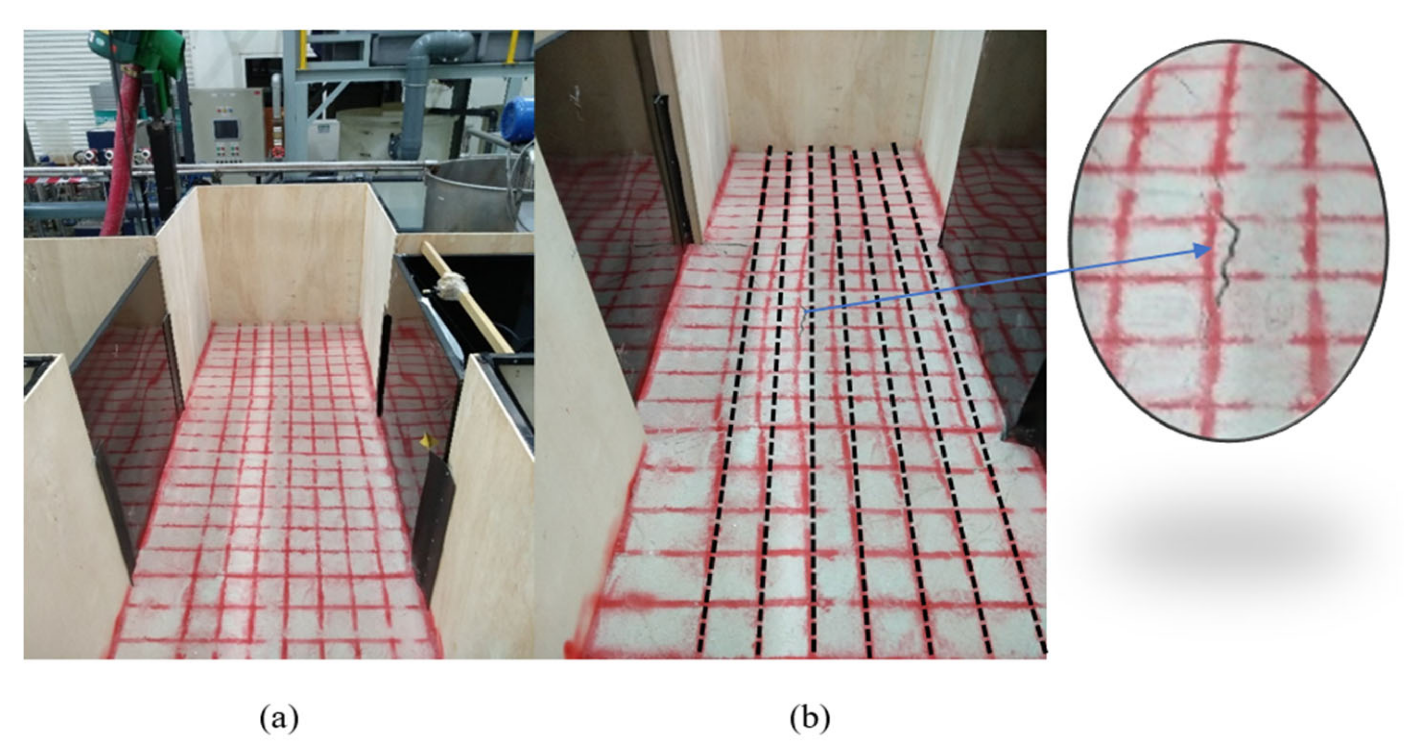
2. Materials and Methods

In this study, a large-scale model was developed to act as the buried pipe under the lateral soil movement effect. Plywood and steel structures were used to fabricate the model of a chamber 3000 mm long, 1000 mm wide, and 1600 mm deep. Movable steel plates with stainless steel roller wheels were placed on a frame of three steel, rounded bars in the middle of the chamber. A High-Density Polyethene pipe (3000 mm long and 90 mm diameter) was installed by simple supports at both ends of the chamber. A manual winch pulley was used to pull the movable plates forward out of the chamber, as shown in Figure 2. Five Earth Pressure Cell sensors (EPCs) of 28 mm diameter and 10 mm thickness were used to measure the pipe pressure developed by soil pressure. A wire displacement sensor with 1000 mm capacity was used to measure the movable plate displacement (soil displacement). Poorly graded sand (Sungai Perak sand) was utilized as the backfill material for this experiment. The materials’ properties are listed in Table 1. A camera was placed adjacent to the model box to capture the digital image of surface deformation of the soil model.
The five earth pressure cell sensors were tested and calibrated by applied known dead loads. The EPCs were placed at different positions on the spring line, one sensor placed in the middle of the pipe where the soil was unstable, two at the boundary of the movable plates, and the other two placed to the left and right of movable plates where the ground was stable, see Figure 3. The EPCs were well attached to the pipe using strong double-sided adhesive tape. The distance between one sensor and another was 500 mm. A flexible conveyor was used to transport the sand from/to the chamber. The chamber was filled with the first layer of backfill material (sand), as the first layer was located on the left and right sides of the movable plates (depth of 170 mm). A manual rammer was used to compact the soil layers to achieve medium density of the backfill (relative density equal between 35% and 65%). The second layer of sand was added (depth of 200 mm) above the movable plate level. The High-Density Polyethylene (HDPE) pipe was placed in the middle of the chamber with the two ends fixed using stainless steel pipe clamps, as shown in Figure 4. The third and fourth layers of the soil were added, with a depth of 90 mm and 160 mm. All the layers were compacted well and tested by the sand replacement method [29] to achieve the medium density of the backfill. The backfill’s top surface was marked with a red square-grid pattern to monitor the surface failure at the end of the experiment. The wire displacement sensor was installed on top of the movable plates and connected to a data logger to automatically record the plate displacement values.
In addition, the EPCs were also connected to the same data logger to record the stress on the buried pipe. The movable plate was pulled out (displacement of 50 mm) using a manual pulley, and the data logger started to record the stress values from the earth pressure sensors. Moving plate displacement increased gradually by 50 mm, from zero to 700 mm, and stress measurements were recorded in real-time at each stage of the movement.

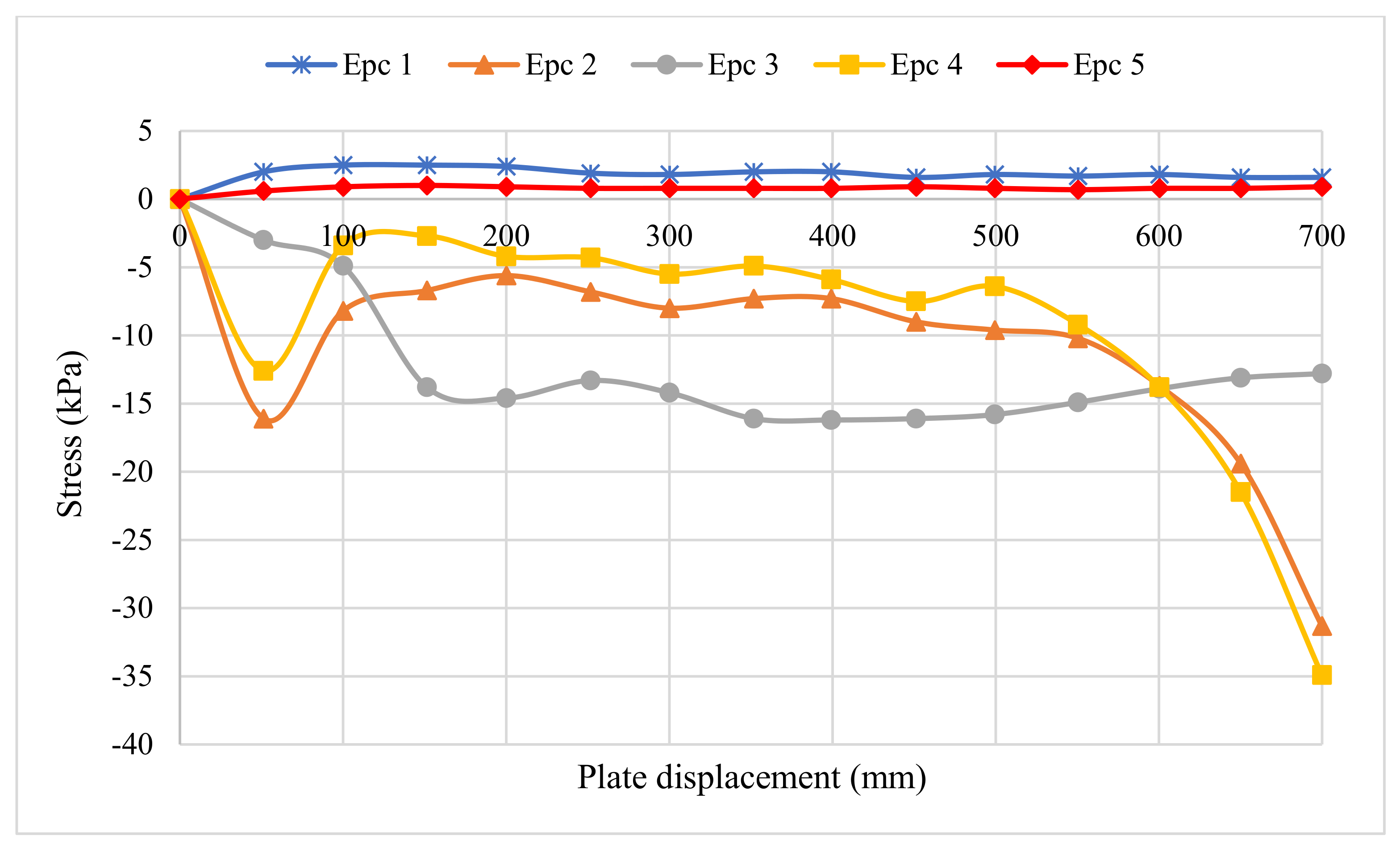
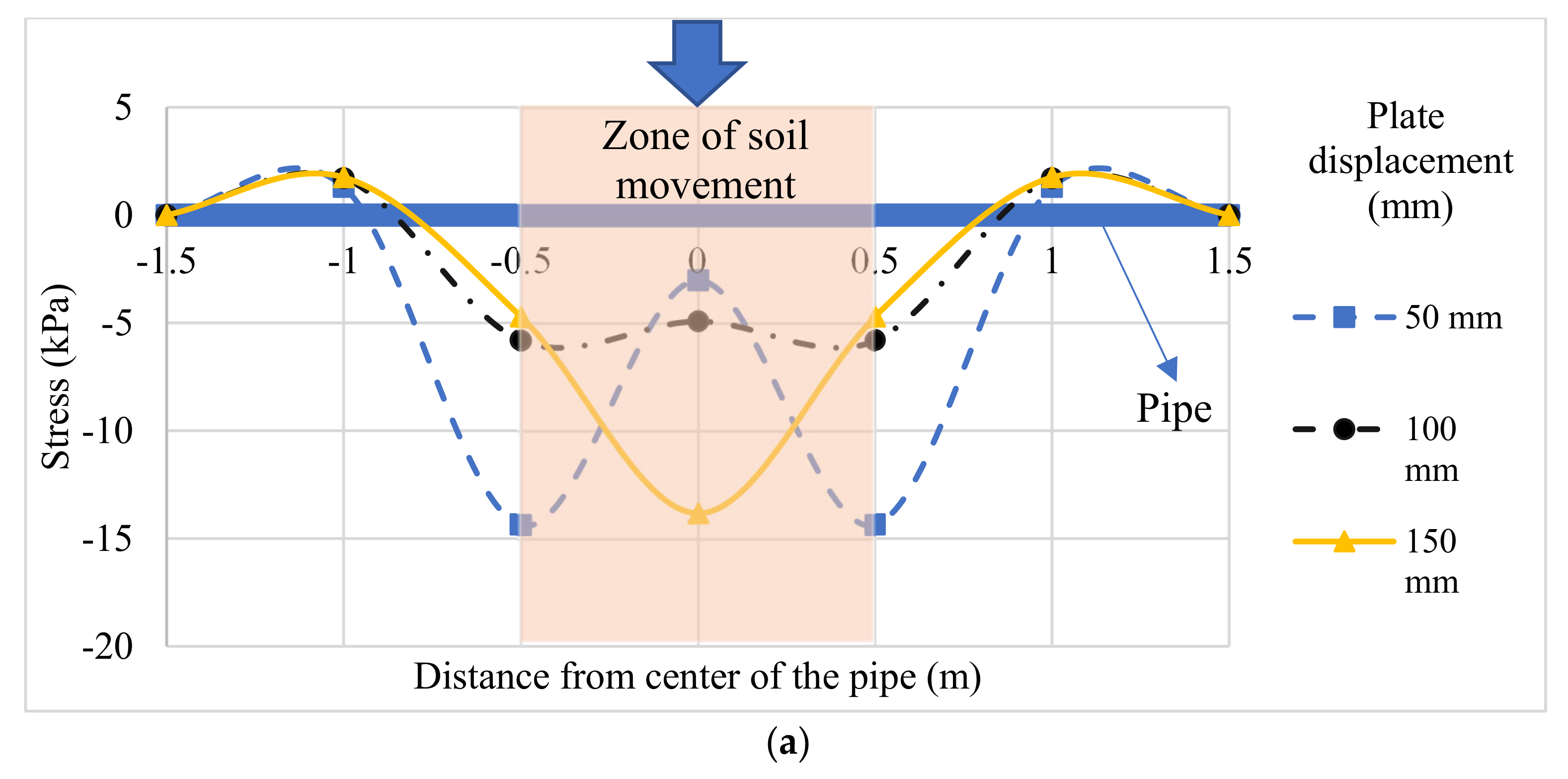
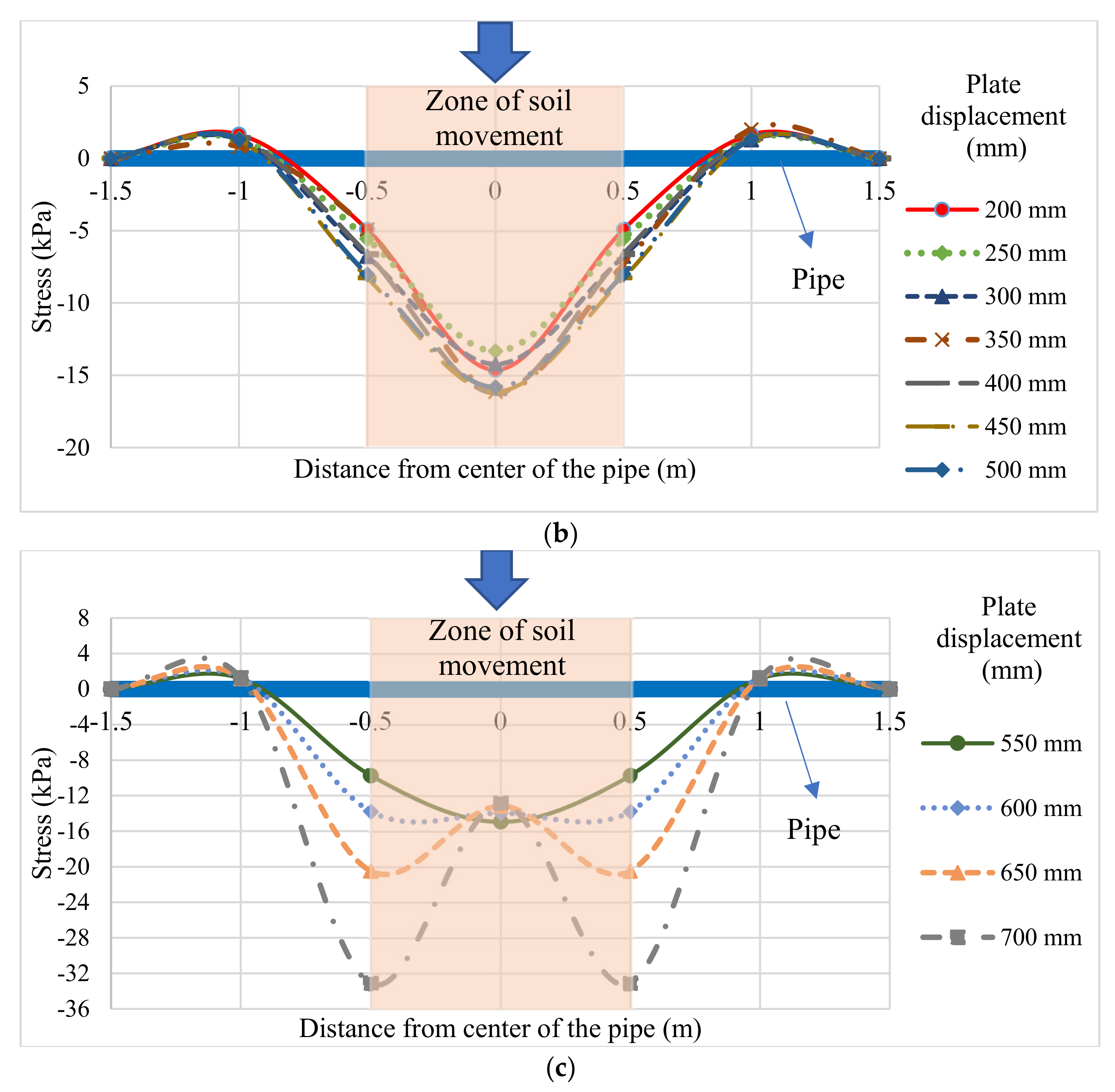
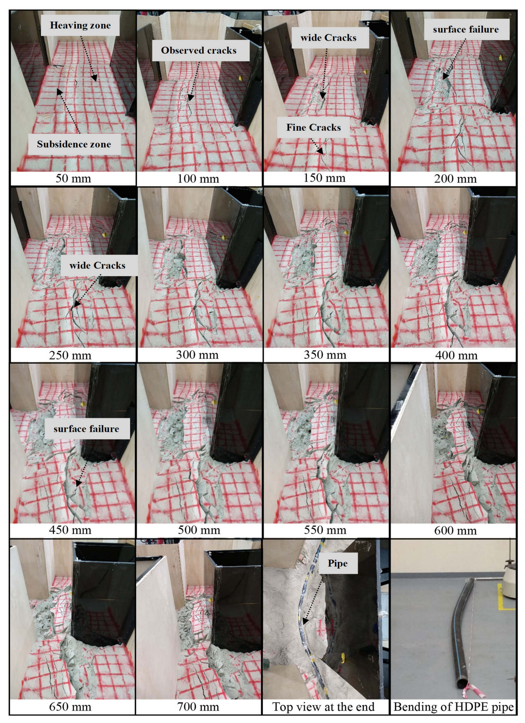
3. Results and Discussion

In this study, a large-scale model, developed to assess the stress on buried pipes due to lateral ground movement, is presented. Earth pressure cell sensors were used to measure the stress along the buried High-Density Poly-Ethylene (HDPE) pipe, which was subjected to lateral ground movement in the large-scale physical model. A strain measurement data logger was used to record the stress values. Figure 5 demonstrates the recorded stress values at various positions on the buried pipe. The movable plate displacements were recorded using a wire displacement sensor. In general, the stress values rose steadily (either positively or negatively) along the buried pipe as the soil displacement increased.
Figure 6a illustrates the behavior of the stresses at the front side of the pipe (EPC 1, 2, 3, 4, and 5) during the initial stages of plate motions that were measured using wire displacement sensors (50 mm, 100 mm, and 150 mm). At 50 mm of plate movement, EPC 2 and EPC 4 (located at the unstable soil boundary) recorded the highest stresses with an average value of −14.35 kPa. The middle section of the pipe (EPC 3) recorded pressure of −3 kPa, whereas in the stable soil zones (EPC 1 and EPC 5) minimum pressures were recorded, i.e., the average pressure was only 1.3 kPa. The negative stress values indicate the active soil pressures at EPC 2, EPC 3, and EPC 4. In contrast, the positive stress values in EPC 1 and EPC 5 indicate that soil pressures on the pipe were in the passive zone. Referring to Figure 5; Figure 6a, the stresses at EPC 2 and EPC 4 started to drop when the displacement of the movable plate had exceeded 50 mm, which indicates the failure of soil at the boundary of the landslide. In contrast, the stress values of EPC 3 began to rise (located at the middle of pipe).
Figure 6b shows stress values at the plate displacement from 200 mm to 500 mm with no significant stress changes. The soil pressure began to increase again in small amounts at the boundary of the landslide. In contrast, at the middle of the pipe, the soil pressures were not constant (increases and decreases in an unregulated manner). At 550 mm of plate movement, the stresses at the boundary of the landslide began to increase because the wall was approaching closer to the pipe (see Figure 6c). In comparison, the pressures in the mid-section began to decrease due to the soil failure in the middle of the landslide area.
According to the analysis of lateral soil pressure on the pipeline, the section of the buried pipeline located in the landslide area experienced the greatest stress [30]. The lateral pressure increased as soil displacement increased, and soil surface deformations appeared above the pipe position [9]. In this experiment, a camera was mounted next to the model box to monitor the soil surface deformations. The evolution process of soil instability and failure was recorded in real-time by the camera. Figure 7 illustrates the surface displacement of the soil before and after moving the movable plate. Figure 7a displays the soil surface position before starting the experiment, while Figure 7b presents the surface of the soil after displacing the moving plate by 50 mm. The dashed black lines represent the original location of the ground before the displacement.
Some initial cracks appeared on the surface of the soil due to the accidental movement of the ground. Most of the cracks at 50 mm were superficial as marked by the brown arrows, and these cracks represent the boundaries of subsidence and heaving of the soil zones (see Figure 8). When the movable plate reached 100 mm, tension cracks appeared in the unstable zone and behind the buried pipe due to increased stress on the pipe. The cracks extended to the stable area (left and right sides) when the plate exceeded 150 mm of movement. The soil surface cracks expanded and widened as the movable plate’s movement increased (see Figure 8, from 200 mm to 700 mm), and these cracks appeared (in both horizontal and vertical directions). Moreover, due to continuing lateral soil displacement towards the buried pipe, numerous cracks were formed along the landslide’s perpendicular direction. After removing the top layer of the backfill at the end of the experiment, the HDPE pipe was in a bent position due to the large lateral soil displacement produced during the test [9].

4. Conclusions

This research simulated the lateral earth pressure on an HDPE buried pipe induced by a landslide. It also investigated the stresses along the buried pipe and observed the surface cracks under the lateral soil displacement effect. The results from the experiment indicated that the highest earth pressures occurred at the unstable soil boundaries upon reaching the soil strength at failure. The section of the buried pipeline located in the landslide area experienced the greatest stress [30]. Generally, lateral earth pressure rose steadily along the buried pipe as the ground was being mobilized. It was discovered that there was a strong relationship between lateral pressures on the buried pipe and soil surface deformation. Some of the findings provided from this research can be generally applicable for cases related to HDPE water mains backfilled with sands. Understanding the active and passive pressures surrounding the pipeline during landslides is important for the subsequent assessment of pipeline deformation and risk models. The authors intend to extend this research with a fully instrumented pipeline of strain sensors, in particular, using distributed fiber-optic sensing for a better understanding of the soil–pipe interaction model. Factors such as different soil types, water presence, and different pipe properties shall be considered in future experiments of landslide -induced pipe bending.

Author Contributions

Conceptualization, H.M.; methodology, H.A.; validation, H.M.; formal analysis, H.A.; investigation, H.A.; resources, H.M.; data curation, H.A.; writing—original draft preparation,H.A. and N.F.N.; writing—review and editing, A.D.R. and B.W.; visualization, M.Y.; supervision, H.M.; project administration, H.M.; funding acquisition, H.M. All authors have read and agreed to the published version of the manuscript.

Funding

This research was funded by YUTP Fundamental Research Grant Scheme, grant number 015LC0-034.

Acknowledgments

The authors are grateful to Universiti Teknologi PETRONAS (UTP) for the financial support given through the graduate assistantship (GA) scheme.

Conflicts of Interest

The authors declare no conflict of interest.

References

  1. Chang, C.; Berdiev, A.N.; Lee, C. Energy exports, globalization and economic growth: The case of South Caucasus. Econ. Model. 2013, 33, 333–346. [Google Scholar] [CrossRef]
  2. Khudayarov, B.A.; Komilova, K.M. Vibration and dynamic stability of composite pipelines conveying a two-phase fluid flows. Eng. Fail. Anal. 2019, 104, 500–512. [Google Scholar] [CrossRef]
  3. Da Cunha, S.B. A review of quantitative risk assessment of onshore pipelines. J. Loss Prev. Process. Ind. 2016, 44, 282–298. [Google Scholar] [CrossRef]
  4. Tan, Y.; Lu, Y. Responses of Shallowly Buried Pipelines to Adjacent Deep Excavations in Shanghai Soft Ground. J. Pipeline Syst. Eng. Pr. 2018, 9, 05018002. [Google Scholar] [CrossRef]
  5. Wu, J.; Zhou, R.; Xu, S.; Wu, Z. Probabilistic analysis of natural gas pipeline network accident based on Bayesian network. J. Loss Prev. Process. Ind. 2017, 46, 126–136. [Google Scholar] [CrossRef]
  6. Rasouli, H.; Fatahi, B. Geofoam blocks to protect buried pipelines subjected to strike-slip fault rupture. Geotext. Geomembr. 2020, 48, 257–274. [Google Scholar] [CrossRef]
  7. Rajani, B.B.; Robertson, P.K.; Morgenstern, N.R.; Rajani, B.B.; Robertson, P.K.; Morgenstern, N.R. Simplified design methods for pipelines subject to transverse and longitudinal soil movements. Can. Geotech. J. 1995, 32, 309–323. [Google Scholar] [CrossRef]
  8. Meidani, M.; Meguid, M.A.; Chouinard, L.E. Evaluation of Soil–Pipe Interaction under Relative Axial Ground Movement. J. Pipeline Syst. Eng. Pr. 2017, 8, 04017009. [Google Scholar] [CrossRef]
  9. Feng, W.; Huang, R.; Liu, J.; Xu, X.; Luo, M. Large-scale field trial to explore landslide and pipeline interaction. Soils Found. 2015, 55, 1466–1473. [Google Scholar] [CrossRef] [Green Version]
  10. Rammah, K.I.; Oliveira, J.R.M.S.; Almeida, M.C.F.; Almeida, M.S.S.; Borges, R.G. Centrifuge modelling of a buried pipeline below an embankment. Int. J. Phys. Model. Geotech. 2014, 14, 116–127. [Google Scholar] [CrossRef]
  11. Trautmann, C.H.; O’Rourke, T.D. Lateral Force-Displacement Response Of Buried Pipe. J. Geotech. Eng. 1985, 111, 1077–1092. [Google Scholar] [CrossRef]
  12. Rowe, R.K.; Davis, E.H. The behaviour of plate anchors in sand. Geotechnique 1982, 32, 25–41. [Google Scholar] [CrossRef]
  13. Di Prisco, C.; Galli, A. Soil-pipe interaction under monotonic and cyclic loads: Experimental and numerical modelling. In Proceedings of the 1st Euromediterranean Symposium on Advances in Geomaterials and Structures, Hammamet, Tunisia, 3–5 May 2006; pp. 755–760. [Google Scholar]
  14. Phillips, R.; Nobahar, A.; Zhou, J. Combined axial and lateral pipe-soil interaction relationships. In Proceedings of the 2004 International Pipeline Conference, Calgary, AB, Canada, 4–8 October 2004; pp. 299–303. [Google Scholar] [CrossRef]
  15. Rourke, M.J.O.; Liu, J.X. Seismic Design of Buried and Offshore Pipelines; MCEER Monograph MCEER-12-MN04; MCEER: Buffalo, NY, USA, 2012; p. 380. [Google Scholar]
  16. Audibert, J.M.; Nyman, K.J. Soil restraint against horizontal motion of pipes. J. Geotech. Eng. Div. 1977, 103, 1119–1142. [Google Scholar] [CrossRef]
  17. Paulin, M. An Investigation into Pipelines Subjected to Lateral Soil Loading. Ph.D. Thesis, Memorial University of Newfoundland, St. John’s, NL, Canada, 1998. [Google Scholar]
  18. Tian, Y.; Cassidy, M.J. Pipe-Soil Interaction Model Incorporating Large Lateral Displacements in Calcareous Sand. J. Geotech. Geoenviron. Eng. 2011, 137, 279–287. [Google Scholar] [CrossRef]
  19. Francesco, C.; Claudio, D.; Roberto, N. Experimental and Numerical Analysis of Soil-Pipe Interaction. J. Geotech. Geoenviron. Eng. 2004, 130, 1042–1050. [Google Scholar] [CrossRef]
  20. Liu, R.; Guo, S.; Yan, S. Study on the lateral soil resistance acting on the buried pipeline. J. Coast. Res. 2015, 73, 391–398. [Google Scholar] [CrossRef]
  21. Sahdi, F.; Gaudin, C.; White, D.; Boylan, N.; Randolph, M. Centrifuge modelling of active slide-pipeline loading in soft clay. Géotechnique 2014, 64, 16–27. [Google Scholar] [CrossRef] [Green Version]
  22. Almahakeri, M.; Asce, M.; Fam, A.; Asce, M.; Moore, I.D.; Asce, M. Experimental Investigation of Longitudinal Bending of Buried Steel Pipes Pulled through Dense Sand. J. Pipeline Syst. Eng. Pr. 2014, 5, 04013014. [Google Scholar] [CrossRef]
  23. Ono, K.; Yokota, Y.; Sawada, Y.; Kawabata, T. Lateral force–displacement prediction for buried pipe under different effective stress condition. Int. J. Geotech. Eng. 2018, 12, 420–428. [Google Scholar] [CrossRef]
  24. Roy, K.S.; Hawlader, B. Soil restraint against lateral and oblique motion of pipes buried in dense sand. Proc. Bienn. Int. Pipeline Conf. IPC 2012, 4, 7–12. [Google Scholar] [CrossRef]
  25. Zhang, J.; Stewart, D.P.; Randolph, M.F. Modeling of Shallowly Embedded Offshore Pipelines in Calcareous Sand. J. Geotech. Geoenviron. Eng. 2002, 128, 363–371. [Google Scholar] [CrossRef]
  26. Oliveira, J.R.M.S.; Almeida, M.S.S.; Almeida, M.C.F.; Borges, R.G. Physical Modeling of Lateral Clay-Pipe Interaction. J. Geotech. Geoenviron. Eng. 2010, 136, 950–956. [Google Scholar] [CrossRef]
  27. Alarifi, H.; Mohamad, H.; Isah, B.W.; Wahab, M.M. A Physical modelling of lateral soil displacement and pipeline movement due to landslide. Proceedings of International Conference on Landslide and Slope Stability (SLOPE 2019), Bali, Indonesia, 26–27 September 2019; pp. 1–9. [Google Scholar]
  28. Alarifi, H.; Mohamad, H. Estimation of the buried pipeline displacement using distributed fibre optic sensing: An experimental study. IOP Conf. Ser. Mater. Sci. Eng. 2021, 1101, 012004. [Google Scholar] [CrossRef]
  29. ASTM. Standard Test Methods for Density of Soil and Rock in Place by the Sand Replacement Method in a Test Pit; ASTM D4914-99; ASTM: West Conshohocken, PA, USA, 2007. [Google Scholar]
  30. Chen, L.; Wu, S.; Lu, H.; Huang, K.; Lv, Y.; Wu, J. Stress Analysis of Buried Gas Pipeline Traversing Sliding Mass. Open Civ. Eng. J. 2014, 8, 257–261. [Google Scholar] [CrossRef]
Figure 1. Lateral ground movement on buried pipe (adopted from O’Rourke and Liu [15]).
Applsci 11 05554 g001
Figure 2. The large-scale model of soil–pipeline interaction.
Applsci 11 05554 g002
Figure 3. Cross-section of the physical model used to assess lateral pipeline–soil interaction in sandy soil.
Applsci 11 05554 g003
Figure 4. Placement of an HDPE pipe in the middle of the chamber used to assess lateral pipeline–soil interaction in sandy soil.
Applsci 11 05554 g004
Figure 5. Stress values on the buried pipe at different positions.
Applsci 11 05554 g005
Figure 6. (a) Load distribution along the pipe at plate stages from 50 to 150 mm. (b) Load distribution along the pipe at plate stages from 200 to 500 mm. (c) Load distribution along the pipe at plate stages from 550 to 700 mm.
Applsci 11 05554 g006aApplsci 11 05554 g006b
Figure 7. Stages of soil displacement (a) initial stage (b) at 50 mm displacement.
Applsci 11 05554 g007
Figure 8. Surface displacement of the soil in increasing 50 mm stages by the movement of a plate. Soil cracks are observed at different stages and the pipe bends.
Applsci 11 05554 g008
Table 1. The materials’ properties used in the research.
SoilHDPE Pipe
ClassPoorly Graded SandClass(HDPE) PN 16
D10
D30
D60
0.12 mm
0.24 mm
0.51 mm
Tensile strain (break)600%
Density1606 kg/m3Density0.951 g/cm3
Friction angle38.69⁰Diameter90 mm
Publisher’s Note: MDPI stays neutral with regard to jurisdictional claims in published maps and institutional affiliations.

