
Comparative Study on Wood CNC Routing Methods for Transposing a Traditional Motif from Romanian Textile Heritage into Furniture Decoration


Abstract
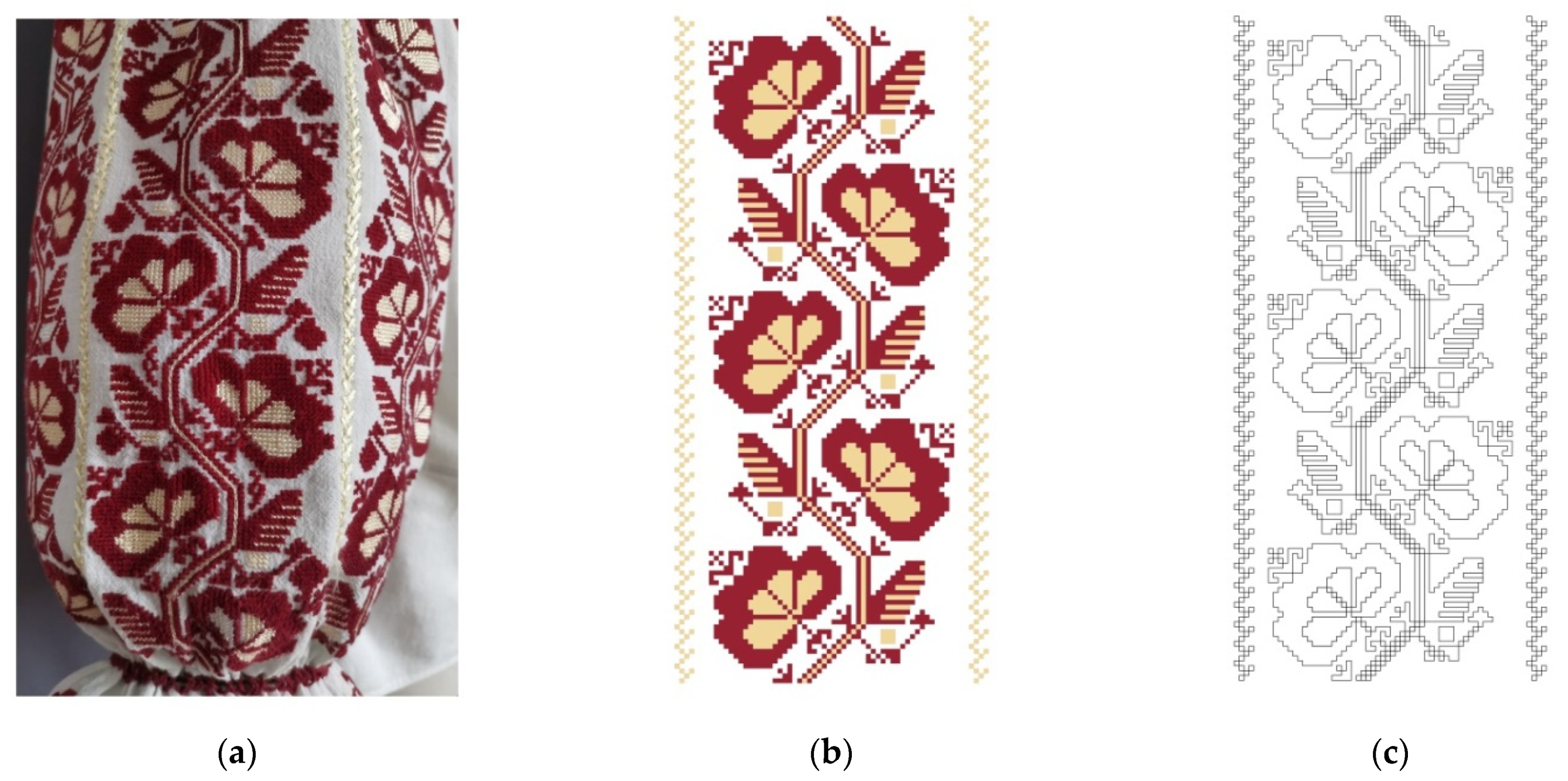
:1. Introduction
2. Materials and Methods
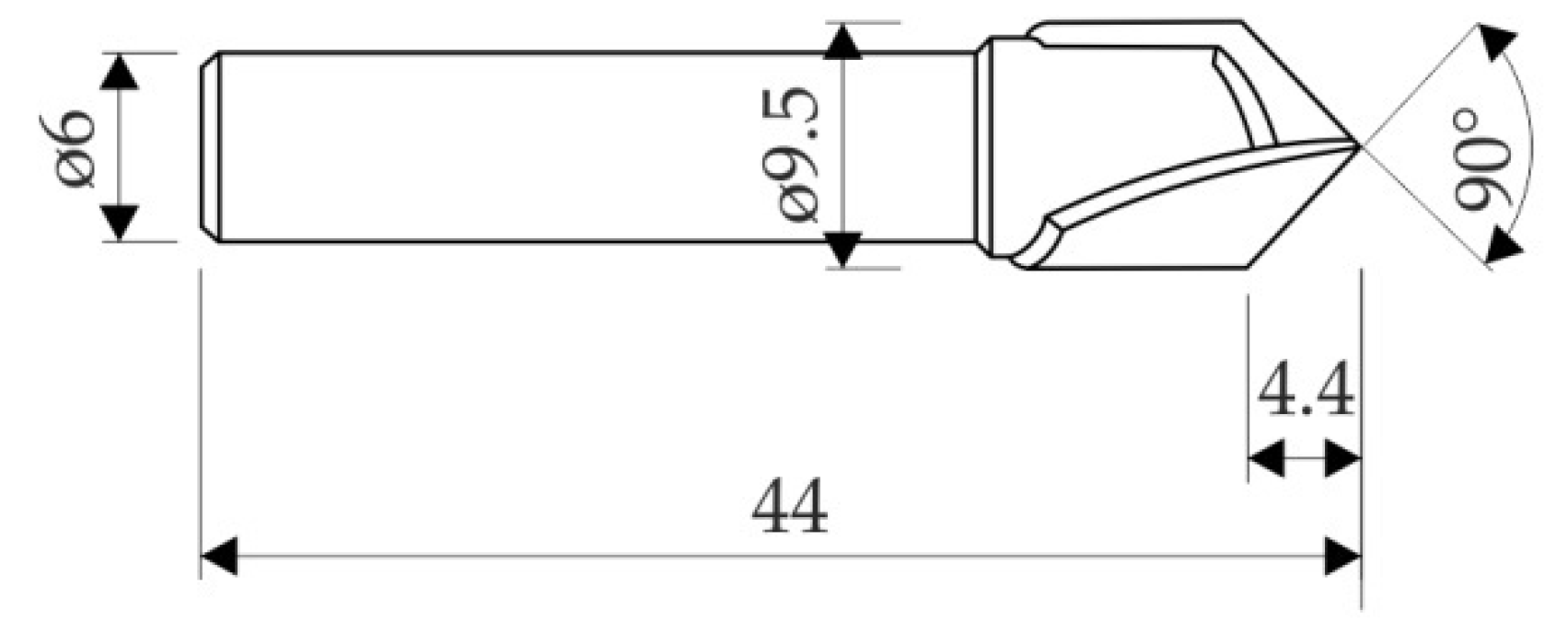
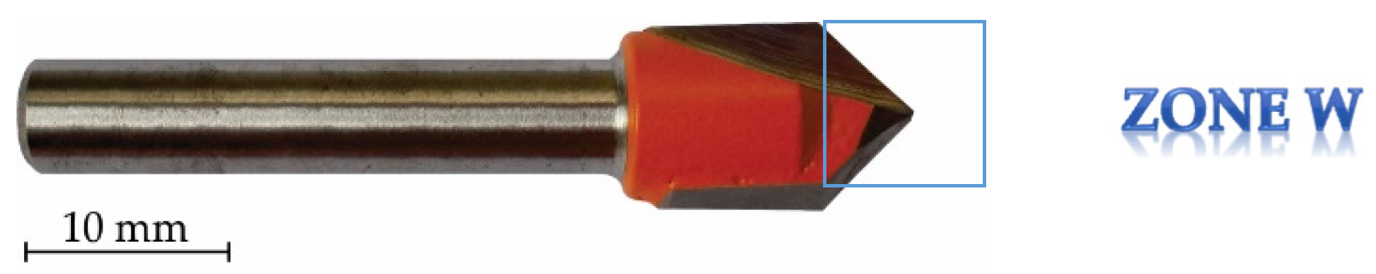
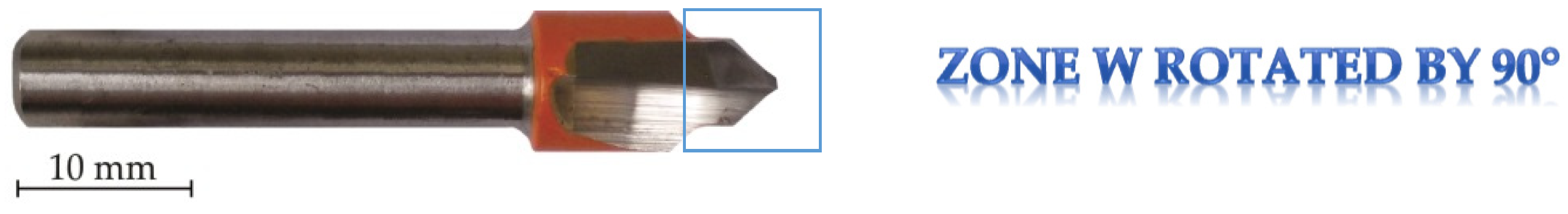
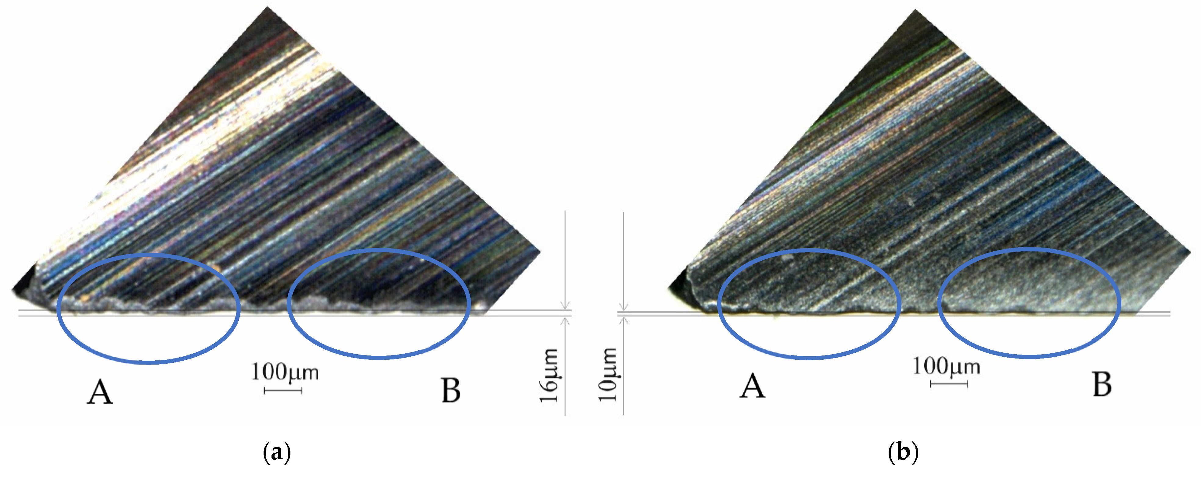
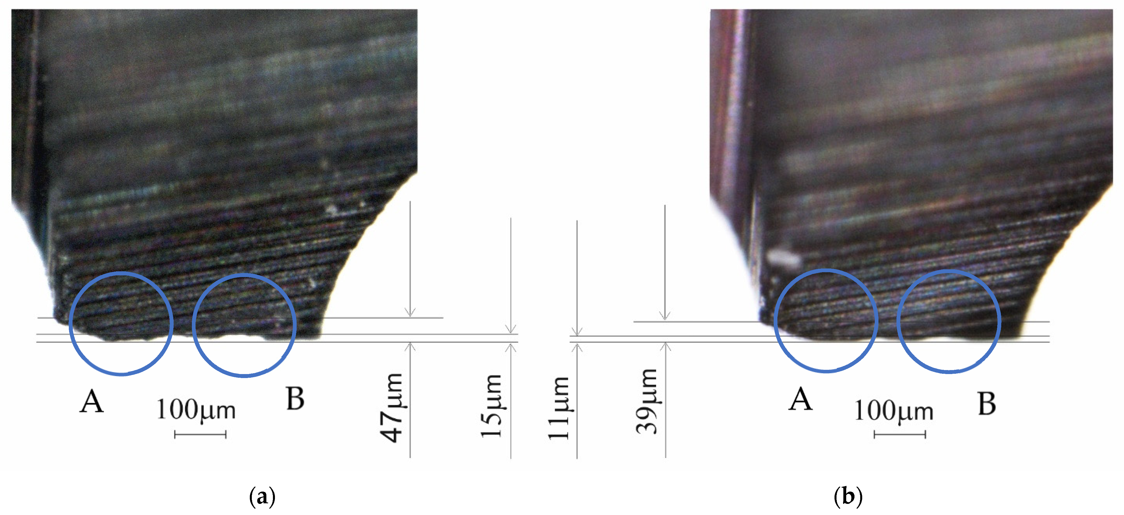
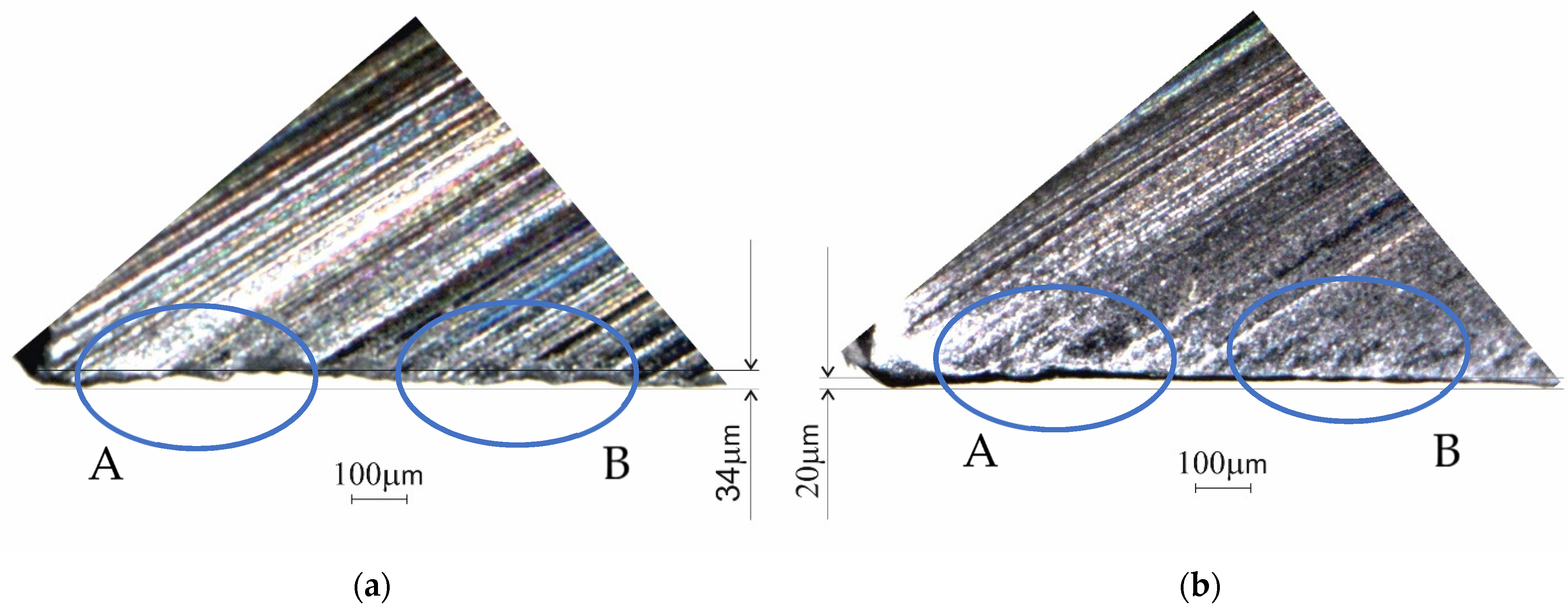
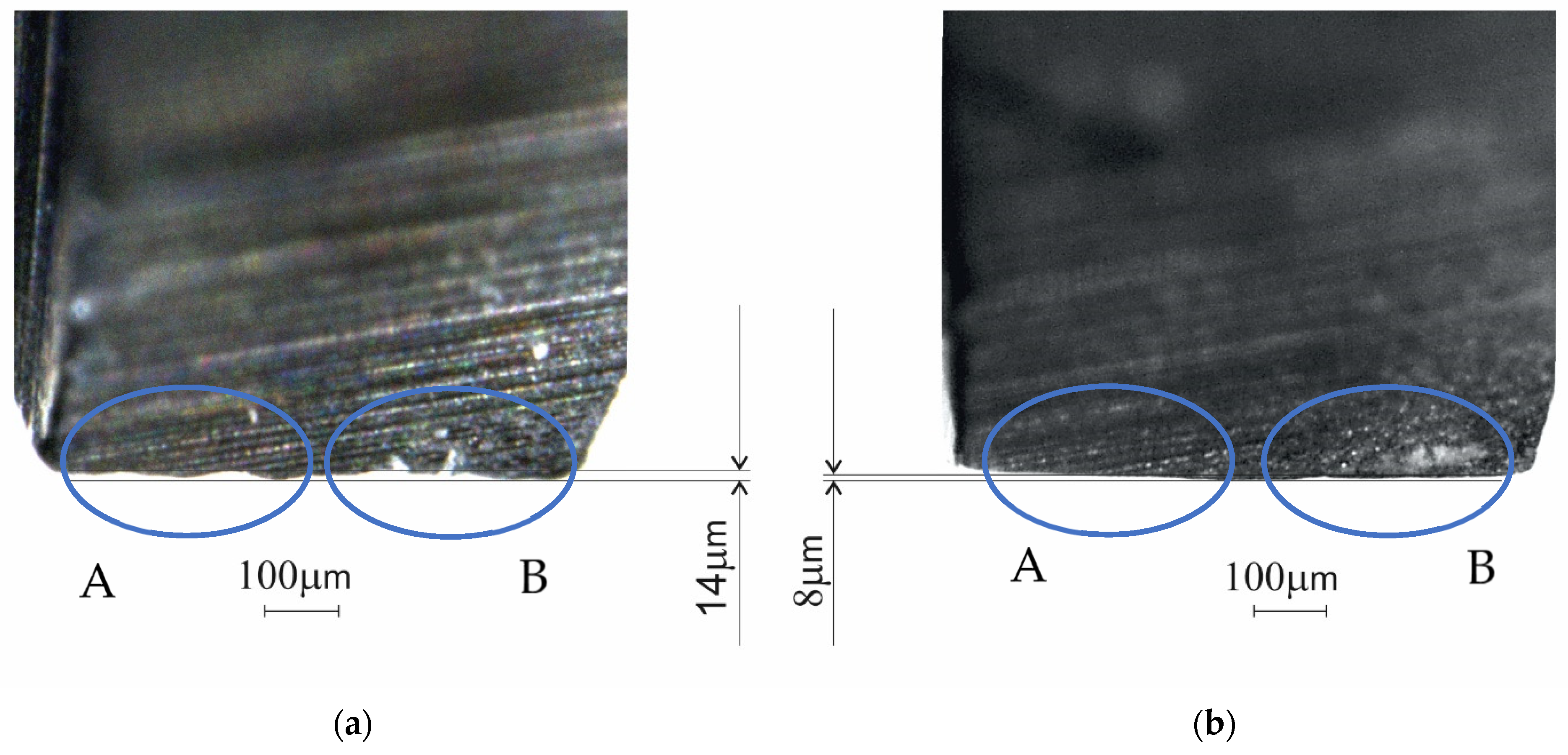
2.1. Method to Analyse Tool Wear
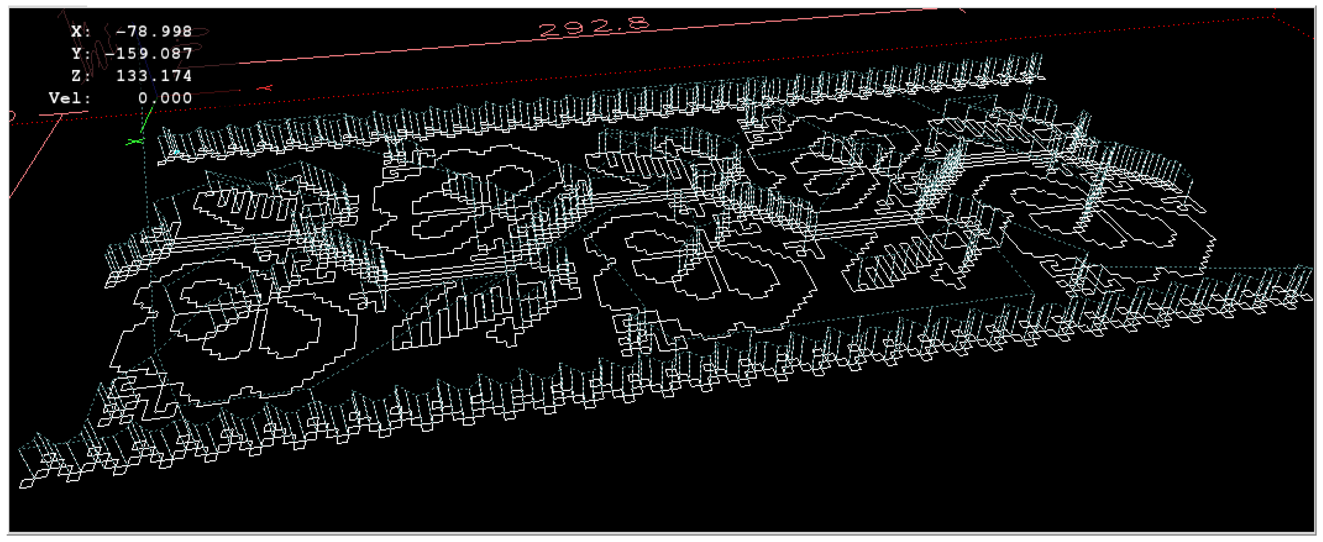
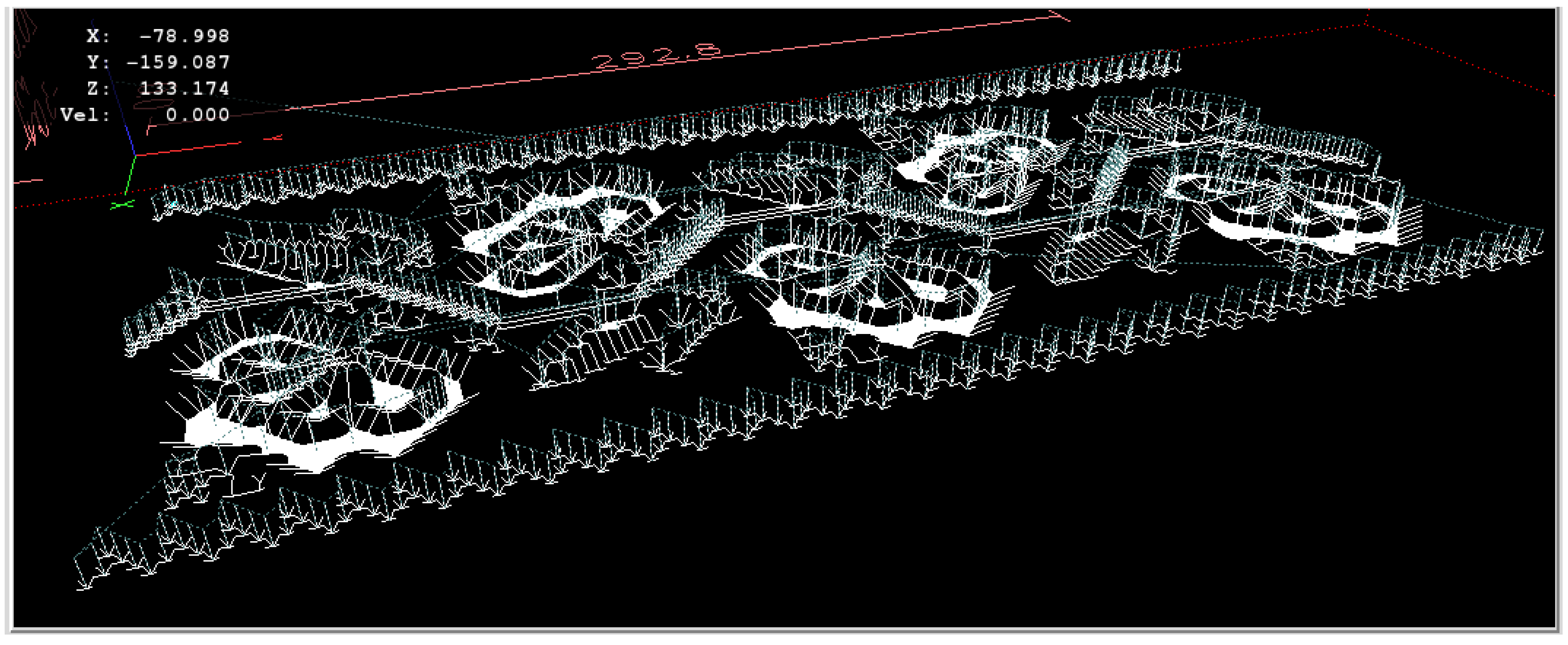
2.2. Simulation of Tool Path
2.3. Method to Analyze the Wood Ornaments Produced
3. Results
3.1. Tool Wear
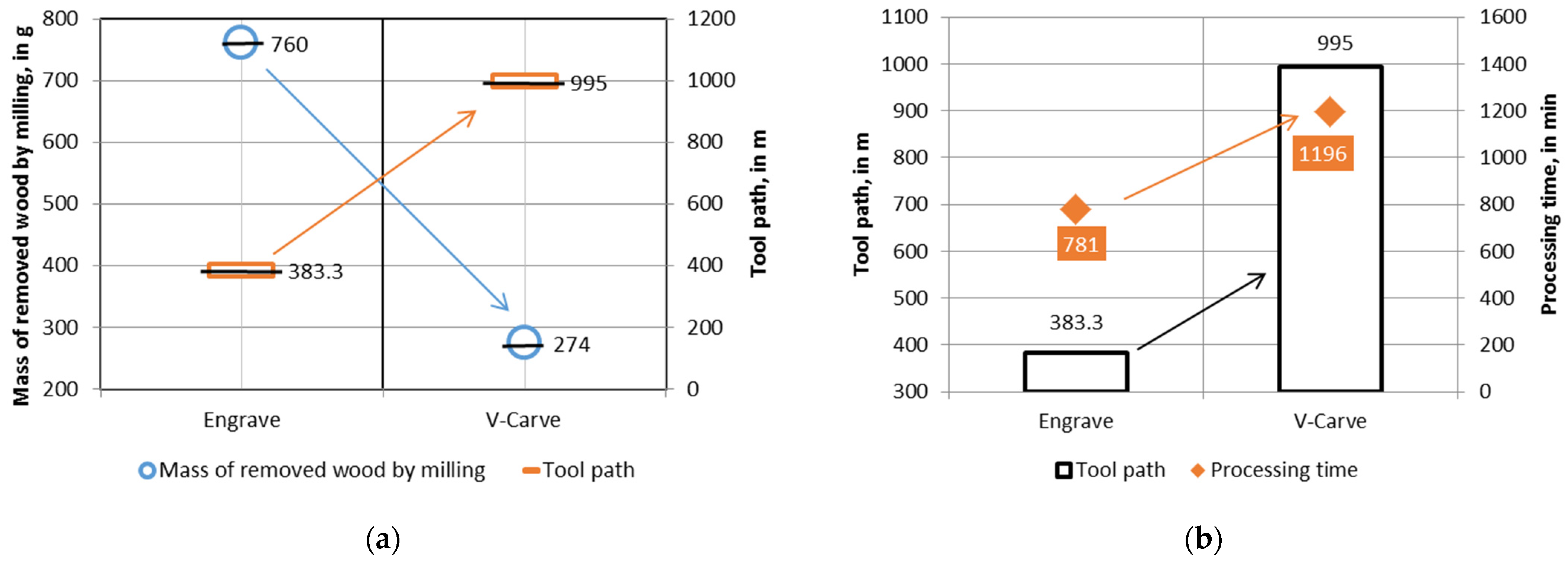
3.2. Tool Path
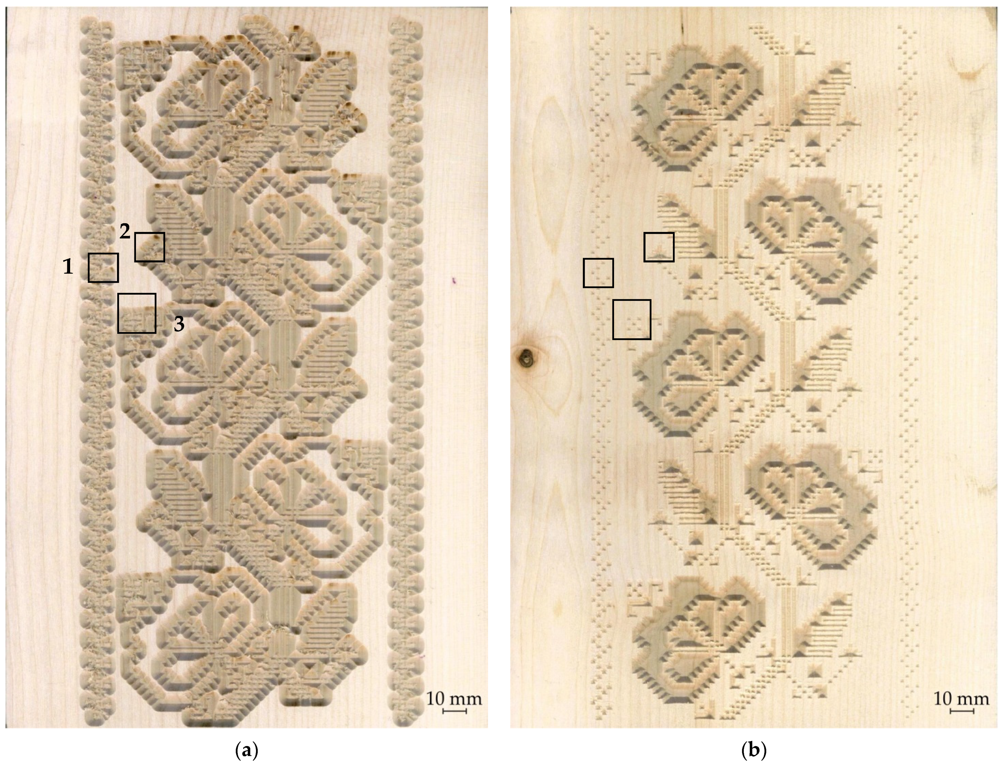
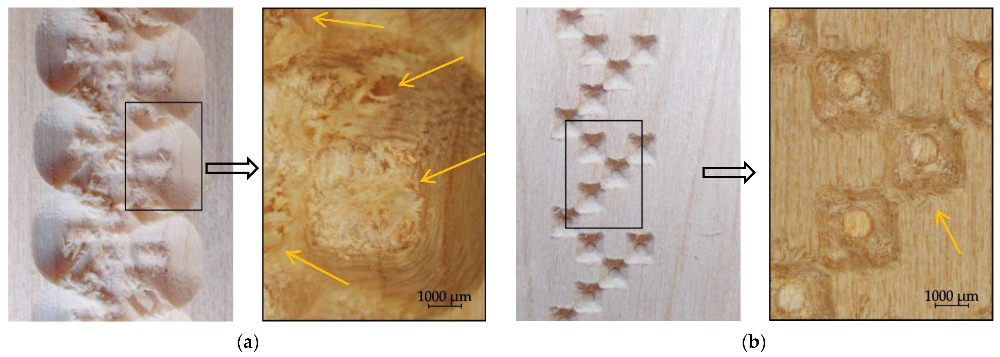
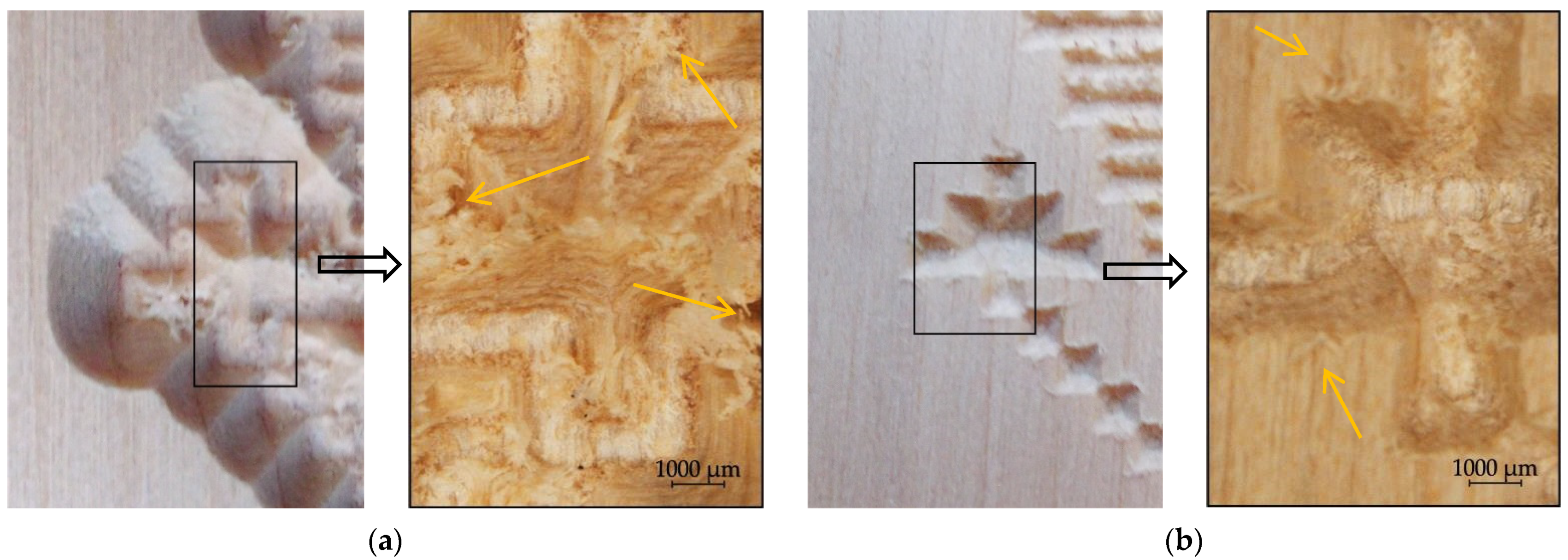
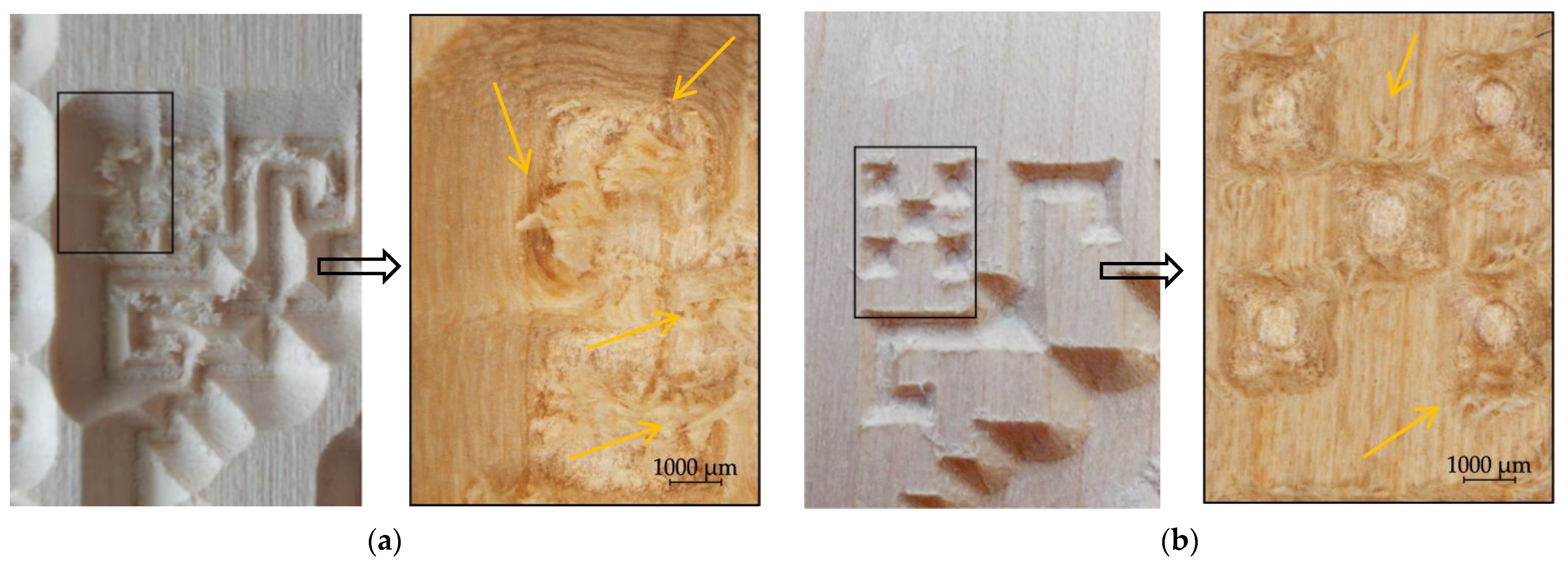
3.3. Wood Ornaments Investigation
4. Discussion
5. Conclusions
Author Contributions
Funding
Institutional Review Board Statement
Informed Consent Statement
Data Availability Statement
Acknowledgments
Conflicts of Interest
References
- Ilieş, D.C.; Herman, G.V.; Caciora, T.; Ilieş, A.; Indrie, L.; Wendt, J.; Axinte, A.; Diombera, M.; Lite, C.; Berdenov, Z.; et al. Considerations Regarding the Research for the Conservation of Heritage Textiles in Romania. In Waste in Textile and Leather Sectors; Körlü, A., Ege University, Eds.; IntechOpen Limited: London, UK, 2020. [Google Scholar] [CrossRef] [Green Version]
- Doble, L.; Stan, O.; Suteu, M.D.; Albu, A.; Bohm, G.; Tsatsarou-Michalaki, A.; Gialinou, E. Romanian traditional motif—element of modernity in clothing. IOP Conf. Ser. Mater. Sci. Eng. 2017, 254, 172009. [Google Scholar] [CrossRef]
- Fairclough, G. The Value of Heritage for the Future. In Heritage in Society. Cultural Policy and Management (KPY); Yearbook 3; Ünsal, D., Ed.; Istanbul Bilgi University Press: Istanbul, Turkey, 2012; pp. 34–41. [Google Scholar]
- Sood, S.; Duvedi, R.K.; Bedi, S.; Mann, S. 3D representation and CNC machining of 2D digital images. Procedia Manuf. 2018, 26, 10–20. [Google Scholar] [CrossRef]
- Pinkowski, G.; Szymanski, W.; Nosowski, T. Analyses of surface roughness in selected wood species after machining on a CNC woodworking centre. Ann. WULS SGGW For. Wood Technol. 2012, 79, 164–169. [Google Scholar]
- Çakiroğlu, E.O.; Demir, A.; Aydin, I. Determination of the Optimum Feed Rate and Spindle Speed Depending on the Surface Roughness of Some Wood Species Processed with CNC Machine. J. Anatol. Environ. Anim. Sci. 2019, 4, 598–601. [Google Scholar] [CrossRef]
- Hazir, E.; Koc, K.H. Optimization of wood machining parameters in CNC Routers: Taguchi orthogonal array based simulated angling algorithm. Maderas Cienc. Tecnol. 2019, 21, 493–510. [Google Scholar] [CrossRef] [Green Version]
- Sütcü, A.; Karagöz, Ü. Effect of machining parameters on surface quality after face milling of MDF. Wood Res. 2012, 57, 231–240. [Google Scholar]
- Supadarattanawong, S.; Rodkwan, S. An Investigation of the Optimal Cutting Conditions in Parawood (Heavea Brasiliensis) Machining Process on a CNC Wood Router. Kasetsart J. (Nat. Sci.) 2006, 40, 311–319. [Google Scholar]
- Gawronski, T. Optimisation of CNC routing operations of wooden furniture parts. Int. J. Adv. Manuf. Technol. 2013, 67, 2259–2267. [Google Scholar] [CrossRef] [Green Version]
- Krimpenis, A.A.; Fountas, N.A.; Mantziouras, T.; Vaxevanidis, N.M. Optimizing CNC wood milling operations with the use of genetic alghorithms on CAM software. Wood Mater. Sci. Eng. 2014, 11, 102–115. [Google Scholar] [CrossRef]
- Ohuchi, T.; Murase, Y. Milling of wood and wood-based materials with a computerized numerically controlled router V: Development of adaptive control grooving system corresponding to progression of tool wear. Wood Sci. 2006, 52, 395–400. [Google Scholar] [CrossRef]
- Aguilera, A.; Meausoone, P.J.; Rolleri, A.; Barros, J.L.; Burgos, F.; Aguilar, C. Advances on indirect methods to evaluate tool wear for Radiata pine solid wood molding. Wear 2016, 350–351, 27–34. [Google Scholar] [CrossRef]
- Pinkowski, G.; Szymanski, W.; Gilewicz, A.; Krauss, A. Impact of the wear of the cutting edge on selected parameters of the surface geometric structure after wood milling. Ann. WULS SGGW For. Wood Technol. 2009, 69, 187–191. [Google Scholar]
- Keturakis, G.; Lisauskas, V. Influence of the Sharpness Angle on the Initial Wear of the Wood Milling Knives. Mater. Sci. (Medžiagotyra) 2010, 16, 205–209. [Google Scholar]
- Porankiewicz, B. Theoretical simulation of cutting edge wear when milling wood and wood based products. Wood Sci. Technol. 2006, 40, 107–117. [Google Scholar] [CrossRef]
- Aknouche, A.; Outahyon, A.; Nouveau, C.; Marchal, R.; Zerizer, A.; Butaud, J.C. Tool wear effect on cutting forces: In routing process of Aleppo pine wood. J. Mat. Process. Technol. 2009, 209, 2918–2922. [Google Scholar] [CrossRef] [Green Version]
- Antonescu, R.B. Dicţionar de Simboluri şi Credinţe Tradiţionale Româneşti; Ediţie digitală, Direcţia de cercetare, evidenţă a patrimoniului cultural mobil, imaterial şi digital; Institutul Național al Patrimoniului: București, România, 2016; p. 661. [Google Scholar]
- Semne Cusute. Available online: https://semne-cusute.blogspot.com/2012/07/motive-unda-apei.html (accessed on 5 June 2021).
- Semne Cusute. Available online: https://semne-cusute.blogspot.com/2012/07/bradutul.html (accessed on 5 June 2021).
- CMT Orange Tools. Available online: https://www.cmtorangetools.com/eu-en/industrial-router-bits/v-grooving-router-bits-90deg (accessed on 5 June 2021).


| No. | Method | Mass of Removed Wood 1, in kg/Panel | Tool Path, in m/Panel | Processing Time, in min:s/Panel |
|---|---|---|---|---|
| 1 | Engrave | 0.038 | 19.165 | 39:03 |
| (0.005) | ||||
| 2 | V-Carve | 0.014 | 49.741 | 59:48 |
| (0.002) |
Publisher’s Note: MDPI stays neutral with regard to jurisdictional claims in published maps and institutional affiliations. |
© 2021 by the authors. Licensee MDPI, Basel, Switzerland. This article is an open access article distributed under the terms and conditions of the Creative Commons Attribution (CC BY) license (https://creativecommons.org/licenses/by/4.0/).
Share and Cite
Lungu, A.; Ispas, M.; Brenci, L.-M.; Răcăşan, S.; Coşereanu, C. Comparative Study on Wood CNC Routing Methods for Transposing a Traditional Motif from Romanian Textile Heritage into Furniture Decoration. Appl. Sci. 2021, 11, 6713. https://0-doi-org.brum.beds.ac.uk/10.3390/app11156713
Lungu A, Ispas M, Brenci L-M, Răcăşan S, Coşereanu C. Comparative Study on Wood CNC Routing Methods for Transposing a Traditional Motif from Romanian Textile Heritage into Furniture Decoration. Applied Sciences. 2021; 11(15):6713. https://0-doi-org.brum.beds.ac.uk/10.3390/app11156713
Chicago/Turabian StyleLungu, Antonela, Mihai Ispas, Luminiţa-Maria Brenci, Sergiu Răcăşan, and Camelia Coşereanu. 2021. "Comparative Study on Wood CNC Routing Methods for Transposing a Traditional Motif from Romanian Textile Heritage into Furniture Decoration" Applied Sciences 11, no. 15: 6713. https://0-doi-org.brum.beds.ac.uk/10.3390/app11156713