Article

Transient Attitude Motion of TNS-0#2 Nanosatellite during Atmosphere Re-Entry

1
Keldysh Institute of Applied Mathematics RAS, 125047 Moscow, Russia
2
JSC Russian Space Systems, 111250 Moscow, Russia
*
Author to whom correspondence should be addressed.
Submission received: 9 June 2021 / Revised: 13 July 2021 / Accepted: 20 July 2021 / Published: 23 July 2021
(This article belongs to the Special Issue Small Satellites Missions and Applications)

Abstract

:
Attitude motion reconstruction of the Technological NanoSatellite TNS-0 #2 during the last month of its mission is presented in the paper. The satellite was designed to test the performance of the data transmission via the Globalstar communication system. This system successfully provided telemetry (even during its atmosphere re-entry) up to an altitude of 156 km. Satellite attitude data for this phase is analyzed in the paper. The nominal satellite attitude represents its passive stabilization along a geomagnetic field induction vector. The satellite was equipped with a permanent magnet and hysteresis dampers. The permanent magnet axis tracked the local geomagnetic field direction with an accuracy of about 15 degrees for almost two years of the mission. Rapid altitude decay during the last month of operation resulted in the transition from the magnetic stabilization to the aerodynamic stabilization of the satellite. The details of the initial tumbling motion after the launch, magnetic stabilization, transition phase prior to the aerodynamic stabilization, and subsequent satellite motion in the aerodynamic stabilization mode are presented.

1. Introduction

Passive attitude control systems are quite popular for nano, pico, and femto-satellites due to strict limitations in terms of mass, size, cost, and energy. These systems utilize natural magnetic, gravitational, or aerodynamic torques to provide the passive stabilization required for missions. Each type of passive stabilization provides different satellite attitudes. Gravitational torque aligns the minimum moment of inertia axis along the nadir direction. Magnetic torque provides tracking of the local geomagnetic field direction by the onboard magnetic dipole. Each type of passive attitude control system is effective on different altitudes. The ratio between the magnitudes of these major environmental torques changes as the satellite orbit evolves. This transforms into changes of the attitude motion regimes during a satellite’s lifetime. These regimes of the passively controlled satellites have well-studied both theoretically and experimentally onboard a large number of satellites with gravitational [1,2,3,4], magnetic [5,6,7,8,9,10] and aerodynamic [11,12,13,14,15] control systems. The transient motion between the magnetic and aerodynamic attitude stabilization regimes during the orbit altitude degradation has not been investigated experimentally yet to the best of our knowledge. This is due to the extremely short time between the entering of the dense upper atmospheric layers and the satellite operation termination due to heating. Telemetry gathering is a difficult task for this period. Therefore, the sensor measurements necessary for the attitude motion reconstruction are rarely available for the last weeks of the satellite operation. Technological NanoSatellite TNS-0 #2 utilized GlobalStar antennas [16] as its main data transfer device. This provided frequent communication sessions even during the last days of the mission in the upper atmosphere.
The nominal satellite attitude was a passive magnetic stabilization. The longitudinal axis of the satellite was approximately directed along the local geomagnetic induction vector with a deviation no greater than 12 degrees. The satellite had a relatively elongated geometry with significant displacement between the centers of mass and pressure. The influence of the aerodynamic torque rapidly increased as the satellite entered the dense layers of the atmosphere. On 10 August 2019, the magnetic stabilization changed to an almost chaotic motion with a high angular velocity. Aerodynamic stabilization was achieved in about two weeks. This motion was maintained until its breakdown in the atmosphere on 6 September 2019. Chaotic tumbling was observed during the breakdown.
The structure of the paper is as follows. First, the TNS-0 #2 description is presented. Then, the attitude motion equations (taking into account the magnetic and aerodynamic torques) are provided and a short explanation of the motion reconstruction technique is given. This technique is then applied to process the telemetry received during the magnetic stabilization, transient motion, and aerodynamic stabilization.

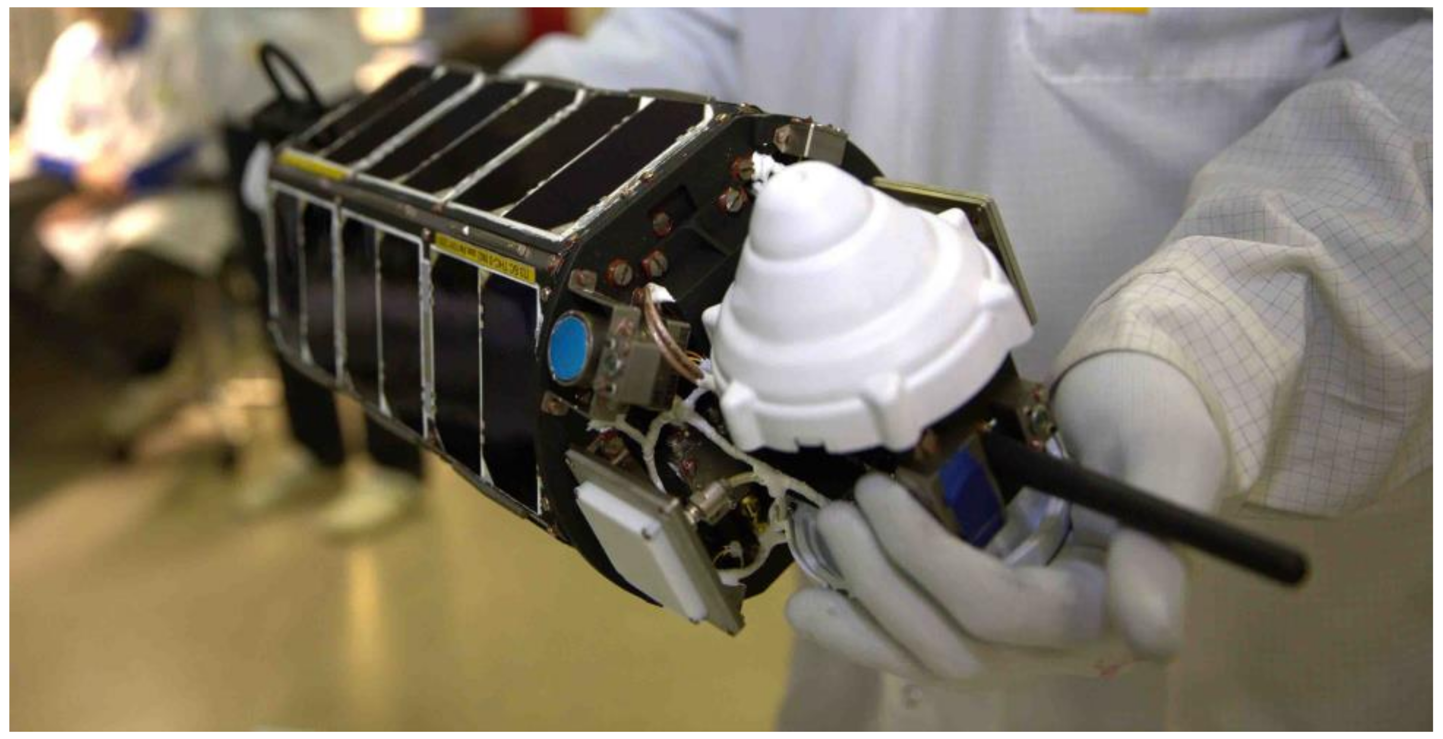
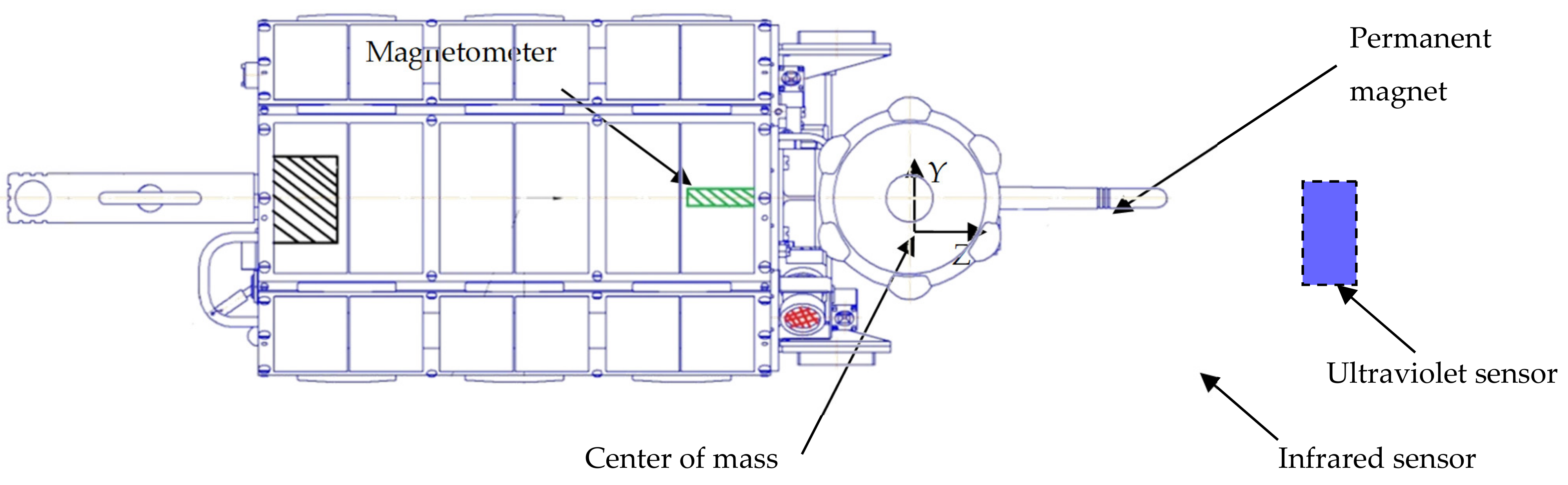
2. TNS-0 #2 Description

The TNS-0#2 nanosatellite was developed by JSC Russian Space Systems. It was successfully launched on 17 August 2017 from the International Space Station during the spacewalk of Russian cosmonauts. TNS-0 #2 nanosatellite is a hexagonal prism with a 26.4 cm height and an 18.7 cm diameter. The sides are covered with solar panels. Globalstar antennas, a set of Sun sensors, and a radio link antenna are located on the upper side of the satellite. A handle is attached at the bottom for the cosmonaut to hold the satellite during the spacewalk. The satellite is presented in Figure 1.
The mass of the satellite is 4.8 kg and its center of mass is located almost on the axis of geometric symmetry of the satellite body, as shown in Figure 2. The inertia tensor in the reference frame with the origin in the center of mass of the satellite is
J = 0.06153 0.00013 0.00033 0.00013 0.06669 0.00012 0.00033 0.00012 0.01287 kg · m 2 .
The satellite is equipped with the passive magnetic attitude control system developed by the Keldysh Institute of Applied Mechanics of RAS. The system consists of a set of hysteresis rods for the angular velocity damping and a permanent magnet located along the axis of symmetry to stabilize this axis along the local geomagnetic field induction vector. The dipole moment magnitude of the permanent magnet is 2.2 A·m2. Grids of hysteresis rods were installed on the upper and lower sides of the nanosatellite body. The location of the permanent magnet, magnetometer, and Sun sensors is shown in Figure 2.
Three-axis magnetometer and a set of Sun sensors were installed onboard. Attitude motion was reconstructed using their measurements. The measurements root-mean-square error of the magnetometer is σ = 100 nT. The non-orthogonality of the measuring axes is not worse than 1 degree. Eight optical sensors are installed on the nanosatellite THS-0 #2: six photodiode sensors, one ultraviolet Sun sensor, and one infrared horizon sensor.
More details on the passive attitude control system can be found in [17].

3. Attitude Motion Reconstruction Technique

In this section, a technique for the sensors’ measurements processing of TNS-0 #2 is presented. A mathematical model of the angular motion of the nanosatellite with relevant assumptions is provided.

3.1. TNS-0#2 Attitude Motion Equations

Consider the motion of a satellite with hysteresis rods and a permanent magnet, taking into account both gravitational and aerodynamic torques. Assume that the satellite is a rigid body moving along a circular orbit around the Earth. The geomagnetic field model is IGRF [18]. The parallelogram model is used to describe the effect of the hysteresis in rods [19].
The following reference frames are used in the paper. O X O Y O Z O is the orbital reference frame with the origin placed in the satellite center of mass. The axis O Z O is directed along the satellite radius-vector from the Earth center. O Y O is perpendicular to the orbital plane, and axis O X O complements these axes. O X Y Z is the body-fixed reference frame, and its axes are directed as shown in Figure 2.
The attitude motion is described using the Euler equations and kinematic relations based on the quaternion. The satellite state vector consists of the absolute angular velocity vector Ω and the attitude quaternion Λ = q , q 0 . Here q is the vector part of the quaternion and q 0 is the scalar part. Additionally, the direction cosines matrix A is used for the torques formulation and for the attitude representation.
The dynamical motion equations are as follows:
J Ω ˙ + Ω × J Ω = M m a g + M g r a v + M h y s t + M a e r o
where J is the inertia tensor, M m a g , M g r a v , M h y s t , and M a e r o are the magnetic torque caused by the permanent magnet, gravitational torque, magnetic torque due to the hysteresis rods, and aerodynamic torque, respectively. The gravitational torque is
M g r a v = 3 ω 0 2 A e 3 × J A e 3
where e 3 = 0 0 1 T is a local vertical vector written in the orbital reference frame, and ω 0 is the orbital angular velocity vector ω 0 = 0 ω 0 0 T . The torque due to the permanent magnet is as follows:
M m a g = m × B
where m is the dipole moment of the permanent magnet, B is the geomagnetic induction vector. The torque caused by the hysteresis rods is
M h y s t = m h y s t × B
where m h y s t is the resulting dipole magnetic moment of all the rods. The dipole moment of one rod is
m h y s t k = μ k V k H 0 W e k / μ 0
where μ k is the relative magnetic permeability of the k-th rod, V k is its volume, H 0 is the mean magnitude of the geomagnetic H -field in the current point of the orbit, W ( H τ ) is a dimensionless function describing the dependence of the induction of the rod related to H 0 according to the parallelogram hysteresis model, μ 0 is the magnetic constant, and H τ = H e k , e k is the unit vector directed along the rod in the body reference frame.
The aerodynamic torque is
M a e r o = d × f a .
Vector d determines the position of the satellite centre of mass relative to the centre of pressure, and f a is the aerodynamic drag force acting on the side in the body-fixed reference frame. The sum over all sides facing the incoming flow is performed.
Dynamic equations are supplemented with kinematic relations. The attitude quaternion is used in the numerical simulation. Its kinematic equation is as follows:
Λ ˙ = 1 2 C Λ C = 0 ω 3 ω 2 ω 1 ω 3 0 ω 1 ω 2 ω 2 ω 1 0 ω 3 ω 1 ω 2 ω 3 0 .
Here ω = [ ω 1 , ω 2 , ω 3 ] T is the angular velocity vector relative to the orbital reference frame,
ω = Ω A ω 0
These equations are used for the satellite motion reconstruction with the onboard sensors measurements.

3.2. Measurements Processing Technique

The algorithms of the attitude motion determination using on-board sensors measurements are well studied in the literature. There are two main approaches: real-time on-board motion estimation using recursive or local algorithms [20,21,22] and post-flight measurements processing for motion reconstruction [23,24,25] and for satellite parameters characterization [26,27]. The first approach is commonly used for active attitude control systems, and the second is more suitable for motion estimation of satellites with passive attitude control systems. The magnetometer measurements processing technique was used for the TNS-0 #2 nanosatellite attitude motion reconstruction. Sun sensors were not used since they are sensitive to the albedo and therefore have very low accuracy. Also, Sun sensors measurements are not available in the shadowed part of the orbit. Nevertheless, Sun sensors are used for the verification of the motion estimation established using magnetometer measurements.
The problem of the attitude motion reconstruction is formulated as follows. It is necessary to obtain such initial conditions for the attitude motion equations that the difference between the predicted measurements calculated using the measurements model and the actual measurements from the on-board sensor achieves a minimum by the mean square criterion.
Consider an initial conditions vector consisting of the quaternion vector part q ( t = 0 ) and angular velocity vector ω ( t = 0 ) :
ξ = q ( t = 0 ) , ω ( t = 0 ) T
For the given vector ξ the attitude quaternion Λ t = t k for any time t k is obtained by the integration of the motion equations. The quaternion provides the prediction of the magnetometer measurements
b ˜ mod el k = A Λ k b o k
where b ˜ model k is a predicted unit vector of the geomagnetic induction field in the orbital reference frame, and b o k is calculated according to IGRF model for a given position of the satellite (obtained using either GPS/GLONASS receiver or TLE and SGP4 model). The problem of the vector ξ determination reduces to the problem of the following function minimization
Ф ξ = k = 1 N b ˜ model k b m e a s k 2
where b m e a s k is a unit magnetometer measurements vector excluding the constant bias. The minimization of the function Ф ξ is carried out using the nonlinear optimization methods.

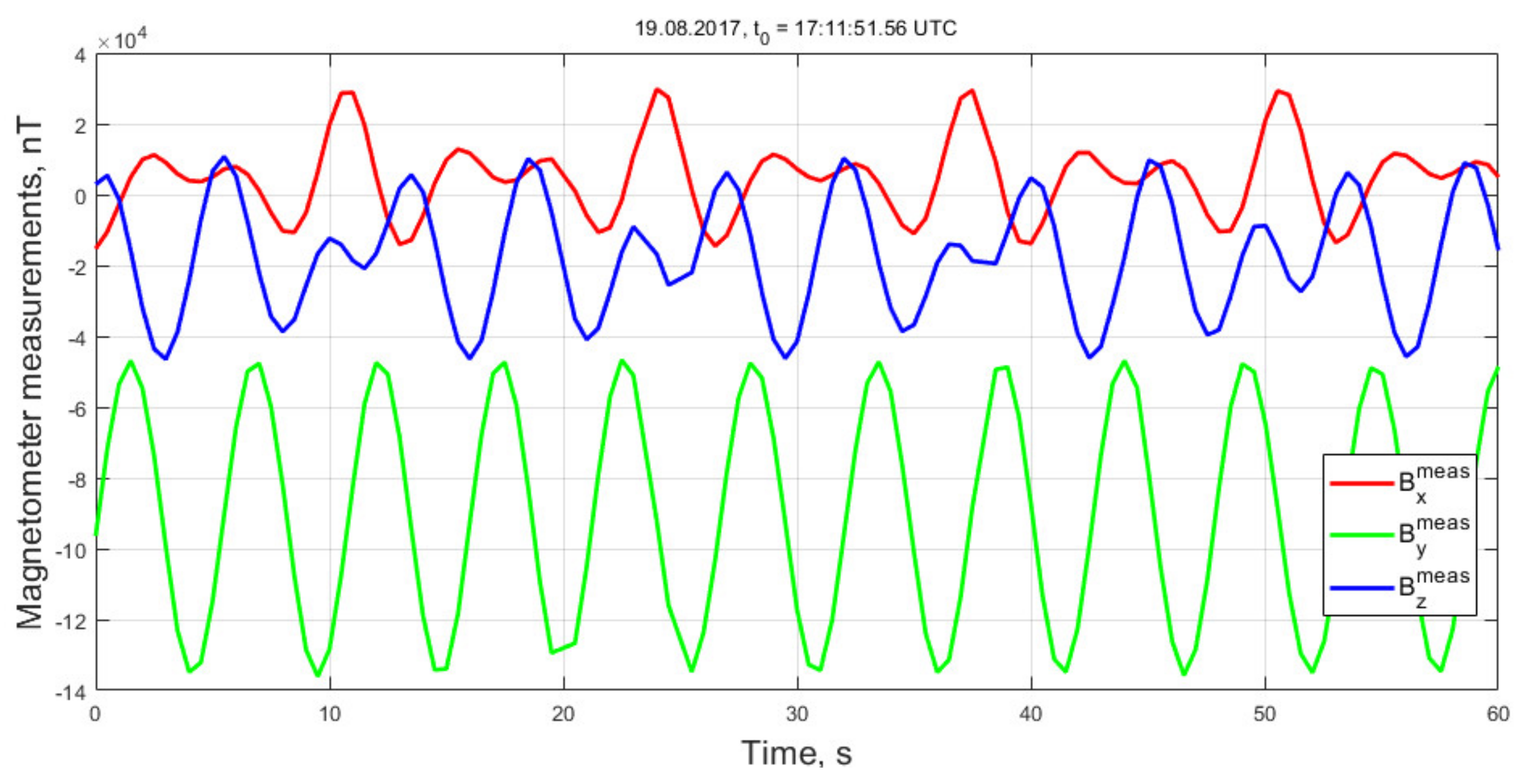
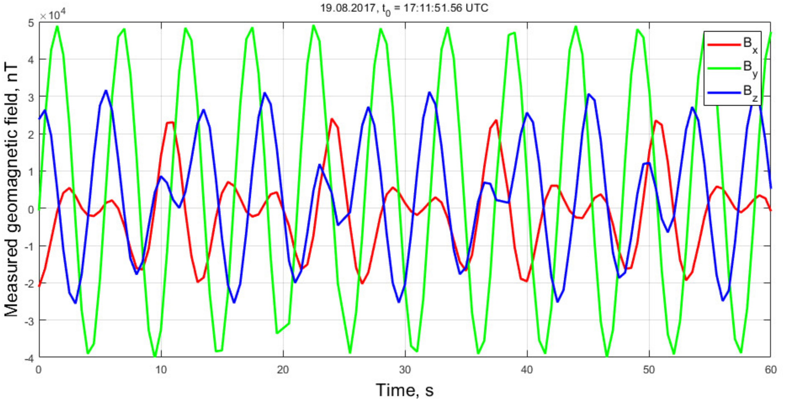
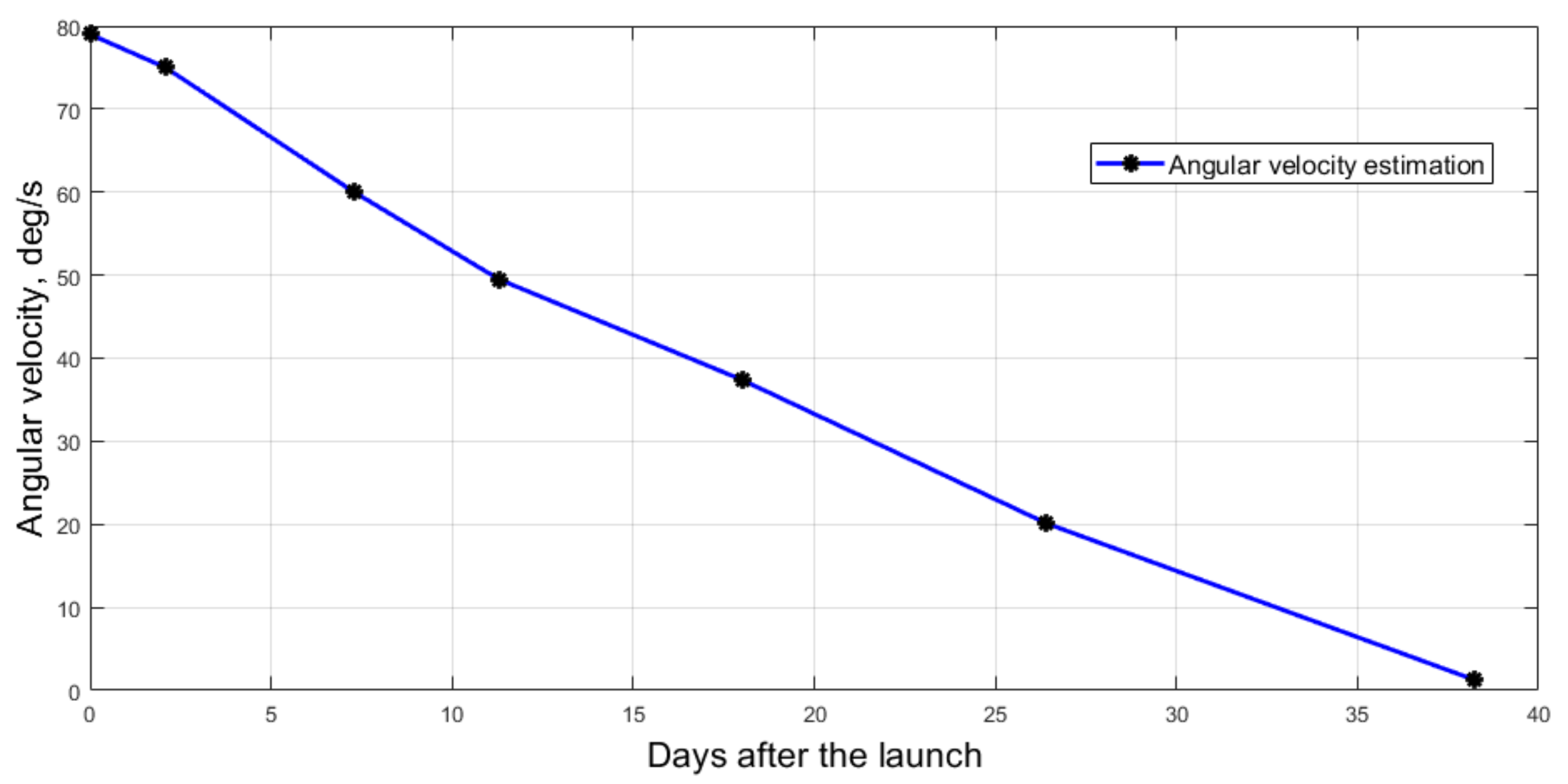
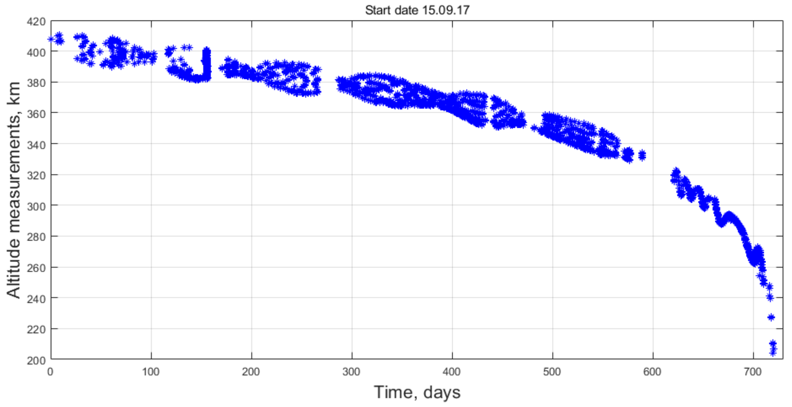
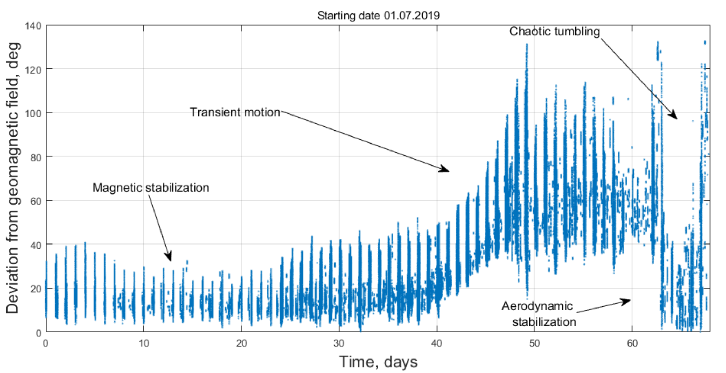
4. Measurements Processing Results and Passive Attitude Motion Regimes Analysis

4.1. Attitude Stabilization After The Launch

The first communication session that included the sensors measurements telemetry occurred on 19 August at 17 h 11 min UTC. Figure 3 shows the measurements of the magnetometer.
Magnetometer measurements include the permanent magnet and hysteresis rods influence. The main contribution is due to the magnet. The corresponding constant bias in the magnetometer measurements was estimated using the least squares method. The technique involves the functional of the difference between the field magnitudes according to the measurements and according to the IGRF model. Figure 4 shows the obtained geomagnetic field corrected for the constant bias of the magnetometer measurements B b i a s = 5.8 90.8 20.9 10 3 nT .
Figure 5 depicts the measured and predicted unit geomagnetic induction vector according to the motion reconstruction scheme discussed in previous section. The magnetometer measurements and their predicted magnitudes are close. This indicates relatively accurate satellite attitude reconstruction.
Figure 6 shows the angular velocity reconstructed according to the found initial conditions and the equations of motion. Note that the aerodynamic torque is not taken into account for the motion after the launch. The initial orbit altitude is about 420 km and the aerodynamic torque small and can be neglected.
Measurements from the Sun sensors were predicted and compared with actual measurements. It is assumed that the photodiode sensors have a sensitive area in the form of a cone with an opening angle of 120 degrees. The sensor measurements within this region are considered to have a cosine-like dependence on the incidence angle. The measurements are zero outside this region. The measurements were normalized by the maximum value according to the procedure described in [17]. Figure 7 presents a comparison of sensor measurements and their predicted values using the satellite motion model with initial conditions obtained from the magnetometer data. There is some correlation between the corresponding curves. Periodic significant discrepancy is due to the unaccounted influence of the Earth's albedo. Its contribution can reach up to 30% of the Sun's influence. In particular, non-zero measurements from Sun sensors № 4 and 5 can be explained by the effect of the light reflected from the Earth. These sensors are located at opposite sides of the satellite. This indicates the clearly low accuracy of the Sun sensors. Therefore, they are not used directly in the attitude reconstruction process. Their measurements are utilized only to validate the results of the reconstruction with the magnetometer measurements.
Figure 8 shows the time history of the angular velocity magnitude after the launch of the satellite. The curve is close to linear, which corresponds to the model of the hysteresis dampers. The damping finished and the satellite achieved the required magnetic attitude after about 36 days. This is due to a very high initial angular velocity of about 79 deg./s.

4.2. Magnetic Stabilization of TNS-0 # 2 Nanosatellite

Telemetry for approximately two orbits was stored and downloaded on 2 October for the proper assessment of the nominal magnetic stabilization motion. Figure 9 shows the deviation of OZ axis from the local magnetic field vector. This angle does not exceed 12 degrees, and the average deviation along the orbit is about 5 degrees. This is typical for a passive magnetically stabilized satellite. The characteristic period of the forced oscillations (about 9 min) caused by the uneven rotation of the local geomagnetic field induction vector is clearly seen. The frequency is close to the natural frequency of the satellite's oscillations as a rigid body with a permanent magnet in a constant external magnetic field. The period of comparatively slow amplitude variation of these oscillations (a time equal to half the satellite's revolution in orbit around the Earth) is associated with a change in the magnitude of the induction vector of the local geomagnetic field. Figure 10 depicts the angular velocity during the motion. The satellite slowly rotates around the longitudinal axis with angular velocity of 0.4 deg./s. This rotation cannot be damped by the hysteresis rods installed perpendicular to the rotation axis.
The described passive magnetic stabilization maintained since October 2017 till the last several months of the mission. The deviation of the permanent magnet axis from the local geomagnetic field for a number of months in 2018 is shown in Figure 11.
The deviation eventually increased due to the increasing influence of the aerodynamic torque as the satellite orbit decayed. The satellite altitude for the whole mission duration is shown in Figure 12 and Figure 13 shows the magnet axis deviation from the local geomagnetic field starting from 1 July 2019. The deviation increased up to 40 degrees in July. The magnetic stabilization was completely lost in August; the satellite was tumbling.
The satellite achieved aerodynamic stabilization in about two weeks. Then the satellite lost this attitude on 6 September, the last day of the mission. The transient motion and aerodynamic stabilization are discussed in the following section.

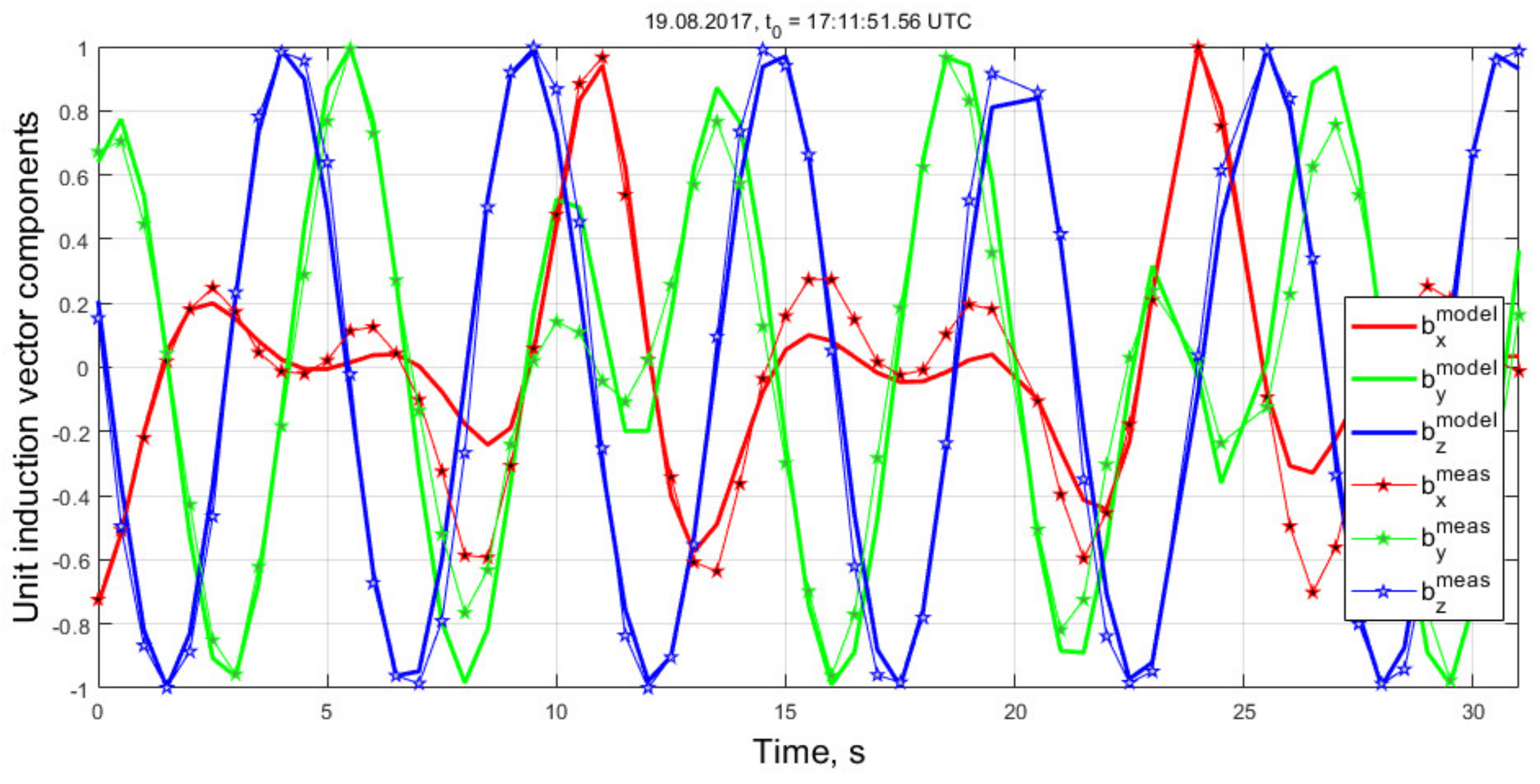
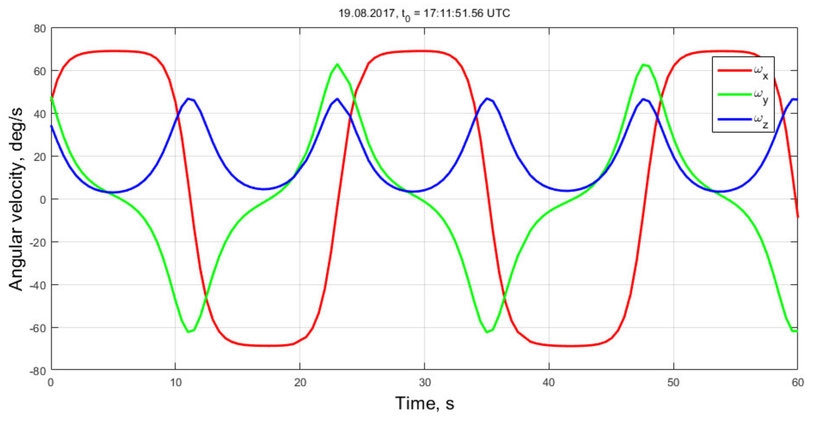
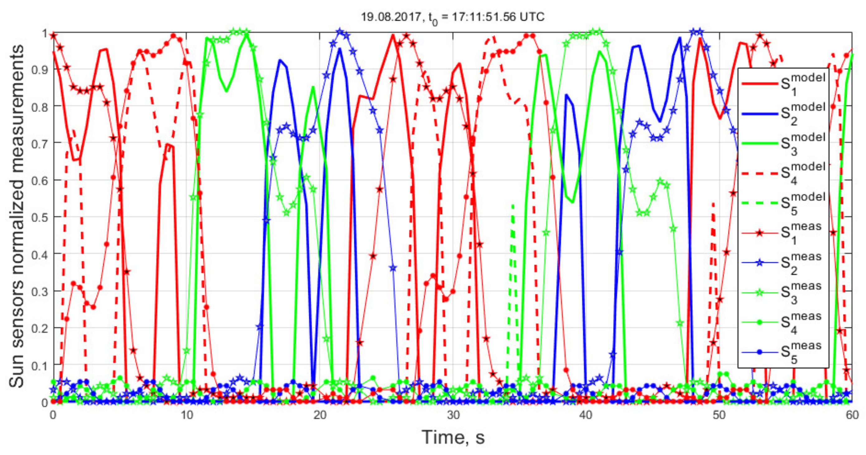
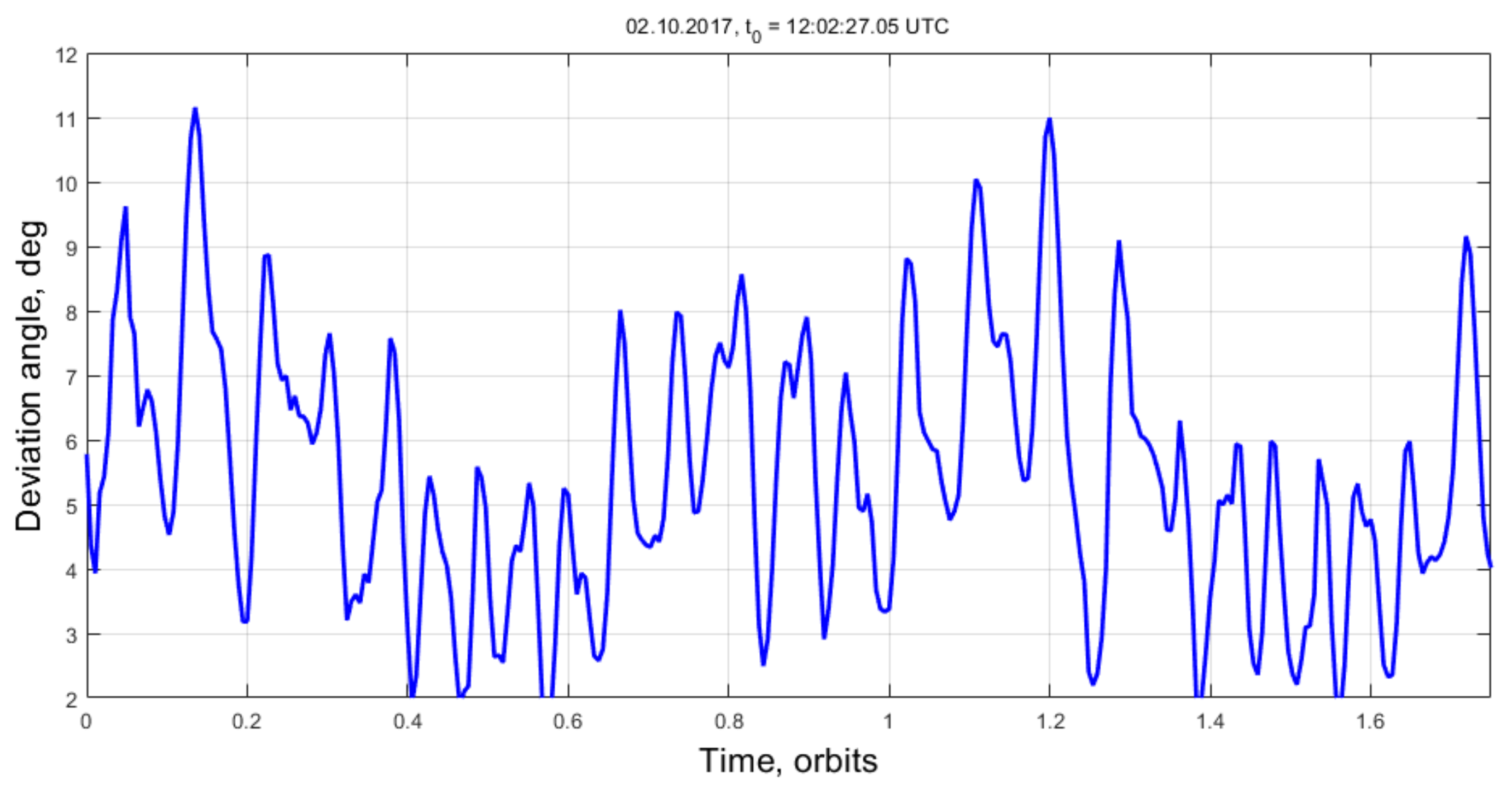
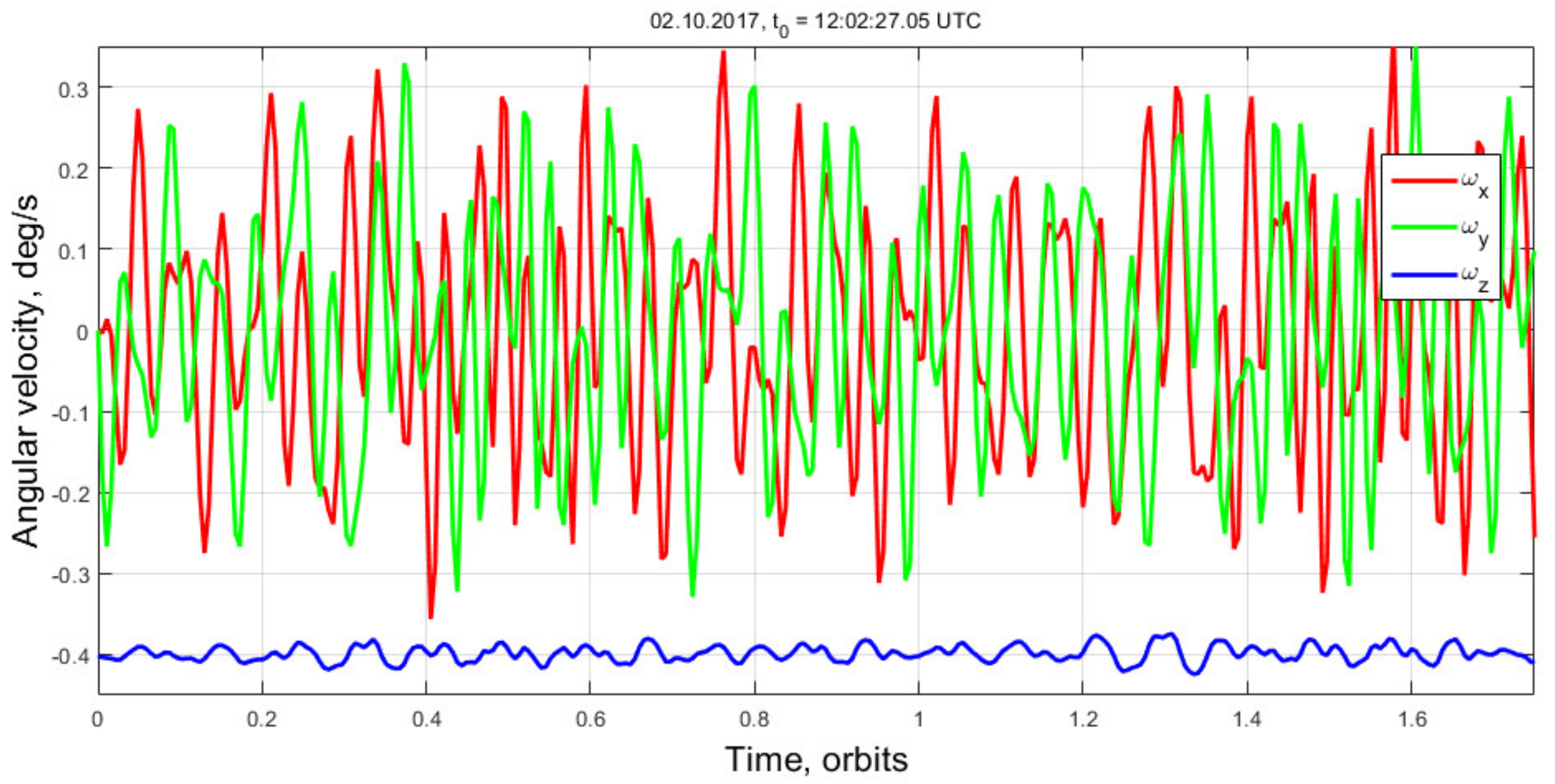
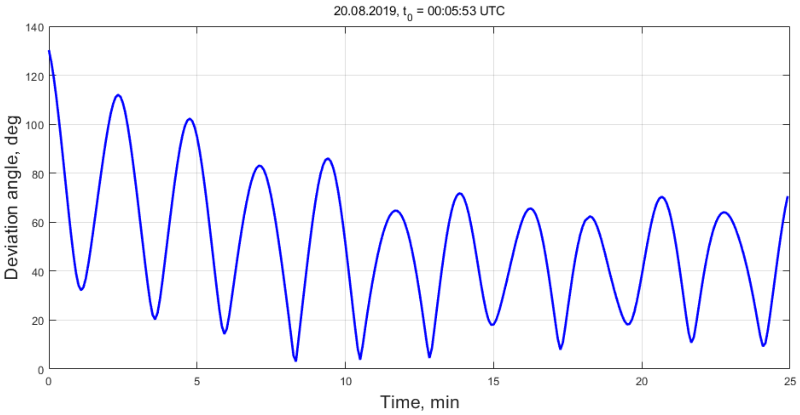
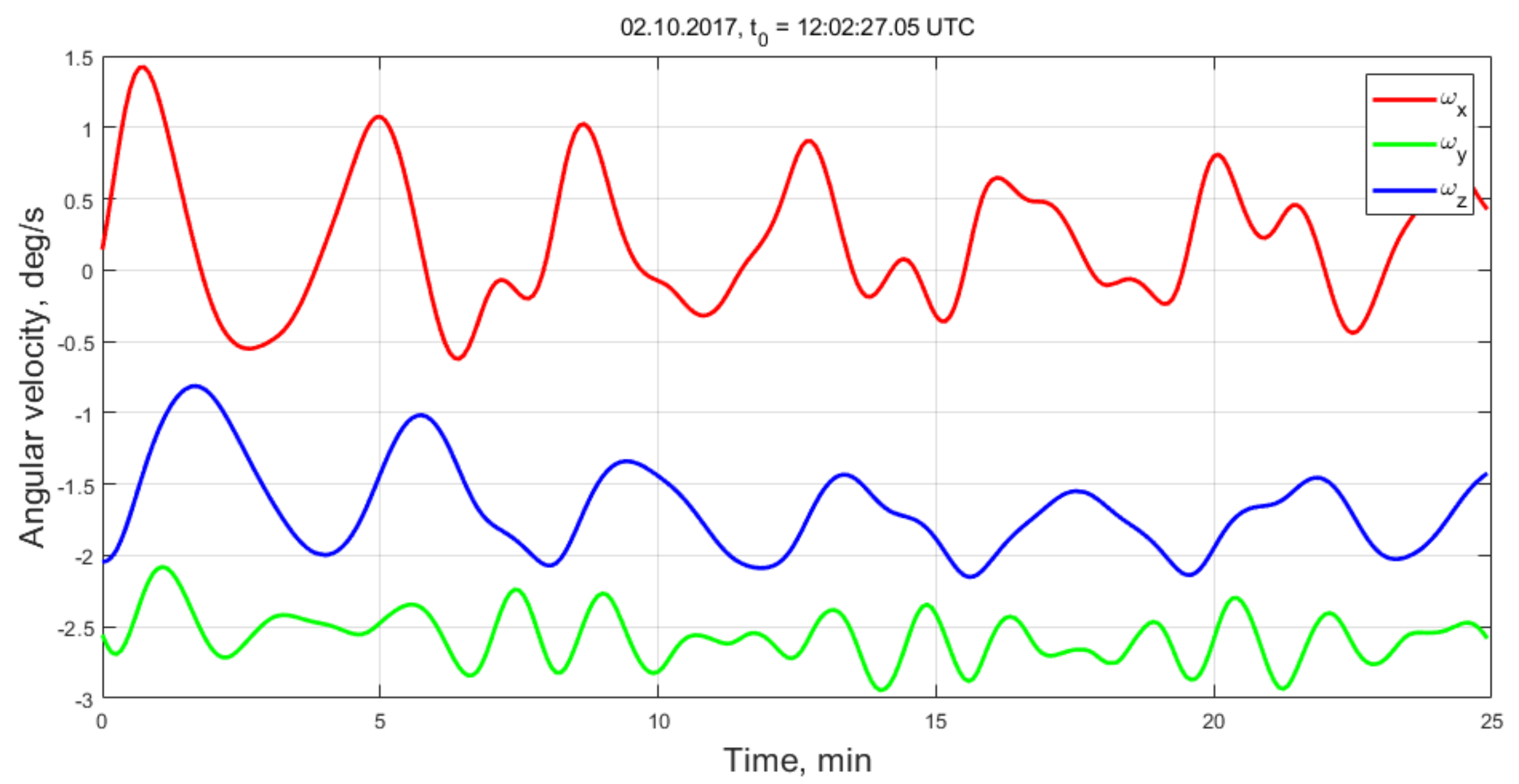
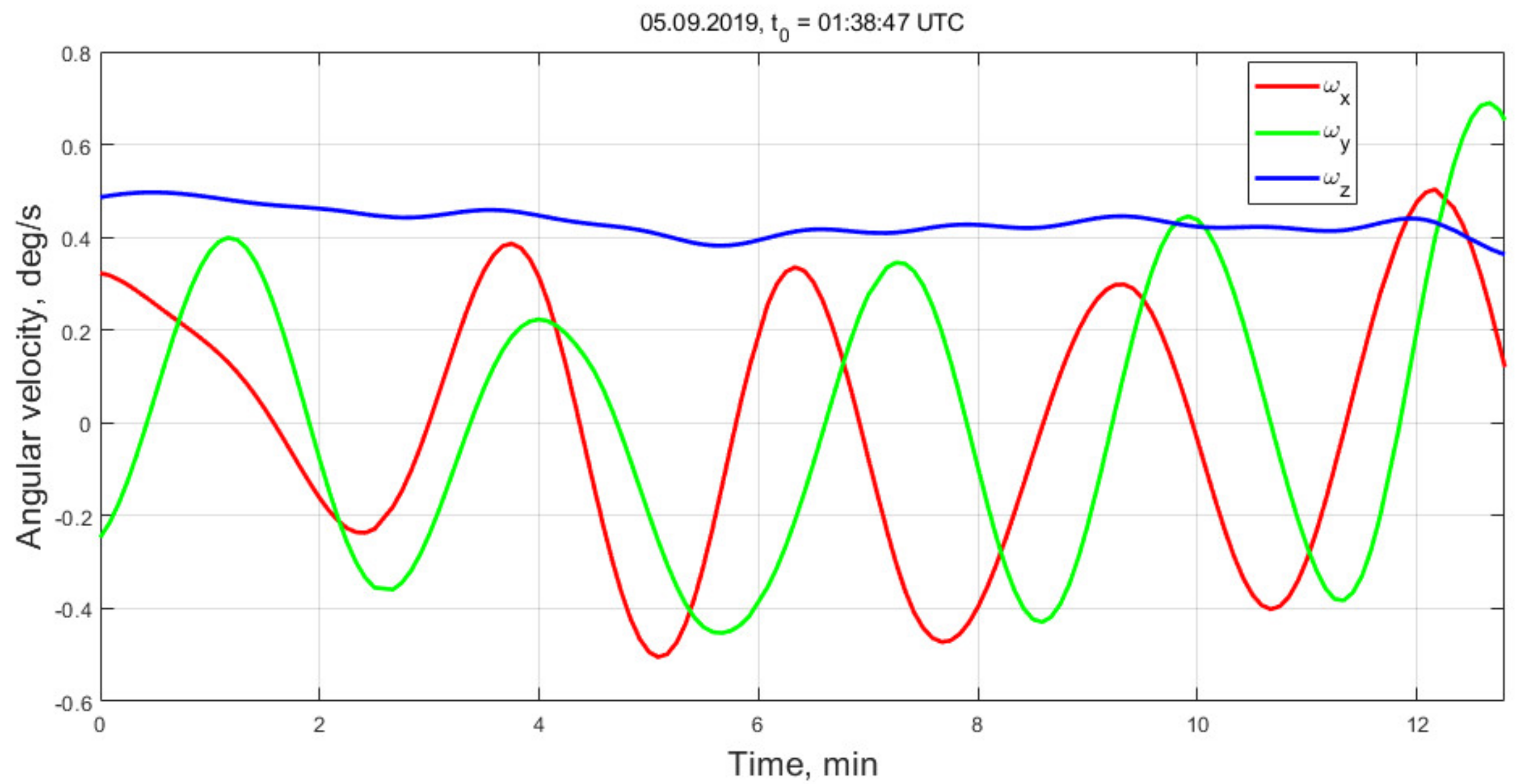
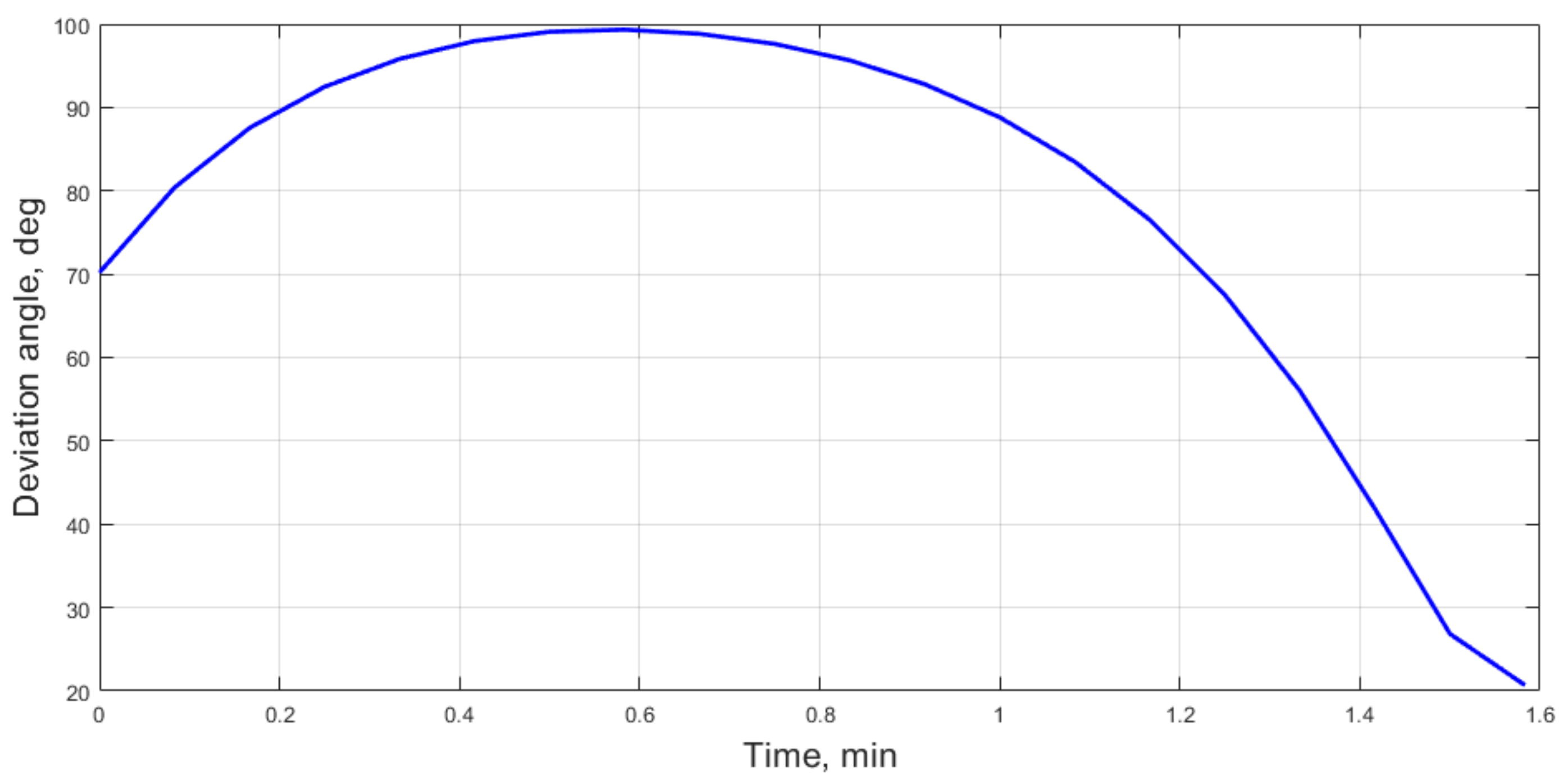
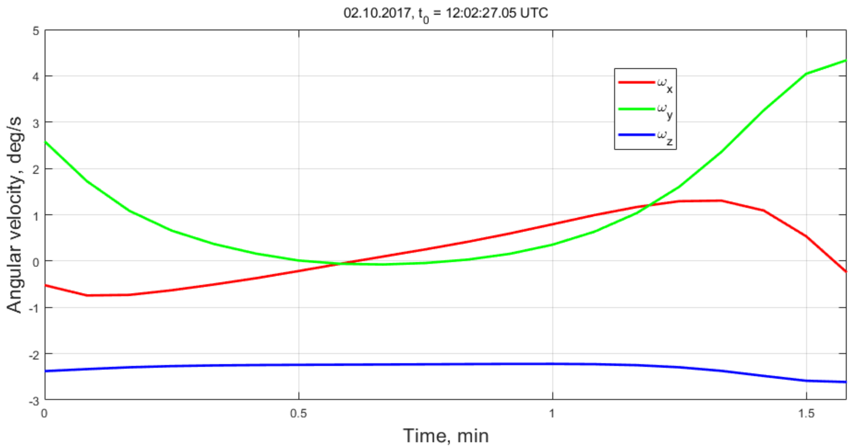
4.3. Transient Attitude Motion

The telemetry obtained on 20 August 2019 is considered below. The satellite altitude was 240 km, the average atmosphere density value is 4 × 10⁻¹¹ kg/m3. The aerodynamic torque value prevailed over the magnetic torque. The aerodynamic torque is strongly affected by the center of mass shift relative to the center of pressure. This displacement was included in the vector of the estimated parameters in the least squares method. The displacement estimation provided approximately 7 cm, along the longitudinal axis.
The satellite lost the magnetic stabilization on August. However, the aerodynamic stabilization was not achieved as indicated by Figure 14. The satellite rotation rate is relatively high as presented in Figure 15. This represents the transient motion from the magnetic to the aerodynamic stabilization. The aerodynamic torque is large enough to disturb the magnetic stabilization. However, the magnetic torque is still strong enough to prevent the aerodynamic stabilization.

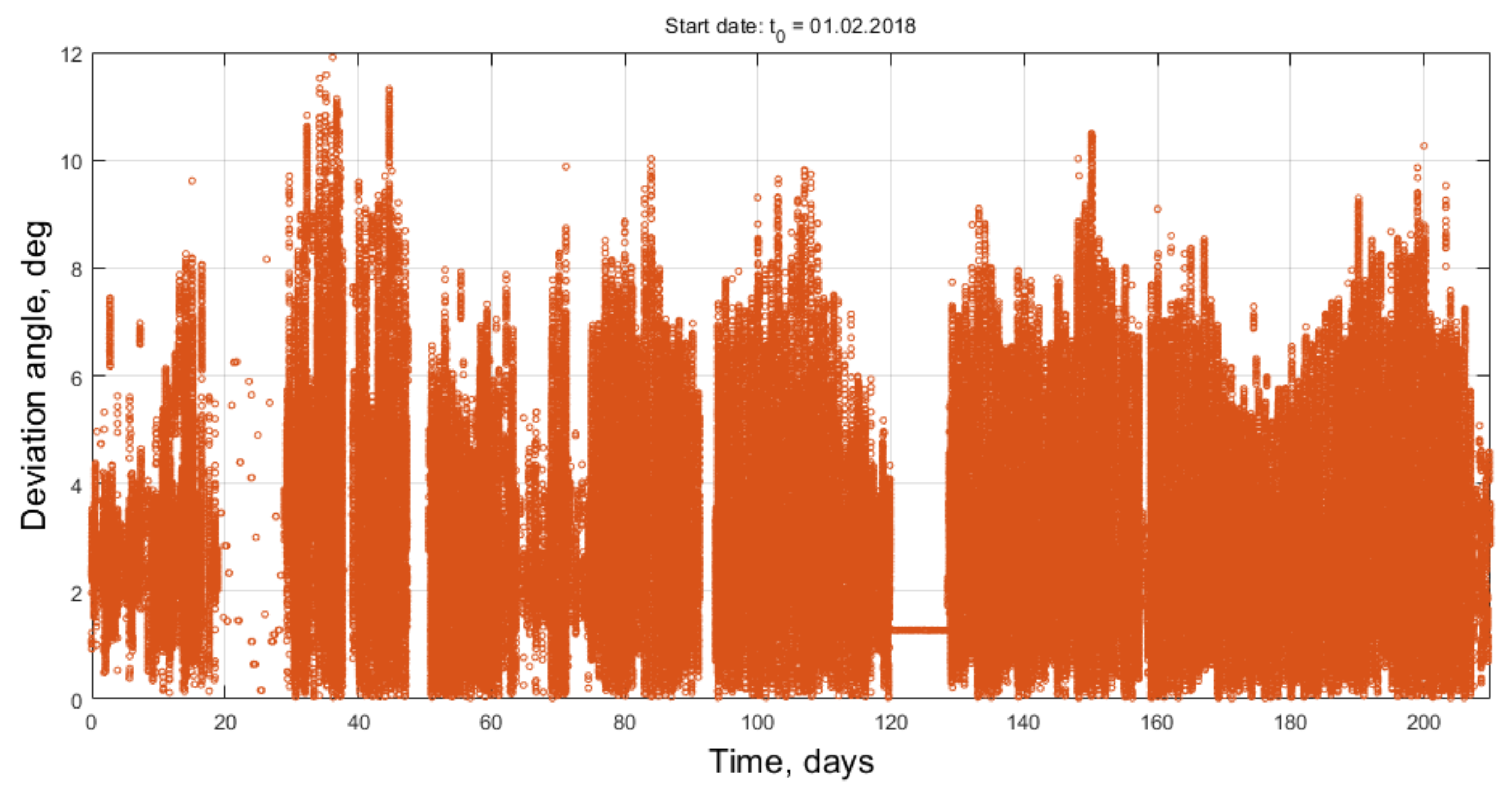
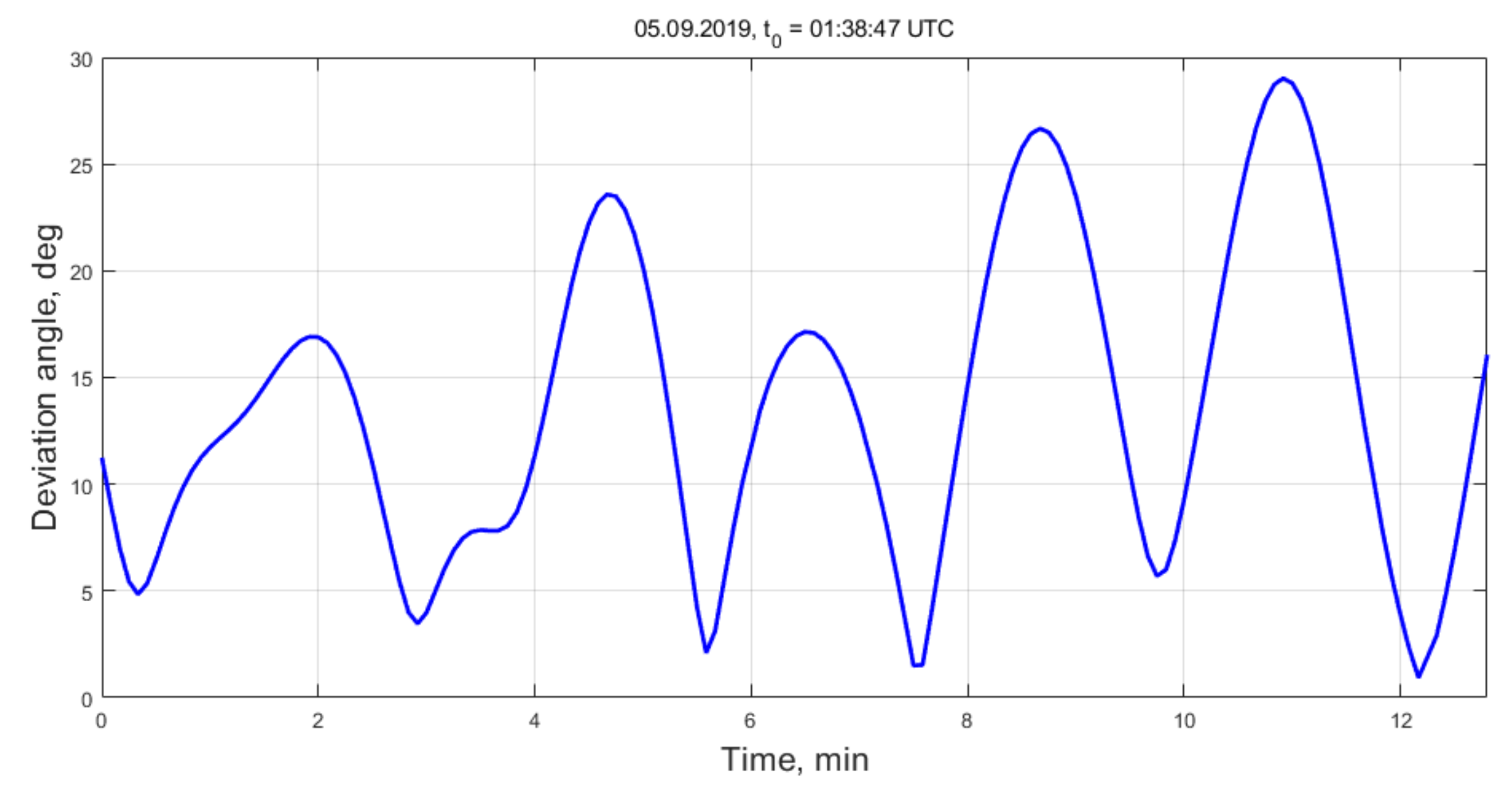
4.4. Aerodynamic Attitude Stabilization

The satellite exhibited the tumbling transient motion for about two weeks. The telemetry analysis for 5 September 2019 is provided below. The satellite altitude is approximately 180 km and the atmosphere density is 3 × 10⁻¹⁰ kg/m3. The aerodynamic torque is larger than the magnetic one by an order of magnitude. The deviation of the axis of the approximate dynamical symmetry from the direction of the incoming airflow does not exceed 30 degrees according to Figure 16. The angular velocity decreased to 0.5 deg/s (Figure 17) and a slow rotation around OZ axis is observed.

4.5. Tumbling During The Very Last Day

6 September 2019 was the last day of the mission. The satellite altitude was 153 km and the atmosphere density was 1.5 × 10⁻⁹ kg/m3. The satellite lost the aerodynamic stabilization, as seen in Figure 18 and Figure 19.
The satellite tumbling rate increased up to 5 degrees per second before the contact was eventually lost. The reason of this motion type cannot be established reliably but one of the reasons can be the loss of the hull integrity.

5. Conclusions

The attitude motion of TNS-0 #2 satellite was analyzed. The aerodynamic torque influence gradually increased compared to the magnetic torque due to the orbit decay in last months of the mission. This caused the transition from the passive magnetic stabilization of about 12 degrees of accuracy to the aerodynamic stabilization with the deviation from the incoming airflow of about 30 degrees. The communication via the GlobalStar satellites provided enough onboard sensor measurements for the attitude motion reconstruction up the altitude of 153 km, probably just before the breakdown of the satellite in the dense atmospheric layers.

Author Contributions

Data processing methodology, D.I.; manuscript preparation, D.R.; obtained data analysis, S.T.; data processing, Y.M. and S.S.; work coordination, M.O.; communication with satellite, telemetry preprocessing, I.F., N.Y., and A.S. All authors have read and agreed to the published version of the manuscript.

Funding

This research received no external funding.

Institutional Review Board Statement

Not applicable.

Informed Consent Statement

Not applicable.

Data Availability Statement

Not applicable.

Conflicts of Interest

The authors declare no conflict of interest.

References

  1. Ovchinnikov, M.Y.; Shargorodskiy, V.D.; Pen’kov, V.I.; Mirer, S.A.; Guerman, A.D.; Nemuchinskiy, R.B. Nanosatellite REFLECTOR: Choice of parameters of the attitude control system. Cosm. Res. 2007, 45, 60–77. [Google Scholar] [CrossRef]
  2. Sarychev, V.A.; Mirer, S.A.; Sazonov, V.V. Plane oscillations of a gravitational system satellite-stabilizer with maximal speed of response. Acta Astronaut. 1976, 3, 651–669. [Google Scholar] [CrossRef]
  3. Sarychev, V.A.; Gutnik, S.A. Gravity-oriented satellite dynamics subject to gravitational and active damping torques. Cosm. Res. 2018, 56, 68–74. [Google Scholar] [CrossRef]
  4. German, A.D.; Gutnik, S.A.; Sarychev, V.A. Satellite dynamics due to gravity and constant torques. J. Comput. Syst. Sci. Int. 2017, 56, 125–136. [Google Scholar] [CrossRef]
  5. Battagliere, M.L.; Santoni, F.; Ovchinnikov, M.; Graziani, F. Hysteresis Rods in The Passive Magnetic Stabilization System for University Micro and Nanosatellites. In Proceedings of the 59th IAC, Glasgow, UK, 29 September–3 October 2008; p. 10. [Google Scholar]
  6. Long, M.; Lorenz, A.; Rodgers, G.; Tapio, E.; Tran, G.; Jackson, K.; Twiggs, R.; Bleier, T. A Cubesat Derived Design for a Unique Academic Research Mission in Earthquake Signature Detection. In Proceedings of the 16th Annual/USU Conference on Small Satellites, Logan, TX, USA, 12–15 August 2002; p. 17. [Google Scholar]
  7. Tsuda, Y.; Sako, N.; Eishima, T.; Ito, T.; Arikawa, Y.; Miyamura, N.; Tanaka, A.; Nakasuka, S. University of Tokyo’s CubeSat Project-Its Educational and Technological Significance. In Proceedings of the 15th Annual AIAA/USU Conference on Small Satellites, Logan, TX, USA, 13–16 August 2001; p. 8. [Google Scholar]
  8. Battagliere, M.L.; Santoni, F.; Piergentili, F.; Ovchinnikov, M.; Graziani, F. Passive magnetic attitude stabilization system of the EduSAT microsatellite. Aerosp. Eng. 2010, 224, 1097–1107. [Google Scholar] [CrossRef]
  9. Hennepe, F.T.; Zandbergen, B.T.C.; Hamann, R.J. Simulation of the Attitude Behaviour and Available Power Profile of the Delfi-C3 Spacecraft with Application of the OpSim Platform. In Proceedings of the Paper at the 1st CEAS European Air and Space Conference, Berlin, Germany, 10–13 September 2007; p. 9. [Google Scholar]
  10. Burton, R.; Rock, S.; Springmann, J.; Cutler, J. Online attitude determination of a passively magnetically stabilized spacecraft. Acta Astronaut. 2017, 133, 269–281. [Google Scholar] [CrossRef] [Green Version]
  11. Miguel, N.; Colombo, C. Deorbiting spacecraft with passively stabilised attitude using a simplified quasi-rhombic-pyramid sail. Adv. Sp. Res. 2020, 67, 2561–2576. [Google Scholar] [CrossRef]
  12. Xuegang, Z.; Zhencai, Z.; Hongyu, C. Aerodynamic passive stabilization design and flight data analyses for transitional regime satellite LX-1. Acta Astronaut. 2020, 167, 232–238. [Google Scholar] [CrossRef]
  13. Sarychev, V.A.; Gutnik, S.A. Satellite dynamics under the influence of gravitational and aerodynamic torques. A study of stability of equilibrium positions. Cosm. Res. 2016, 54, 388–398. [Google Scholar] [CrossRef]
  14. Psiaki, M.L. Nanosatellite attitude stabilization using passive aerodynamics and active magnetic torquing. J. Guid. Control. Dyn. 2004, 27, 347–355. [Google Scholar] [CrossRef]
  15. Berthet, M.; Yamada, K.; Nagata, Y.; Suzuki, K. Feasibility assessment of passive stabilisation for a nanosatellite with aeroshell deployed by orbit-attitude-aerodynamics simulation platform. Acta Astronaut. 2020, 173, 266–278. [Google Scholar] [CrossRef]
  16. Ovchinnikov, M.; Ivanov, D.; Pansyrnyi, O.; Sergeev, A.; Fedorov, I.; Selivanov, A.; Khromov, O.; Yudanov, N. Technological NanoSatellite TNS-0 #2 Connected Via Global Communication System. Acta Astronaut. 2020, 170, 1–5. [Google Scholar] [CrossRef]
  17. Ivanov, D.S.; Ovchinnikov, M.Y.; Pantsyrnyi, O.A.; Selivanov, A.S.; Sergeev, A.S.; Fedorov, I.O.; Khromov, O.E.; Yudanov, N.A. Nanosatellite TNS-0 No.2 Attitude Motion After The Launch From ISS. Cosm. Res. 2019, 57, 272–288. [Google Scholar] [CrossRef]
  18. Thébault, E.; Finlay, C.C.; Beggan, C.D.; Alken, P.; Aubert, J.; Barrois, O.; Bertrand, F.; Bondar, T.; Boness, A.; Brocco, L.; et al. International Geomagnetic Reference Field: The 12th generation. Earth Planets Sp. 2015, 67, 79. [Google Scholar] [CrossRef]
  19. Sarychev, V.A.; Penkov, V.I.; Ovchinnikov, M.Y. Mathematical model of hysteresis based on magneto-mechanical analogy. Math. Simul. 1989, 1, 122–133. [Google Scholar]
  20. Ovchinnikov, M.Y.; Ivanov, D.S.; Ivlev, N.A.; Karpenko, S.O.; Roldugin, D.S.; Tkachev, S.S. Development, integrated investigation, laboratory and in-flight testing of Chibis-M microsatellite ADCS. Acta Astronaut. 2014, 93. [Google Scholar] [CrossRef]
  21. Ivanov, D.; Ovchinnikov, M.; Ivlev, N.; Karpenko, S. Analytical study of microsatellite attitude determination algorithms. Acta Astronaut. 2015, 116, 339–348. [Google Scholar] [CrossRef]
  22. Kim, O.-J.; Shim, H.; Yu, S.; Bae, Y.; Kee, C.; Kim, H.; Lee, J.; Han, J.; Han, S.; Choi, Y. In-Orbit Results and Attitude Analysis of the SNUGLITE Cube-Satellite. Appl. Sci. 2020, 10, 2507. [Google Scholar] [CrossRef] [Green Version]
  23. Beuselinck, T.; Van Bavinchove, C.; Abrashkin, V.I.; Kazakova, A.E.; Sazonov, V.V. Determination of attitude motion of the Foton M-3 satellite according to the data of onboard measurements of the Earth’s magnetic field. Cosm. Res. 2010, 48, 246–259. [Google Scholar] [CrossRef]
  24. Abrashkin, V.I.; Voronov, K.E.; Piyakov, Y.Y.; Sazonov, V.V.; Semkin, N.D.; Chebukov, S.Y. Attitude motion of the Photon M-4 satellite. Cosm. Res. 2014, 54, 315–322. [Google Scholar] [CrossRef]
  25. Abrashkin, V.I.; Voronov, K.E.; Piyakov, I.V.; Puzin, Y.Y.; Sazonov, V.V.; Semkin, N.D.; Chebukov, S.Y. Rotational motion of Foton M-4. Cosm. Res. 2016, 54, 296–302. [Google Scholar] [CrossRef]
  26. Kramer, A.; Bangert, P.; Schilling, K. UWE-4: First Electric Propulsion on a 1U CubeSat—In-Orbit Experiments and Characterization. Aerospace 2020, 7, 98. [Google Scholar] [CrossRef]
  27. Belokonov, I.V.; Kramlikh, A.V.; Lomaka, I.A.; Nikolaev, P.N. Reconstruction of a Spacecraft’s Attitude Motion Using the Data on the Current Collected from Solar Panels. J. Comput. Syst. Sci. Int. 2019, 58, 286–296. [Google Scholar] [CrossRef]
Figure 1. TNS-0 #2 nanosatellite (Credit: JSC Russian Space Systems).
Applsci 11 06784 g001
Figure 2. Center of mass location, permanent magnet, magnetometer and Sun sensors positions in the satellite body.
Applsci 11 06784 g002
Figure 3. The first measurements from the magnetometer.
Applsci 11 06784 g003
Figure 4. Measured geomagnetic field excluding bias.
Applsci 11 06784 g004
Figure 5. Measured and predicted unit vector of the geomagnetic field.
Applsci 11 06784 g005
Figure 6. Angular velocity components.
Applsci 11 06784 g006
Figure 7. Sun sensors normalized measurements and its predicted values.
Applsci 11 06784 g007
Figure 8. Angular velocity damping history.
Applsci 11 06784 g008
Figure 9. Deviation from the direction of the local magnetic field.
Applsci 11 06784 g009
Figure 10. Angular velocity in the steady-state motion.
Applsci 11 06784 g010
Figure 11. Deviation of OZ axis from the direction of the local magnetic field for 210 days starting from 1 February 2018.
Applsci 11 06784 g011
Figure 12. Altitude for the whole mission lifetime according to the onboard GPS/GLONASS receiver.
Applsci 11 06784 g012
Figure 13. Deviation of OZ axis from the direction of the local magnetic field.
Applsci 11 06784 g013
Figure 14. Deviation of OZ axis of the satellite from the flow direction.
Applsci 11 06784 g014
Figure 15. Estimated angular velocity.
Applsci 11 06784 g015
Figure 16. Deviation of OZ axis from the direction of the incoming air flow.
Applsci 11 06784 g016
Figure 17. Angular velocity in the body reference frame.
Applsci 11 06784 g017
Figure 18. Deviation of OZ axis from the direction of the incoming air flow.
Applsci 11 06784 g018
Figure 19. Angular velocity in the body reference frame.
Applsci 11 06784 g019
Publisher’s Note: MDPI stays neutral with regard to jurisdictional claims in published maps and institutional affiliations.

