Article

Design and Experimental Evaluation of an Electrorheological Haptic Module with Embedded Sensing

1
Department of Computer Science, University of Chicago, Chicago, IL 60615, USA
2
Department of Mechanical and Manufacturing Engineering, Miami University, Oxford, OH 45056, USA
3
Center for Mechanical Metrology, Korea Research Institute of Standards and Science, Daejeon 34113, Korea
4
Department of Electronic Engineering, Korea National University of Transportation, Chungju-si 27469, Korea
*
Author to whom correspondence should be addressed.
Submission received: 1 June 2021 / Revised: 19 August 2021 / Accepted: 19 August 2021 / Published: 22 August 2021
(This article belongs to the Special Issue Haptics: Technology and Applications2021)

Abstract

:
We present a miniature haptic module based on electrorheological fluid, designed for conveying combined stiffness and vibrotactile sensations at a small scale. Haptic feedback is produced through electrorheological fluid’s controllable resistive force and varies with the actuator’s deformation. To demonstrate the proposed actuator’s feedback in realistic applications, a method for measuring the actuator’s deformation must be implemented for active control. To this end, in this study, we incorporate a sensor design based on a bend-sensitive resistive film to the ER haptic actuator. The combined actuator and sensor module was tested for its ability to simultaneously actuate and sense the actuator’s state under indentation. The results show that the bend sensor can accurately track the actuator’s displacement over its stroke. Thus, the proposed sensor may enable control of the output resistive force according to displacement, which may lead to more informed and engaging combined kinesthetic and tactile feedback.

1. Introduction

The recent rise in accessible, consumer-grade virtual reality has increased demand for haptic devices that can enhance user experience. Haptic feedback provides a more immersive experience by stimulating users through an additional and often underutilized sensory channel: touch. The ability to feel and manipulate objects in an environment (real or virtual), such as feeling the stiffness of squeezing a tennis ball in one’s hand or feeling the opposing force of pushing open a heavy door, gives users a more realistic sensory experience. This is especially true when combined with the more common visual and auditory feedback [1,2]. Therefore, haptic feedback can benefit a variety of applications, including not only virtual reality, but also machine teleoperation, training tools and simulators, gaming, accessibility, and entertainment [3,4,5,6,7,8].
For example, commercial touchscreen devices use haptic actuators to provide vibrations to create eyes-free feedback that complements user input, such as vibrations during typing to emulate the feeling of a physical keyboard [9,10]. Vibrating actuators are capable of notifying users and even invoking haptic illusions [11,12,13], but they fall short of delivering truly realistic haptic feedback. To truly provide realistic haptic sensations, devices must be able to take full advantage of the wide sensory range afforded by our sense of touch. To do so, the combination of two feedback modalities is necessary: (1) tactile and (2) kinesthetic [14]. Tactile feedback is sensed by mechanoreceptors in the skin and provides information related to vibration, surface roughness, and textures [15,16]. Kinesthetic feedback is perceived as forces and torques by muscles, tendons, and joints, and provides information about position, movement, and force [17,18]. Therefore, when designing interfaces and interactions based on touch, both modes of haptic feedback should be present to convey realistic haptic sensations by covering the entire spectrum of human haptic perception.
Unfortunately, much of the research on new haptic devices focuses on presenting either kinesthetic or tactile feedback, rather than devices to provide both at once. The primary reason for this divide is that while miniature tactile actuators have been widely studied and commercialized, the development of miniature kinesthetic actuators has proven challenging because of physical limitations. Most of the kinesthetic devices proposed so far have adopted bulky commercial motors or pneumatic pumps to generate force feedback [19,20,21,22,23]. However, kinesthetic-scale motors and pumps are limited to tethered applications due to their large size and power draw.
To overcome the limitations of traditional actuators, actuators based on smart materials have been identified as an attractive alternative because of their tunable properties, mechanical simplicity, and conformability [24,25,26,27,28,29,30]. For example, piezoelectric actuators have been used to generate vibrotactile feedback [31,32]; however, the forces produced are too small to invoke kinesthetic sensations. Shape memory alloys, another smart material, can provide kinesthetic forces by bending and pulling, but their refresh time is not sufficiently fast to generate high frequency tactile sensations [33,34,35]. Additionally, shape memory alloys often introduce unwanted heat into the system, which may interfere with the intended haptic sensation. Thus, we identify a gap between these two materials’ properties: to achieve concurrent tactile and kinesthetic sensations, the ideal material must be capable of generating high forces at fast rates, as well as easy to control with a subtle stimulus. Under these criteria, smart fluids are an attractive candidate for their rapid, stable response and ability to generate high yield stresses through their tunable viscosity.
Magnetorheological (MR) fluid, one such smart fluid, has been the basis for numerous haptic devices [36,37,38,39,40]. Often these MR-based devices were designed to demonstrate the potential of MR fluid-based designs but would be challenging to scale down for personal electronics due to the limiting size of the electromagnetic coil needed to generate feelable forces. Yang et al. [41,42,43] addressed this challenge by engineering a button type device for providing congruent tactile and kinesthetic feedback in a sufficiently small form-factor for mobile devices. Similarly, Heo et al. [44] designed a miniature haptic knob based on MR fluids for providing torque feedbacks when twisted. Unfortunately, despite modeling and optimization, designing MR actuators still requires precise manufacturing to produce the miniature coil.
Electrorheological (ER) fluid has a field-dependent viscosity, much like MR fluid, but instead responds to applied electric fields, rather than magnetic fields. Similar to MR fluid, ER fluid-based devices feature fast response times, low power consumption, and stability. However, ER fluid relies on simpler electrical control; only two electrodes spaced approximately 1 mm apart are required. When compared to a coil, the electrode form factor enables thinner, more mobile designs [45,46,47]. Past works have investigated ER fluid for its ability to convey haptic feedback [48,49,50,51]. However, previous studies have rarely focused on device miniaturization or providing combined tactile and kinesthetic feedback. Mazursky et al. [52] demonstrated a thin, button-type actuator based on ER fluid. Designing button-type actuators has long been studied in human–computer interaction, but often requires combining separate actuators for each sensation or convincing the user of displacement through haptic illusions [53,54,55]. In contrast, using smart fluids enables a single mechanism for providing both sensations. Subsequent studies improved the design by activating the fluid in both squeeze and flow modes, resulting in a wide range of forces (2.4–6.2 N at maximum depth) and frequencies across the spectrum of human perception (0–300 Hz) [56,57]. Furthermore, the device measured only 6 mm thick, making it a feasible prototype for mobile designs.
To demonstrate this actuator in real-world applications, such as haptic rendering of compliant objects, a method of sensing the actuator’s state is necessary to incorporate control of the sensation with respect to pressed depth [58]. In other words, incorporating a sensing capability of the ER actuator to measure the displacement of the actuator’s contact surface is critically important to control the actuator’s force output with respect to the user’s finger position. Thus, the primary goals of this study are to embed a bending-sensitive sensor within a haptic button actuator based on ER fluid, where sensations are generated from fluid flow through charged electrodes due to the user’s press, and to experimentally evaluate the ER haptic module with the embedded sensor. In the following sections, we first detail the design of the proposed haptic module consisting of an electrorheological haptic actuator with an embedded depth sensor to provide controllable feedback during indentation, creating a tunable button. We evaluate the performance of the module by first characterizing the sensor’s bend-sensitive resistance. Then, we mechanically test the module’s combined sensing and actuation performance and assess the module’s ability to provide various haptic force profiles.

2. Design and Characterization of the Haptic Module

The design of the haptic device is driven by a goal of closing the loop on actuation by integrating a sensor into the device to enable more intelligent control. In the following subsections, we first detail the actuator’s design and working principle, which acts as a button with tunable indentation profiles based on ER fluid’s controllable viscosity. Then, we introduce the sensor’s design, working principle, and integration into the haptic module. Finally, we characterize the bending sensor’s resistance with respect to bend angle.

2.1. Design and Working Principle of Miniature ER Actuator

A prototype ER actuator capable of generating both tactile and kinesthetic sensations was engineered in an earlier study by authors. While detailed design and experimental results of the prototype actuator can be found in the study by Mazursky (2020), this section intends to recollect the working principle of the ER actuator and its key performance as background information in the context of the current study. Particularly, understanding the dynamic force behaviors of the actuator would be useful for comprehending the experimental results of the actuator with the embedded sensor.
Figure 1 illustrates the form factor and working principle of the cylindrical ER actuator. When a user presses upon the membrane surface, the grounded spring electrode is displaced vertically, squeezing the fluid between the grounded spring electrode and high voltage electrode (i.e., squeeze mode, shown in red in Figure 1). Due to the pressure gradient from the press, fluid flows radially outward through parallel electrodes fixed in place (i.e., flow mode, shown in blue in Figure 1). Hence, the actuator operates in both squeeze and flow modes. To compensate for the change in volume due to pressing, the actuator features radial slots allowing the membrane between the slots to deform elastically, forming a reservoir (see Figure 1b). Upon releasing the press, the reservoir lowers, and the actuator returns to its pre-pressed state due to the electrode spring and membrane’s elasticity. When a voltage is supplied to the electrodes, the ER fluid’s suspensions form fibrous networks parallel to the field lines between the electrodes. This microstructural transformation results in yield stress with a magnitude corresponding to the applied field strength. Therefore, the force felt by the user’s finger while pressing is a function of the applied voltage. As the magnitude of the voltage increases, the force required to cause the fluid to flow increases, providing a controllable range of kinesthetic feedback. By introducing a frequency to the applied voltage, the resistive force may fluctuate, resulting in various tactile feedback responses. Thus, the user may feel a dynamic range of simultaneous kinesthetic and tactile sensations.
Table 1 presents the actuator’s key dimensions and material properties. Notably, the actuator measures only 6 mm thick and 42 mm in diameter, making it relatively small compared to equivalent kinesthetic devices. The gap between the spring electrode and HV electrode is initially 1.3 mm. The actuator may be pressed to a maximum depth of 1 mm, reducing this gap to 0.3 mm. The fixed electrodes are spaced at 1.8 mm apart. The membrane consists of two layers. The contact layer is made of a PDMS film and is adhered to the structure by acrylic tape (3M™ VHB 4910, MN, USA). The actuator’s internal volume is filled with 2 mL of giant electrorheological (GER) fluid (Smart Materials Laboratory Ltd., Kowloon, Hong Kong), a type of ER fluid that exhibits a high yield stress nearly an order of magnitude greater than that of conventional ER fluids [59,60].
Figure 2 illustrates the haptic capabilities of the actuator by measuring the force generated over the actuator’s indentation under different excitation signals. As shown, the actuator has a maximum indentation depth of 1 mm. Figure 2a presents the actuator’s kinesthetic output. As the applied voltage increases, the resistive force increases due to the fluid’s increasing yield stress. With no voltage applied, the maximum force posed by the actuator was found to be 2.7 N at maximum depth. The maximum force produced by the actuator was about 6.2 N under a 4 kV load. These forces are sufficiently large to give many distinguishable levels of feedback to users based on the stiffness just-noticeable-difference [61]. Additionally, as shown in Figure 2b, introducing a frequency (i.e., 5 Hz sine wave as shown) to the applied signal results in tunable levels of tactile feedback.
However, prior work only evaluated the actuator as an open-loop device; the actuator provided haptic output, but without any sense of the provided input. Thus, the focus of this article is to develop a combined actuation and sensing module to provide closed-loop haptic feedback. By closing the loop, the actuator may provide controllable haptic feedback with respect to depth, such as emulating the click of a button at a specific pressed depth. Therefore, the module may provide more granular feedback, resulting in a more capable interface.

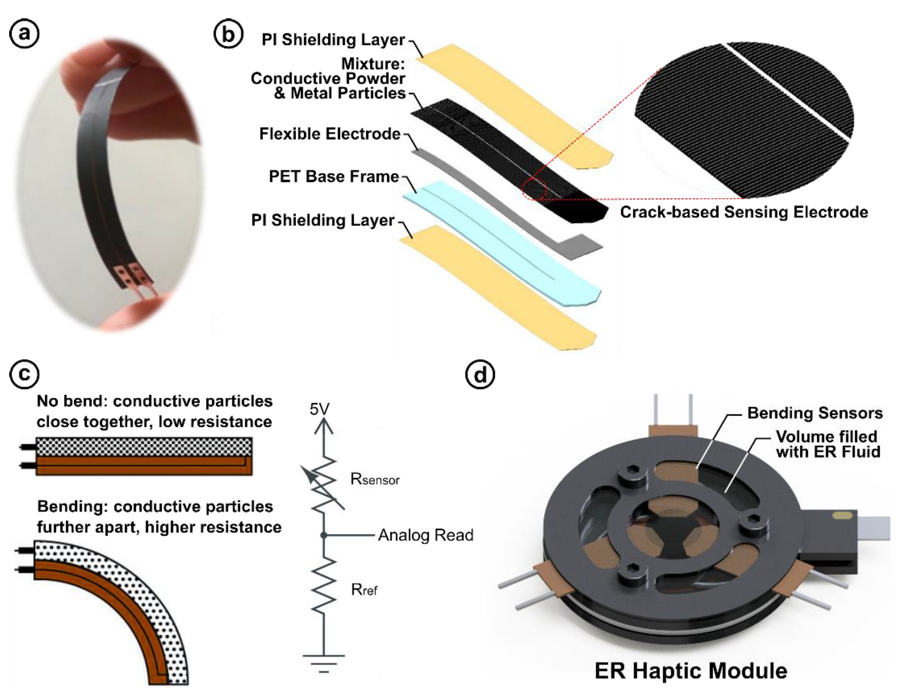
2.2. Working Principle and Implementation of the Bending Sensor

To demonstrate the haptic actuator as a more robust haptic interface that communicates digital information between the haptic device and a computer or microcontroller, the actuation loop must be closed. To control the output signal (resistive force and vibration frequency) of the haptic actuator based on the input (speed and position of the actuator’s indentation), a sensor must be introduced into the actuator’s design. To this end, we place a bending sensor on top of the membrane design, as shown in Figure 3. The sensor operates as a bend-sensitive resistor coupled to the membrane’s deformation to track its indentation. The sensor’s working principle is based on its strain-sensitive resistance. As shown in Figure 3b, the sensor is made from a flexible substrate doped with conductive particles. The sensor consists of multiple thin layers. The polyimide (PI) shielding layer protects the sensor from external noise from the nearby high voltage. The polyethylene terephthalate (PET) base frame provides structural support for the sensor to bend elastically. The flexible electrode, which is coated with a polymer-based ink dispersed in a mixture of metal particles and carbon black powder, is used to pass voltage through the conductive layer. To make the flexible electrode work as a bend-sensitive resistor, the fabricated sensor was bent excessively on a curved surface to create initial nanoscale cracks between the metal particles in the electrode [62,63]. The nanoscale cracks between metal particles formed on flexible electrodes enable variable conductivity between adjacent crack junctions depending on the degree of external bending. Here, the carbon black power forms electrically weak interconnections between the cracks in the metal powders, preventing complete electrical separation during bending.
Figure 3c shows the working principle of the sensor at macroscale. When the sensor is not bent, the particles are packed closely together giving rise to greater conductivity and lower resistance. When the sensor is bent, the conductive particles are spread farther apart, thereby increasing the resistance. By placing the sensor in a voltage divider circuit (see Figure 3c) and probing the output voltage with a microcontroller, the indentation depth may be tracked by a computer in real-time and fed into a control system. The module was designed such that three sensors may be placed within the actuator to track the indentation to ensure additional accuracy against interference from the actuator’s high voltage, as shown in Figure 3d. Moreover, a low-pass software filter was applied to the sensor’s analog data stream to reduce noise introduced by the high voltage line.
To characterize the proposed sensor’s resistance with respect to bend angle, a testing platform was constructed, as shown in Figure 4. The sensor was fixed to the stationary base and the sensor tip was magnetically secured to a platform attached to a stepper motor. As the motor turns, the sensor bends. At each angle, the sensor’s resistance is read using an analog input.
Figure 5 shows the characterization curve for the bending sensor: resistance (kΩ) vs. bending angle (deg). As shown, for positive angles (i.e., expansion), the sensor exhibits a nearly linear response from about 250 kΩ at 0 deg to 850 kΩ at 90 deg. Across the angles tested, the sensor elastically returns to its initial state. Thus, the sensor is predictable and may be integrated into our haptic module.

3. Evaluation of the Haptic Module
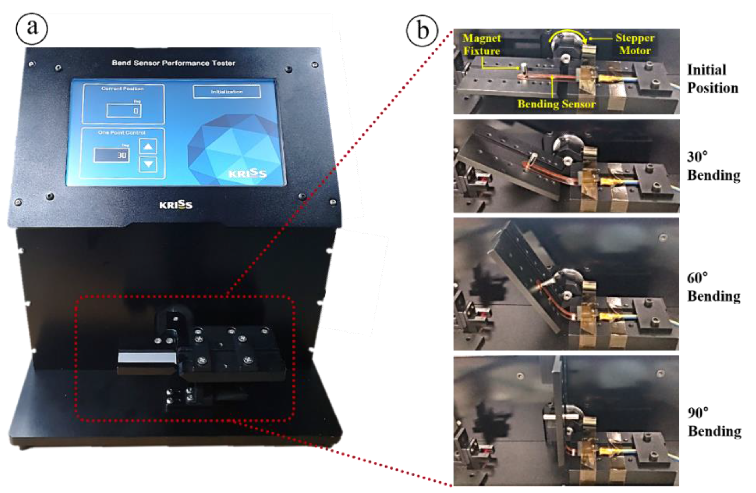
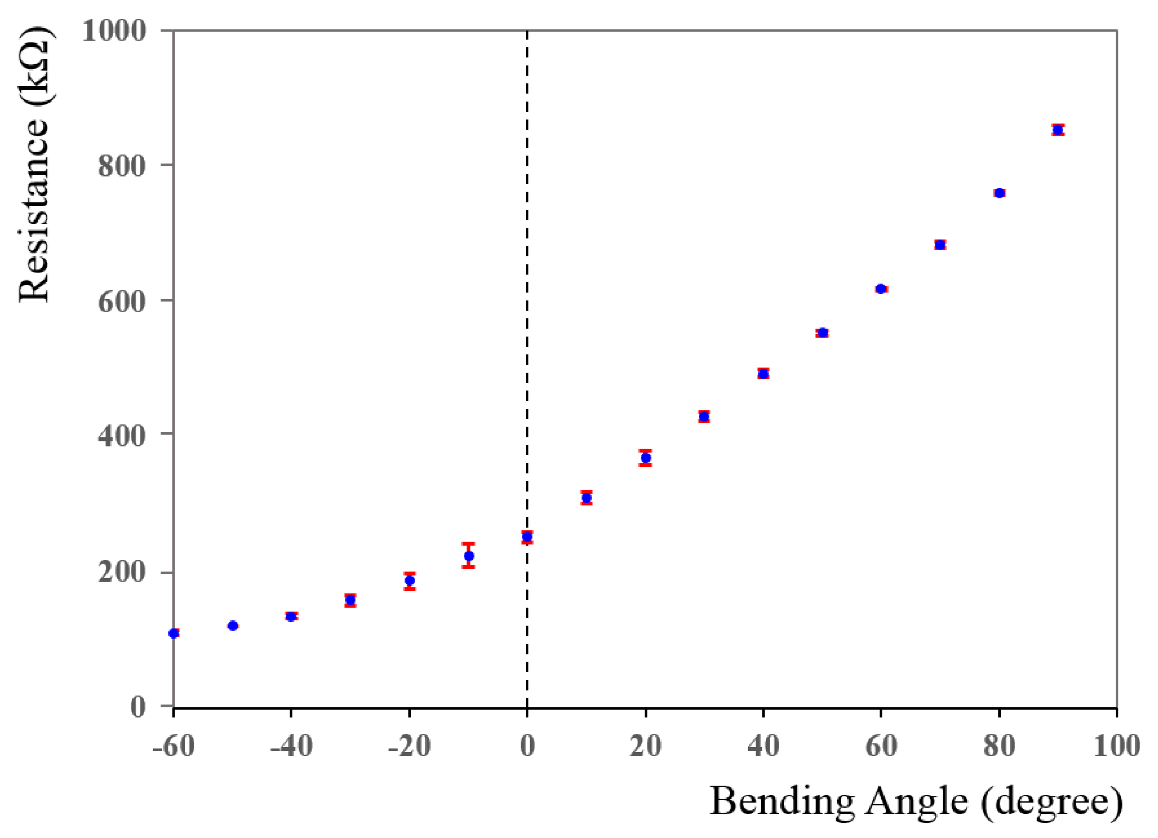
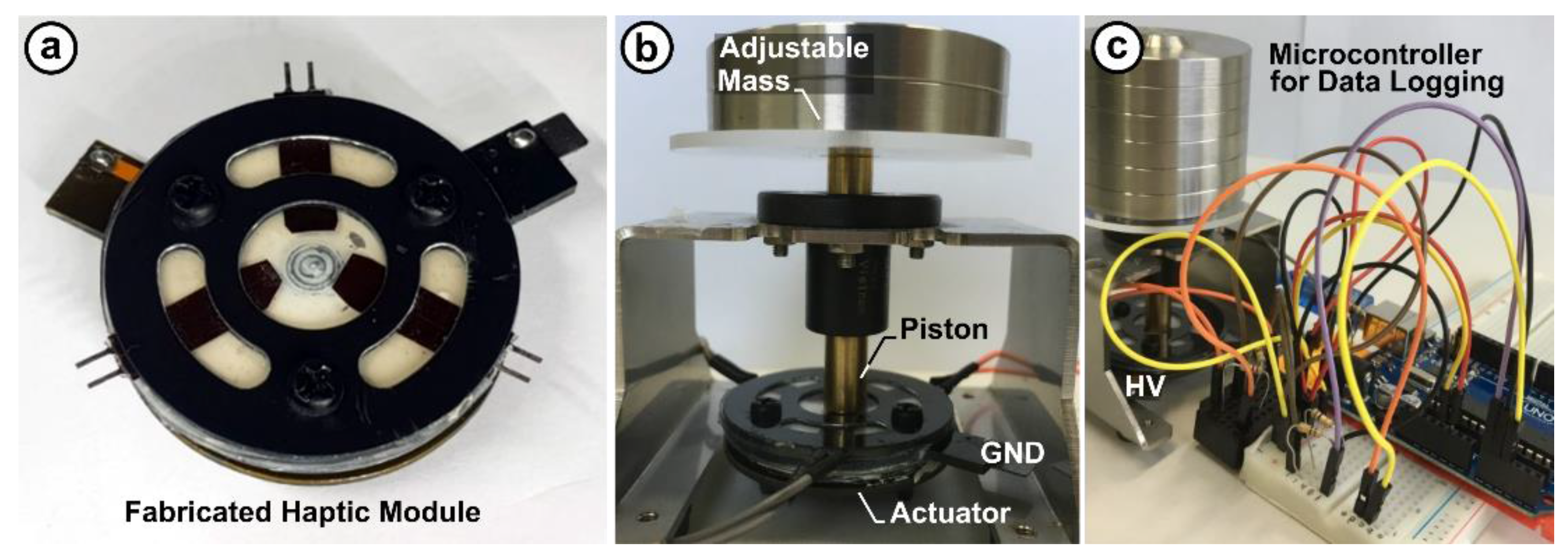
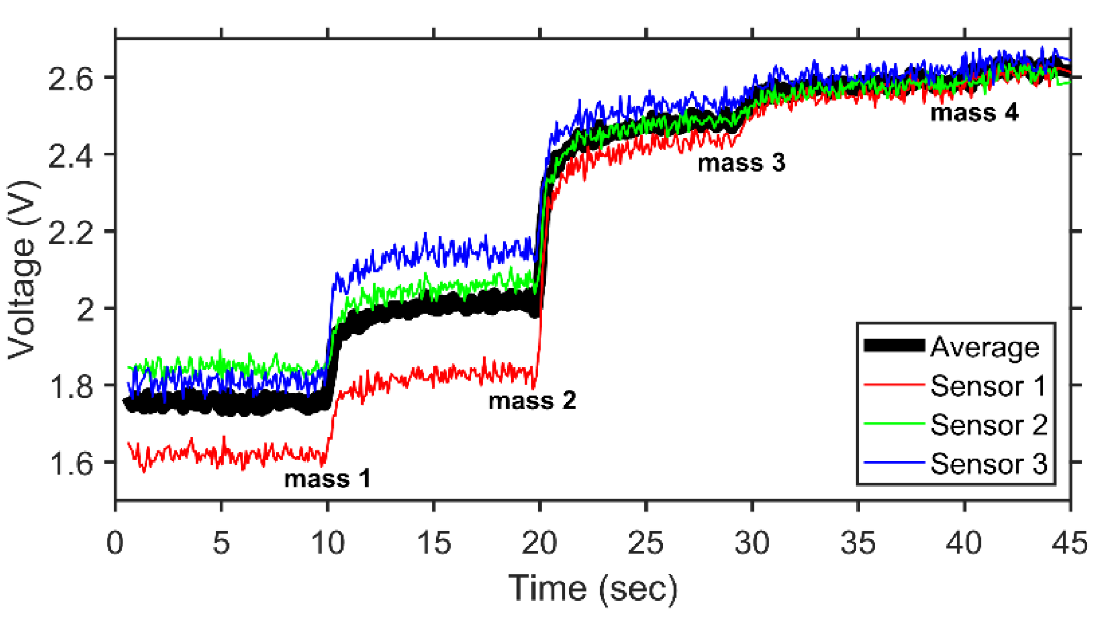
Having characterized the bending sensor and finding it to have stable performance in isolation, we now integrate it into our haptic module and evaluate the entire system’s performance. The following subsections detail the module’s performance under static and dynamic conditions.

3.1. Static Testing

Figure 6 shows the test platform that was constructed to first evaluate the actuator under static loads. Figure 6a shows a photo of the ER haptic module embedded with three bending sensors. The sensors are 120 degrees apart in a radial arrangement to increase the accuracy of the displacement reading. As shown in Figure 6b, the haptic module was held in place and a piston was used to press an adjustable mass the against the actuator’s contact surface. By stacking masses on top of the piston, the applied static pressure may be controlled. As the pressure increases, the piston presses the actuator’s surface deeper. Four masses were used to discretely step up the indentation depth, which was measured by the bending sensor. Using the Arduino setup shown in Figure 6c, the output voltage of the sensors was collected and processed to determine and log the actuator’s displacement. In the voltage divider circuit, 5 V was used as the supply voltage and a 100 kΩ resistor was used as the reference resistor. During this test, a sine wave (±4 kV, 3 Hz) was applied to excite the actuator.
Figure 7 shows the measured voltage across the sensor with respect to time. Each mass weighed 107 g and additional mass was added at 10 s intervals. Each individual sensor’s reading was logged, together with the average reading. As shown, the sensors had a small degree of variance across their readings. This may be attributed to the piston head not covering the module’s entire contact area and therefore not evenly applying pressure to all three bending sensors. However, as more mass is added, the readings from each sensor begin to converge. This is likely a result of how the piston displaces the module’s contact area. Initially, a lower mass only displaces the contact area directly below the piston. As the displacement grows larger, the displacement area also increases because of the elastic properties of the actuator. With enough mass, the entire contact area will displace, resulting in all three bending sensors equally reading the displacement. In addition, the voltage output reaches a maximum after sufficient mass is added to fully depress the piston to the bottom of the actuator. However, it is important to note that the discrepancy in sensor readings reflects what would be expected from real-world interaction, where a user does not necessarily press directly at the center of the module every time. Therefore, taking the average of the three sensors provides sufficient redundancy. As shown, the sensors can accurately respond to changes in the applied mass, and thus the indentation depth.

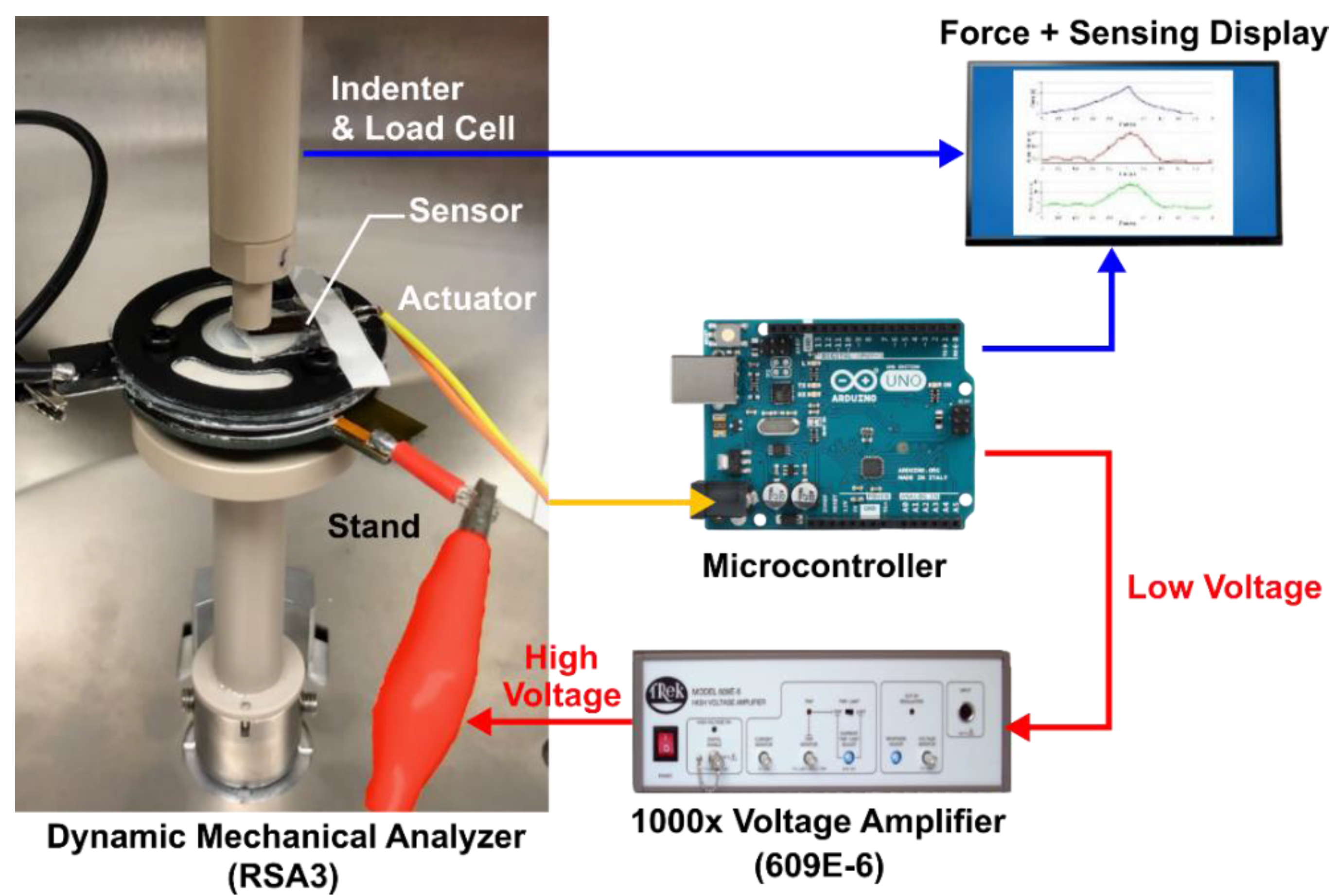
3.2. Dynamic Testing: Experimental Setup

Finally, to evaluate the performance of the complete prototype haptic module, mechanical analysis was conducted using a dynamic mechanical analyzer (RSA3, TA Instruments). Figure 8 shows the complete experimental setup. This experimentation measured the total resistive force with respect to indentation depth over the button’s stroke of up to 1 mm. In all testing, a constant indentation rate of 1 mm/s was used as an approximation of a typical human press. By holding the press depth and rate constant, we focus our analysis solely on the actuator’s field-dependent response [64]. We used an indentation tool similar in size to that of a human finger. We used an Arduino Uno to log the sensor readings and to control the actuator’s feedback via the applied frequency and voltage (stepped up from low voltage to high voltage by a Trek Model 609E-6, 1000V/V).

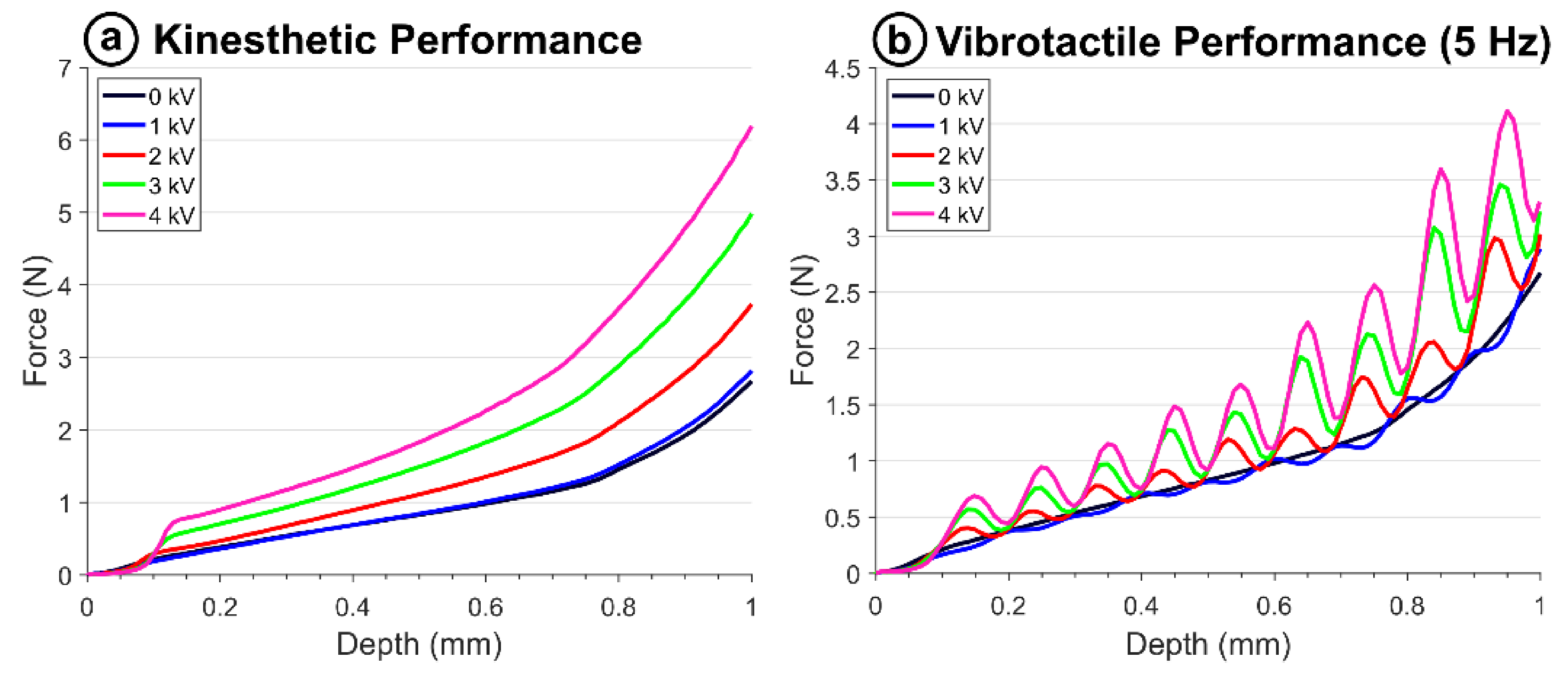
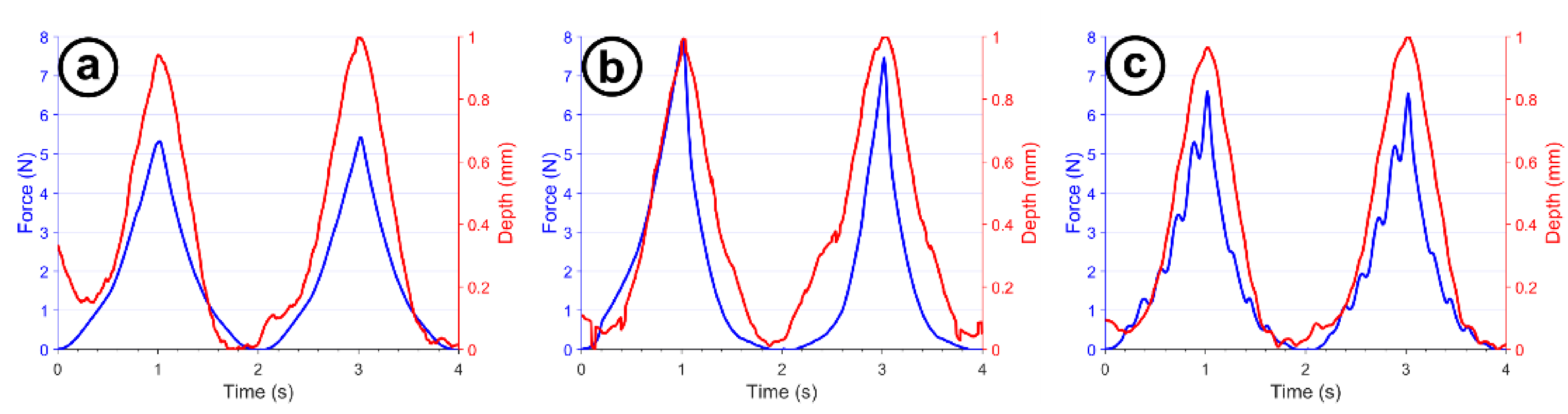
3.3. Dynamic Testing: Experimental Results

Our first test examined the sensor’s ability to accurately track the indenter during the press. Figure 9 shows the force generated by the actuator overlayed with the depth tracked by the sensor over time. Depth was determined by linearly mapping the sensor’s maximum and minimum readings to 0 and 1 mm, respectively, as enabled by the sensor’s linear response to bending. Three excitation signals were used: (a) 0 kV, i.e., off-state; (b) 4 kVDC; and (c) ± 4 kV sine wave at 3 Hz. As shown, two indentations were performed (i.e., the actuator was compressed and released two times); these results indicate that the sensor is effective at following indentation depth across multiple loading cycles and excitation conditions. Furthermore, adding the sensor does not significantly impede upon the generated kinesthetic and tactile sensations, as evidenced by the increased peak forces in the 4 kVDC condition and the oscillations present in the force curve for the sinusoidal condition.
Having found the sensor to be dynamically accurate, we look now to use it to inform our controller for actuator output. The added sensor can be used to programmatically switch the actuator’s response on and off, as shown in Figure 10. Here, we program turning on the high voltage (2, 3, and 4 kV) at 0.6 mm into the stroke (see Figure 10a). As shown in Figure 10b, when the voltage was switched on, the force curve’s slope increased according to the magnitude of the applied voltage, where increased voltage resulted in increased force. To best examine the electrorheological effect, Figure 10c isolates the force due to the fluid’s viscosity change from the total force by subtracting the actuator’s passive resistance, i.e., the actuator’s force–displacement curve when no voltage is applied. As shown, the force due to the ER effect rises rapidly at 0.6 mm when the high voltage is switched on. For the 2 kV applied voltage, the applied voltage triggered about 0.4 N maximum due to the ER effect. For 3 kV, about 0.7 N was generated. The greatest effect was observed for 4 kV, which produced about 1.1 N at maximum depth. This type of switching response can be used to emulate a button that has “bottomed out” or contacted a spring, causing the button’s stiffness to increase significantly.
To determine whether these changes in force are perceivable to end users, the performance must be compared to a perception threshold known as the just-noticeable-difference (JND). The JND denotes the degree to which a stimulus must change to be noticed by a user. In the case of a change of stiffness, the metric used for the JND is the force rate. The force rate is defined as the ratio of the difference between the maximum (the force output with voltages applied) and the minimum (i.e., the force output with 0 kV applied) force to the maximum force. The threshold for which humans can reliably feel changes in force is known to be about 7–10% for forces between 0.5 and 200 N [61]. Figure 10d shows the force rates across the actuator’s stroke for each voltage step. As shown, when the step-on voltage switches on at 0.6 mm, the force rate increases for all voltages, where the 4 kV excitation resulted in the highest peak force rate of about 25%. All curves peak above the 7–10% threshold, indicating that the stiffness change because of the voltage being stepped on is noticeable to end users.
Furthermore, the sensor can be used to switch the actuator response on and off rapidly, as shown in Figure 11. Here, we prescribe pulsing high voltage (2, 3, 4 kV) on at 0.6 mm and off shortly after (~25 ms, illustrated in Figure 11a; ER fluid has a response rate of ~5 ms [65], so this is sufficient to get a complete change in pressure). Figure 11b shows the actuator’s response to the step input. As shown, when the voltage pulse is applied at 0.6 mm depth, the slope of the force curves increases. As expected, the response is greatest with greater voltage. To best examine the electrorheological effect, Figure 11c isolates the force due to the fluid’s viscosity change from the total force by subtracting out the actuator’s passive resistance, i.e., the actuator’s force–displacement curve when no voltage is applied. As shown, the force due to the ER effect rises rapidly at 0.6 mm when the voltage pulse is applied. For the 2 kV applied voltage, the pulse triggered about 0.6 N due to the ER effect, whereas for 4 kV, about 0.8 N was generated. By closing the loop, the module can determine when to provide a pulse, for example, to emulate the clicking sensation of a tactile button [53].
Again, to find whether the change in stiffness resulting from the pulse excitation is noticeable can be determined using the JND. Figure 11d shows the force rates across the actuator’s indentation for each pulsed voltage. As shown, when the voltage pulse triggers at 0.6 mm, the force rate increases for all voltages, where the 4 kV excitation resulted in the highest peak force rate of about 31%. All curves peak above the 7–10% threshold, indicating that the stiffness change because of the voltage being stepped on is noticeable to end users.
Finally, to demonstrate controlling the actuator’s output over the entire indentation, we map the depth to the actuation frequency of an applied 4 kV square wave, as shown in Figure 12. At 0 mm depth, the frequency is set to 5 Hz. Over the 1 mm stroke, the frequency increases linearly to 10 Hz, as shown in Figure 12a. The actuator’s response is presented in Figure 12b. As shown, the force–depth curve contains oscillations that increase in frequency with respect to depth, as programmed. To best see this effect, we again isolate the force due to the ER effect from the total force by removing the off-state response from the signal, shown in Figure 12c. As seen in the plot, the output frequency was effectively mapped to depth using the proposed sensor and control method. This result demonstrates the module’s potential to take in an arbitrary control signal with respect to depth and render it as combined kinesthetic and tactile sensation when pressed by a user.

4. Conclusions

This article presents a closed-loop haptic module based on the tunable viscosity of ER fluids. By combining an ER haptic actuator with a bending sensor, a method for controlling the desired actuation force over the actuator’s stroke is possible. In our experiments, we characterized our custom bending sensor and found it to have a nearly linear response with respect to bend angle, making it suitable for sensing the state of the actuator’s indentation. In subsequent studies, we tested the sensor’s static and dynamic response when embedded in the actuator. We investigated the haptic module’s ability to give controlled outputs with respect to indentation depth. Specifically, we examined the system’s ability to present tactile pulses, kinesthetic step-on, and mapping the frequency sensation to the pressed depth. The results of these studies indicate that the module can offer controllable haptic sensations. This work may lead to a haptic interface that can render both tactile and kinesthetic sensations while maintaining a compact form factor. We envision this being used to produce numerous effects (for example, rendering the stiffness and tactile properties of different deformable materials) in haptic applications, such as games, mobile devices, and simulations. To achieve haptic sensations beyond the simple outputs presented in this study, a control scheme that better accounts for the device’s nonlinearity together with the unpredictable behaviors of real users is necessary [66,67,68,69]. Additionally, we acknowledge that our sensor design is one of many techniques that may be used to detect the actuator’s state, such as pressure-sensitive films directly integrated into the membrane’s PDMS [70,71] or flow sensors within the device itself [72,73]. In addition to the proposed strain sensor, which tracks the interface’s input, i.e., pressed depth, future work may incorporate a stress sensor to also monitor the device’s force output in real-time.
Traditionally, within the field of haptics, providing simultaneous kinesthetic and tactile feedback would require combining two different actuators, such as a motor or linear actuator and a linear resonant actuator, eccentric rotating mass, or piezoelectric motor. The fast response time and controllable resistive force offered by smart fluids enable both modes of feedback in a single package, such as the ER actuator presented in this article. We believe that smart materials and structures may continue to contribute to the future of haptic interfaces, but future work will require additional engineering to further miniaturize the footprint of control electronics to enable more mobile applications. Additionally, drawing from advances in soft electronics and sensors may lead to more wearable use cases.

Author Contributions

Conceptualization, J.-H.K. and T.-H.Y.; methodology, A.M. and J.-H.K.; software, A.M.; validation, T.M. and S.-Y.W.; formal analysis, A.M. and J.-H.K.; investigation, A.M., J.-H.K., T.M., S.-Y.W., and T.-H.Y.; resources, J.-H.K., S.-Y.W., and T.-H.Y.; data curation, A.M.; writing—original draft preparation, A.M.; writing—review and editing, A.M. and J.-H.K.; visualization, A.M. and T.M.; supervision, J.-H.K. and T.-H.Y. All authors have read and agreed to the published version of the manuscript.

Funding

This work was supported by Institute for Information and Communications Technology Promotion (IITP) grant funded by the Korea government (MSIT, Grant No. 2020-0-00003, Development of high piezoelectric coefficient composite and ultra-low power multilayered piezoelectric sensor/actuator multi-functional module).

Institutional Review Board Statement

Not applicable.

Informed Consent Statement

Not applicable.

Data Availability Statement

Not applicable.

Acknowledgments

The authors would like to thank the Ohio Space Grant Consortium for providing a fellowship to a student author.

Conflicts of Interest

The authors declare no conflict of interest. The funders had no role in the design of the study; in the collection, analyses, or interpretation of data; in the writing of the manuscript, or in the decision to publish the results.

References

  1. Culbertson, H.; Schorr, S.B.; Okamura, A.M. Haptics: The Present and Future of Artificial Touch Sensation. Annu. Rev. Control Robot. Auton. Syst. 2018, 1, 385–409. [Google Scholar] [CrossRef]
  2. Srinivasan, M.A.; Basdogan, C. Haptics in Virtual Environments: Taxonomy, Research Status, and Challenges. Comput. Graph. 1997, 21, 393–404. [Google Scholar] [CrossRef]
  3. Coles, T.R.; Meglan, D.; John, N.W. The Role of Haptics in Medical Training Simulators: A Survey of the State of the Art. IEEE Trans. Haptics 2011, 4, 51–66. [Google Scholar] [CrossRef]
  4. Eid, M.A.; Al Osman, H. Affective Haptics: Current Research and Future Directions. IEEE Access 2016, 4, 26–40. [Google Scholar] [CrossRef]
  5. Hayward, V.; Astley, O.R.; Cruz-Hernandez, M.; Grant, D.; Robles-De-La-Torre, G. Haptic Interfaces and Devices. Sens. Rev. 2004, 24, 16–29. [Google Scholar] [CrossRef]
  6. Jeong, J.-H.; Kim, Y.-M.; Lee, B.; Hong, J.; Kim, J.; Woo, S.-Y.; Yang, T.-H.; Park, Y.-H. Design and Evaluation of Enhanced Mock Circulatory Platform Simulating Cardiovascular Physiology for Medical Palpation Training. Appl. Sci. 2020, 10, 5433. [Google Scholar] [CrossRef]
  7. Laycock, S.D.; Day, A.M. Recent Developments and Applications of Haptic Devices. Comput. Graph. Forum 2003, 22, 117–132. [Google Scholar] [CrossRef]
  8. Schneider, O.; Shigeyama, J.; Kovacs, R.; Roumen, J.; Marwecki, S.; Boeckhoff, N.; Gloeckner, D.A.; Bounama, J.; Baudisch, P. DualPanto: A haptic device that enables blind users to continuously interact with virtual worlds. In Proceedings of the 31st Annual ACM Symposium on User Interface Software and Technology—UIST ’18, Berlin, Germany, 14–17 October 2018; pp. 877–887. [Google Scholar]
  9. Hoggan, E.; Brewster, S.A.; Johnston, J. Investigating the effectiveness of tactile feedback for mobile touchscreens. In Proceedings of the Twenty-Sixth Annual CHI Conference on Human Factors in Computing Systems—CHI ’08, Florence, Italy, 5–10 April 2008; p. 1573. [Google Scholar]
  10. Zhaoyuan, M.; Edge, D.; Findlater, L.; Tan, H.Z. Haptic keyclick feedback improves typing speed and reduces typing errors on a flat keyboard. In Proceedings of the 2015 IEEE World Haptics Conference (WHC), Evanston, IL, USA, 22–26 June 2015; pp. 220–227. [Google Scholar]
  11. Culbertson, H.; Walker, J.M.; Okamura, A.M. Modeling and design of asymmetric vibrations to induce ungrounded pulling sensation through asymmetric skin displacement. In Proceedings of the 2016 IEEE Haptics Symposium (HAPTICS), Philadelphia, PA, USA, 8–11 April 2016; pp. 27–33. [Google Scholar]
  12. Heo, S.; Lee, J.; Wigdor, D. PseudoBend: Producing haptic illusions of stretching, bending, and twisting using grain vibrations. In Proceedings of the 32nd Annual ACM Symposium on User Interface Software and Technology, New Orleans, LA, USA, 20–23 October 2019; pp. 803–813. [Google Scholar]
  13. Kildal, J. 3D-Press: Haptic illusion of compliance when pressing on a rigid surface. In Proceedings of the International Conference on Multimodal Interfaces and the Workshop on Machine Learning for Multimodal Interaction on—ICMI-MLMI ’10, Beijing, China, 8–10 November 2010; p. 1. [Google Scholar]
  14. Lederman, S.; Klaztky, R. Haptic Perception: A Tutorial. Atten. Percept. Psychophys. 2009, 71, 1439–1459. [Google Scholar] [CrossRef] [PubMed] [Green Version]
  15. Chouvardas, V.G.; Miliou, A.N.; Hatalis, M.K. Tactile Displays: Overview and Recent Advances. Displays 2008, 29, 185–194. [Google Scholar] [CrossRef] [Green Version]
  16. Johansson, R.S.; Flanagan, J.R. Coding and Use of Tactile Signals from the Fingertips in Object Manipulation Tasks. Nat. Rev. Neurosci. 2009, 10, 345–359. [Google Scholar] [CrossRef]
  17. Hulliger, M. The mammalian muscle spindle and its central control. In Reviews of Physiology, Biochemistry and Pharmacology; Reviews of Physiology, Biochemistry and Pharmacology; Springer: Berlin/Heidelberg, Germany, 1984; Volume 86, pp. 1–110. ISBN 978-3-540-09488-3. [Google Scholar]
  18. Moore, J.C. The Golgi Tendon Organ: A Review and Update. Am. J. Occup. Ther. 1984, 38, 227–236. [Google Scholar] [CrossRef] [Green Version]
  19. Follmer, S.; Leithinger, D.; Olwal, A.; Cheng, N.; Ishii, H. Jamming user interfaces: Programmable particle stiffness and sensing for malleable and shape-changing devices. In Proceedings of the 25th annual ACM symposium on User interface software and technology—UIST ’12, Cambridge, MA, USA, 7–10 October 2012; p. 519. [Google Scholar]
  20. Genecov, A.M.; Stanley, A.A.; Okamura, A.M. Perception of a haptic jamming display: Just noticeable differences in stiffness and geometry. In Proceedings of the 2014 IEEE Haptics Symposium (HAPTICS), Houston, TX, USA, 23–26 February 2014; pp. 333–338. [Google Scholar]
  21. Gupta, S.; Campbell, T. Squeezeblock: Using virtual springs in mobile devices for eyes-free interaction. In Proceedings of the 23nd Annual ACM Symposium on User Interface Software and Technology, New York, NY, USA, 3–6 October 2010; pp. 101–104. [Google Scholar]
  22. Nakagaki, K.; Fitzgerald, D.; Ma, Z.; Vink, L.; Levine, D.; Ishii, H. InFORCE: Bi-Directional ‘force’ shape display for haptic interaction. In Proceedings of the Thirteenth International Conference on Tangible, Embedded, and Embodied Interaction, Tempe, AZ, USA, 17–20 March 2019; pp. 615–623. [Google Scholar]
  23. Nakagaki, K.; Vink, L.; Counts, J.; Windham, D.; Leithinger, D.; Follmer, S.; Ishii, H. Materiable: Rendering dynamic material properties in response to direct physical touch with shape changing interfaces. In Proceedings of the 2016 CHI Conference on Human Factors in Computing Systems, San Jose, CA, USA, 7–12 May 2016; pp. 2764–2772. [Google Scholar]
  24. Agharese, N.; Cloyd, T.; Blumenschein, L.H.; Raitor, M.; Hawkes, E.W.; Culbertson, H.; Okamura, A.M. HapWRAP: Soft growing wearable haptic device. In Proceedings of the 2018 IEEE International Conference on Robotics and Automation (ICRA), Brisbane, QLD, Australia, 21–25 May 2018; pp. 5466–5472. [Google Scholar]
  25. Biswas, S.; Visell, Y. Emerging Material Technologies for Haptics. Adv. Mater. Technol. 2019, 4, 1–30. [Google Scholar] [CrossRef] [Green Version]
  26. Boys, H.; Frediani, G.; Ghilardi, M.; Poslad, S.; Busfield, J.C.; Carpi, F. Soft Wearable non-vibratory tactile displays. In Proceedings of the 2018 IEEE International Conference on Soft Robotics (RoboSoft), Livorno, Italy, 24–28 April 2018; pp. 270–275. [Google Scholar]
  27. Mazursky, A.; Teng, S.-Y.; Nith, R.; Lopes, P. MagnetIO: Passive yet interactive soft haptic patches anywhere. In Proceedings of the 2021 CHI Conference on Human Factors in Computing Systems, Yokohama, Japan, 8–13 May 2021; pp. 1–15. [Google Scholar]
  28. Qamar, I.P.S.; Groh, R.; Holman, D.; Roudaut, A. HCI meets material science: A literature review of morphing materials for the design of shape-changing interfaces. In Proceedings of the 2018 CHI Conference on Human Factors in Computing Systems—CHI ’18, Montreal, QC, Canada, 21–26 April 2018; pp. 1–23. [Google Scholar]
  29. Yang, T.-H.; Kim, J.R.; Jin, H.; Gil, H.; Koo, J.-H.; Kim, H.J. Recent Advances and Opportunities of Active Materials for Haptic Technologies in Virtual and Augmented Reality. Adv. Funct. Mater. 2021, 30. [Google Scholar] [CrossRef]
  30. Yun, S.; Park, S.; Park, B.; Ryu, S.; Jeong, S.M.; Kyung, K.-U. A Soft and Transparent Visuo-Haptic Interface Pursuing Wearable Devices. IEEE Trans. Ind. Electron. 2020, 67, 717–724. [Google Scholar] [CrossRef]
  31. Poupyrev, I.; Maruyama, S. Tactile interfaces for small touch screens. In Proceedings of the 16th Annual ACM Symposium on User Interface Software and Technology, Vancouver, BC, Canada, 2–5 November 2003; Volume 5, pp. 217–220. [Google Scholar]
  32. Rekimoto, J.; Schwesig, C. PreSenseII: Bi-Directional touch and pressure sensing interactions with tactile feedback. In Proceedings of the CHI ’06 extended abstracts on Human factors in computing systems—CHI EA ’06, Montréal, QC, Canada, 22–27 April 2006; pp. 1253–1258. [Google Scholar]
  33. Hamdan, N.A.; Wagner, A.; Voelker, S.; Steimle, J.; Borchers, J. Springlets: Expressive, flexible and silent on-skin tactile interfaces. In Proceedings of the 2019 CHI Conference on Human Factors in Computing Systems—CHI ’19, Glasgow, Scotland, UK, 4–9 May 2019; pp. 1–14. [Google Scholar]
  34. Hwang, D.; Lee, J.; Kim, K. On the Design of a Miniature Haptic Ring for Cutaneous Force Feedback Using Shape Memory Alloy Actuators. Smart Mater. Struct. 2017, 26, 105002. [Google Scholar] [CrossRef]
  35. Nakagawa, Y.; Kamimura, A.; Kawaguchi, Y. MimicTile: A variable stiffness deformable user interface for mobile devices. In Proceedings of the 2012 ACM Annual conference on Human Factors in Computing Systems—CHI ’12, Austin, TX, USA, 5–10 May 2012; pp. 745–748. [Google Scholar]
  36. Chen, D.; Song, A.; Tian, L.; Zeng, H.; Xiong, P. Development of a Multi-Directional Controlled Small-Scale Spherical MR Actuator for Haptic. IEEE/ASME Trans. Mechatron. 2019, 24, 1597–1607. [Google Scholar] [CrossRef]
  37. Coon, A.; Yang, T.-H.; Kim, Y.-M.; Kang, H.; Koo, J.-H. Application of Magneto-Rheological Fluids for Investigating the Effect of Skin Properties on Arterial Tonometry Measurements. Front. Mater. 2019, 6, 1–10. [Google Scholar] [CrossRef]
  38. Han, Y.M.; Oh, J.S.; Kim, J.K.; Choi, S.B. Design and Experimental Evaluation of a Tactile Display Featuring Magnetorheological Fluids. Smart Mater. Struct. 2014, 23, 1–11. [Google Scholar] [CrossRef]
  39. Heo, Y.H.; Byeon, S.; Kim, T.-H.; Yun, I.-H.; Kim, J.R.; Kim, S.-Y. Investigation of a Haptic Actuator Made with Magneto-Rheological Fluids for Haptic Shoes Applications. Actuators 2020, 10, 5. [Google Scholar] [CrossRef]
  40. Jansen, Y.; Karrer, T.; Borchers, J. MudPad: Localized tactile feedback on touch surfaces. In Proceedings of the 23nd Annual ACM Symposium on User Interface Software and Technology, New York, NY, USA, 3–6 October 2010; pp. 385–386. [Google Scholar]
  41. Yang, T.-H.; Kwon, H.-J.; Lee, S.S.; An, J.; Koo, J.-H.; Kim, S.-Y.; Kwon, D.-S. Development of a Miniature Tunable Stiffness Display Using MR Fluids for Haptic Application. Sens. Actuators A Phys. 2010, 163, 180–190. [Google Scholar] [CrossRef]
  42. Yang, T.H.; Koo, J.H.; Kim, S.Y.; Kwon, D.S. Modeling and Test of a Kinaesthetic Actuator Based on MR Fluid for Haptic Applications. Rev. Sci. Instrum. 2017, 88, 1–11. [Google Scholar] [CrossRef]
  43. Yang, T.H.; Koo, J.H. Experimental Evaluation of a Miniature MR Device for a Wide Range of Human Perceivable Haptic Sensations. Smart Mater. Struct. 2017, 26, 1–12. [Google Scholar] [CrossRef]
  44. Heo, Y.H.; Choi, D.-S.; Yun, I.-H.; Kim, S.-Y. A Tiny Haptic Knob Based on Magnetorheological Fluids. Appl. Sci. 2020, 10, 5118. [Google Scholar] [CrossRef]
  45. Choi, S.B.; Cheong, C.C.; Jung, J.M.; Choi, Y.T. Position Control of an ER Valve-Cylinder System via Neural Network Controller. Mechatronics 1997, 7, 37–52. [Google Scholar] [CrossRef]
  46. Stangroom, J. Electrorheological Fluids. Phys. Technol. 1983, 14, 290–296. [Google Scholar] [CrossRef]
  47. Whittle, M.; Atkin, R.J.; Bullough, W.A. Dynamics of an Electrorheological Valve. Int. J. Mod. Phys. B 1996, 10, 2933–2950. [Google Scholar] [CrossRef]
  48. Goto, M.; Takemura, K. Tactile bump display using electro-rheological fluid. In Proceedings of the IEEE International Conference on Intelligent Robots and Systems, Tokyo, Japan, 3–7 November 2013; pp. 4478–4483. [Google Scholar]
  49. Monkman, G.J. An Electrorheological Tactile Display. Presence Teleoperators Virtual Environ. 1992, 1, 219–228. [Google Scholar] [CrossRef]
  50. Pfeiffer, C.; Mavroidis, C.; Bar-Cohen, Y.; Dolgin, B. Electrorheological fluid based force feedback device. In Proceedings of the 1999 SPIE Telemanipulator and Telepresence Technologies VI, Boston, MA, USA, 19–20 September 1999; Volume 3840, pp. 88–99. [Google Scholar]
  51. Tsujita, T.; Kobayashi, M.; Nakano, M. Design and Development of a Braille Display Using Micro Actuators Driven by ER Suspension. Int. J. Appl. Electromagn. Mech. 2010, 33, 1661–1669. [Google Scholar] [CrossRef]
  52. Mazursky, A.; Koo, J.-H.; Yang, T.-H. Experimental evaluation of a miniature haptic actuator based on electrorheological fluids. In Proceedings of the Active and Passive Smart Structures and Integrated Systems XII, Denver, CO, USA, 5–8 March 2018; p. 7. [Google Scholar]
  53. Kim, S.; Lee, G. Haptic feedback design for a virtual button along force-displacement curves. In Proceedings of the 26th Annual ACM Symposium on User Interface Software and Technology, St. Andrews, Scotland, UK, 8–11 October 2013; pp. 91–96. [Google Scholar]
  54. Liao, Y.-C.; Kim, S.; Lee, B.; Oulasvirta, A. Button simulation and design via FDVV models. In Proceedings of the 2020 CHI Conference on Human Factors in Computing Systems, Honolulu, HI, USA, 25–30 April 2020; pp. 1–14. [Google Scholar]
  55. Ogawa, D.; Yem, V.; Hachisu, T.; Kajimoto, H. Multiple texture button by adding haptic vibration and displacement sensing to the physical button. In Proceedings of the SIGGRAPH Asia 2015 Haptic Media And Contents Design, Kobe, Japan, 2–6 November 2015; pp. 1–2. [Google Scholar]
  56. Mazursky, A.; Koo, J.-H.; Yang, T.-H. A Compact and Compliant Electrorheological Actuator for Generating a Wide Range of Haptic Sensations. Smart Mater. Struct. 2020, 29, 055028. [Google Scholar] [CrossRef]
  57. Mazursky, A.; Koo, J.-H.; Yang, T.-H. Design, Modeling, and Evaluation of a Slim Haptic Actuator Based on Electrorheological Fluid. J. Intell. Mater. Syst. Struct. 2019, 30, 2521–2533. [Google Scholar] [CrossRef]
  58. Mazursky, A.; Yang, T.-H.; Woo, S.-Y.; Koo, J.-H. Incorporating sensing capability in an electrorheological haptic module. In Proceedings of the ICAST2019: 30th International Conference on Adaptive Structures and Technologies, Montreal, QC, Canada, 7–11 October 2019; p. 2. [Google Scholar]
  59. Wen, W.; Huang, X.; Yang, S.; Lu, K.; Sheng, P. The Giant Electrorheological Effect in Suspensions of Nanoparticles. Nat. Mater 2003, 2, 727–730. [Google Scholar] [CrossRef]
  60. Xu, Z.; Hong, Y.; Zhang, M.; Wu, J.; Wen, W. Performance Tuning of Giant Electrorheological Fluids by Interfacial Tailoring. Soft Matter 2018, 14, 1427–1433. [Google Scholar] [CrossRef] [PubMed]
  61. Pang, X.D.; Tan, H.Z.; Durlach, N.I. Manual Discrimination of Force Using Active Finger Motion. Percept. Psychophys. 1991, 49, 531–540. [Google Scholar] [CrossRef] [PubMed]
  62. Kang, D.; Pikhitsa, P.V.; Choi, Y.W.; Lee, C.; Shin, S.S.; Piao, L.; Park, B.; Suh, K.-Y.; Kim, T.; Choi, M. Ultrasensitive Mechanical Crack-Based Sensor Inspired by the Spider Sensory System. Nature 2014, 516, 222–226. [Google Scholar] [CrossRef] [PubMed]
  63. Park, B.; Kim, J.; Kang, D.; Jeong, C.; Kim, K.S.; Kim, J.U.; Yoo, P.J.; Kim, T. Dramatically Enhanced Mechanosensitivity and Signal-to-Noise Ratio of Nanoscale Crack-Based Sensors: Effect of Crack Depth. Adv. Mater. 2016, 28, 8130–8137. [Google Scholar] [CrossRef] [PubMed]
  64. Gamota, D.R.; Filisko, F.E. Dynamic Mechanical Studies of Electrorheological Materials: Moderate Frequencies. J. Rheol. 1991, 35, 399–425. [Google Scholar] [CrossRef]
  65. Lee, H.-G.; Choi, S.-B. Dynamic Properties of an ER Fluid under Shear and Flow Modes. Mater. Des. 2002, 23, 69–76. [Google Scholar] [CrossRef]
  66. Bucolo, M.; Buscarino, A.; Famoso, C.; Fortuna, L.; Frasca, M. Control of Imperfect Dynamical Systems. Nonlinear Dyn. 2019, 98, 2989–2999. [Google Scholar] [CrossRef]
  67. Davis, L.C. Time-Dependent and Nonlinear Effects in Electrorheological Fluids. J. Appl. Phys. 1997, 81, 1985–1991. [Google Scholar] [CrossRef]
  68. Kamath, G.M.; Wereley, N.M. A Nonlinear Viscoelastic—Plastic Model for Electrorheological Fluids. Smart Mater. Struct. 1997, 6, 351–359. [Google Scholar] [CrossRef]
  69. Myers, B. Challenges of HCI Design and Implementation. Interactions 1994, 1, 73–83. [Google Scholar] [CrossRef]
  70. Bae, G.Y.; Pak, S.W.; Kim, D.; Lee, G.; Kim, D.H.; Chung, Y.; Cho, K. Linearly and Highly Pressure-Sensitive Electronic Skin Based on a Bioinspired Hierarchical Structural Array. Adv. Mater. 2016, 28, 5300–5306. [Google Scholar] [CrossRef] [PubMed]
  71. Ramuz, M.; Tee, B.C.-K.; Tok, J.B.-H.; Bao, Z. Transparent, Optical, Pressure-Sensitive Artificial Skin for Large-Area Stretchable Electronics. Adv. Mater. 2012, 24, 3223–3227. [Google Scholar] [CrossRef] [PubMed]
  72. Gagliano, S.; Stella, G.; Bucolo, M. Real-Time Detection of Slug Velocity in Microchannels. Micromachines 2020, 11, 241. [Google Scholar] [CrossRef] [Green Version]
  73. Qian, B.; McKinley, G.H.; Hosoi, A.E. Structure Evolution in Electrorheological Fluids Flowing through Microchannels. Soft Matter 2013, 9, 2889. [Google Scholar] [CrossRef] [Green Version]
Figure 1. (a) Form factor of the ER fluid-based haptic actuator. Cross-section view of the working principle of the cylindrical haptic actuator (b) pre-press and (c) mid-press. Reproduced with permission [56]. Copyright 2020, IOP.
Applsci 11 07723 g001
Figure 2. Experimental results: (a) kinesthetic testing (DC excitation) and (b) vibrotactile testing (AC excitation, shown: 5 Hz sine wave). Reproduced with permission [56]. Copyright 2020, IOP.
Applsci 11 07723 g002
Figure 3. (a) Proposed bending sensor; (b) bending sensor construction; (c) sensor working principle and circuit diagram; (d) haptic module with ER actuator and bending sensor. To visualize the actuator’s internal components, the ER fluid that fills its volume is rendered as transparent.
Applsci 11 07723 g003
Figure 4. To characterize the bend-dependent resistance of the sensor, we built (a) test setup for incrementally bending the sensor and recording its resistance. (b) A closeup view of the test platform demonstrating bending at precisely controlled angles.
Applsci 11 07723 g004
Figure 5. Results of the bending characterization indicate near-linear performance in the bend direction.
Applsci 11 07723 g005
Figure 6. Static testing setup: (a) fabricated haptic module (ER actuator with embedded sensors); (b) test platform using adjustable masses to press the actuator; (c) sensing circuitry for logging the data over serial.
Applsci 11 07723 g006
Figure 7. Results of the static testing indicate discrete and distinct levels for each added mass.
Applsci 11 07723 g007
Figure 8. Experimental setup for dynamically evaluating the haptic module.
Applsci 11 07723 g008
Figure 9. Actuator and sensor response subjected to (a) 0 kV, (b) 4 kV DC, and (c) 4 kV sine wave at 3 Hz.
Applsci 11 07723 g009
Figure 10. Results of the haptic step response testing: (a) programmed voltage step response with respect to indentation depth; (b) force–depth curve for 2, 3, and 4 kV pulses; (c) isolated force due to the ER effect; (d) force rate with respect to indentation depth focused on the effect of the step excitation.
Applsci 11 07723 g010
Figure 11. Results of the haptic pulse testing: (a) programmed voltage pulse with respect to indentation depth; (b) force–depth curve for 2, 3, and 4 kV pulses; (c) isolated force due to the ER effect; (d) force rate with respect to indentation depth focused on the effect of the pulse.
Applsci 11 07723 g011
Figure 12. Results of the mapped frequency experiment: (a) programmed frequency with respect to indentation depth; (b) force–depth curve a 4 kV square wave with depth-dependent frequency; (c) isolated force due to the ER effect.
Applsci 11 07723 g012
Table 1. Descriptions and values of the actuator’s components.
DescriptionValueDescriptionValue
Initial spring electrode gap1.3 mmMembrane thickness (PDMS)0.43 mm
Spring electrode radius4.7 mmMembrane thickness (VHB)0.08 mm
Fixed electrode gap1.8 mmMembrane radius7.5 mm
Fixed inner electrode radius7.5 mmCompensation chamber width2.34 mm
Fixed outer electrode radius11 mmViscosity of GER fluid0.060 Pa s
Maximum indentation depth1 mmGER fluid yield stress at 5 kV/mm80 kPa
Publisher’s Note: MDPI stays neutral with regard to jurisdictional claims in published maps and institutional affiliations.

