
Towards Environmentally Friendly Accelerometers Based on Bacterial Cellulose
by
 ,
,
Carlo Trigona
1,*, 
Salvatore Cerruto
1,
Salvatore Graziani
1,*,
Giovanna Di Pasquale
2 and
Antonino Pollicino
3 1
D.I.E.E.I., Dipartimento di Ingegneria Elettrica Elettronica e Informatica, University of Catania, Viale Andrea Doria 6, 95125 Catania, Italy
2
D.S.C., Dipartimento di Scienze Chimiche, University of Catania, Viale Andrea Doria 6, 95125 Catania, Italy
3
D.I.C.Ar., Dipartimento di Ingegneria Civile e Architettura, University of Catania, Viale Andrea Doria 6, 95125 Catania, Italy
*
Authors to whom correspondence should be addressed.
Appl. Sci. 2021, 11(17), 7903; https://0-doi-org.brum.beds.ac.uk/10.3390/app11177903
Submission received: 28 June 2021
/
Revised: 20 August 2021
/
Accepted: 23 August 2021
/
Published: 27 August 2021
(This article belongs to the Special Issue Bacterial Cellulose Biomaterials)
Abstract
:In this paper, an environmentally friendly inertial motion sensor is investigated, modelled, and characterized as an accelerometer. The sensor is obtained by using bacterial cellulose (BC) as a base biopolymer. BC is then impregnated with ionic liquids. Electrodes are realized by a conducting polymer, in a typical three-layer structure. The sensor works in a cantilever configuration and produces an open voltage signal as the result of a flexing deformation. A model is proposed for the transduction phenomenon. The composite mechano-electric transduction capability is exploited for realizing the accelerometer. Results of the chemical and transduction characterization of the accelerometer are reported. Finally, experimental evidence of the possible nature of the transduction phenomenon is given.
1. Introduction
The pervasive diffusion of electronics has raised the request for low-cost, smart, small-scale, and miniaturized sensors [1,2]. A large part of both the present and future markets will be covered by accelerometers, with many consumable applications in fields such automobiles, cellphones, and wearable electronics, just to mention a few [3]. The interest in this class of sensors is reflected in a variety of fabrication processes and working principles, such as resonators and micro-machined devices (MOEMS and MEMS) [4,5,6,7]. As a common trend of the adopted technology, the sensor industry has proposed integrated accelerometers [8]. Moreover, accelerometers exploiting optical, resistive, capacitive, etc., transduction mechanisms have been proposed [6,7,9].
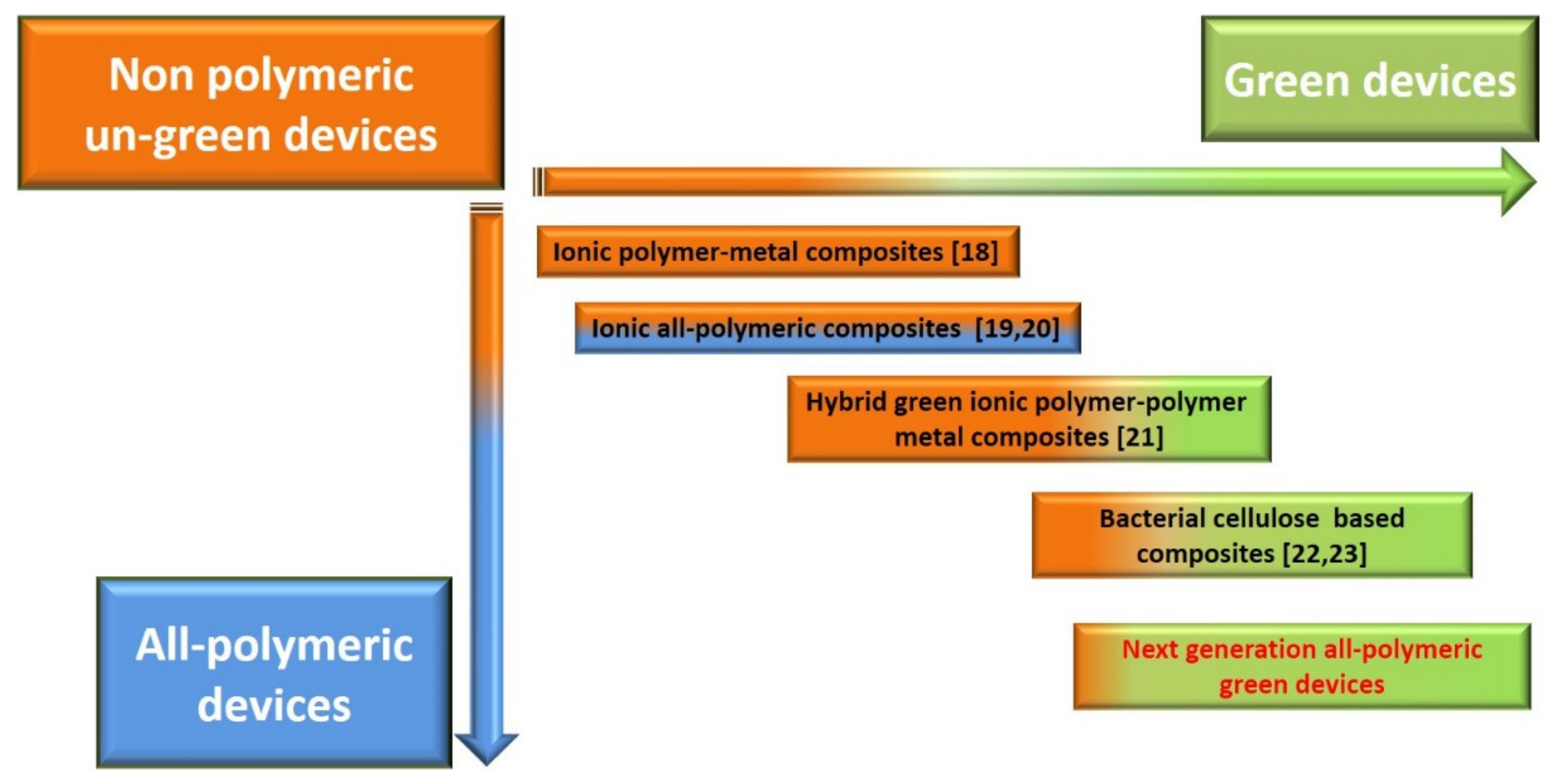
The cost of the sensing system is a relevant constraint that can determine the success of technologies, and the examples reported above are affected by the need for a power source. Such a drawback can be overcome if self-generating materials [10], such as piezoelectric and aluminum nitride (AlN) [11,12,13], are considered. Though sensors based on AlN have raised scientific and industrial interest, micromachined AlN-based devices are based on silicon-based processes [14]. As such, the production of sensors based on this technology cannot be considered green. Moreover, they need dedicated recycling or disposing processes [15,16]. As a final remark, silicon-based devices are rigid, while flexibility is requested from next-generation applications [17]. The need for greener sensing devices, i.e., requiring fewer raw materials and less energy and limited amounts of non-renewable matter and producing more easily disposable, recyclable, or even biodegradable devices, imposes the development of new technologies based on more sustainable and greener materials. A trend is occurring in the field of polymeric materials for sensing applications as suitable candidates for realizing next-generation sensing systems. Such an evolution will require developing new composites in order to improve their performance and produce greener devices. A scheme of the evolution that is occurring in the field of polymeric composites is reported in Figure 1. More specifically, the figure shows a possible evolution from nonpolymeric and un-green devices to polymeric greener ones [18,19,20,21,22,23]. It is worth saying that being polymeric is not a guarantee of greener devices. This is why two directions of possible evolutions are shown in the figure (numbers reported in square brackets indicate papers reported in the References section). The box at the bottom right corner in the figure refers to the final result of the indicated path, i.e., all-polymeric and green sensing devices.
Cellulose is among the most promising base materials for the realization of next-generation flexible and sensing systems, and many applications have been proposed so far [24,25]. More recently, bacterial cellulose (BC), also known as microbial cellulose or bio-cellulose, has been proposed as a greener alternative to plant-derived cellulose [26,27]. It is produced by suitable aerobic bacteria when grown in specific environmental conditions.
Although BC has already been proposed in many applications, including electronics [28], sensors [29], and actuators [30], few examples exist on generating sensors based on BC [31]. In this paper, a flexible generating accelerometer, which exploits BC as the base material, is studied, modelled, and characterized. The device consists of a three-layer structure, obtained by impregnating a BC layer with ionic liquids (ILs). The BC layer is further covered with conducting polymers (CPs) [31,32,33]. The accelerometer is fabricated, therefore, by using greener base products and an environmentally friendly production process.
In [34], a bio-polymer-based accelerometer working in a cantilever configuration has been proposed. That accelerometer uses plant-derived cellulose. Moreover, it requires using zinc oxide nanowires, with a correspondingly more complex and less green fabrication procedure.
The authors have already demonstrated the mechanoelectrical transduction properties of BC impregnated by ILs and covered with CPs [31]. More specifically, it has been shown that this class of composites, when mounted in a cantilever configuration, produces an open circuit voltage signal across the polymeric electrodes because of an applied deformation. In [23], the authors introduced an accelerometer based on BC-IL composites. In this paper, new results are reported. More specifically, the modeling of the BC-based accelerometer and its characterization are proposed. Moreover, an analysis of the transduction principle has been pursued here by experimental investigations, designed by measure to outline specific aspects of the mechano-electric conversion capability of the BC-based transducer.
2. Materials and Methods
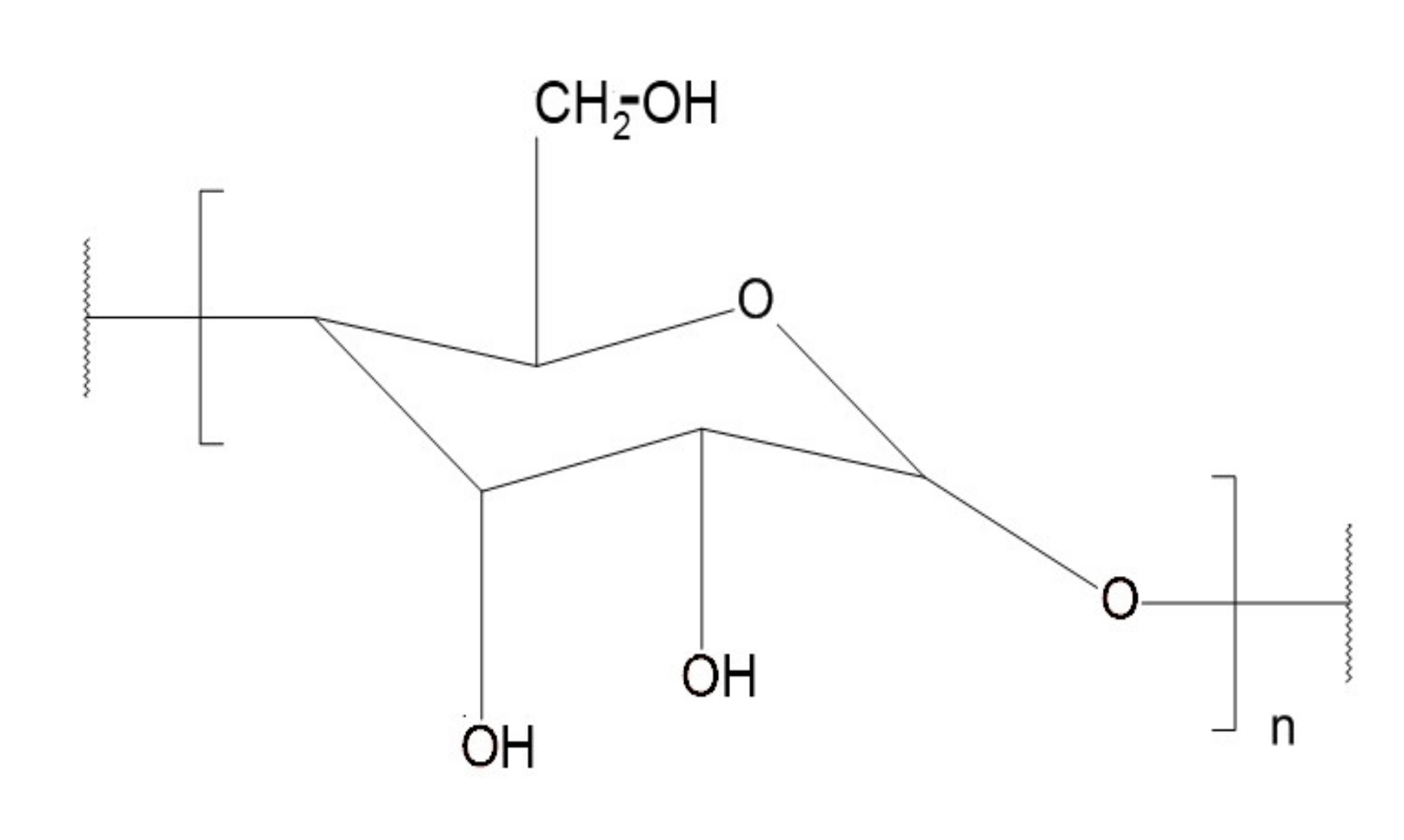
Figure 2 shows the structure of cellulose. Biocompatibility, mechanical, and electrical properties of cellulose have caused a relevant interest for applications, such as medicine and aerial vehicles [35,36,37]. Unfortunately, cellulose is commonly obtained from vegetal stocks with industrial production processes. These require relevant quantities of energy and freshwater. Potentially pollutant wastes are eventually produced.
BC has been proposed as an interesting substitute for plant-derived cellulose [26]. BC is produced by bacteria of the genera Acetobacter, Sarcina ventriculi, and Agrobacterium in suitable solution cultures, where they grow at the interface between the open air and the liquid phase, in a kind of bio industry. Although the BC is characterized by the same chemical structure as plant-derived cellulose, it can be obtained with a higher level of purity. Moreover, BC can be obtained through a greener production process [38].
2.1. Materials
The following materials have been used for the fabrication of the BC-IL-based sensors:
- CBP-GS010 films of BC, purchased from BioFaber (Mesagne, Italy), approximately A4 size.
- 1-Ethyl-3-Methylimidazolium tetrafluoro borate, EMIM-BF4, purchased from Alfa Aesar.
- Poly-(3,4-ethylene-dioxythiophene)-polystyrene-sulfonic acid, PEDOT-PSS, purchased from H.C. Starck (1.3 wt% dispersion in water, Baytron P AG).
The BC was used as the bulk, and EMIM-BF4 was used as the IL to impregnate the BC. The impregnated BC was finally covered on the opposite faces with two films of PEDOT-PSS as electrodes.
2.2. Sample Preparation
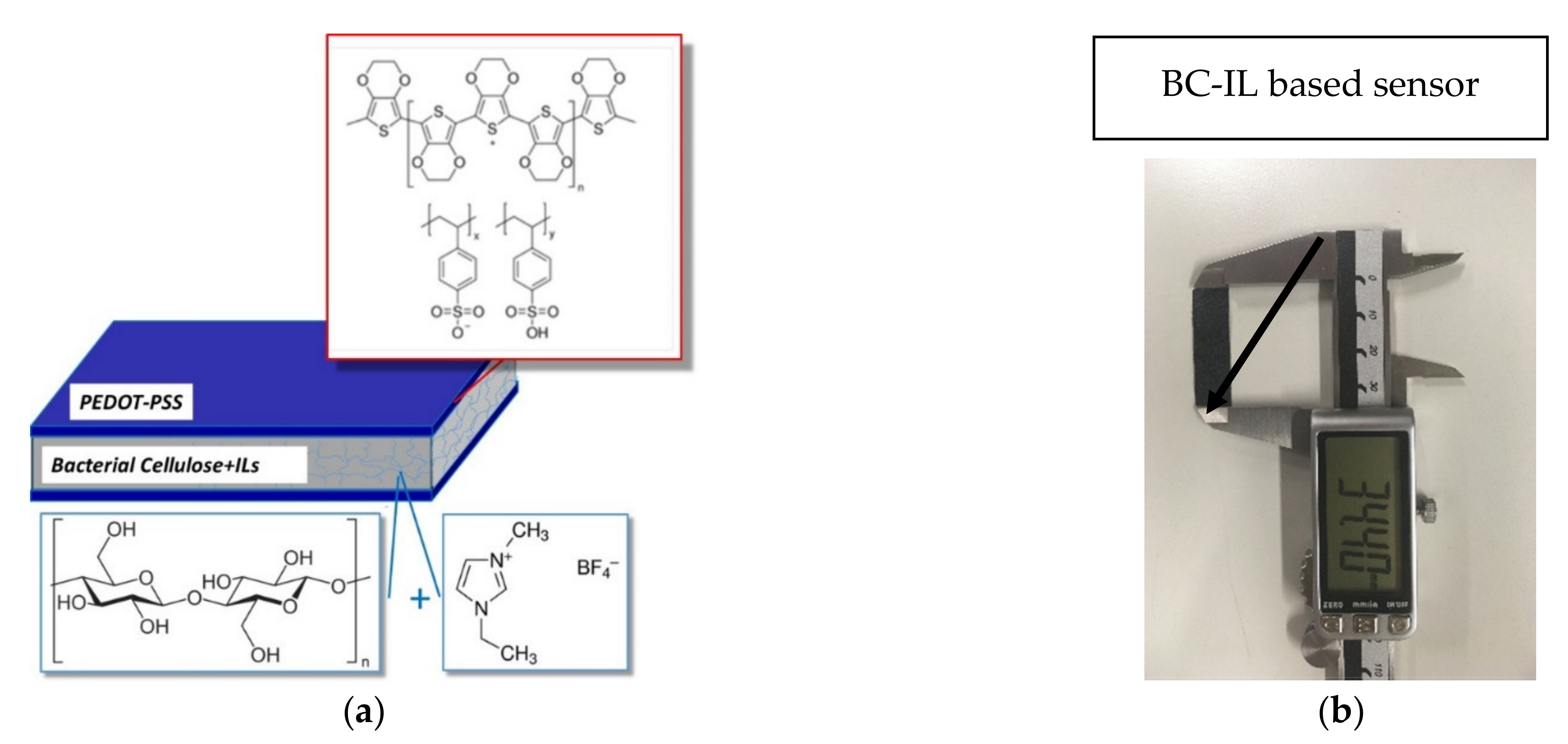
The preparation of the composite used for the sensor has been carried out as follows. Strips of BC (5 cm × 5 cm) were placed for 2 h in an oven at a temperature of 80 °C. After this treatment, a loss of adsorbed water of 4% by weight was observed. The dried strips were then soaked for 24 h with EMIM-BF4 and then placed in an oven at 65 °C for 24 h. Water dispersed PEDOT-PSS was deposited by a film spreader (24 µm) to realize CP electrodes on both sides of the strips. This operation was repeated four times for each side, and after each deposition, the sample was placed for 5 min in an oven at 65 °C. A schematic of the obtained three-layer device is reported in Figure 3a, while a photo of a sample is reported in Figure 3b. For sake of comparison, BC/PEDOT samples were also produced by depositing PEDOT-PSS by the film spreader directly on the opposite faces of the dried BC.
2.3. Characterization Methods
The thermogravimetric measurements, obtained through a Shimadzu DTG-60 instrument, were performed by heating the samples, weighing between 8 and 11 mg, from 35 to 700 °C at a rate of 10 °C min−1. Scanning electron microscopy (SEM) images have been recorded on a Cambridge 90 instrument, equipped with an energy dispersive X-ray microanalysis (EDX) facility. ATR Fourier transform IR (FTIR) spectra were recorded directly on samples, without any preliminary treatment, at a resolution of 2.0 cm−1 in the range 4000 to 650 cm−1 by a PerkinElmer Spectrum 100 spectrometer. The temperature dependence of storage modulus (E′), loss modulus (E″), and tan delta (tan δ = E″/E′) has been evaluated, in tension mode, by using a 2000 TA DMA (Triton Technology Ltd.) and applying a sinusoidal force to a rectangular sample, in the range 25–200 °C, at a working frequency of 1 Hz and a 2 °C/min rate.
3. Modeling
The transducer is modeled as a mass-spring-damping system for the mechanical part of the device, coupled with an electrical model to implement the composite transduction. Hence, the dynamic behavior is defined by a linear second-order differential equation as follows:
where m, x, , d, k, and F(t) correspond to the proof mass located at the free end of the BC in beam configuration; the displacement, velocity, and acceleration of the proof mass; the mechanical damping; the elastic constant; and the kinetic excitation of the transducer, i.e., the mass m, multiplied by the applied acceleration (the measurand). The output voltage is represented by the term V. G is a multiplicative coefficient that models the conversion of the displacement into an output voltage across the two electrodes of the composite. Note that, according to the working conditions investigated in the following, Equation (1) refers to the system working in the proximity of its resonant frequency.
The model has been implemented by using MATLAB Simulink according to the parameter values given in Table 1.
The value of m of the proof mass has been directly measured by a scale (see Section 4), d has been estimated through experiment, and the term k has been estimated by using the equivalent section method [7] as follows:
Emax is the Young’s modulus of the BC; In is the inertial moment normalized, which is the result of the equivalent section method; and l is the length of the beam.
To validate the proposed model, an impulse response of the device has been simulated and compared with the experiments. The experimental validation of the proposed model will be reported in the following section.
4. Results and Discussion
4.1. Composite Composition
The IL uptake was calculated by comparing the weight of the IL-treated sample with the dried ones. The samples were prepared by the same procedure as described before. The following equation was used to evaluate the IL uptake (found to be equal to 34% by weight):
To evaluate the influence of the spreading treatment on the amount of IL remaining in the BC film, the following experiment was carried out. An IL-soaked BC film was treated by a four-time passage of the dry spreader. After this treatment the amount of IL remaining in the BC film was 11% by weight with respect to the starting dried sample. From this information and through the weighing of the sample on which the PEDOT had been deposited, the amount of PEDOT present in the final device was roughly 7% by weight. Considering that both IL and PEDOT can be extracted from the device by a water treatment, we can affirm that about 82% by weight (corresponding to the BC weight fraction) of the materials can be recycled, thus justifying the environmentally friendly nature of our device.
4.2. Structural, Thermal, and Mechanical Characterization
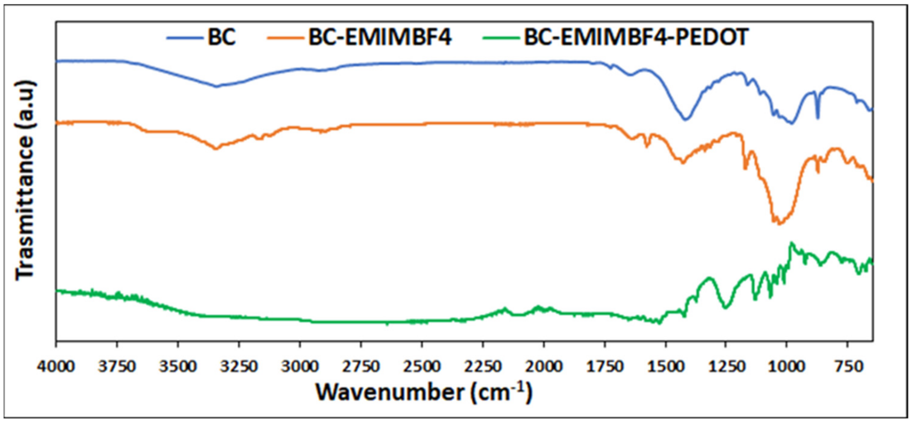
The membrane characterization was carried out by TGA, ATR FTIR, SEM, and DMA analyses. The BC and BC/EMIMBF4 FTIR ATR spectra comparison (see Figure 4) shows that both have the 3000–3600 cm−1 broad band (due to the O–H stretching of the hydroxyl group), the 2920–2880 cm−1 band (due to the aliphatic C–H stretching), the 1640 cm−1 band (bending of absorbed H-O-H), the 1424 cm−1 band (due to in plane bending of H-C-H groups), and the 1110–874 cm−1 bands (deriving from to the stretching of C-OH groups and from the asymmetric stretching of the C-O-C bonds).
The IL absorption produces some disruption of the cellulose crystalline domains as suggested by the significant decrease in the intensity of two bands characteristic of the presence of cellulose crystalline structures (the one centered at 1424 cm−1 and the one centered at 874 cm−1) [39]. The ATR-FTIR spectrum of the BC/EMIMBF4/PEDOT membrane (Figure 4) shows characteristic peaks of both cellulose and PEDOT. The signals due to cellulose are the ones centered at 1645 cm−1, 1421 cm−1, and 1041 cm−1, while the ones due to the PEDOT electrode are centered at 1576 cm−1 (C=C), 1254 cm−1 (C-C), and 948 cm−1 (S-O), characteristic of the thiophene ring.
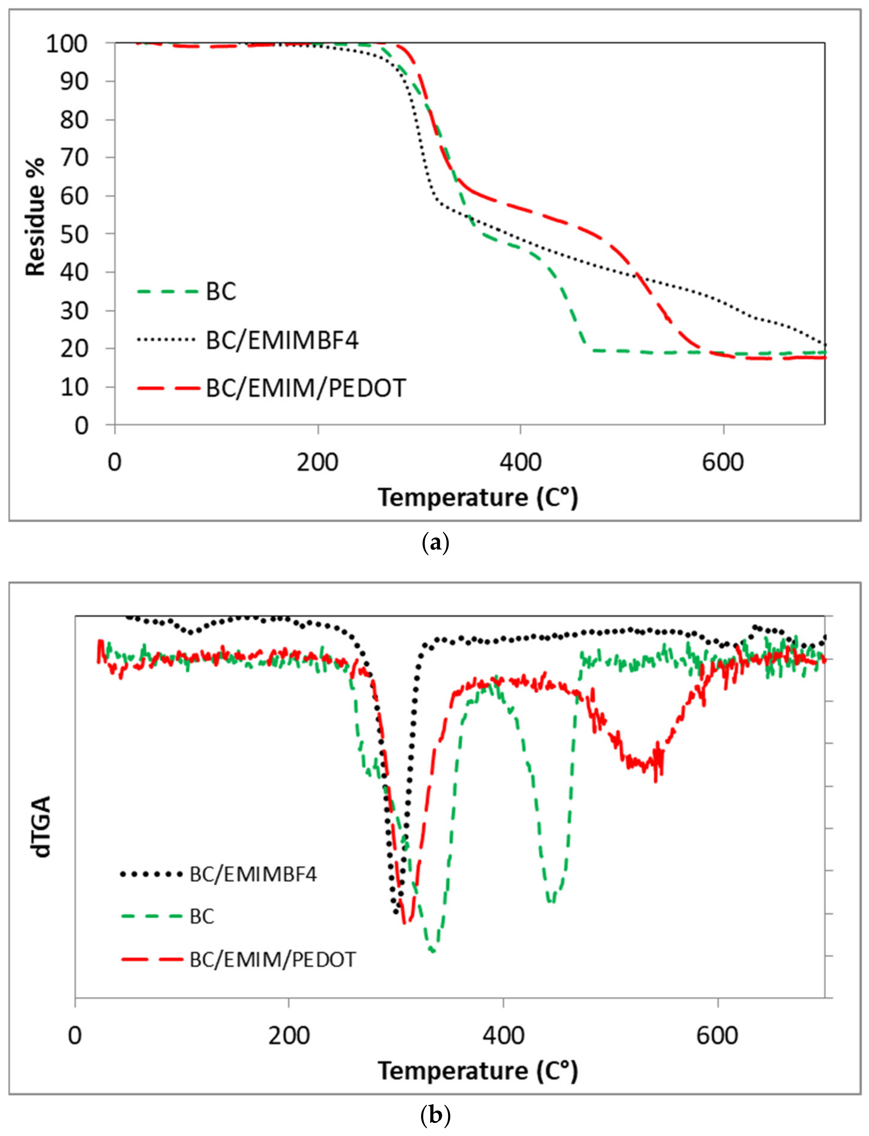
As a confirmation of the decrease of BC crystallinity, TGA showed that the presence of EMIM-BF4 promotes cellulose degradation (see Figure 5a,b). The maximum weight loss rate occurred at 336 °C for BC, while the BC/EMIM BF4 sample showed a marked decrease of such a temperature (302 °C). In the case of BC/EMIMBF4/PEDOT, the maximum weight loss rate occurred at 312 °C, presumably because the PEDOT-PSS layer offers an obstacle to degradation product loss, as confirmed by the shift toward higher temperatures of the last maximum weight loss rate centered at 446 °C in the case of BC and at about 531 °C for the BC/EMIMBF4/PEDOT sample.
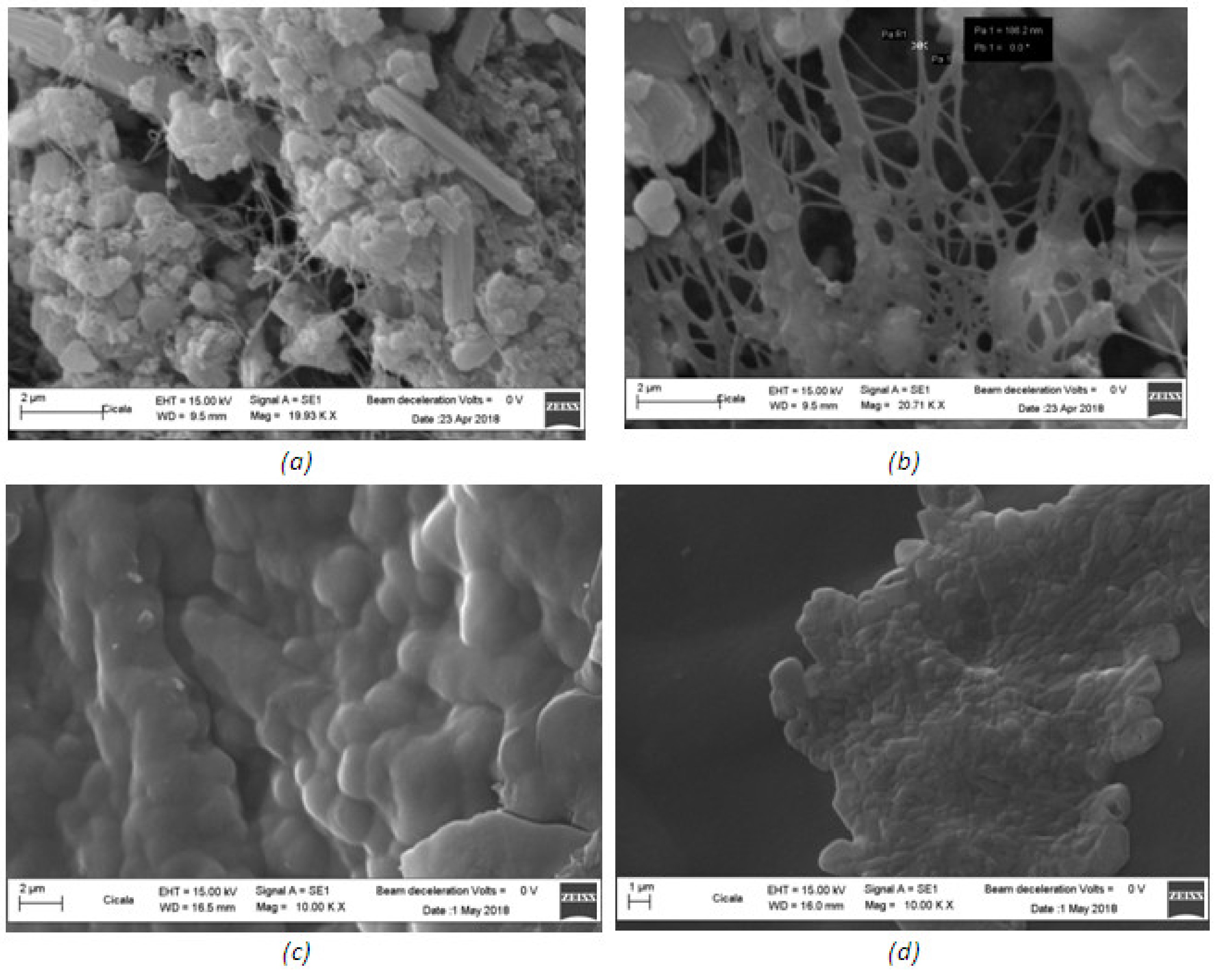
The SEM micrograph of BC (Figure 6a) showed a cellulose morphology consisting of regions rich in spherical agglomerates between which filamentous and rod-like structures can be seen. The sample BC/EMIMBF4 SEM images showed that after the IL treatment, only a few almost spherical agglomerates survive. These features probably suggest that BC interaction with IL produces swelling/degradation of the crystalline domain (Figure 6b), resulting in a fiber-like feature predominance. SEM images of BC/PEDOT sample showed that PEDOT deposition on the surface of BC determines the filling of the empty spaces among BC agglomerates, producing a regular surface where the shape of the underlying agglomerations can still be detected (Figure 6c). The SEM micrograph of the whole composite (BC/EMIM/PEDOT) showed that on the smooth and homogeneous conducting layer surface, it was possible to observe island features (Figure 6d), presumably rich in IL, as revealed by EDX.
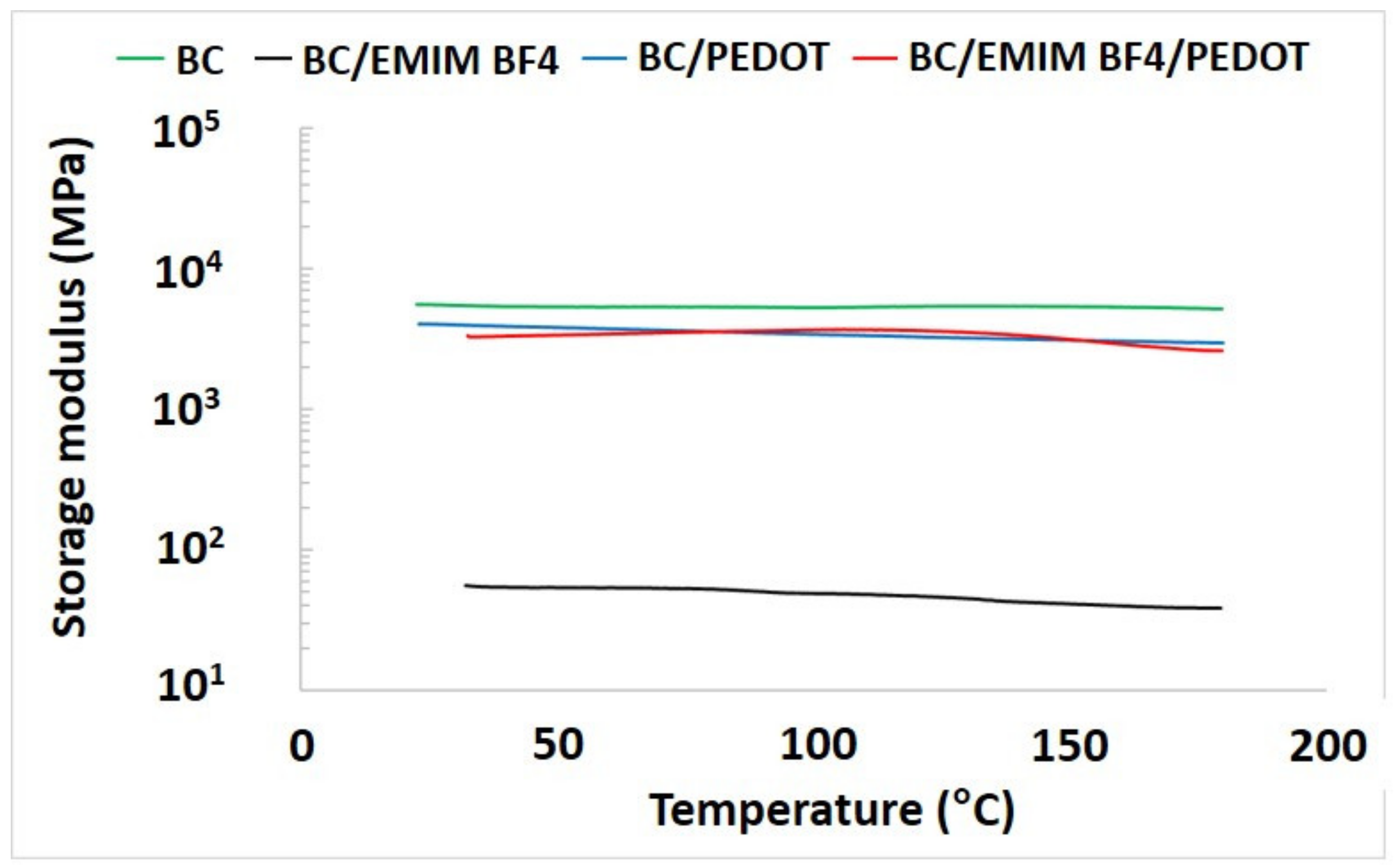
The results of the DMA investigation carried out on BC, BC/EMIM BF4, BC/PEDOT, and BC/EMIM BF4/PEDOT samples are shown in Figure 7. The investigation was performed as a function of the working temperature.
The storage modulus of BC shows a negligible decrease (from 5.5 × 10³ MPa at 30 °C to 5.3 × 10³ MPa at 170 °C) as the temperature increases. In this range of temperature, some modulus enhancement is recorded around 100 °C, where because of water loss and consequent increasing of the packing density, the modulus increases from 5.30 × 10³ MPa to 5.45 × 10³ MPa. The lower density of BC crystalline domains produced by the soaking of BC with EMIM BF4 determines a dramatic decrease of storage modulus compared to the BC one (from 5.5 × 10³ MPa to 54 MPa at 30 °C, respectively). The presence of the PEDOT layer does not significantly modify the storage modulus of BC (i.e., 5.5 × 10³ MPa for BC vs. 4 × 10³ MPa at 30 °C for BC/PEDOT sample), but the lower amount of IL present in the sample after the PEDOT spreading determines a dramatic increase in the storage modulus of BC/EMIMBF4/PEDOT (i.e., 54 MPa at 30 °C for BC/EMIMBF4 sample vs. 3.3 × 10³ MPa of the BC/EMIMBF4/PEDOT sample).
4.3. Mechanoelectrical Transduction
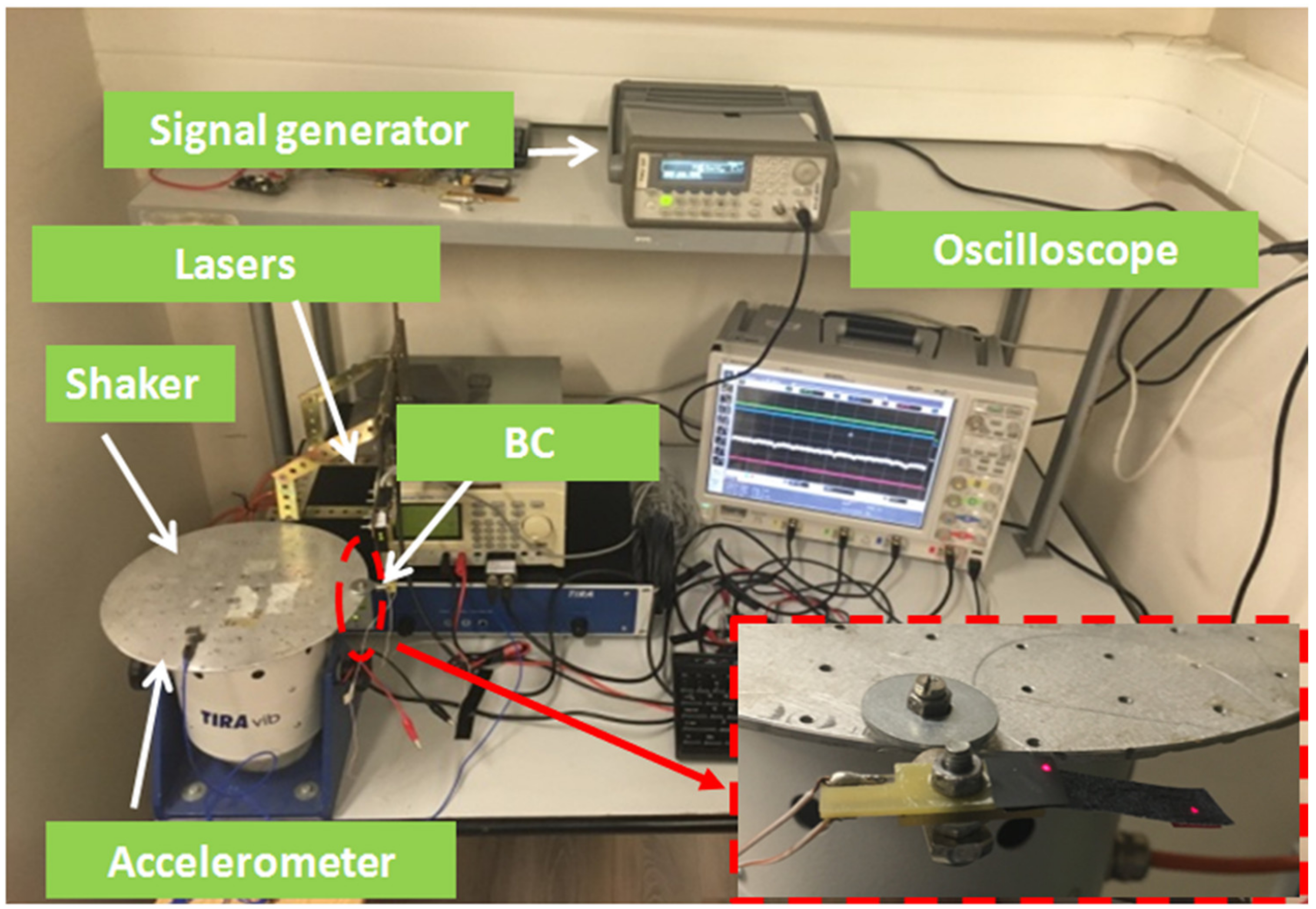
The mechanoelectrical transduction properties of BC-IL-based devices were investigated by an experimental setup, realized by measure. The setup used to characterize the inertial motion sensor as an accelerometer is seen in Figure 8. It consists of:
- A TIRA GmbH S503 shaker to impose a base motion of the sensor mounted in the cantilever configuration;
- A Keysight 33220A signal generator, required for driving the shaker;
- A digital oscilloscope (Agilent Infiniium MSO9064A), which is used both for a visual inspection of the relevant signals and their acquisition;
- Two Baumer 12U6460/S35A laser sensors. These are used to measure the displacements at the anchor and at the sensor tip, respectively;
- An accelerometer (model PCB333B40-SN51174) is mounted to the shaker moving plate and works as the reference.
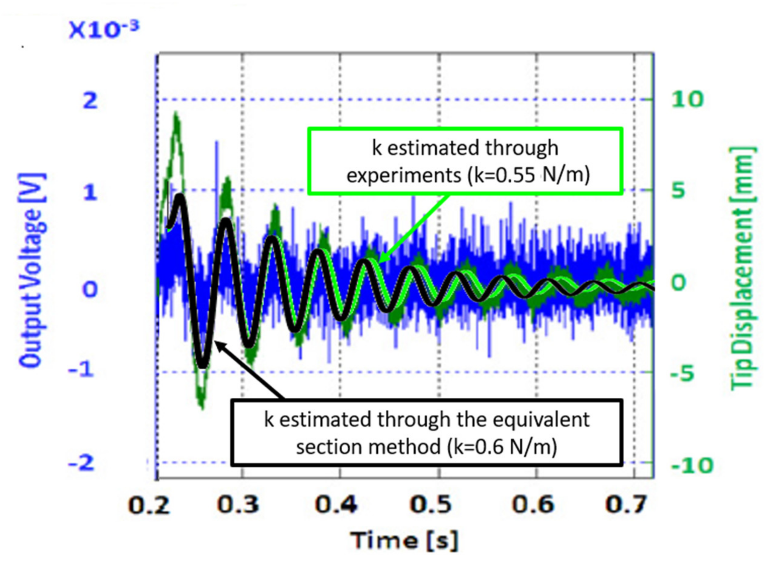
A preliminary investigation in terms of impulse response has been accomplished, and a comparison to the estimation obtained by the model presented in Section 3 has been done. Figure 9 shows the tip displacement and the output voltage of the BC composite, considering the parameters defined in Table 1. The values of the elastic constant estimated, as obtained by Equation (2) and by experiments, have been compared. A difference between the values of the model and experiments of about 8% has been estimated.
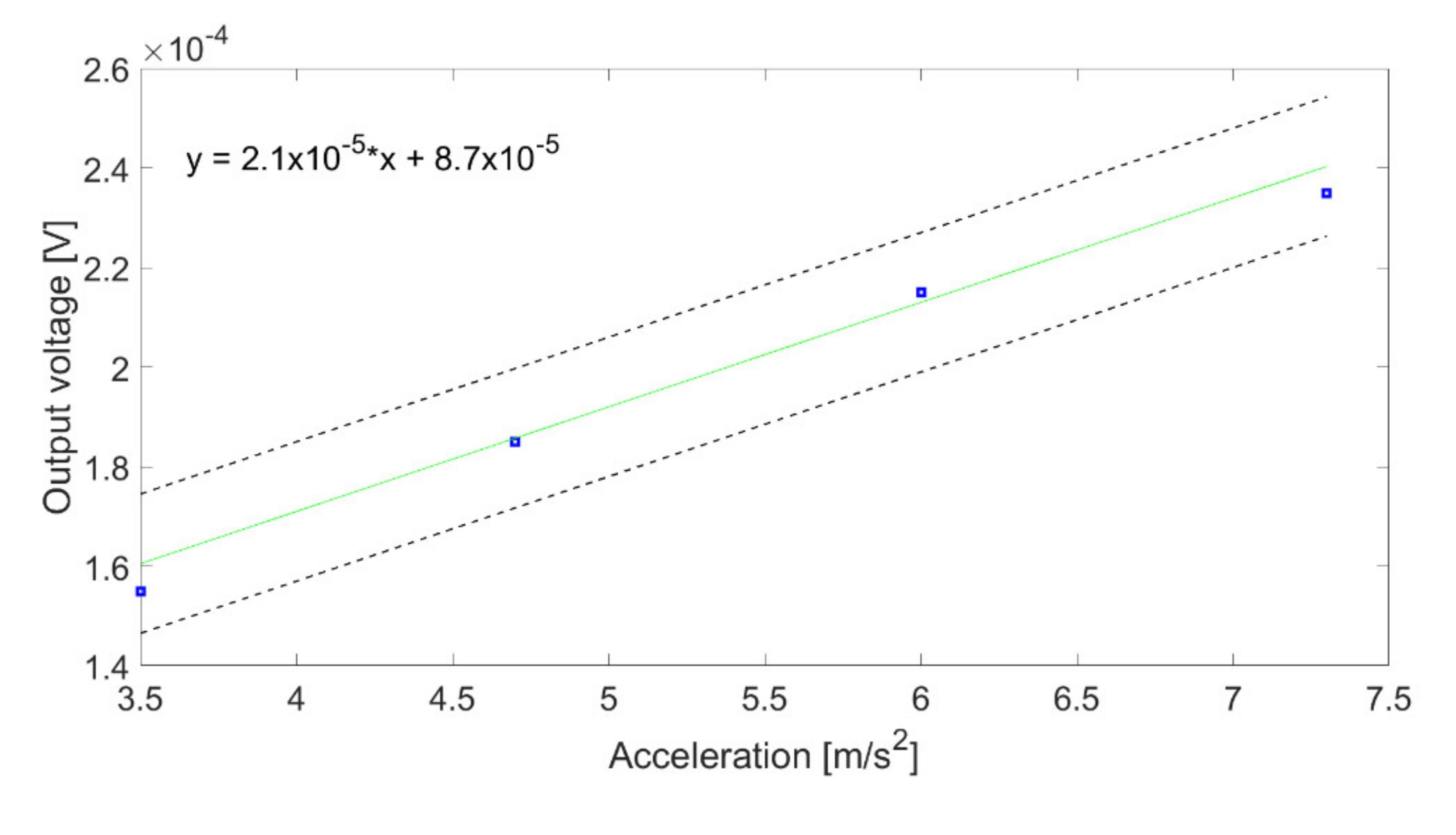
Furthermore, an investigation was performed for determining the resonant frequency of the sensor [23]. Then, sinusoidal signals at the resonant frequency of the system were applied at the sensor’s fixed end by using the shaker. The amplitude of the applied signal was used to control the acceleration applied to the device. Figure 10 shows the results of the sensor characterization. The figure reports the estimated mean values and the corresponding uncertainty, considering acceleration values ranging in the interval 3 m/s2 to 7.5 m/s2. The least mean-square algorithm was used to regress data and estimate the corresponding linear characteristic curve. This is reported with a solid line in Figure 10. The two dashed lines represent the uncertainty band. A sensitivity of 2.1 × 10⁻⁵ V/m/s2 has been estimated. The noise level resulted in about 0.1 × 10⁻⁴ V, corresponding to a resolution of about 0.47 m/s2.
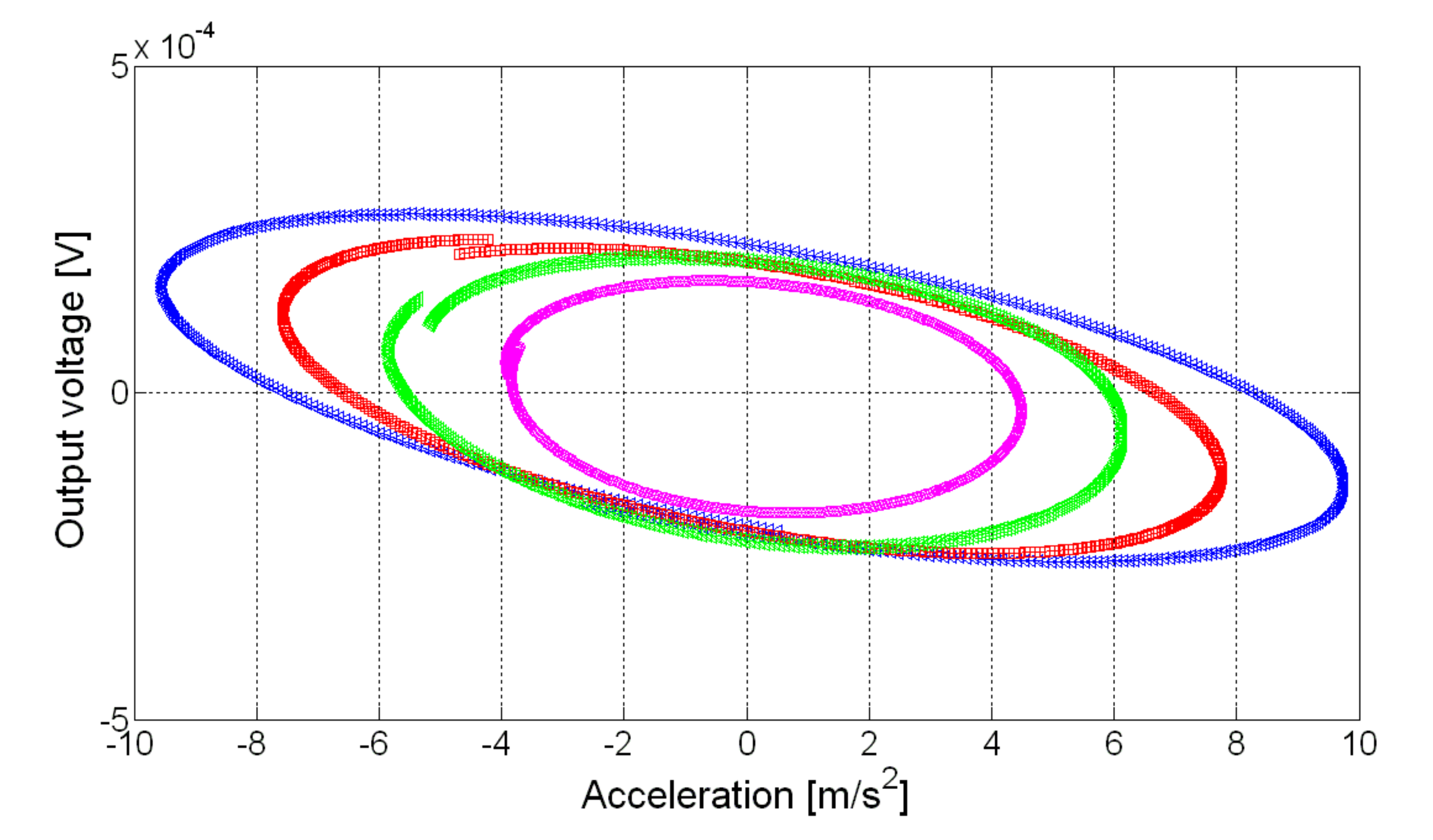
The transduction performance of the compound was further investigated to outline the presence of nonlinearities. The input–output signals at the resonance frequency were considered for this aim. Moreover, to filter out any high-frequency noise effect, a pre-filtering was performed on both signals by using a digital low pass filter for both signals, with a cut-off frequency equal to 35 Hz. Such a value was chosen to maintain the relevant signal while removing the power line contribution. Signals of different amplitude values were imposed on the system. The input–output plots for four values of the acceleration are shown in Figure 11. A perusal of the figure shows that the increase of the input acceleration does not produce a proportional change in the output voltage, which gives evidence of system nonlinearity, so that results reported in Figure 10 can be considered as a form of linearization of the system behavior in the considered range. The presence of low-frequency fluctuations in the output signal (an example of the input–output curve for some nominally identical periods is given in Figure 12) did not allow for a deeper investigation of the system nonlinearity.
4.4. The Investigation on the Mechanoelectrical Transduction Nature
This section explores the mechanoelectrical transduction nature of the BC-based composite. BC-based compounds, impregnated with ILs and covered with conducting layers, have been reported to have electromechanical transduction capabilities because of piezoionic properties, i.e., because of the migration of charged species. According to such properties, the BC-based composite investigated in this paper should be classified as an ionic-electroactive polymer (IEAP).
- IEAPs are characterized by both electromechanical and mechanoelectrical transduction properties.
- An inversion of polarity between the mechanical signal and the electrical one is observed when the two transduction phenomena are investigated.
- The sign of the charges accumulated at each electrode depends on the nature of the prevailing mobile charges.
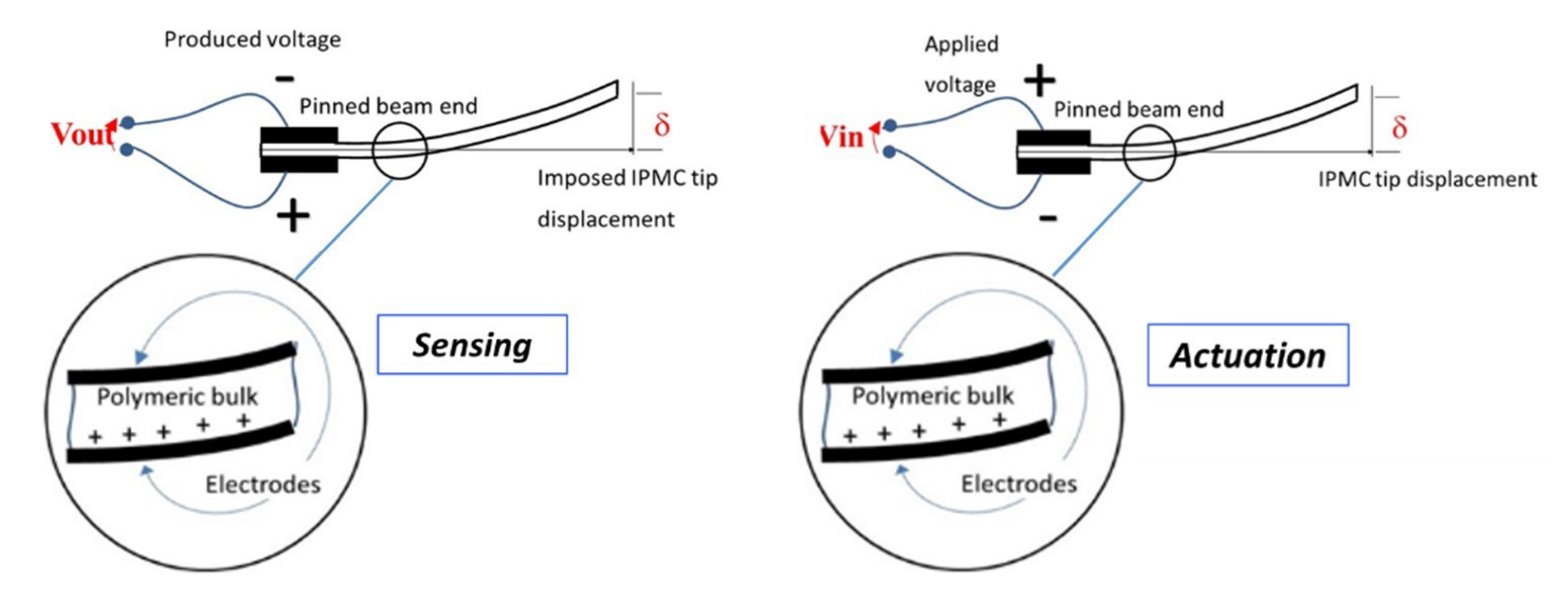
In a previous work [40], some of the authors gave indirect experimental evidence of the piezoionic nature of the involved transduction phenomenon. However, in that contribution, no investigation was performed on the nature of the mobile charges. Here, experimental evidence will be given compatible with the hypothesis that mobile charges are cations. Suppose that we are in the presence of mobile cations; the schemes in Figure 13 show the cations’ redistribution. Up-deflections and positive charges at the top electrodes are assumed as positive.
As it can be noted, the same tip deflection implies a voltage signal of opposite polarities for the sensing and actuating working modes. Moreover, when the tip of the sensor is deflected in the up direction, positive charges accumulate at the bottom face.
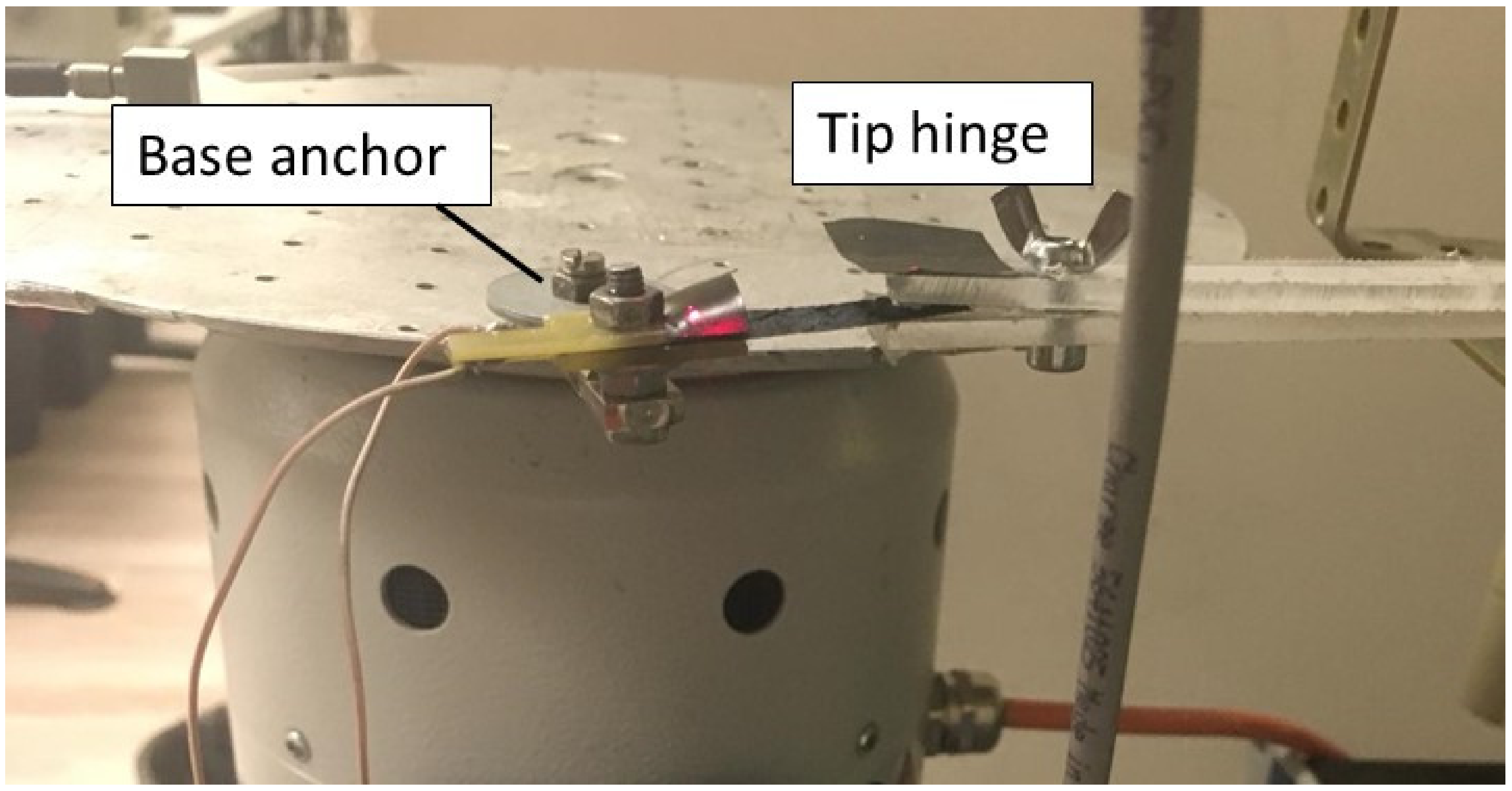
Experiments on the BC-based compound, both as a sensor and as an actuator, have been performed by modifying the experimental setup shown in Figure 8 (see Figure 14). More specifically, low-frequency signals were applied by using the modified setup, which includes a fork-shaped hinge for forcing the composite tip motion.
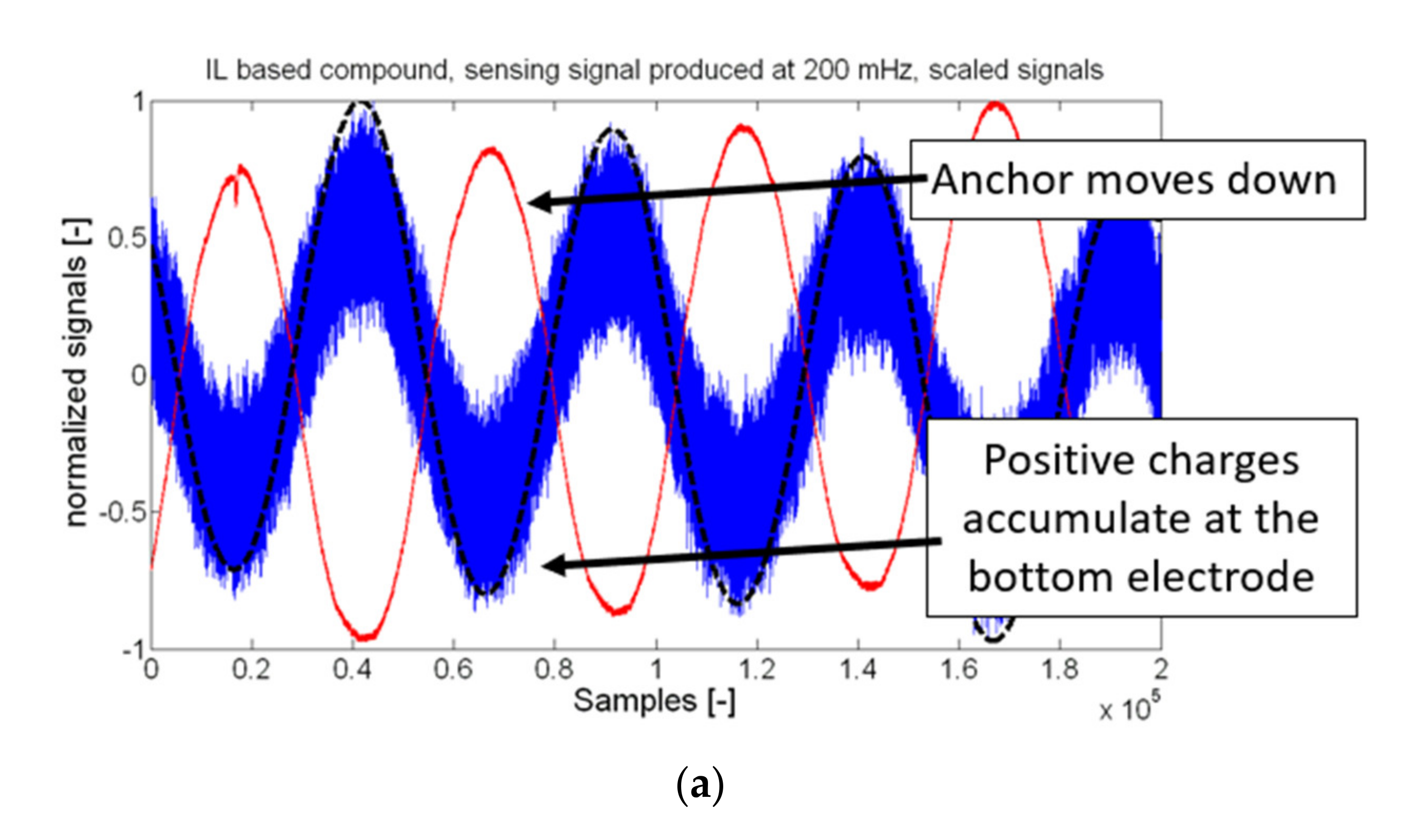
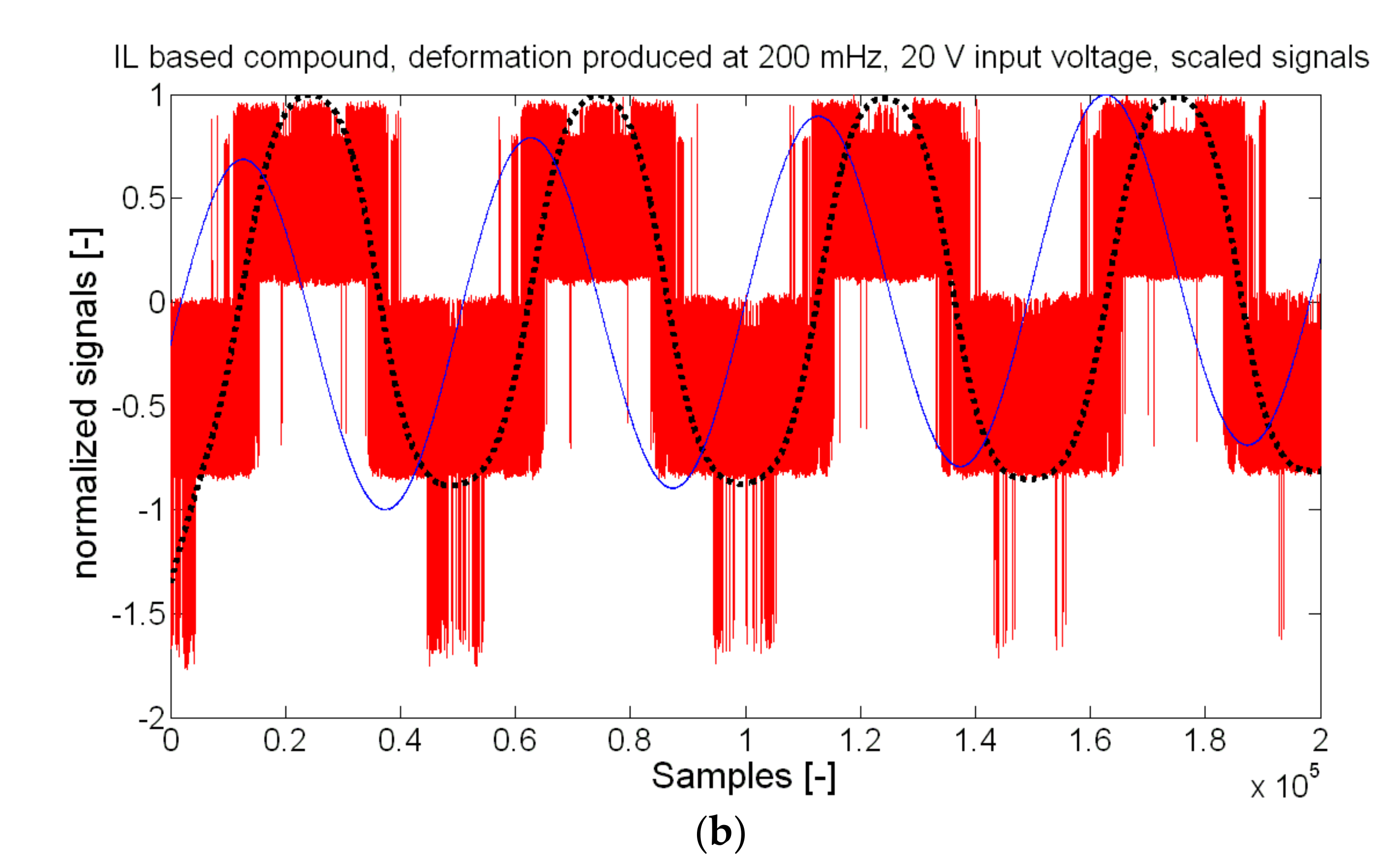
A comparison of the signals obtained when sensing and as actuating working modes (polarities are as indicated in the schematic) is shown in Figure 15a,b, respectively.
Results evince that there is a change in phase between the sensing and acting signals. Moreover, a motion of the anchor in the down direction produced an accumulation of positive charges at the bottom electrode. Such results are compatible with the hypothesis that the redistribution of positive charges is involved in the transduction phenomenon.
Finally, while sensing signals are in phase opposition, a small phase lag was observed for the actuation signals. The existence of such a phase lag for the case of the actuation needs further investigation.
5. Conclusions
In this paper, we experimentally investigated and modelled a more environmentally friendly accelerometer. The sensor was fabricated by using BC as the substrate. BC was then impregnated by an ionic liquid (1-Ethyl-3-Methylimidazolium tetrafluoro borate, EMIM BF4) and finally covered, on the opposite faces, with a conducting polymer (Poly-(3,4-ethylene-dioxythiophene)-polystyrene-sulfonic acid, PEDOT-PSS) to form the sensor electrodes. The proposed system was mounted in a cantilever configuration and worked as a generating sensor. A voltage signal was produced when mechanically excited.
In the paper, the structural, thermal, mechanical, and mechanoelectrical characterizations of the devices as accelerometers are reported. After a linear regression was performed on the experimental data, a sensitivity of ~2.1 × 10⁻⁵ V/m/s2 was obtained. The noise level resulted in being about 0.1 × 10⁻⁴ V, corresponding to a resolution of the BC-based accelerometer of ~0.47 m/s2. A data-driven model was proposed for the observed transduction.
Compared with competing technologies, including MEMS devices, the proposed system uses a biopolymer-based substrate and organic conductors, which have been reported to be biocompatible. Issues exist in the final environmental impact of ILs. Nevertheless, new bio-derived ILs could be used for realizing accelerometers, decreasing the environmental impact of the proposed BC-based inertial sensor.
Author Contributions
Conceptualization, C.T. and S.G.; methodology, C.T., S.G., and A.P.; validation, C.T., S.G., S.C., G.D.P., and A.P.; formal analysis, C.T. and S.G.; investigation, C.T., S.G., G.D.P., and A.P.; data curation, C.T., S.G., G.D.P., and A.P.; writing—original draft preparation, C.T. and S.G. All authors have read and agreed to the published version of the manuscript.
Funding
The research activity was partially funded by PIAno di inCEntivi per la RIcerca di Ateneo (PIACERI), Linea 2—SENSori polimerici INtelligenti per l’implementazione di una società Green (SENSING), University of Catania.
Conflicts of Interest
The authors declare no conflict of interest.
References
- Carminati, M.; Ferrari, G.; Sampietro, M. Emerging miniaturized technologies for airborne particulate matter pervasive monitoring. Measurement 2017, 101, 250–256. [Google Scholar] [CrossRef]
- Naifar, S.; Trigona, C.; Bradai, S.; Baglio, S.; Kanoun, O. Characterization of a Smart Transducer for Axial Force Measurements in Vibrating Environments. Measurement. Measurement 2020, 16, 108157. [Google Scholar] [CrossRef]
- Benser, E.T. Trends in inertial sensors and applications. IEEE Int. Symp. Inert. Sens. Syst. (ISISS) 2015, 2015, 1–4. [Google Scholar]
- Lawrence, A.A. Modern Inertial Technology: Navigation, Guidance, and Control; Springer Science & Business Media: Berlin, Germany, 2012. [Google Scholar]
- Chaehoi, A.; Mailly, F.; Latorre, L.; Nouet, P. Experimental and finite-element study of convective accelerometer on CMOS. Sens. Actuators A Phys. 2006, 132, 78–84. [Google Scholar] [CrossRef] [Green Version]
- Trigona, C.; Ando, B.; Baglio, S. Design, fabrication, and characterization of BESOI-accelerometer exploiting photonic bandgap materials. IEEE Trans. Instrum. Meas. 2014, 63, 702–710. [Google Scholar] [CrossRef]
- Andò, B.; Baglio, S.; L’Episcopo, G.; Marletta, V.; Savalli, N.; Trigona, C. A BE-SOI MEMS for inertial measurement in geophysical applications. IEEE Trans. Instrum. Meas. 2011, 60, 1901–1908. [Google Scholar] [CrossRef]
- Nihtianov, S.; Luque, A. Smart Sensors and MEMS: Intelligent Sensing Devices and Microsystems for Industrial Applications, eds. Smart Sensors and MEMS: Intelligent Sensing Devices and Microsystems for Industrial Applications; Woodhead Publishing: Sawston, UK, 2018. [Google Scholar]
- Aydemir, A.; Terzioglu, Y.; Akin, T. A new design and a fabrication approach to realize a high performance three axes capacitive MEMS accelerometer. Sens. Actuators A Phys. 2016, 244, 324–333. [Google Scholar] [CrossRef]
- Giusa, F.; Maiorca, F.; Noto, A.; Trigona, C.; Andò, B.; Baglio, S. A diode-less mechanical voltage multiplier: A novel transducer for vibration energy harvesting. Sens. Actuators A Physical 2014, 212, 34–41. [Google Scholar] [CrossRef]
- Shen, Z.; Tan, C.Y.; Yao, K.; Zhang, L.; Chen, Y.F. A miniaturized wireless accelerometer with micromachined piezoelectric sensing element. Sens. Actuators A Phys. 2016, 241, 113–119. [Google Scholar] [CrossRef]
- Saranya, B.T.; Anjana, C.; Tina, B.S.; Seena, V. Polymer piezoresistive MEMS accelerometer with integrated ITO. In Proceedings of the 2017 IEEE 12th Nanotechnology Materials and Devices Conference (NMDC), Singapore, 2–4 October 2017; pp. 127–128. [Google Scholar]
- Wang, Y.; Ding, H.; Le, X.; Wang, W.; Xie, J. A MEMS piezoelectric in-plane resonant accelerometer based on aluminum nitride with two-stage microleverage mechanism. Sens. Actuators A Phys. 2017, 254, 126–133. [Google Scholar] [CrossRef]
- Bernstein, J. An overview of MEMS inertial sensing technology. Sens.-J. Appl. Sens. Technol. 2003, 20, 14–21. [Google Scholar]
- Baldé, C.P.; Forti, V.; Gray, V.; Kuehr, R.; Stegmann, P. The global e-Waste Monitor 2017: Quantities, Flows and Resources; United Nations University, International Telecommunication Union, and International Solid Waste Association: Tokyo, Japan, 2017. [Google Scholar]
- UN Report: Time to Seize Opportunity, Tackle Challenge of e-Waste. Available online: https://www.unenvironment.org/news-and-stories/press-release/un-report-time-seize-opportunity-tackle-challenge-e-waste (accessed on 22 August 2021).
- Roselli, L.; Mariotti, C.; Mezzanotte, P.; Alimenti, F.; Orecchini, G.; Virili, M.; Carvalho, N.B. Review of the present technologies concurrently contributing to the implementation of the Internet of Things (IoT) paradigm: RFID, Green Electronics, WPT and Energy Harvesting. Conference on Wireless Sensors and Sensor Networks (WiSNet). In Proceedings of the 2015 IEEE Topical Conference on Biomedical Wireless Technologies, Networks, and Sensing Systems (BioWireleSS), San Diego, CA, USA, 26–30 May 2015; pp. 1–3. [Google Scholar]
- Shahinpoor, M. Ionic Polymer Metal Composites (IPMCs)—Smart Multi-Functional Materials and Artificial Muscles; Royal Society of Chemistry: Cambridge, UK, 2016. [Google Scholar]
- Di Pasquale, G.; Fortuna, L.; Graziani, S.; La Rosa, M.; Nicolosi, D.; Sicurella, G.; Umana, E. All-organic motion sensors: Electromechanical modeling. IEEE Trans. Instrum. Meas. 2009, 58, 3731–3738. [Google Scholar] [CrossRef]
- Temmer, R.; Maziz, A.; Plesse, C.; Aabloo, A.; Vidal, F.; Tamm, T. In search of better electroactive polymer actuator materials: PPy versus PEDOT versus PEDOT-PPy composites. Smart Mater. Struct. 2013, 22, 104006. [Google Scholar] [CrossRef]
- Aabloo, A.; De Luca, V.; Di Pasquale, G.; Graziani, S.; Gugliuzzo, C.; Johanson, U.; Marino, C.; Pollicino, A.; Puglisi, R. A new class of ionic electroactive polymers based on green synthesis. Sens. Actuators A Phys. 2016, 249, 32–44. [Google Scholar] [CrossRef]
- Kim, S.S.; Jeon, J.H.; Kee, C.D.; Oh, I.K. Electro-active hybrid actuators based on freeze-dried bacterial cellulose and PEDOT:PSS. Smart Mater. Struct. 2013, 22, 085026. [Google Scholar] [CrossRef]
- Di Pasquale, G.; Graziani, S.; Pollicino, A.; Trigona, C. Green Inertial Sensors based on Bacterial Cellulose. In Proceedings of the 2019 IEEE Sensors Applications Symposium (SAS), Sophia Antipolis, France, 11–13 March 2019; pp. 1–4. [Google Scholar]
- Jung, Y.H.; Chang, T.H.; Zhang, H.; Yao, C.; Zheng, Q.; Yang, V.W.; Jiang, H. High-performance green flexible electronics based on biodegradable cellulose nanofibril paper. Nat. Commun. 2015, 6, 1–11. [Google Scholar] [CrossRef]
- Mahadeva, S.K.; Yun, S.; Kim, J. Flexible humidity and temperature sensor based on cellulose–polypyrrole nanocomposite. Sens. Actuators A Phys. 2011, 165, 194–199. [Google Scholar] [CrossRef]
- Iguchi, M.; Yamanaka, S.; Budhiono, A. Bacterial cellulose—A masterpiece of nature’s arts. J. Mater. Sci. 2000, 35, 261–270. [Google Scholar] [CrossRef]
- Gregory, D.A.; Tripathi, L.; Fricker, A.T.R.; Asare, E.; Orlando, I.; Raghavendran, V.; Roy, I. Bacterial cellulose: A smart biomaterial with diverse applications. Mater. Sci. Eng. R Rep. 2021, 145, 100623. [Google Scholar] [CrossRef]
- Yuen, J.D.; Shriver-Lake, L.C.; Walper, S.A.; Zabetakis, D.; Breger, J.C.; Stenger, D.A. Microbial nanocellulose printed circuit boards for medical sensing. Sensors 2020, 20, 2047. [Google Scholar] [CrossRef] [Green Version]
- Hosseini, H.; Kokabi, M.; Mousavi, S.M. Conductive bacterial cellulose/multiwall carbon nanotubes nanocomposite aerogel as a potentially flexible lightweight strain sensor. Carbohydr Pol. 2018, 201, 228–235. [Google Scholar] [CrossRef]
- Jeon, J.H.; Oh, I.K.; Kee, C.D.; Kim, S.J. Bacterial cellulose actuator with electrically driven bending deformation in hydrated condition. Sens. Actuators B Chem. 2010, 146, 307–313. [Google Scholar] [CrossRef]
- Di Pasquale, G.; Graziani, S.; Pollicino, A.; Trigona, C. Performance Characterization of a Biodegradable Deformation Sensor Based on Bacterial Cellulose. IEEE Trans. Instrum. Meas. 2019, 69, 2561–2569. [Google Scholar] [CrossRef]
- Mangayil, R.; Rajala, S.; Pammo, A.; Sarlin, E.; Luo, J.; Santala, V.; Karp, M.; Tuukkanen, S. Engineering and Characterization of Bacterial Nanocellulose Films as Low Cost and Flexible Sensor Material. ACS Appl. Mater. Interfaces 2017, 9, 19048–19056. [Google Scholar] [CrossRef] [PubMed]
- Esa, F.; Tasirin, S.M.; Rahman, N.A. Overview of bacterial cellulose production and application. Agric. Agric. Sci. Procedia 2014, 2, 113–119. [Google Scholar] [CrossRef] [Green Version]
- Wang, Y.H.; Song, P.; Li, X.; Ru, C.; Ferrari, G.; Balasubramanian, P.; Amabili, M.; Sun, Y.; Liu, X. A paper-based piezoelectric accelerometer. Micromachines 2018, 9, 1–12. [Google Scholar] [CrossRef] [PubMed] [Green Version]
- Kim, J.; Yun, S.; Ounaies, Z. Discovery of cellulose as a smart material. Macromolecules 2006, 39, 4202–4206. [Google Scholar] [CrossRef]
- Mano, J.F.; Silva, G.A.; Azevedo, H.S.; Malafaya, P.B.; Sousa, R.A.; Silva, S.S.; Boesel, L.F.; Oliveira, J.M.; Santos, T.C.; Marques, A.P.; et al. Natural origin biodegradable systems in tissue engineering and regenerative medicine: Present status and some moving trends. J. R. Soc. Interface 2006, 4, 999–1030. [Google Scholar] [CrossRef] [Green Version]
- Grau, G.; Frazier, E.J.; Subramanian, V. Printed unmanned aerial vehicles using paper-based electroactive polymer actuators and organic ion gel transistors. Microsyst. Nanoeng. 2016, 2, 16032. [Google Scholar] [CrossRef] [Green Version]
- Fernandes, I.D.A.A.; Pedro, A.C.; Ribeiro, V.R.; Bortolini, D.G.; Ozaki, M.S.C.; Maciel, G.M.; Haminiuk, C.W.I. Bacterial cellulose: From production optimization to new applications. Int. J. Biol. Macromol. 2020, 164, 2598–2611. [Google Scholar] [CrossRef]
- Spiridon, I.; Teaca, C.A.; Bodîrlău, R. Structural changes evidenced by FTIR spectroscopy in cellulose materials after pre-treatment with ionic liquid and enzymatic hydrolysis. BioResources 2011, 6, 400–413. [Google Scholar] [CrossRef]
- Trigona, C.; Di Pasquale, G.; Graziani, S.; Licciulli, A.; Nisi, R.; Pollicino, A. Geometrical and Thermal Influences on a Bacterial Cellulose-Based Sensing Element. Akta Imeko Spec. Issue MetroInd 2019, 4, 9. [Google Scholar]
Figure 1.
Scheme of the evolution that is occurring in the field of polymeric materials (numbers in brackets indicate papers reported in the References section).
Figure 1.
Scheme of the evolution that is occurring in the field of polymeric materials (numbers in brackets indicate papers reported in the References section).

Figure 2.
BC chemical structure.

Figure 3.
(a) Schematic of the obtained three-layer sensor; (b) a photo of the realized device.

Figure 4.
FTIR ATR spectra of BC, BC-EMIMBF4, and BC-EMIMBF4-PEDOT.

Figure 5.
TGA (a) and dTGA (b) of samples BC, BC/EMIMBF4, and BC/EMIM/PEDOT (© [2021] IEEE. Reprinted, with permission, from [23]).
Figure 5.
TGA (a) and dTGA (b) of samples BC, BC/EMIMBF4, and BC/EMIM/PEDOT (© [2021] IEEE. Reprinted, with permission, from [23]).

Figure 6.
SEM micrographs of (a) BC, (b) BC/EMIMBF4, (c) BC/PEDOT, and (d) BC/EMIM/PEDOT samples (© [2021] IEEE. Reprinted, with permission, from [23]).
Figure 6.
SEM micrographs of (a) BC, (b) BC/EMIMBF4, (c) BC/PEDOT, and (d) BC/EMIM/PEDOT samples (© [2021] IEEE. Reprinted, with permission, from [23]).

Figure 7.
DMA of samples BC, BC/EMIMBF4, BC/PEDOT, and BC/EMIM BF4/PEDOT. The values of the storage modulus, in megapascals, are reported as a function of the working temperature.
Figure 7.
DMA of samples BC, BC/EMIMBF4, BC/PEDOT, and BC/EMIM BF4/PEDOT. The values of the storage modulus, in megapascals, are reported as a function of the working temperature.

Figure 8.
Experimental setup for the characterization of the BC-IL-based accelerometer (~34.4 mm long and ~10.6 mm wide). The inset shows a view of the accelerometer, mounted in the cantilever configuration.
Figure 8.
Experimental setup for the characterization of the BC-IL-based accelerometer (~34.4 mm long and ~10.6 mm wide). The inset shows a view of the accelerometer, mounted in the cantilever configuration.

Figure 9.
Impulse response: output voltage and tip displacement (both experimentally estimated) as a function of time. The graph includes the impulse response of the BC simulating Equation (1) with an elastic constant of 0.6 N/m (estimate through Equation (2)) and the simulation by using the elastic constant of 0.55 N/m (estimated through experiments).

Figure 10.
Characterization diagram of the conceived sensor. The solid line indicates the characteristic line. The dotted lines indicate the corresponding uncertainty.
Figure 10.
Characterization diagram of the conceived sensor. The solid line indicates the characteristic line. The dotted lines indicate the corresponding uncertainty.

Figure 11.
The output voltage of the accelerometer as a function of the applied acceleration. The reported curves refer to different amplitudes of the applied input.
Figure 11.
The output voltage of the accelerometer as a function of the applied acceleration. The reported curves refer to different amplitudes of the applied input.

Figure 12.
The output of the accelerometer as a function of an acceleration input, with a peak-to-peak amplitude equal to about 20 m/s2. The graph includes some periods of the input source and outlines the presence of low-frequency fluctuations.
Figure 12.
The output of the accelerometer as a function of an acceleration input, with a peak-to-peak amplitude equal to about 20 m/s2. The graph includes some periods of the input source and outlines the presence of low-frequency fluctuations.

Figure 13.
Schematic of the BC transduction mechanism in presence of cations.

Figure 14.
A picture of the setup used to investigate the mechanoelectrical transduction nature.

Figure 15.
Comparison of signals obtained when the device is used as a sensor (a) and as an actuator (b). The dotted line indicates the filtered output signal coming from the BC (a) and the filtered output waveform of the laser to monitor the movement of the BC (b).
Figure 15.
Comparison of signals obtained when the device is used as a sensor (a) and as an actuator (b). The dotted line indicates the filtered output signal coming from the BC (a) and the filtered output waveform of the laser to monitor the movement of the BC (b).


Table 1.
Parameters.
| Parameter | Value | Unit |
|---|---|---|
| m | 0.000035 | kg |
| k | 0.6 | N/m |
| d | 0.00044 | N/ms−1 |
| G | 0.07 | V/m |
| In | 9.56 × 10⁻¹⁶ | m4 |
| Emax | 3.4 × 10⁹ | N/m2 |
| l | 0.0400 | m |
Publisher’s Note: MDPI stays neutral with regard to jurisdictional claims in published maps and institutional affiliations. |
© 2021 by the authors. Licensee MDPI, Basel, Switzerland. This article is an open access article distributed under the terms and conditions of the Creative Commons Attribution (CC BY) license (https://creativecommons.org/licenses/by/4.0/).
Share and Cite
MDPI and ACS Style
Trigona, C.; Cerruto, S.; Graziani, S.; Di Pasquale, G.; Pollicino, A. Towards Environmentally Friendly Accelerometers Based on Bacterial Cellulose. Appl. Sci. 2021, 11, 7903. https://0-doi-org.brum.beds.ac.uk/10.3390/app11177903
AMA Style
Trigona C, Cerruto S, Graziani S, Di Pasquale G, Pollicino A. Towards Environmentally Friendly Accelerometers Based on Bacterial Cellulose. Applied Sciences. 2021; 11(17):7903. https://0-doi-org.brum.beds.ac.uk/10.3390/app11177903
Chicago/Turabian StyleTrigona, Carlo, Salvatore Cerruto, Salvatore Graziani, Giovanna Di Pasquale, and Antonino Pollicino. 2021. "Towards Environmentally Friendly Accelerometers Based on Bacterial Cellulose" Applied Sciences 11, no. 17: 7903. https://0-doi-org.brum.beds.ac.uk/10.3390/app11177903
Note that from the first issue of 2016, this journal uses article numbers instead of page numbers. See further details here.