Article

Structured Alumina Substrates for Environmental Catalysis Produced by Stereolithography

by
Oscar Santoliquido
1,*,
Francesco Camerota
1,
Marco Pelanconi
1,2,
Davide Ferri
3,
Martin Elsener
3,
Panayotis Dimopoulos Eggenschwiler
4 and
Alberto Ortona
1
1
Department of Innovative Technologies (DTI), University of Applied Sciences and Arts of Southern Switzerland (SUPSI), 6962 Lugano, Switzerland
2
Department of Industrial Engineering, University of Padova, 35131 Padova, Italy
3
Paul Scherrer Institute, 5232 Villigen, Switzerland
4
Swiss Federal Laboratories for Materials Science and Technology (EMPA), 8600 Dübendorf, Switzerland
*
Author to whom correspondence should be addressed.
Submission received: 2 August 2021 / Revised: 1 September 2021 / Accepted: 2 September 2021 / Published: 6 September 2021
(This article belongs to the Special Issue Smart Additive Manufacturing, Design and Evaluation)

Abstract

:
Modern catalysts for internal combustion engine applications are traditionally constituted by honeycomb substrates on which a coating of the catalytically active phase is applied. Due to the laminar flow of the gases passing through their straight channels, these structures present low heat and mass transfer, thus leading to relatively large catalyst sizes to compensate for the low catalytic activity per unit of volume. Better conversion efficiency can be achieved if three-dimensional periodic structures are employed, because of the resulting gases’ tortuous paths. Furthermore, the increased catalytic activity implies a reduction in the overall catalyst volume, which can translate to a decreased usage of precious metals as active phase. By exploiting the ceramic Stereolithography technique (i.e., SLA) it is nowadays possible to accurately 3D print complex alumina-based lattices to be used as ceramic substrates for catalysis. In this work, closed-walls lattices consisting of a rotated cubic cell of 2 mm dimensions were designed, 3D printed via SLA and finally washcoated with V2O5-WO3-TiO2. The samples were tested for the selective catalytic reduction of NO by NH3 in a heated quartz glass reactor and the performance of the innovative 3D-printed substrate was compared with the catalytic efficiency of the conventional cordierite honeycombs.

1. Introduction

This study focuses on the Additive Manufacturing (AM) of ceramic materials and reports a tangible application of alumina-based 3D-printed structures. AM allows the design and manufacturing of components with complex geometries that could not be produced with traditional manufacturing methods so far. AM, and in particular, ceramic Stereolithography (SLA), was exploited in this research to produce alumina-based supports to be used as catalysts for the automotive sector. The performances of the novel lattice geometries were compared with those of the traditional supports, consisting of a series of parallel squared-shaped channels called honeycomb (HC).
Catalytic converters for automotive applications are traditionally composed of a ceramic or metal structured substrate on which the catalytically active phase is deposited to form a uniform layer (i.e., washcoat) of variable thickness [1]. Typically, such structured substrates are made of parallel channels to form a HC monolith whose section can be squared or polygonal. The gas or liquid flow is allowed to pass through the channels where the catalytic action of the washcoat takes place. This structure leads to a better mass transfer with respect to pellet or powder catalysts and to lower pressure drops that are relevant to exhaust after treatment technologies [2].
However, due to the laminar flow generated inside the straight channels of conventional honeycomb monoliths, the catalytic reaction diffusion is limited. Therefore, this kind of structure results in low heat and mass transfer. To compensate for the reduced catalytic activity per unit of volume, the currently used modern catalysts have quite large dimensions.
Innovative design of open-cell catalytic substrates represents a promising alternative to the current benchmark of honeycombs. Open-cell catalytic substrates are a network of solid struts creating tortuous paths that enhance gas–wall interactions, contribute to lower thermal inertia [3] and allow for radial mixing and enhanced turbulence [2]. The result is higher conversion efficiencies [4,5,6,7], an enhancement of global heat transfer performances, lower cold start emissions and higher flow uniformity, a key factor for catalyst durability [8,9,10,11,12]. They also allow for more flexibility in the geometrical configuration of the reactor [13]. Lucci et al. [3] has shown that regular open-cell polyhedral structures outperform with respect to the equivalent foam (at the same porosity ε and strut diameter dS). Lu et al. [14] proposed a cubic cell model that was used to analyse mass transfer and pressure drop data. Giani et al. [5] showed that a regular cubic-module structure is particularly beneficial in applications where external (fluid-solid) heat and mass transport are relevant. Busse et al. [4] and Ferroni et al. [15] focused on the potential heat transfer intensification of a new generation of periodic open-cellular structures. Papetti et al. [16] conducted a geometrical optimization of the unit cell: they identified in the rotated cubic cell the structure with the highest trade-off between conversion and pressure loss. Their study showed that the optimal open-cell structures are constituted by a cubic elementary cell rotated by 45°, so that one spatial diagonal of the cube is aligned to the main gas flow. Higher porosities and smaller strut diameters improve the reactivity to pressure drop trade-off. However, given the current manufacturing limitations, it is not possible to produce structures with strut diameter smaller than 0.5 mm (see also Section 2 Materials and Methods). This results in high porosity (ε) but low specific surface area (Sv) (i.e., ε = 95% and Sv = 4 cm2·cm−3). Thus, reaching a target conversion requires higher overall catalyst volume. The simulations showed that for a series of geometrical parameters, the open-cell structures could reach identical conversion in respect to the honeycombs with only a fraction of the overall surface area and thus a fraction of the noble metals, while the overall dimensions are in the same order of magnitude and the pressure drop can reach lower levels (the amount of the required precious metals can be considered as proportional to the overall surface area of the catalyst). Measurements in the model gas reactor confirmed the mass transfer advantages of the polyhedral structures as predicted by the simulations. Measurements also showed that the polyhedral lattices have very similar light-off behavior in spite of the four times lower surface area. A comprehensive analysis of the heat transfer of such structures during transients as well as the comparison to benchmark honeycombs is presented by Papetti et al. [16].
It is clear that ceramic Additive Manufacturing plays nowadays a fundamental role in the realization of components such as the catalysts described above. The main benefits are that AM allows for the production of geometries designed and reproduced according to the final needs. In substitution of the conventional HC catalysts, to allow gases to follow tortuous paths, a network of solid struts (i.e., lattice) can be actually 3D printed.
Since the introduction of the first AM technique in the late 1980s, several approaches were developed in recent years for the production of ceramic components. They can be subdivided according to the basic working principle: (i) laser-assisted sintering, where a high-energy source selectively fuses powdered particles: Selective Laser Sintering (SLS) and Laser Engineered Net Shaping (LENS); (ii) extrusion, where a material is continuously extruded through a nozzle: Fused Deposition of Ceramics (FDC) and Direct Ink writing (DIW); (iii) vat polymerization, where a liquid photopolymer in a vat is selectively cured by UV light: Stereolithography (SLA); and (iv) powder bed-based, where a liquid binding material is selectively deposited on a powder bed: Binder Jetting (BJ).
In the mentioned techniques, the numerical model of the component, previously designed by a Computer Aided Design (CAD) software, has to be converted into a Standard Tessellation Language (STL) format. Then, the model is sliced into layers having a defined thickness to create a consecutive series of 2D images representing the cross sections of the component. The generated file is finally provided to the machine that builds the component layer by layer, by physically or chemically consolidating the feedstock material.
Currently, vat polymerization technologies (i.e., Stereolithography, SLA) offer the best compromise between printing resolution (i.e., accuracy) and surface quality, allowing reproducing very thin details with geometrical tolerances in the order of a few tens of microns. SLA, if compared to other techniques, also allows building green components in a relatively short time, permitting to manufacture a layer in a few seconds. Only recently, regular structures were realized with SLA techniques in cordierite by Papetty et al. [16], while Ortona et al. produced, with the same method, extremely thin and complex structures with reduced flaw size [17]. Further studies showed that the SLA technique is the most suitable for the production of ceramic substrates for catalysis. [18,19,20].
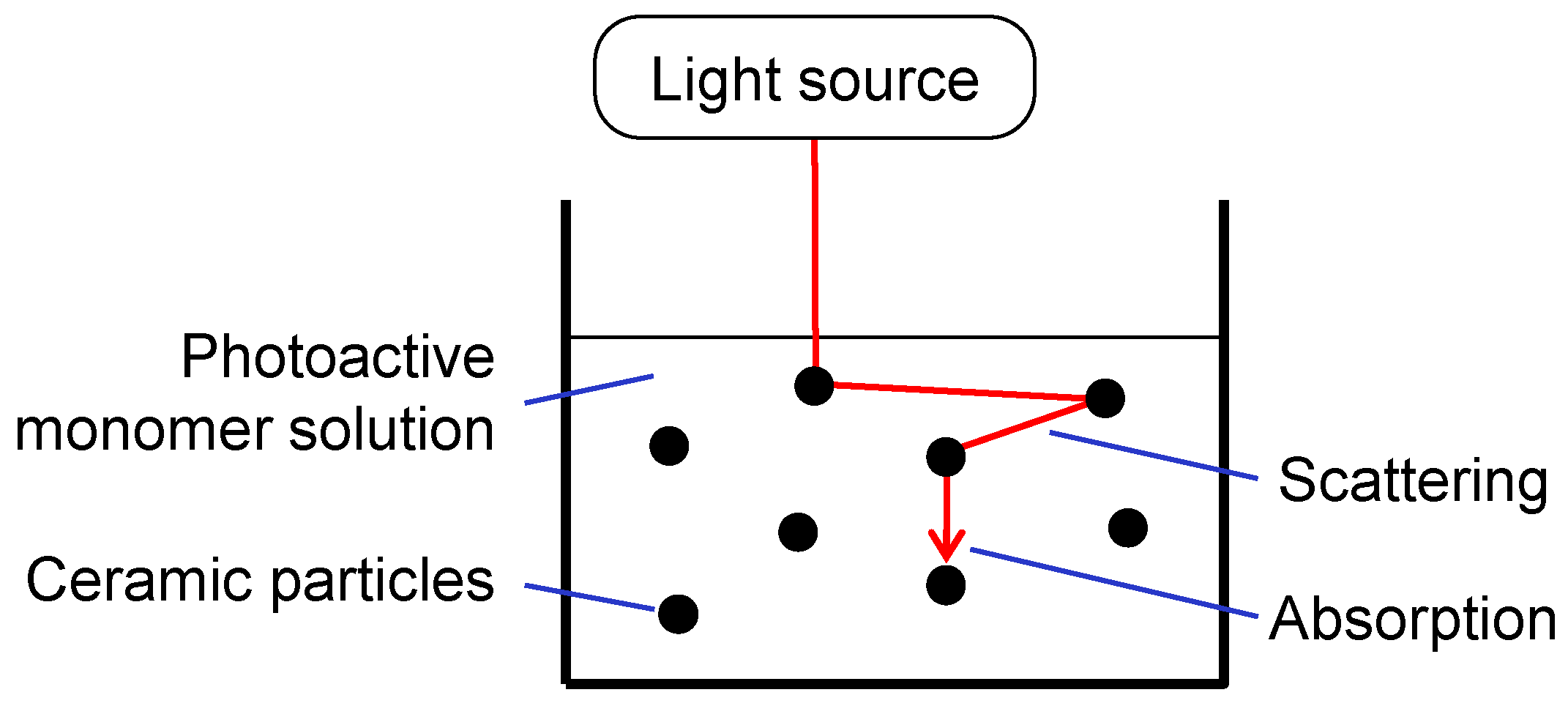
SLA employs an UV light beam that induces photopolymerization of a reactive suspension containing ceramic particles. These are dispersed in a suitable photopolymerizable resin in which a photoinitiator is dissolved. The three basic steps of the photopolymerization reaction are (i) initiation: the photoinitiator absorbs the photons and it cleaves to produce a free radical, (ii) propagation: the growing macro-radical becomes a cross linked gel at a relatively low degree of conversion, and (iii) termination: after time, termination starts to occur, mainly due to recombination and oxygen inhibition (see Figure 1).
Once polymerized, the photopolymer constitutes a rigid matrix around the ceramic particles and confers the cohesion to the green body. The organic phase is subsequently removed by an appropriate thermal treatment at low temperature (i.e., debinding). Then, the sintering of the part at high temperature ensures the final properties of the ceramic piece [21,22].
In the present work, 3D-printed alumina struts-based monoliths were produced via SLA. After their washcoating, a comparison of the catalytic performance in the selective catalytic reduction of nitrogen oxides (NOx) by NH3 was carried out and the results were compared with respect to a conventional washcoated cordierite honeycomb of 400 cpsi.

2. Materials and Methods

2.1. Design of the Structures and Geometrical Requirements

The closed-walls lattices were generated via a purpose-built 3D numerical tool developed in MATLAB R2019a (MathWorks, Natick, MA, USA) for the generation of periodic architectures made up of struts elements. The selected unit cell, corresponding in this case to a rotated cube (i.e., main diagonal of the cube aligned with the flow direction), was replicated in the space, forming datasets containing positions of the nodes and the connections. The produced nodes and connections were then converted into a STEP file, made up of spheres (for each node) and cylinders (for each connection) with adjustable diameters [23,24].
The lattice was then cropped into the desired shape using a commercial CAD software. Finally, the outer walls were built to close the external faces of the lattice and form a tubular architecture. Prior to the 3D printing, the geometry was converted into STL file.
One of the major advantages of additive manufacturing is the flexibility in choosing the dimensions of the structure to be manufactured and used. Main characteristics are the porosity ε and the strut diameter ds. By choosing these two parameters, the surface properties of the resulting catalyst are fixed in terms of specific as well as of wetted surface area. Figure 2 shows the wetted surface of a series of additively manufactured open lattice structures in respect to state-of-the-art honeycombs. The chosen dimensions are selected from the best performing ones in a preceding work [16] where different geometrical features were compared systematically in terms of reactivity as well as of pressure drop.
Looking at Figure 2, it is clear that the structure with thinner struts and lower porosity leads to higher wetted surface area, which is, however, a factor of 2 below the conventional honeycombs. In terms of reactivity, the additively manufactured structure with porosity ε = 80% and ds = 0.5 mm shows the best performance (Figure 3), closely followed by the 600 cpsi honeycomb (HC600). Since this honeycomb has three times higher wetted surface area, it requires also three times higher precious metal quantity (assuming similar dispersion of the precious metals on the outside layer of the surfaces). Interestingly, higher porosities and/or larger strut diameters directly affect the surface reactions, resulting in deficits with respect to the honeycombs, particularly at high gas velocities. Thus, efforts in additive manufacturing should focus on delivering thin struts, with a diameter of 0.5 mm and a moderate porosity of about 80%.
Keeping in mind the optimal configuration, in terms of geometric specifications, provided by the previous results [16], the subsequent 3D printing trials allowed us to select the optimal lattice configuration (see Figure 4) from a manufacturing point of view. To guarantee a good result in terms of printing quality and repeatability, preliminary investigations were performed to determine the minimum diameter of the struts that can be reproduced with the SLA technique employing the selected Al2O3-based slurry. Very thin struts, with a diameter of 0.20 mm, can be 3D printed (see chapter “Results and Discussion”), but the final sintered component is very fragile and difficult to handle. In particular, the subsequent coating with precious metals is very challenging to perform without damaging the substrate. Another geometric aspect that affects this phenomenon consists of the struts aspect ratio, defined as the length/diameter ratio. It has been experimented, in the context of the present study, that by keeping this parameter below 6, it is possible to guarantee both the printability of the structure and its handling for the following processes. Based on that preliminary experiment, the final configuration consists of a lattice with cells size of 2 mm and struts diameter of 0.55 mm. The lattice was generated inside a rectangular-shaped tube with 17 mm × 12 mm rectangular base and 54 mm height. The architecture has an internal specific surface area of 13.3 cm2·cm−3 and a macro porosity of 85%. For comparison, a state of art 400 cpsi honeycomb has a specific surface area of 28.7 cm2·cm−3 while a 600 cpsi is 34.5 cm2·cm−3. Prior to printing, the model was uniformly scaled up by 12% to compensate for the shrinkage occurring during the sintering and the resulting consolidation of the ceramic particles (i.e., porosity reduction).

2.2. 3D Printing

An Al2O3-based photosensitive slurry with a ceramic volume fraction of 30% was developed and employed for this project. Tri(propylene glycol) diacrylate (TPGDA, Allnex, Luxemburg) was used as monomer base to disperse α alumina particles (Nabalox NO 615-10, Nabaltec, Schwandorf, Germany) previously dried in a vacuum oven (−1 bar) at 150 °C for 2 h. Irgacure 819 (BASF, Ludwigshafen, Germany) was employed at 1.1 wt% (with respect to the diacrylate) as photoinitiator. The suspension was obtained via ball mixing for 24 h. Further details can be found in ref. [19,25].
The lattice geometries were 3D printed, with layer thicknesses of 50 μm, adopting the Digital Light Processing (DLP) technique in the “bottom-up” configuration through an industrial ceramic 3D printer specially designed to process highly viscous photosensitive ceramic suspensions (Admaflex 130, Admatec, The Netherlands). A schematic representation of the printing principle is shown in Figure 5.
The photosensitive ceramic slurry is transported below the build platform by means of a transparent polymeric film. The slurry that is not photopolymerized is recollected after the slice projection and transferred to the material depositor. The light source is positioned below the polymeric foil. The ceramic slurry, when invested by the UV light source, solidifies and attaches to the previous layers. The object then grows upside down attached to the build platform. The benefit of such a system is that a very gentle peel-off force stresses the object after a layer is solidified and the Z-stage moves up. This guarantees the printability of very thin struts without breaking them. Moreover, since the film is used just once, the printing surface is always new and not degraded by its use (e.g., UV irradiation and scratches).
The samples were finally thermally treated to firstly remove the organic binder (i.e., debinding) by heating up the samples to 500 °C at 1 °C·min−1 for 1 h and subsequently consolidate the ceramic phase (i.e., sintering) at 1600 °C for 2 h. Debinding and sintering were executed consecutively. The thermal treatment was selected from thermogravimetric (TGA/DSC) measurements. The selected temperature/time profile was implemented in air in a muffle furnace.

2.3. Washcoating with Catalytically Active Material

One 3D-printed alumina substrate (size, 12 mm × 17 mm × 54 mm; volume, 8 cm3; specific surface, 13.3 cm2·cm−3) and two conventional cordierite honeycomb substrates (M1 and M2; 400 cpsi; 12 mm × 17 mm × 50 mm; volume 10.3 cm3; specific surface 25.1 cm2·cm−3) were coated using a standard V2O5-WO3-TiO2 catalyst for selective catalytic reduction of NO by NH3 [26], as summarized in Table 1. The HC specimens were cut out from a monolith with the following dimensions (Corning GmbH, Germany): diameter 267 mm, length 178 mm, cell density 400 cpsi, wall thickness 7 mils (0.17 mm). The catalyst was obtained in powder form by impregnation of commercial 10 wt% WO3-TiO2 (CristalActive DT-52, kindly obtained from Cristal Global) with an aqueous solution of ammonium metavanadate (NH4VO3, assay ≥99.0%, Sigma-Aldrich, Burlington, MA, USA) followed by drying at 120 °C for 2 h and calcination in muffle furnace at 550 °C for 3 h. The powder was then suspended in water (3 eq. of catalytic material), sonicated for 10 min, and homogenized with a disperser for 5 min at 20,000 rpm (d-8, Miccra, DE). The monoliths were repeatedly immersed in the slurry and dried with an air blower to reach a loading of the active material of ca. 70–71 g∙L−1 (3D-printed and M1). One cordierite monolith (M2) was washcoated to obtain 124 g∙L−1, a typical value for a practical application. Finally, the monoliths were dried and calcined at 450 °C for 10 h in a muffle furnace. The washcoat loading was determined from the mass change of the substrate. The washcoat thickness was estimated from geometric considerations and taking into account the density of the catalyst powder (ca. 1–1.1 g·cm−3).

2.4. Catalytic Activity Tests

All washcoated monolithic cores were tested for NO selective catalytic reduction by NH3 in a heated quartz glass reactor [27] in a feed of 10 vol% O2, 5 vol% H2O, 500 ppm NO, 0–600 ppm NH3 with balance N2 at a gas hourly space velocity (GHSV = volumetric gas flow/volume of reactor occupied by the coated monolith, STP) of 50,000 h−1. The NOx conversion was calculated as XNO = 100∙([NOx]in − [NOx]out)/[NOx]in, where [NOx]in and [NOx]out are the NOx concentrations (NO+NO2) upstream and downstream of the catalyst ([NOx]in = 0). Online gas analysis of the reactor exhaust gas was carried out using a Fourier transform infrared spectrometer (Nexus, Thermo Fisher, Waltham, MA, USA) equipped with a 2 m heated transmission gas cell. The maximum NOx conversion was measured by increasing NH3 concentration in the feed from up to 600 ppm (NH3/NOx = 0–1.2) at each temperature at constant NO concentration in the feed. From the same set of measurements, the NOx conversion at 10 ppm NH3 slip was obtained, as well. The NOx conversion at 10 ppm NH3 slip can be significantly lower than the maximum NOx conversion, depending on the type of catalyst mass, catalyst geometry, and GHSV. To avoid unnecessarily high NH3 slip, NOx conversions at 10 ppm NH3 slip are often targeted for real applications [26,28].

3. Results and Discussion

As previously described, some preliminary 3D printing tests were performed to assess the capability of the employed SLA production process. Figure 6 left shows a green body with a struts diameter of 0.20 mm, a cell size of 1 mm, and a wall thickness of 0.55 mm. The printing result is very encouraging, since the component was printed without defects (i.e., cracks or delamination), the struts are intact, and the cells are not occluded. Nevertheless, the part turns out to be extremely fragile and very difficult to handle; thus, the coating with precious metals (washcoating) cannot be properly achieved without damaging the lattice. Moreover, as written previously, the best compromise between surface area and pressure drop (Figure 3) is obtained with a struts diameter of 0.5 mm and a porosity of about 80% (combining this two geometrical characteristics leads to a cell size of approx. 2 mm).
The right panel of Figure 6 shows the 3D-printed and sintered lattice in its final configuration ready to be washcoated with precious metals and employed for the conversion tests. The component undergoes a homogeneous volumetric shrinkage of about 12% during the heat treatment (debinding and sintering). 
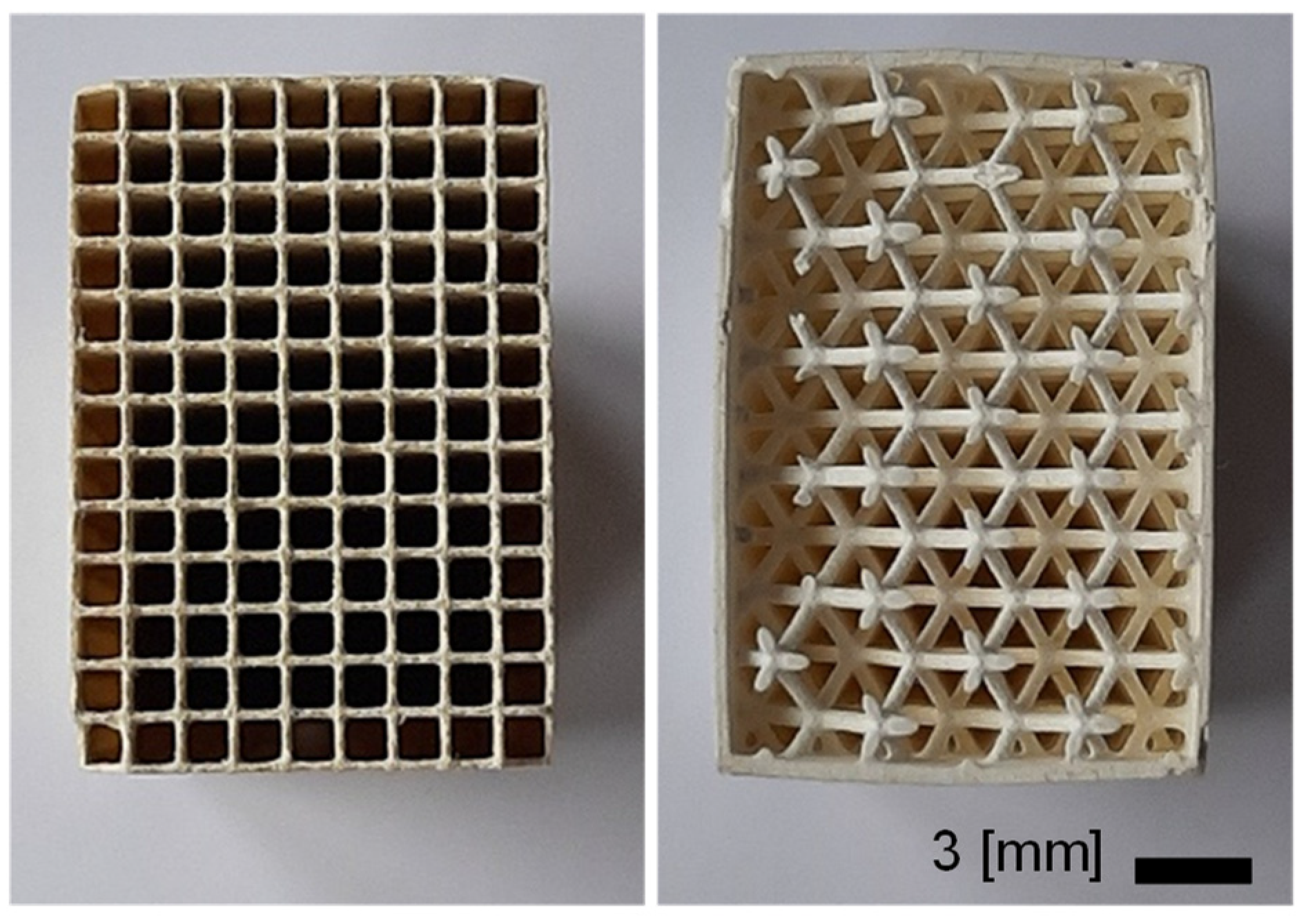
Figure 7 shows a traditional honeycomb catalyst (M1 in Table 1) and the 3D-printed lattice (3D-printed in Table 1). Both structures were washcoated with the same catalytically active material. The geometry of both honeycombs (M1 and M2 in Table 1) is the same (400 cpsi), and as shown in the Figure 7, the external dimensions of the tested specimens are equal.
Table 1 shows that the three samples were prepared using different washcoating characteristics. M1 and 3D-printed had the same volumetric mass loading, which resulted in an estimated half coating thickness of M1. M2 was thus prepared to obtain the same area loading and coating thickness of the 3D-printed, which resulted in around double the volumetric mass loading, i.e., 124 g∙L−1 against 70 g∙L−1. This is the standard loading of 400 cpsi cordierite monoliths for practical applications. Hence, M1 and M2 had around double specific surface compared to the 3D-printed one, while M2 and 3D-printed had the same catalyst mass per unit specific surface. It appears already clear that comparison of the monolithic pieces, honeycomb and 3D-printed, is not trivial when the same catalytically active phase is used.
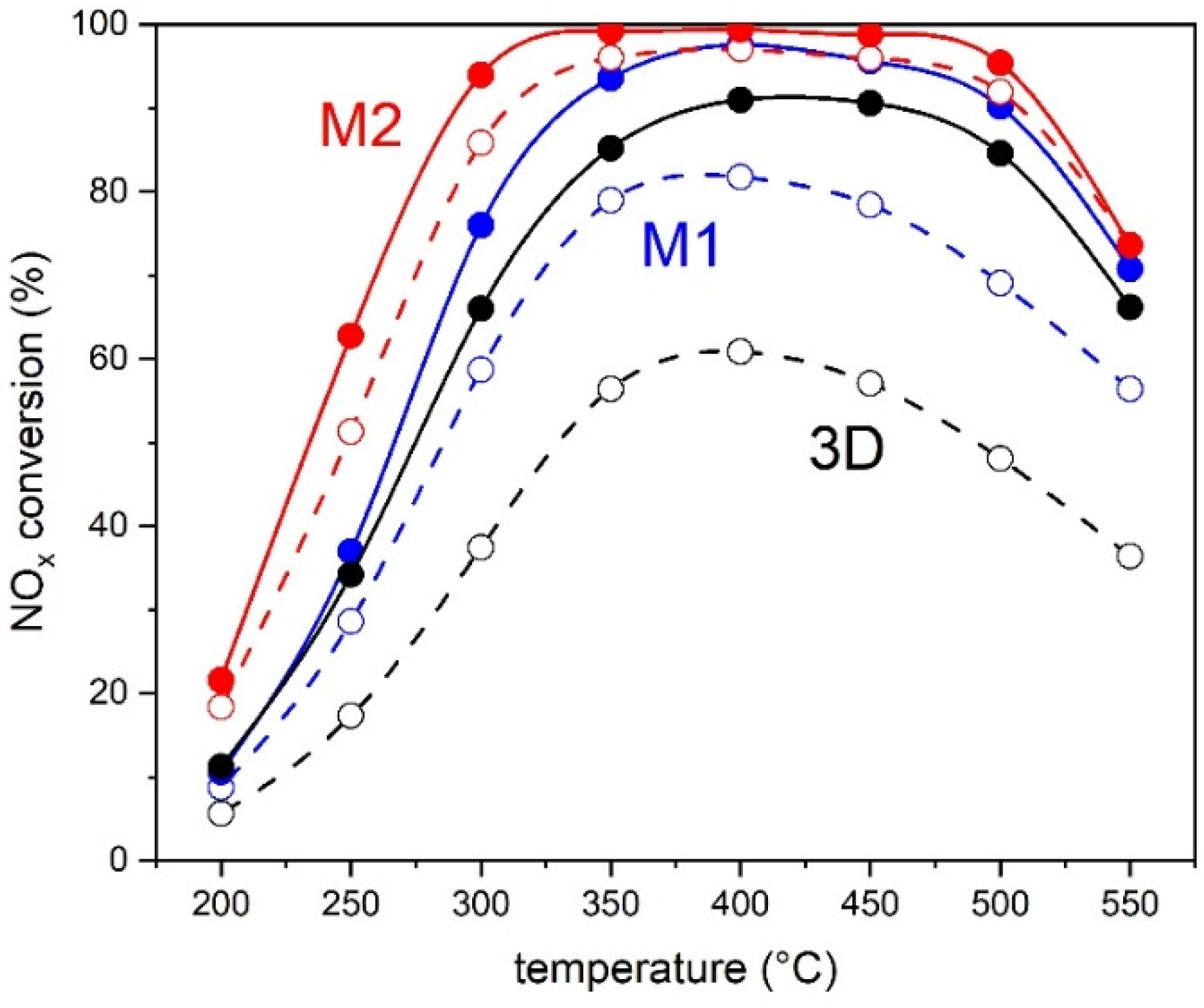
Figure 8 shows the NH3-SCR results for the three samples obtained at a GHSV of 50,000 h−1 for NOx conversion and NOx conversion at 10 ppm NH3 slip. Based on the characteristics mentioned above, M2 exhibited the highest NO conversion on the whole temperature range (200–550 °C). M1 was characterized by roughly half of the NO conversion of M2 below 300 °C, in agreement with its reduced (half) catalyst mass (see Table 1). The two samples also produced N2O above 400 °C (not shown), which is due to unselective NH3 oxidation. At 550 °C, M1 and M2 produced 20 ppm and 38 ppm, respectively. Under these conditions, the 3D-printed sample was the least active and was less active than sample M1, which was the most similar in terms of active mass load (approx. 70 g∙L−1). This becomes clear especially above 300 °C. For example, at 250 °C, M1 exhibited 48% NOx conversion while the 3D-printed exhibited 44%, and at 300 °C, the difference increased to 10% conversion. The lower levels of N2O observed for 3D-printed (13 ppm at 550 °C) reflect the lower catalytic activity of the sample.
The overall difference in performance between M1 and 3D-printed is not large when the maximum NOx conversion is considered. The values in Figure 8 are obtained by increasing the concentration of NH3 at isothermal conditions until maximum NOx conversion is obtained. However, the NOx conversion at 10 ppm NH3 slip is a better indicator of catalyst differences. In the same series of experiments performed to obtain the maximum NOx conversion, the NOx conversion value is also taken at which the concentration of NH3 downstream of the sample is ca. 10 ppm. This parameter was significantly higher for M1 at 250 °C (29% vs. 17%, ∆ = 12%) and the difference increased to 22% at 400 °C. This means that the value of 10 ppm NH3 slip was attained already at lower NOx conversion in the case of the 3D-printed sample and indicates that NH3 was overdosed; thus, the catalyst was not able to use efficiently all the NH3 that is in the feed under these conditions.
In order to perform a fairer comparison between 3D-printed sample and M1, 3D-printed was tested at lower GHSV conditions (20,200 h−1) by decreasing the total flow rate of the feed to the sample in the reactor. Note that the measurement was performed up to 400 °C in this case. Figure 8 demonstrates that under these conditions, NOx conversion at 300 °C increased significantly from 35% to 72% and reached 100% at 350 °C. Most importantly, the NH3 slip decreased and NOx conversion at 100 ppm NH3 slip increased to 55% at 250 °C and was practically identical to NOx conversion at 400 °C. This indicates that the testing conditions and the structure of the catalytic converter play an important role in defining the performance of the catalytically active phase. The nature of the washcoated catalyst is the same for the honeycomb and the 3D-printed samples, but the geometry of the monolith core is very different, producing different effects on catalytic activity for NO reduction by NH3, and NH3 storage conditions as revealed by the NOx conversion at 100 ppm NH3 slip. Comparison of such different structures is not straightforward but could be rationalized based on the following considerations.
Comparison of Figure 8 and Figure 9 reveals that 3D-printed sample was very active at GHSV = 20,200 h−1 and exhibited similar, if not better, NOx conversion values than sample M2, which had double active mass load (70 vs. 124 g·L−1). Table 2 shows that the comparison between 3D-printed and M2 is possible essentially because of geometric considerations, despite the very different GHSV at which the two samples were tested. At GHSV= 50,000 h−1, the volumetric load of the three samples is the same (13.9 mL∙cm−3∙s−1); the mass load is the same for M1 and 3D-printed and delivers the results of Figure 8, but it is very different from that of M2 because of the higher catalyst mass of M2; finally, 3D-printed has a double value of area load compared to M1 and M2 because of its specific surface (13.3 vs. 25.1 cm2mL−1). The value of mass load for 3D-printed decreases significantly when lower GHSV is used and thus volumetric load. It is also important to note that the value of area load decreases to 53% and 43% of the value obtained with GHSV = 50,000 h−1 (Table 2) when the calculation of the area load is made taking into account only the inner area of the lattice and the inner area of the lattice with the inner part of the outer wall, which is coated and thus participates in the reaction. The value decreases from 1.04 mL∙cm−2∙s−1 to 0.44 mL∙cm−2∙s−1 when the area of the lattice is considered together with the area of the walls. Therefore, the decrease in the GHSV from 3D-printed to the same area load of M1-M2 leads to very similar NO conversion levels. The slightly higher NO conversion values observed with 3D-printed and evident in Figure 9 can be ascribed to the explicit consideration of the washcoated area of the lattice and of the wall as well as to the higher turbulence generated by the 3D-printed structure.
The data indicate that the area load is a better comparison term than GHSV. Nevertheless, due to the low specific surface area of the 3D-printed structure of this work, the 3D structure requires twice the catalyst volume to attain the same NOx conversion. The higher turbulences in the 3D structure play a subordinate role in the SCR reaction and the disadvantage of the overall smaller surface area predominates. Therefore, 3D-printed structures of this type should be produced that exhibit higher specific surface and thus higher density of struts within the lattice, in order to be comparable to the honeycomb counterpart.

4. Conclusions

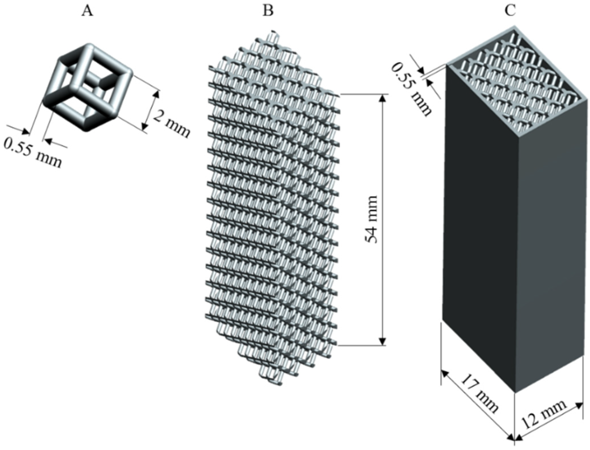
From the AM point of view, the study reports a tangible application of the SLA technique for the production of porous structures. It was actually possible to design, 3D print, and coat tubular lattices made of 2 mm cells and 0.55 mm diameter struts. It was also proved that it is even possible to print smaller cells, up to 1 mm with a struts diameter of 0.2 mm.
The reported catalysis results showed that the wetted surface area of the 3D-printed lattice is about half that of a traditional honeycomb. However, the reactivity of the lattice was found to be in line with that of traditional substrates. This is because the catalytic activity is favored by the turbulent flow within the intricate structure. Another advantage of 3D-printed lattice is that, since it has a smaller surface area, it also requires less noble metal to provide the same catalytic activity (the amount of the required precious metals can be fairly considered as proportional to the overall surface area of the catalyst).
The relatively slow NH3-SCR reaction is not suitable to demonstrate the advantages of the higher turbulence and mass transfer in the 3D-printed structures compared to conventional honeycombs monoliths. If the two catalyst substrates are operated with the same surface load (corresponding to a smaller GHSV of the 3D-printed structure because of the smaller specific surface), practically identical NOx conversions were achieved with both. The intrinsic, mass-related activity of the catalyst material is identical on both the substrates, i.e., the alumina substrate of the 3D-printed structure does not negatively influence the activity of NH3-SCR catalysts based on V2O5-WO3-TiO2.
Unfortunately, a possible advantage of these open structures could not be experimentally proven with the employed experimental setup. The conventional cordierite monoliths consist of individual channels that do not allow any significant gas exchange between them. This means that if the reducing agent is inhomogeneously distributed over the catalyst cross-section, this inhomogeneity remains frozen: cells with a reducing agent deficiency cannot provide their full NH3-SCR performance, others with an excess of reducing agent cause unnecessarily high NH3 slip. This inhomogeneous distribution of the reducing agent is one of the main problems in the practical application of the NH3-SCR process.
With open structures, there is a chance of some mixing over the catalyst cross-section. It is difficult to estimate how large the redirection of the model gas flow is in the present struts-based architectures, but it is unlikely to be very efficient. For a future development, it would certainly be better to have smaller surfaces that are slightly offset from each other. Such a geometry would also increase the specific surface area and thus allow higher volumetric loads. However, too complex, small structures are more difficult to coat with the active mass (i.e., washcoating) and are more difficult to handle due to their high fragility.

Author Contributions

Conceptualization, D.F., P.D.E., and A.O.; Data curation, O.S., F.C., M.P., D.F., and M.E.; Funding acquisition, P.D.E.; Investigation, O.S., F.C., M.P., D.F., M.E., P.D.E., and A.O.; Methodology, O.S., F.C., M.P., D.F., M.E., P.D.E., and A.O.; Project administration, D.F., P.D.E., and A.O.; Validation, O.S. and M.E.; Writing—original draft, O.S. and A.O.; Writing—review and editing, O.S. and A.O. All authors have read and agreed to the published version of the manuscript.

Funding

The project “Exhaust Aftertreatment System for the lowest environmental impact, Natural Gas powered delivery vehicle, Euro 7 and beyond (EAS7+)” has received funding from the Swiss federal Office for Environment and FPT Motorenforschung AG, contract No. UTF 584.13.18.

Institutional Review Board Statement

Not applicable.

Informed Consent Statement

Not applicable.

Data Availability Statement

Data presented in this study are available in https://repository.supsi.ch/ (accessed on 1 September 2021).

Conflicts of Interest

The authors declare no conflict of interest.

References

  1. Nijhuis, T.A.; Beers, A.E.; Vergunst, T.; Hoek, I.; Kapteijn, F.; Moulijn, J.A. Preparation of monolithic catalysts. Catal. Rev. 2001, 43, 345–380. [Google Scholar] [CrossRef]
  2. Patcas, F.C.; Garrido, G.I.; Kraushaar-Czarnetzki, B. CO oxidation over structured carriers: A comparison of ceramic foams, honeycombs and beads. Chem. Eng. Sci. 2007, 62, 3984–3990. [Google Scholar] [CrossRef]
  3. Lucci, F.; Della Torre, A.; Montenegro, G.; Kaufmann, R.; Eggenschwiler, P.D. Comparison of geometrical, momentum and mass transfer characteristics of real foams to Kelvin cell lattices for catalyst applications. Int. J. Heat Mass Transf. 2017, 108, 341–350. [Google Scholar] [CrossRef] [Green Version]
  4. Busse, C.; Freund, H.; Schwieger, W. Intensification of heat transfer in catalytic reactors by additively manufactured periodic open cellular structures (POCS). Chem. Eng. Process. Process. Intensif. 2018, 124, 199–214. [Google Scholar] [CrossRef]
  5. Giani, L.; Groppi, G.; Tronconi, E. Mass-transfer characterization of metallic foams as supports for structured catalysts. Ind. Eng. Chem. Res. 2005, 44, 4993–5002. [Google Scholar] [CrossRef]
  6. Pangarkar, K.; Schildhauer, T.J.; van Ommen, J.R.; Nijenhuis, J.; Kapteijn, F.; Moulijn, J.A. Structured packings for multiphase catalytic reactors. Ind. Eng. Chem. Res. 2008, 47, 3720–3751. [Google Scholar] [CrossRef]
  7. Bracconi, M.; Ambrosetti, M.; Maestri, M.; Groppi, G.; Tronconi, E. A fundamental investigation of gas/solid mass transfer in open-cell foams using a combined experimental and CFD approach. Chem. Eng. J. 2018, 352, 558–571. [Google Scholar] [CrossRef]
  8. Gaiser, G.; Oesterle, J.; Braun, J.; Zacke, P. The progressive spin inlet–homogeneous flow distributions under stringent conditions. SAE Trans. 2003, 112, 605–619. [Google Scholar]
  9. Zygourakis, K. Transient operation of monolith catalytic converters: A two-dimensional reactor model and the effects of radially nonuniform flow distributions. Chem. Eng. Sci. 1989, 44, 2075–2086. [Google Scholar] [CrossRef]
  10. von Rickenbach, J.; Lucci, F.; Eggenschwiler, P.D.; Poulikakos, D. Pore scale modeling of cold-start emissions in foam based catalytic reactors. Chem. Eng. Sci. 2015, 138, 446–456. [Google Scholar] [CrossRef]
  11. Eggenschwiler, P.D.; Tsinoglou, D.N.; Seyfert, J.; Bach, C.; Vogt, U.; Gorbar, M. Ceramic foam substrates for automotive catalyst applications: Fluid mechanic analysis. Exp. Fluids 2009, 47, 209–222. [Google Scholar] [CrossRef]
  12. Della Torre, A.; Montenegro, G.; Onorati, A.; Tabor, G. CFD characterization of pressure drop and heat transfer inside porous substrates. Energy Procedia 2015, 81, 836–845. [Google Scholar] [CrossRef] [Green Version]
  13. Koltsakis, G.C.; Katsaounis, D.K.; Samaras, Z.C.; Naumann, D.; Saberi, S.; Böhm, A.; Markomanolakis, I. Development of Metal Foam based Aftertreatment System on a Diesel Passenger Car; SAE Technical Paper 2008-01-0619; SAE International: Mobilus, PA, USA, 2008. [Google Scholar]
  14. Lu, T.J.; Stone, H.A.; Ashby, M.F. Heat transfer in open-cell metal foams. Acta Mater. 1998, 46, 3619–3635. [Google Scholar] [CrossRef]
  15. Ferroni, C.; Bracconi, M.; Ambrosetti, M.; Maestri, M.; Groppi, G.; Tronconi, E. A Fundamental Investigation of Gas/Solid Heat and Mass Transfer in Structured Catalysts Based on Periodic Open Cellular Structures (POCS). Ind. Eng. Chem. Res. 2021. [Google Scholar] [CrossRef]
  16. Papetti, V.; Eggenschwiler, P.D.; Della Torre, A.; Lucci, F.; Ortona, A.; Montenegro, G. Additive manufactured open cell polyhedral structures as substrates for automotive catalysts. Int. J. Heat Mass Transf. 2018, 126, 1035–1047. [Google Scholar] [CrossRef]
  17. Ortona, A.; D’Angelo, C.; Gianella, S.; Gaia, D. Cellular ceramics produced by rapid prototyping and replication. Mater. Lett. 2012, 80, 95–98. [Google Scholar] [CrossRef]
  18. Santoliquido, O.; Bianchi, G.; Dimopoulos Eggenschwiler, P.; Ortona, A. Additive manufacturing of periodic ceramic substrates for automotive catalyst supports. Int. J. Appl. Ceram. Technol. 2017, 14, 1164–1173. [Google Scholar] [CrossRef]
  19. Santoliquido, O.; Colombo, P.; Ortona, A. Additive Manufacturing of ceramic components by Digital Light Processing: A comparison between the “bottom-up” and the “top-down” approaches. J. Eur. Ceram. Soc. 2019, 39, 2140–2148. [Google Scholar] [CrossRef]
  20. König, R.; Spaggiari, M.; Santoliquido, O.; Principi, P.; Bianchi, G.; Ortona, A. Micropollutant adsorption from water with engineered porous ceramic architectures produced by additive manufacturing and coated with natural zeolite. J. Clean. Prod. 2020, 258, 120500. [Google Scholar] [CrossRef]
  21. Bandyopadhyay, A.; Bose, S. (Eds.) Additive Manufacturing; CRC Press: Boca Raton, FL, USA, 2019. [Google Scholar]
  22. Bae, C.J.; Ramachandran, A.; Chung, K.; Park, S. Ceramic stereolithography: Additive manufacturing for 3D complex ceramic structures. J. Korean Ceram. Soc. 2017, 54, 470–477. [Google Scholar] [CrossRef] [Green Version]
  23. Pelanconi, M.; Rezaei, E.; Ortona, A. Cellular ceramic architectures produced by hybrid additive manufacturing: A review on the evolution of their design. J. Ceram. Soc. Jpn. 2020, 128, 595–604. [Google Scholar] [CrossRef]
  24. Pelanconi, M.; Ortona, A. Review on the design approaches of cellular architectures produced by additive manufacturing. In International Conference on Additive Manufacturing in Products and Applications; Springer: Cham, Switzerland, 2020; pp. 52–64. [Google Scholar]
  25. Santoliquido, O.; Camerota, F.; Ortona, A. The influence of topology on DLP 3D printing, debinding and sintering of ceramic periodic architectures designed to replace bulky components. Open Ceram. 2021, 5, 100059. [Google Scholar] [CrossRef]
  26. Marberger, A.; Elsener, M.; Ferri, D.; Kröcher, O. VOx surface coverage optimization of V2O5/WO3-TiO2 SCR catalysts by variation of the V loading and by aging. Catalysts 2015, 5, 1704–1720. [Google Scholar] [CrossRef]
  27. Kleemann, M.; Elsener, M.; Koebel, M.; Wokaun, A. Investigation of the ammonia adsorption on monolithic SCR catalysts by transient response analysis. Appl. Catal. B Environ. 2020, 27, 231–242. [Google Scholar] [CrossRef]
  28. Koebel, M.; Elsener, M.; Kleemann, M. Urea-SCR: A promising technique to reduce NOx emissions from automotive diesel engines. Catal. Today 2000, 59, 335–345. [Google Scholar] [CrossRef]
Figure 1. Schematic representation of the scattering phenomenon occurring when a ceramic slurry is invested by photons.
Applsci 11 08239 g001
Figure 2. Wetted surface area (Sw) by the gas flow of three additively manufactured structures based on a rotated cube elementary cell (cubic 45) for different struts diameter (ds), porosities (ε), and cell size (Ls) in comparison with two state-of-the-art honeycombs (HC) with different cpsi (i.e., 400 and 600). Data source [16].
Applsci 11 08239 g002
Figure 3. Conversion efficiency (η) vs. gas flow speed (Vin) of three additively manufactured structures based on a rotated cube elementary cell (cubic 45) for different struts diameter (ds) and porosities (ε) in comparison with two state-of-the-art honeycombs (HC) with different cpsi (i.e., 400 and 600). All measurements were performed at high exhaust gas temperatures and under stationary conditions. Thus, the catalyst was operating in the mass transfer limited regime. Data source [16].
Applsci 11 08239 g003
Figure 4. CAD file of the developed architecture: (A) rotated cube unit cell; (B) cell replication; (C) tubular lattice.
Applsci 11 08239 g004
Figure 5. Schematic representation of the industrial ceramic 3D printer.
Applsci 11 08239 g005
Figure 6. (left): 3D-printed closed-walls lattice, the base cells correspond to a rotated cube with a struts diameter of 0.20 mm, a cell length of 1 mm, and a wall thickness of 0.55 mm. As a reference, a sewing needle with a diameter of about 0.4 mm is placed on the component. (right): 3D-printed and sintered closed-walls lattice in its final configuration, the base cells correspond to a rotated cube with a struts diameter of 0.55 mm and a cell length of 2 mm.
Applsci 11 08239 g006
Figure 7. (left): washcoated cordierite honeycomb (M1); (right): washcoated 3D-printed alumina lattice.
Applsci 11 08239 g007
Figure 8. Maximum NOx conversion (solid lines) and NOx conversion at 10 ppm NH3 slip (dashed lines) of the three samples M1, M2, and 3D-printed.
Applsci 11 08239 g008
Figure 9. Maximum NOx conversion (solid lines) and NOx conversion at 10 ppm NH3 slip (dashed lines) of sample 3D printed at GHSV = 50,000 h−1 and GHSV = 22,200 h−1.
Applsci 11 08239 g009
Table 1. Characteristics of the three monolith cores studied for NH3-SCR.
EntryCatalyst MassSpecific SurfaceWashcoat Thickness c
g·L−1 amg·cm−2 bcm2·cm−3µm
M1712.825.122
M21245.025.138
3D-printed705.313.340
a per unit volume; b per unit specific surface; c estimated from geometric considerations.
Table 2. Characteristics of the three monolith cores.
EntryGHSVVolumetric LoadMass LoadArea Load
h−1mL·cm−3·s−1mL·g−1·s−1mL·cm−2·s−1
M150,00013.919522
M250,00013.911138
3D-printed50,00013.919840
20,2005.680 a, 100 b0.44 a, 0.55 b
a taking into account only the area of the lattice; b taking into account also the inner area of the wall.
Publisher’s Note: MDPI stays neutral with regard to jurisdictional claims in published maps and institutional affiliations.

