Article

The Synthesis of Aluminum Matrix Composites Reinforced with Fe-Al Intermetallic Compounds by Ball Milling and Consolidation

by
Roberto Ademar Rodríguez Díaz
1,*,
Sergio Rubén Gonzaga Segura
2,
José Luis Reyes Barragán
3,
Víctor Ravelero Vázquez
3,
Arturo Molina Ocampo
2,
Jesús Porcayo Calderón
4,
Héctor Cruz Mejía
5,
Carlos Alberto González Rodríguez
5 and
Jesús Israel Barraza Fierro
6
1
Departamento de Ingeniería de Materiales, Tecnológico Nacional de México, Tecnológico de Estudios Superiores de Coacalco, Coacalco de Berriozábal 55700, Mexico
2
Centro de Investigación en Ingeniería y Ciencias Aplicadas–(IICBA), Universidad Autónoma del Estado de Morelos, Cuernavaca 62209, Mexico
3
Departamento de Ingeniería en Diseño, Universidad Politécnica de la Zona Metropolitana de Guadalajara, Tlajomulco de Zúñiga 45640, Mexico
4
Departamento de Ingeniería Química y Metalurgia, Universidad de Sonora, Hermosillo 83000, Mexico
5
División de Ingeniería en Nanotecnología, Universidad Politécnica del Valle de México, Tultitlan 54910, Mexico
6
Escuela de Preparatoria, Universidad La Salle Nezahualcóyotl, Ciudad de México 57300, Mexico
*
Author to whom correspondence should be addressed.
Submission received: 21 August 2021 / Revised: 15 September 2021 / Accepted: 16 September 2021 / Published: 24 September 2021

Abstract

:
In this study, a nano-composite material of a nanostructured Al-based matrix reinforced with Fe40Al intermetallic particles was produced by ball milling. During the non-equilibria processing, the powder mixtures with the compositions of Al-XFe40Al (X = 5, 10, and 15 vol. %) were mechanically milled under a low energy regime. The processed Al-XFe40Al powder mixtures were subjected to uniaxial pressing at room temperature. Afterward, the specimens were subjected to a sintering process under an inert atmosphere. In this thermal treatment, the specimens were annealed at 500 °C for 2 h. The sintering process was performed under an argon atmosphere. The crystallite size of the Al decreased as the milling time advanced. This behavior was observed in the three specimens. During the ball milling stage, the powder mixtures composed of Al-XFe40Al did not experience a mechanochemical reaction that could lead to the generation of secondary phases. The crystallite size of the Al displayed a predominant tendency to decrease during the ball milling process. The microstructure of the consolidated specimens indicated a uniform dispersion of the intermetallic reinforcement phases in the Al matrix. Moreover, according to the Vickers microhardness tests, the hardness varied linearly with the increase in the concentration of the Fe40Al intermetallic phase present in the composite material. The presented graphs indicate that the hardness increased almost linearly with the increasing dislocation density and with the reduction in grain sizes (both occurring during the non-equilibria processing). The microstructural and mechanical properties reported in this paper provide the aluminum matrix composite materials with the ideal conditions to be considered candidates for applications in the automotive and aeronautical industries.

1. Introduction

Al-based alloys are widely used as parts and components in the automotive and aerospace industry sectors due to their high ductility, specific strength, formability, and stiffness [1]. However, both pure Al and Al alloys possess low hardness and poor wear resistance. A well-known strategy to improve the wear resistance of Al and Al alloys is to produce Al composites. In this sense, it is well known that Al composites provide better wear resistance and improved bulk mechanical properties [2]. In particulate metal matrix composites (MMCs), the function of reinforcement particles is to strengthen the metal matrix. The mechanical behavior of the MMCs is greatly influenced by the properties of the matrix and reinforcement, volume fraction, their distribution, and size of reinforcement, as well as the interfacial strength between the matrix and reinforcement [1]. Adequate distribution of the particulate reinforcement in the metal matrix can be attained by the ball milling technique [3,4,5,6,7,8].
Aluminum matrix composites have been produced using two methods—liquid state processing (ex-stir casting) and solid-state processing (powder metallurgy, mechanical alloying). In the powder metallurgy processing method, the Al matrix and reinforcement are mixed in order to be compacted with a subsequent sintering process to gain strength. Aluminum MMCs are typically reinforced by oxides or ceramic particles. Considering that in ex situ processing, the reinforcement is added externally to the liquefied metal, problems of wettability and particle agglomeration needed to be resolved [9]. In this regard, the powder metallurgy method emerged with the aim of avoiding wettability and agglomeration problems and promoting a uniform dispersion of reinforcement in the Al matrix. Another strategy to counter the disadvantages of utilizing ex situ processing is to use phases other than ceramics as reinforcements. For example, intermetallic compounds could be considered candidate materials to reinforce Al matrix composites since ordered intermetallic compounds based on the aluminides of transition metals, such as Fe, Ni, Nb, Ti, and Co, have been assessed and studied for their potential application as structural materials at medium and high temperatures [10]. Moreover, the Al contents of these compounds induce the formation of a passive layer of Al oxide, which is responsible for very good corrosion and oxidation resistance at elevated temperatures [11]. Iron aluminides of the type Fe-Al and Fe3Al exhibit excellent mechanical resistance at high temperatures, low densities, high melting points, and good structural stability; however, efforts were applied to enhance the ductility and impact resistance of these compounds [12].
In terms of producing an MMC with improved mechanical properties along with low density, intermetallic compounds are very suited to these purposes. For example, the intermetallic phases of the Al-Ca binary alloy system are among the materials that can produce very light metal matrix composites, as these phases are extremely low in density [13]. The mechanical resistance of MMCs is significantly influenced by the interfacial strength between the matrix and reinforcement, which depends on the wettability between the metal and reinforcing particles. In this sense, it has been reported that intermetallics can be wetted by molten metal without difficulty. Additionally, they exhibit comparable mechanical behavior and a coefficient of thermal expansion closer to that of Al when compared to hard ceramic phases [14]. Therefore, in recent times, intermetallics based on Ni-Al and Ti-Al systems have been investigated as a new type of reinforcement for MMCs [15,16,17,18]. It is worth noting that the stiffness and wear behavior of the MMCs can be enhanced by the addition of intermetallics.
Thus, the purpose of this investigation was to take into account the advantages provided by the powder metallurgy route and the excellent properties that intermetallic compounds possess, in order to fabricate Al matrix composites reinforced with intermetallics of the Fe-Al system. Another goal was to analyze and study the influence of the processing parameters on the microstructure and hardness of the composites in order to achieve desired properties for automotive or aeronautic applications.

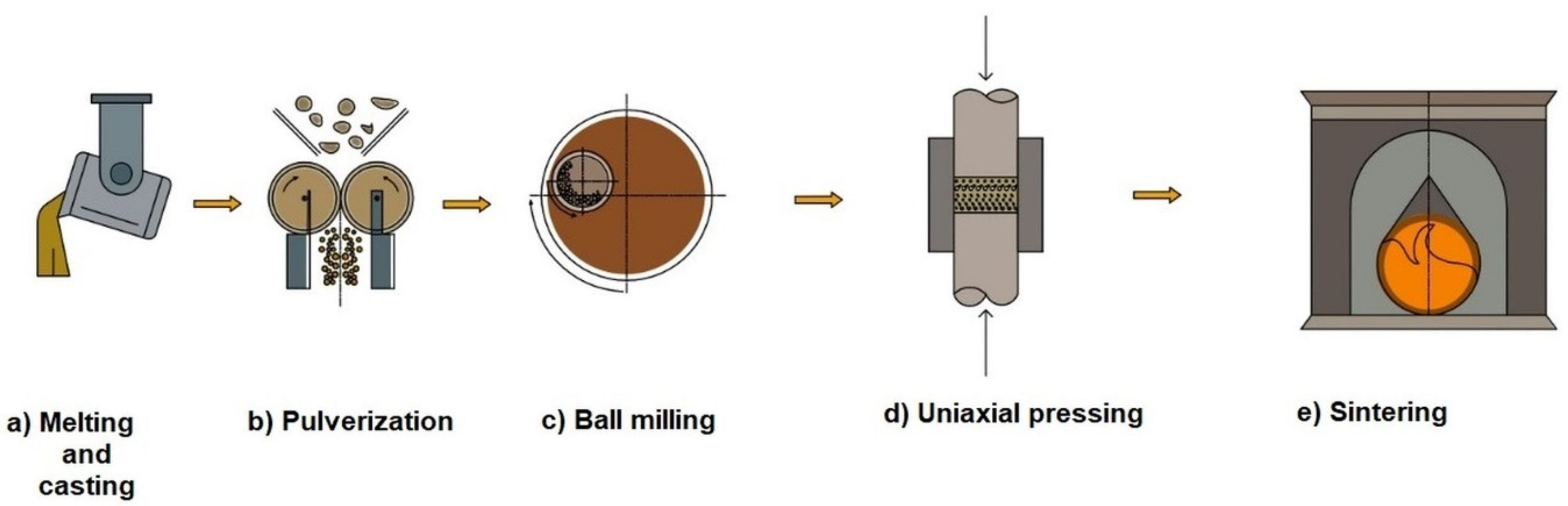
2. Materials and Methods

Processing route. The stages that were carried out in the processing route developed in this work are described below.
First, cast ingots of binary Fe40Al intermetallic compound were prepared using a high-frequency induction furnace at around 1500 °C, as shown in Figure 1a. High purity (99.9%) Fe and Al were placed inside a silicon carbide crucible for induction melting. The molten Fe–40 wt.% Al (labeled Fe40Al hereafter) alloy was poured into a rectangular parallelepiped steel mold and subsequently solidified as it cooled until it reached room temperature; these cooling conditions resulted in a coarse-grained microstructure. Then, in order to pulverize the ingots of the intermetallic compound, small pieces of the ingot with approximate measurements of 1 cm in height × 1 cm in length × 0.5 cm in width were cut. Then, these small ingot pieces were mechanically struck with a hammer, taking advantage of the fragility of the Fe40Al intermetallic compound in order to obtain a powder of this material with a particle size of less than 1 mm. Subsequently, the intermetallic composition powders were subjected to mechanical milling, and thus, their final size was obtained at this stage (see a schematic representation in Figure 1b). After, the powder mixture of Al and Fe40Al was subjected to planetary ball milling for various periods in order to reduce the particle sizes of both phases, obtain a uniform distribution of the Fe40Al intermetallic compound in Al, and induce the homogenization of the chemical elements in the powder mixture (see the illustrative image in Figure 1c). Then, the powder mixture of the Al and Fe was uniaxially pressed at room temperature in a cylindrical mold, as shown in Figure 1d. Subsequently, the green compacts obtained by uniaxial pressing were subjected to a sintering process in a conventional furnace under an argon atmosphere (see the illustration presented in Figure 1d).
The processing parameters of each of the stages involved in the processing route developed in the present work are described as follows.
Materials. The elemental powders of metallic Al and intermetallic Fe40Al (99.9% purity) were blended in a mortar—three-particle volume fractions of 5, 10, and 15% of Fe40Al intermetallic particles, were added to the aluminum powder.
Composite powder. The powder mixture was introduced, under an argon atmosphere, to a hardened steel vial with balls of the same material. Analytical grade methyl alcohol, used as a process control agent, was added at a ratio of 0.003 mL per gram of mixture. Later, the mixture was mechanically milled by utilizing a planetary mill at a speed of 250 RPM during different milling times: 0.5, 1, 2, 4, 6, and 8 h. During the ball milling tests, a balls-to-powder weight ratio of 10:1 was employed.
Consolidation of composite powders. The powder mixture that was milled for 8 h was uniaxially pressed by using a pressure of 15 tons with a hydraulic press. The resulting compacts possessed a diameter of 3/8 in and ¼ in of height. Then, the green compacts were sintered at 500 °C for 2 h with subsequent cooling inside the furnace.
Characterizations. The evolution of the morphology, the particle size, and the distribution of the chemical elements of the powder mixture were analyzed in a scanning electron microscope (SEM, Stereoscan 440), which was connected to software for energy dispersive spectroscopy (EDS). X-ray diffraction analysis was performed to determine and identify the crystalline structure of the different phases that remained or were formed during milling, as well as to determine the crystallite size, crystalline state transitions, and the lattice parameters from the X-ray diffraction peaks. To perform this analysis, a Bruker D2 Phaser Diffractometer D500 was utilized, in which a voltage of 30 kV was applied with a current of 20 mA. The samples were scanned with a filter of CuKα radiation with a wavelength of λ = 1.5418 Å, using a step of 0.020°/0.6 s in a range of 20° to 80°. Vickers microhardness measurements were performed in a Future-Tech Corp FM 700 microhardness tester to determine the microhardness of the sintered samples.

3. Results

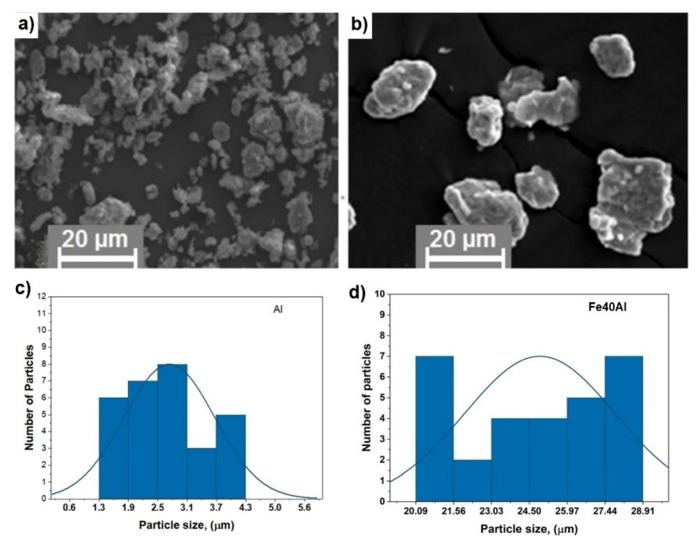
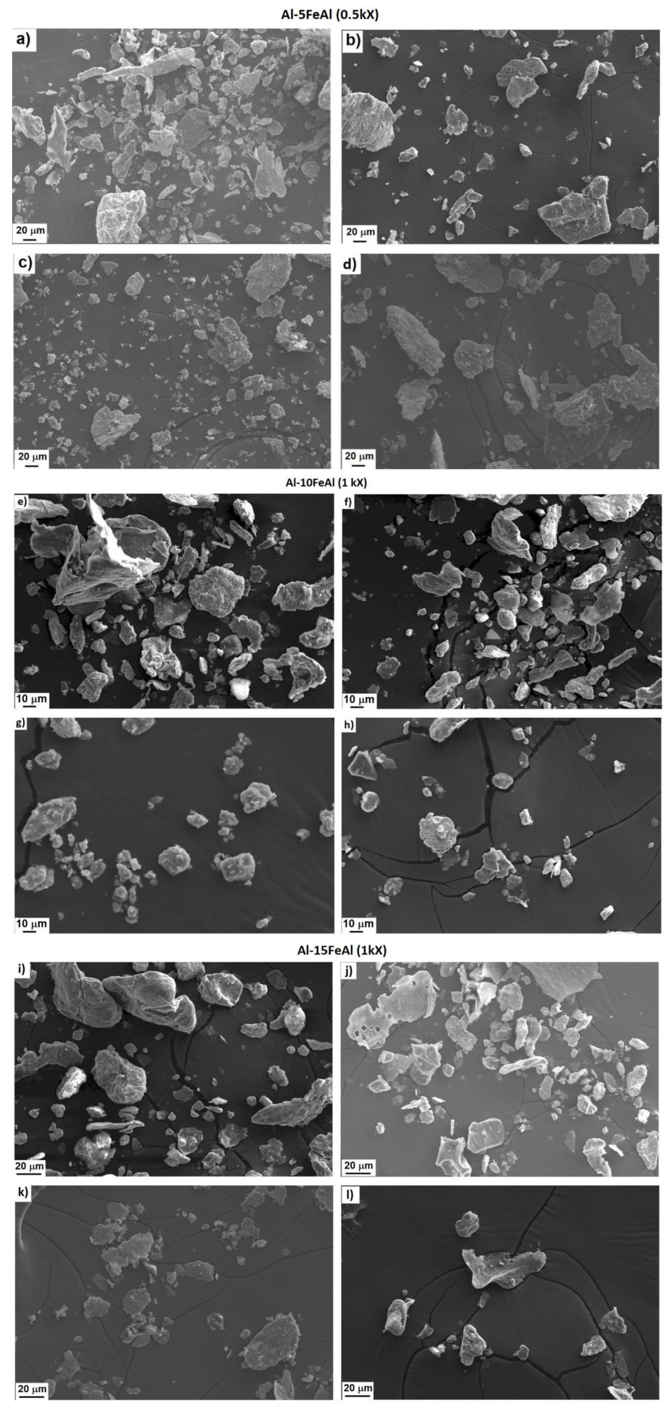
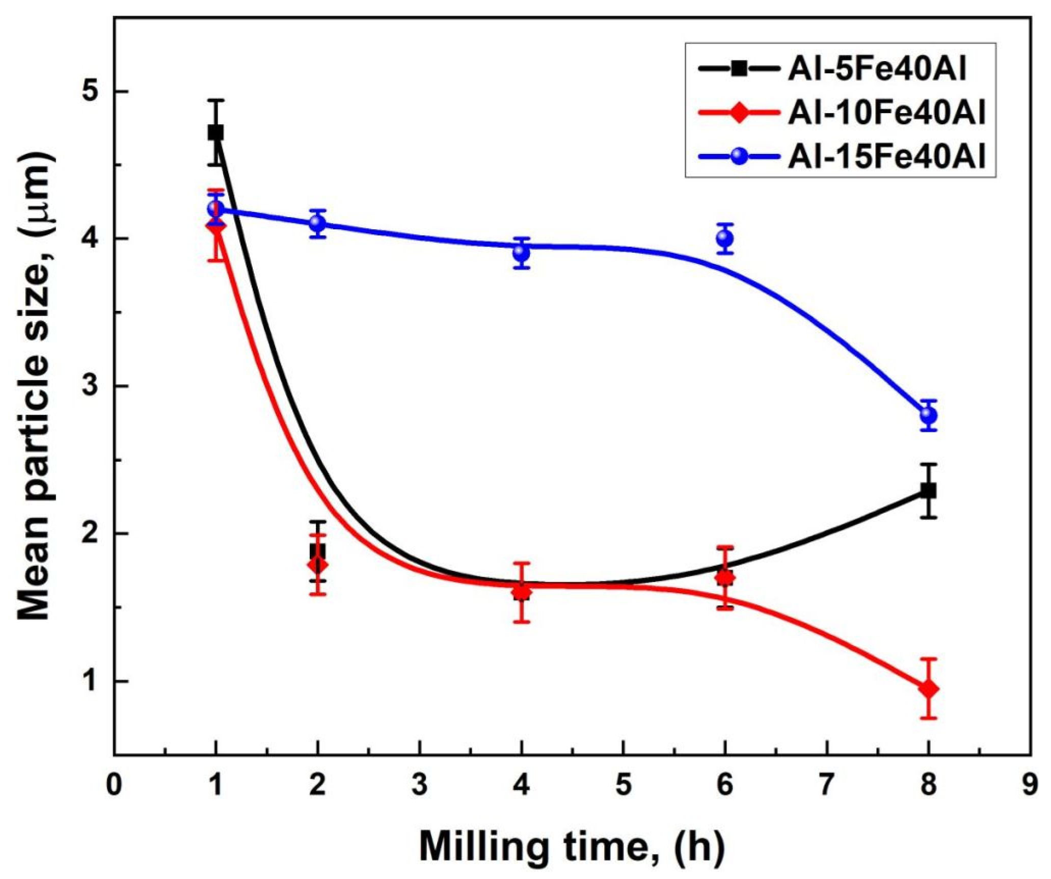
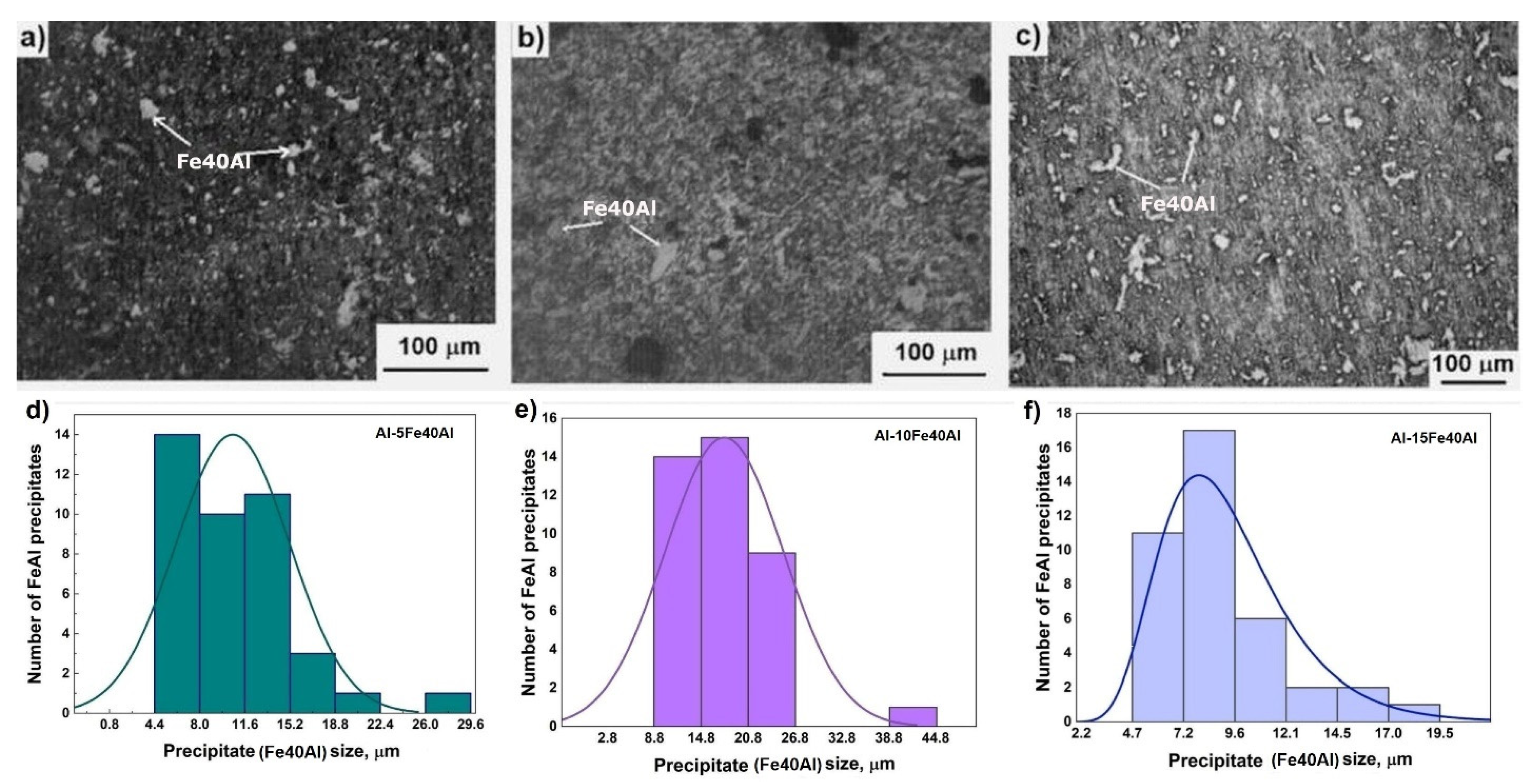
3.1. Microstructural Analysis by Scanning Electron Microscopy

Figure 2 presents the morphology of the elemental starting powders before the ball milling process. These powders correspond to Al and Fe40Al, respectively. Figure 2a displays the irregular-shaped particles of Al (with a mean particle size of 2.7 microns ± 0.95). Figure 2b exhibits the irregular-shaped Fe40Al intermetallic particles (with a mean particle size of 27 microns ± 2.9).
Figure 3 presents the evolution of the particle morphology and size of the powder mixtures of Al-5Fe40Al, Al-10Fe40Al, and Al-15Fe40Al respectively. Aiming to improve the visibility and synthesize the results of the particle size, the micrographs corresponding to 0, 2, 4, and 8 h of milling taken from each composition (Al-5Fe40Al, Al-10Fe40Al, and Al-15Fe40Al), are presented in one figure. The scanning electron micrographs show that the particle size decreased as the milling time advanced from 0 to 8 h in the cases of the Al-10Fe40Al and Al-15Fe40Al powder mixtures. However, the particle size of Al-5Fe40Al underwent a progressive diminution from the beginning to the end of the processing. In addition, according to these micrographs, the particle morphology remained irregular.
In Figure 4, the particle size variation of the Al-5Fe40Al composite powder is presented. It can be observed that the mean particle size decreased from around 4.7 microns to 1.6 microns as the powder mixture was milled from 1 h to 4 h. Between 4 h and the end of the milling process, the particle size increased from 1.6 µm to 2.4 µm. This behavior could be related to the predominance of welding among the particles. The size ranges of the powder composite mixtures exhibited a slight tendency to narrow with the advancement of the processing time.
Additionally, in Figure 4, the particle size of the Al-10Fe40Al powder mixture and the standard deviation as a function of the milling period are presented. This plot shows that the particle size predominantly diminished from about 4.1 µm to 0.8 µm as the milling time progressed from 1 h to 8 h. The size ranges related to the standard deviation of the powder composite mixtures exhibited a very slight trend to decrease with the advancement of the ball milling time.
Figure 4 also shows the particle size of the Al-15Fe40Al powder mixture. In this plot, the particle size of the Al-15Fe40Al powder mixture decreased from 4.2 µm at 0 h to 2.8 µm at 8 h of ball milling.
Similarly, the particle size distributions were applied to determine the mean particle size and the size range of the powder particles in each specimen. The size ranges of the powder composite mixtures suggest an almost imperceptible propensity to decrease as the ball milling period progressed.
It is evident that the particle size variation as a function of milling time exhibited a similar trend for the processing of the three powder mixtures (Al-5Fe40Al, Al-10Fe40Al, and Al-15Fe40Al). This tendency indicates that extended milling times yield a more uniform size of powders and smaller mean particle sizes.
Since the constituents of a powder mixture are ductile–brittle components, in this case, at the beginning of milling, the irregular shapes of the ductile aluminum particles were transformed into a flat flake morphology by the ball–powder–ball collisions, while the fragile particles corresponding to the Fe40Al intermetallic compound were fragmented. These brittle Fe40Al particles tend to be occluded by ductile aluminum particles and settle in interlamellar spacings. As the mechanical milling time progresses, the ductile aluminum particles are hardened by the mechanical workings, and the lamellae become convoluted and refined. As the grinding process takes place, the lamellae become more refined, the interlamellar spacing decreases, and, in this case, the brittle intermetallic particles were uniformly distributed throughout the ductile aluminum matrix. However, if the brittle constituent is soluble, then the alloying process occurs between the brittle and ductile components, tending towards chemical homogeneity [19]. In this case, the Fe element from the Fe40Al intermetallic particles was solubilized in the Al matrix progressively during the milling process.

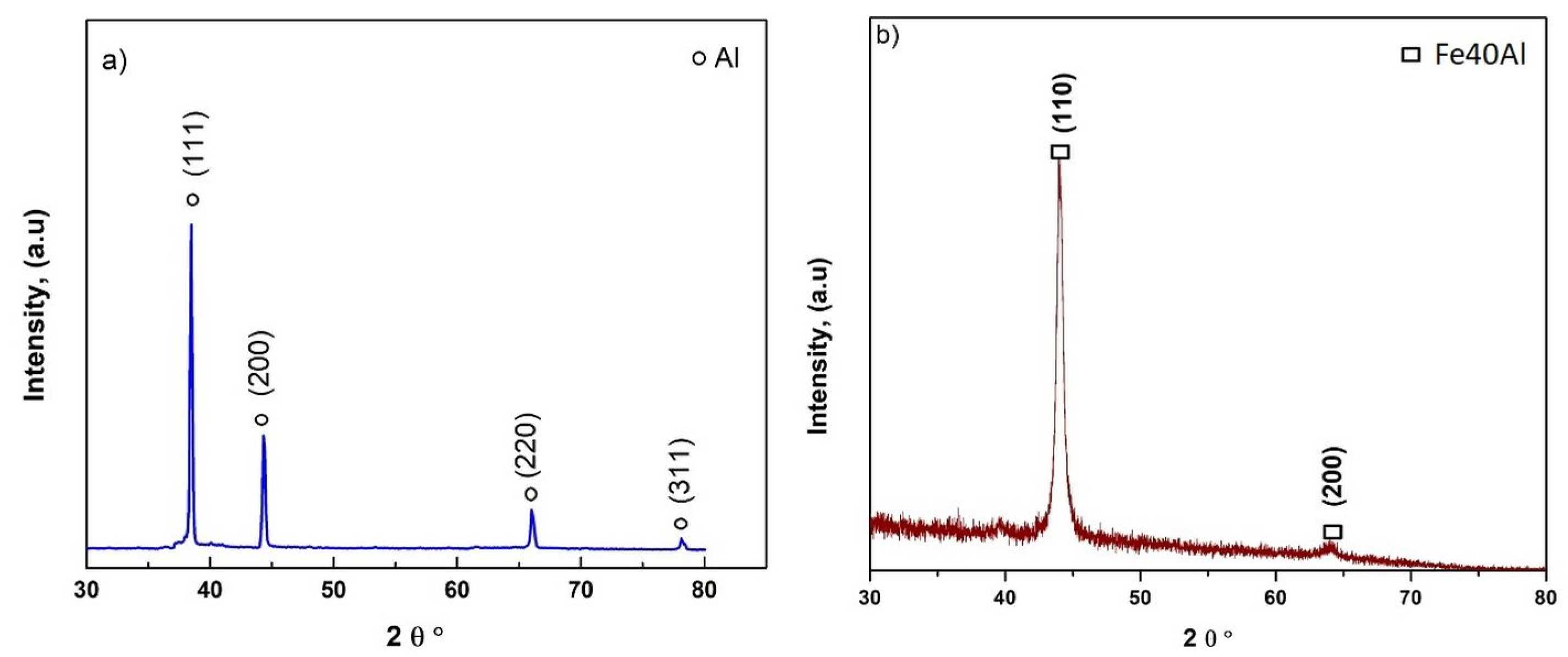
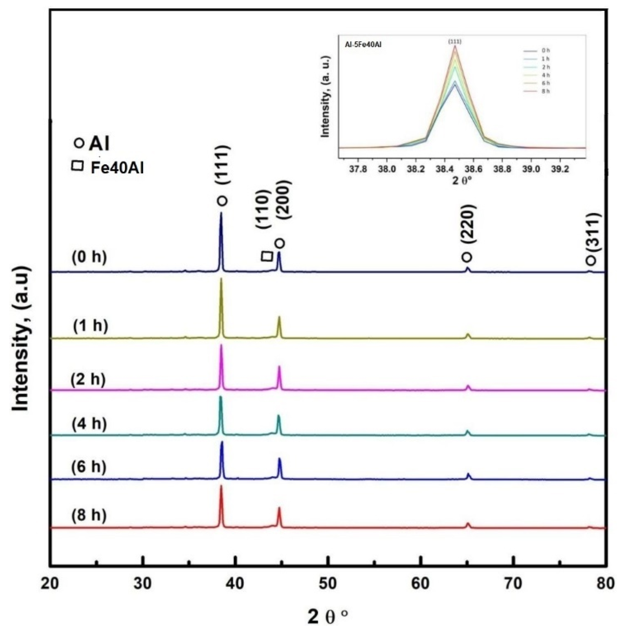
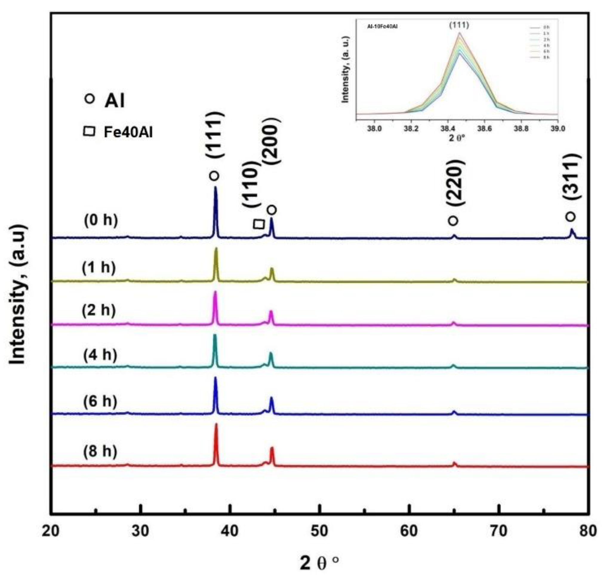
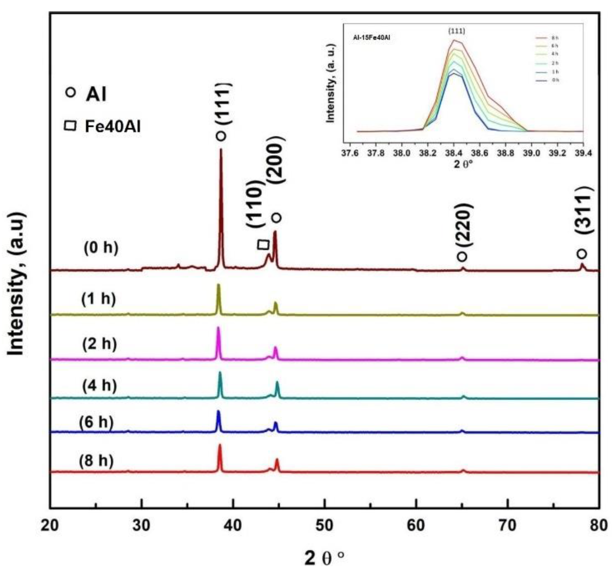
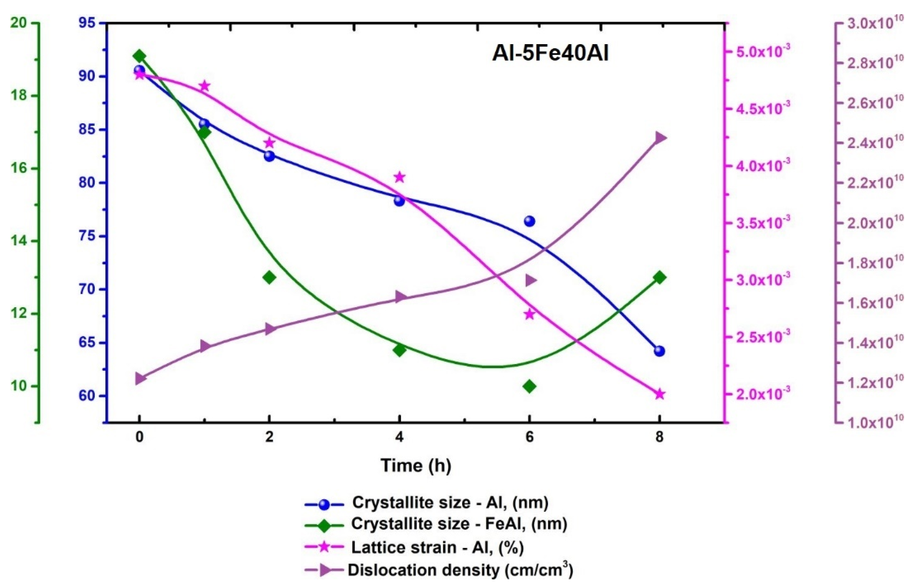
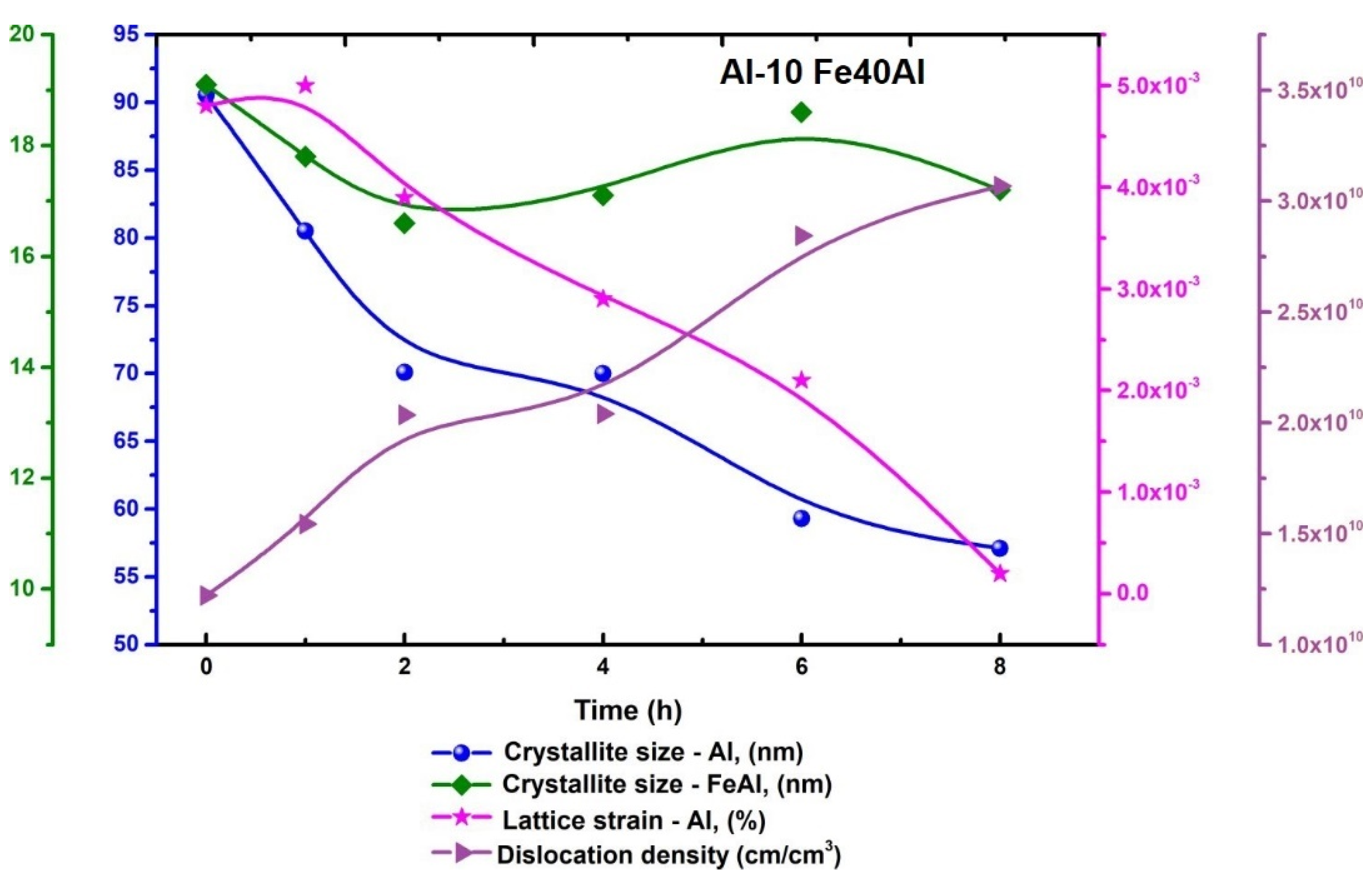
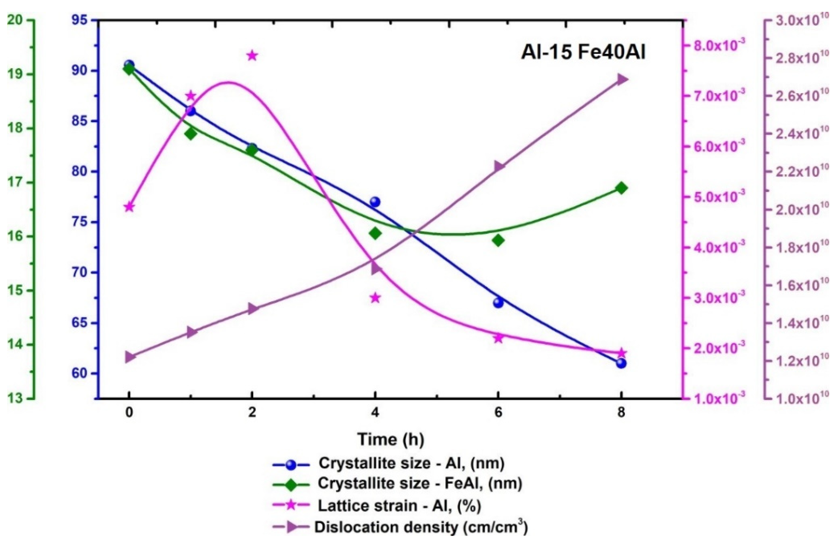
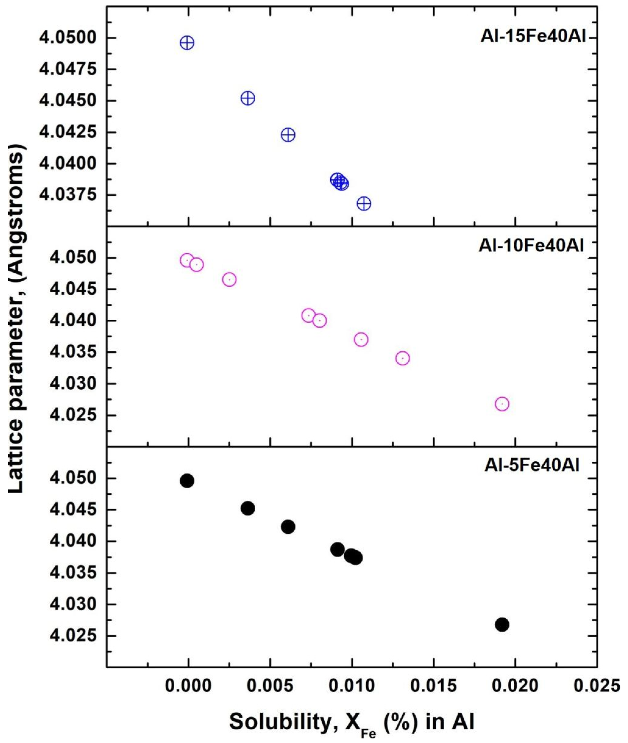
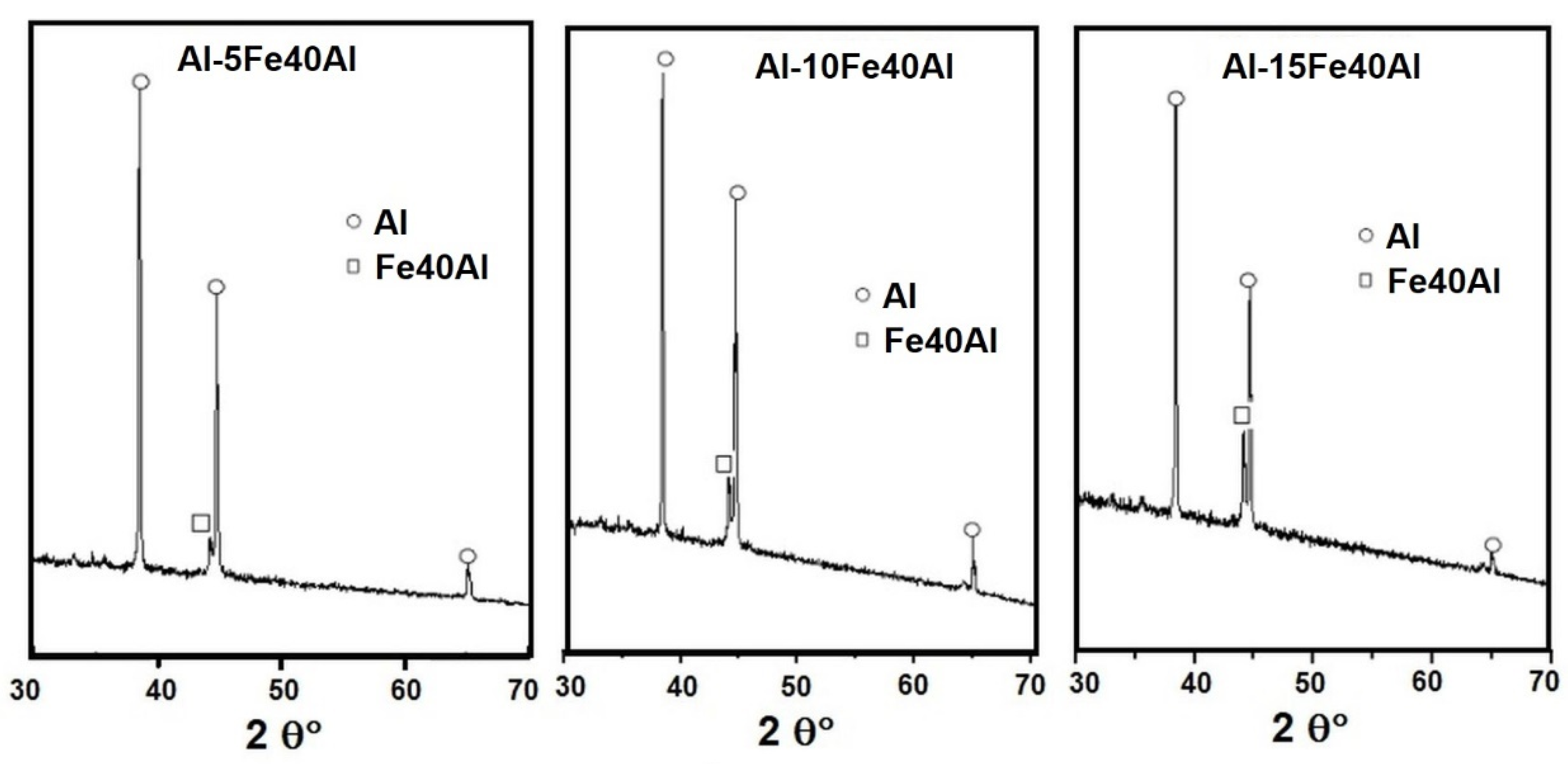
3.2. Microstructural Analysis by X-ray Diffraction

Figure 5a,b depicts the X-ray diffractograms of the pure Al and Fe40Al intermetallic phases, both in particulate powder aggregation. The X-ray diffractograms of Al exhibit the (111), (200), (220), and (311) diffraction peaks, indicating that the crystal orientations inside the powder particles were randomly distributed. In addition, Figure 5b illustrates the (110) and (200) diffraction peaks related to the intermetallic particulate phase. In this case, the presence of only two diffraction peaks could be due to a preferential crystallographic orientation since the intermetallic particulate powder was produced by a solid-state trituration and pulverization process from ingots with coarse grains.
Figure 6, Figure 7 and Figure 8 depict the X-ray diffraction patterns of the powder mixtures subjected to mechanical milling at various processing times. In accordance with the diffraction patterns, only the diffraction peaks of Al can be predominantly observed. The presence of the diffraction peaks of Fe-Al is negligible; this behavior could be related to the low content of the intermetallic phase and the possible overlap of the peaks of the intermetallic phase with those of aluminum. The highest peaks of Al pertain to the reflections produced by the (111) crystallographic planes. From 0 to 8 h of milling time, the little peak corresponding to the Fe40Al vanished progressively. This behavior could be related to a combined effect consisting of the disorder or amorphization of the Fe40Al intermetallic phase during the processing period.
There is no evidence of the presence of secondary phases that could have been produced by mechanochemical reactions among Al and Fe40Al. It can be observed that the intensity of the Fe40Al diffraction peak increased as the content of the intermetallic phase increased in the Al-xFe40Al powder mixtures. All the diffractograms show that the width of peaks at half its height belonging to the Al exhibited a trend to increase as the milling time elapsed. It is well known that this tendency is related to a decrease in the crystallite size and the generation of lattice strain [20].
Figure 9, Figure 10 and Figure 11 exhibit the dependence of the crystallite size as a function of the processing time of the powder mixtures composed of Al-5Fe40Al, Al-10Fe40Al, and Al-15 Fe40Al, respectively. In this case, the nanometric size of grains was determined from all the X-ray diffraction peaks, and a mean value of the crystallite size was calculated. The crystallite size (nm) was computed by the typical method that employs the Scherrer equation [21] by utilizing the width of the XRD diffraction peak at half its height. It is worth noticing that the trend of the decreasing crystallite size in the ball milling process has typically been reported in the literature where Al composite powders were subjected to this non-equilibrium processing technique [22,23,24,25].
Crystallite sizes were utilized to compute dislocation density. In a preliminary approach, dislocation density was considered to be at least one dislocation per crystallite. Thus, in agreement with Equation (1), dislocation density (N) becomes the inverse square of the crystallite size (Lc) [26].
N = ( L c ) 2
The variation of crystallite size for both the Al solid solution and Fe40Al intermetallic phase, along with the lattice strain, dislocation density, and the processing period of the Al-5Fe40Al powder mixture, is shown in Figure 9. This plot reveals that the nano-scaled grain size of the (alpha) Al phase displayed a tendency to decrease from about 90 nm at the onset of the process to around 65 nm at the end of mechanical milling (8 h). Concerning the Fe40Al intermetallic compound, its nano-metric grain size underwent a reduction from around 19 nm (at 0 h) to about 10 nm at 6 h; however, afterward, the powder mixture increase from 10 nm at 6 h to around 13 nm at 8 h. The lattice strain presented in Figure 9 exhibited a trend of decreasing from 1 h to 8 h of milling; however, after 8 h of processing, it displayed a trend of increasing until the end of milling. In this case, the fact that the dislocation density continuously increased from the start of the process to the end of 15 h of milling suggests that the lattice strain decreased during the first 8 h of processing because the Al phase predominantly experienced removal of vacancies, stacking failures, and punctual defects, among others.
The fact that the nano-scaled grain size of the intermetallic iron aluminide showed a decrease during the first 6 h and a subsequent increase up to 8 h of milling may be due to the dynamic recrystallization nature that it is typically observed during the hot deformation of ordered alloys. It was reported that during the deformation process within a temperature range of 600–700 °C, where <111> super-dislocations operate, dynamic recrystallization developed very slowly [27]. However, at temperatures within the interval of 750–900 °C, where <100> super-dislocations operate, dynamic recrystallization progressed rapidly [28] (Imayev et al., 1995).
The changes in the crystallite sizes for both Al and Fe40Al phases, along with the lattice strain, dislocation density, and the processing time of the Al-10Fe40Al powder mixture are shown in Figure 10. This graph indicates that the nano-scaled grain size of (alpha) Al phase displayed a decreasing trend from about (80 nm) at the beginning of the process to around (57 nm) at the end of the ball milling (8 h). Regarding the Fe40Al intermetallic phase, its crystallite size experienced a decrease from 19 nm at (0 h) to 16.5 nm at (2 h) of milling; however, after that period, the powder mixture increased from 16.5 nm at (2 h) to 18.5 nm at (6 h), and finally, decreased again after 6 h, until the nanometric grain-size reached a value of 17 nm at the end of processing. The lattice strain exhibited a decreasing trend from 1 h to 8 h of milling. In this case, the fact that the dislocation density continuously increased from the start of the process to the end of the 15 h of milling suggests that the lattice strain decreased during the first 8 h of processing because the Al phase predominantly experienced removal of vacancies, stacking failures, and punctual defects, among others.
The fact that the crystallite size of the intermetallic phase showed fluctuating behavior as a function of processing time may be due to the dynamic recrystallization character that is frequently observed in the hot deformation of ordered alloys. It could also be due to the fact that local high temperatures in the impact zone of the balls can reach up to 600 °C and the temperature also varies depending on the impact mode. Thus, it is expected that the dynamic recrystallization will be altered, considering as well that this process operates very slowly in the temperature range of 600 to 700 °C [29]; however, at high temperatures (750–900 °C), recrystallization develops rapidly [30]. This explains why the irregular variations in crystal size depend on the dynamic recrystallization processes for which the driving force is the temperature (which, in this case, varies from one point to another in the impact zones of the balls) and deformation.
The variations of nano-scaled grain sizes for both Al and Fe40Al phases, along with the lattice strain, dislocation density, and the ball milling time of the Al-15Fe40Al powder mixture are displayed in Figure 11. This plot depicts that the nano-metric grain size of the solid solution (alpha) Al showed a tendency to decrease from about (90 nm) at the beginning of the process to around (61 nm) at the end of the process (8 h). Regarding the Fe40Al intermetallic phase, its nanometric grain size decreased from around 19 nm at 0 h of milling to about 16.8 nm at the end of processing. The lattice strain exhibited a predominant decreasing trend for almost the entire processing period. Similarly, in this case, the curve of the dislocation density versus the milling time depicted a continuous rise from the beginning to the end of the non-equilibria processing; this behavior is reasonable since the increase in dislocations was generated by a plastic deformation process that took place during milling. In this way, during the deformation process, a hardening of the particles was induced by the increase in dislocation density, which, at the same time, contributed to inducing the fracture of particles. This tendency is in agreement with the continuous decrease in the size of particles as the milling time elapsed. A continuous increase in the dislocation density led to restricted dislocation motion, and afterward, led to their accumulation. When the dislocation density reaches a certain value, the crystal disintegrates into subgrains, which are separated at the beginning by low-angle grain boundaries. This process is repeated over and over until a final grain size is attained.
The crystallite size of the intermetallic compound decreased from the beginning of the process up to 6 h of milling, but after that period, the nanometric grain size decreased slightly from about 16 nm to 17 nm until the end of the mechanical milling. This behavior could be explained in terms of the complexity of the recovery and recrystallization process that develops in ordered alloys during milling. The intricate kinetics of these processes are related to the following observations: the drastic reduction in grain motion in ordered alloys severely delays recrystallization, a temperature interval is present where recrystallization does not develop, and the pre-recrystallization behavior relies on the annealing temperature and alloy composition.
Figure 12 shows Vegard’s law plot calculated from the reticular constants obtained using the experimental results of the three Al-xFe40Al powder mixtures. This plot shows that the lattice parameter of Al or the solid solution Al-Fe varies mostly in a linear way from 0 to 8 h of ball milling. In this case, the physical origin of the deviations of the lattice constants from Vegard’s law could be mainly due to the large size mismatch between Al and Fe [31]. Figure 12 exhibits that a solid solubility of about 0.02% was reached in the case of Al-5Fe40Al and Al-10Fe40Al powder mixtures. However, the Al-15Fe40Al powder mixture exhibited a solid solubility of about 0.012%.

3.3. Microstructural Characterization by Microscopy of Consolidated Specimens

Figure 13 shows optical micrographs corresponding to the Al-5Fe40Al, Al-10Fe40Al, and Al-15Fe40Al consolidated samples. Figure 13a,b and Figure 14c show bright phases (Fe40Al) uniformly distributed in a dark grey matrix (Al). The bright intermetallic phases presented an irregular morphology. The mean particle size corresponding to the intermetallic phase in Al-5Fe40Al composite was 9.2 microns with a standard deviation of ±3.6. Regarding the mean particle size of the Fe40Al particles in the Al-10Fe40Al composite, the computed value was 9.5 microns with a standard deviation of ±4.8. Concerning the mean particle size of the reinforcement Fe40Al particles in the consolidated composite Al-15Fe40Al, the calculation procedure gave a value of 10.8 microns with a standard deviation of ±4.1. This uniform size of intermetallic particles indicates that during milling, there was not a significant decrease in its size; however, the size of the Al particles exhibited a higher decrease percentage. Figure 13d–f exhibits the distribution of the precipitate size of the Fe40Al intermetallic particles. In the first composite composition, Al-5Fe40Al, most of the Fe40Al intermetallic particles are within the size interval of 4.4 to 8 μm. Concerning the composite composition of Al-10Fe40Al, most intermetallic particles are within the size interval of 8.8 to 20.8 μm.

3.4. Microstructural Characterization by X-ray Diffraction of the Consolidated Specimens

Figure 14 exhibits the X-ray diffraction profiles of Al-xFe40Al specimens after the sintering treatment. The diffraction peak corresponding to the Fe40Al intermetallic phase grew after the sintering heat treatment. In this case, the intensity of the diffraction peak of the intermetallic phase was significantly greater than those observed in the X-ray diffraction peaks of the specimens that were mechanically milled. This behavior could be related to the crystallization of the Fe40Al intermetallic phase, which was induced by the sintering process. First, the Fe40Al intermetallic phase underwent amorphization during the ball milling process, and after, the compound crystallized because of sintering. Moreover, it is worth noticing that during the sintering, the crystallite size of the aluminum increased in accordance with the following percentages: in Al-5Fe40Al—29.6%, in Al-10Fe40Al—57.3%, and in Al-15Fe40Al—31.01%.

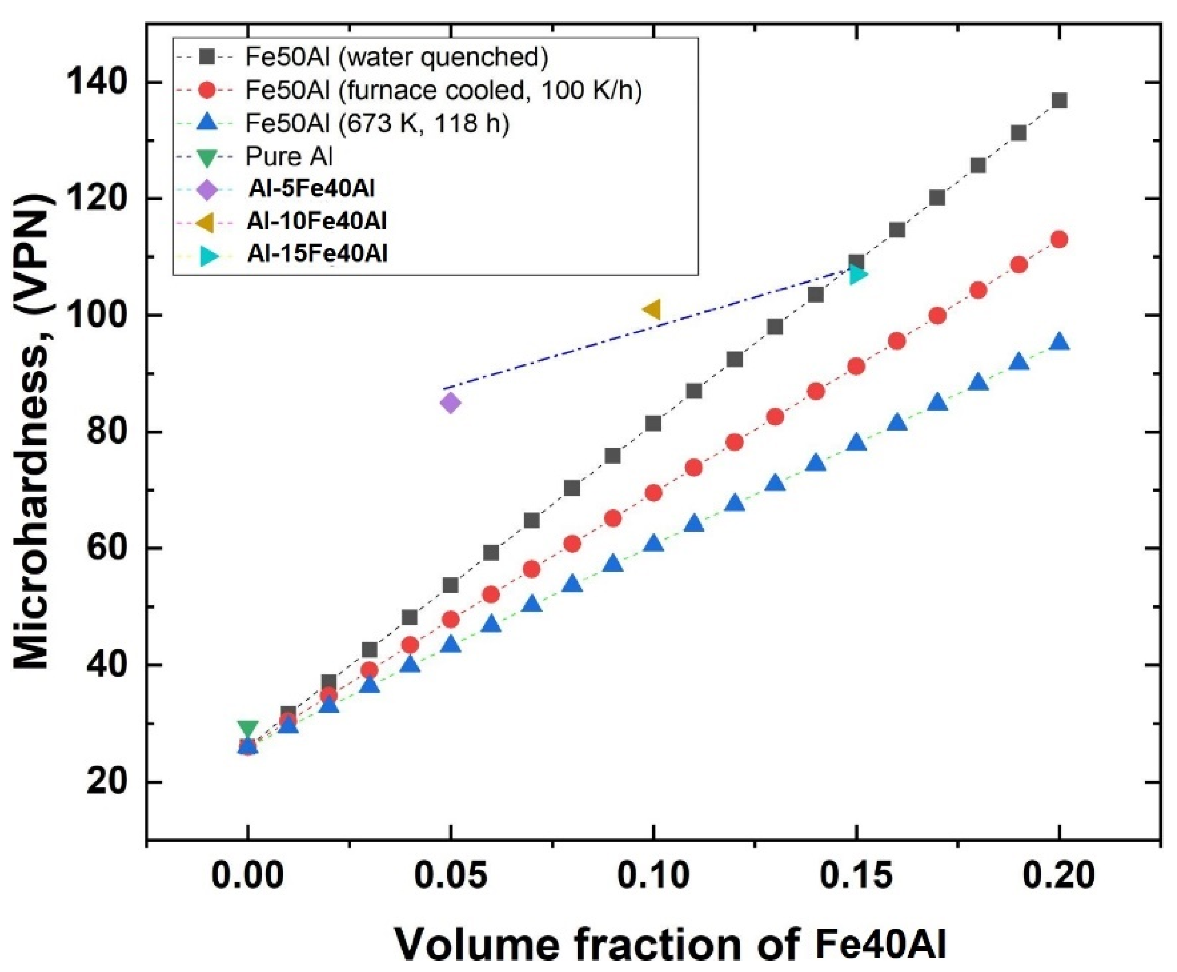
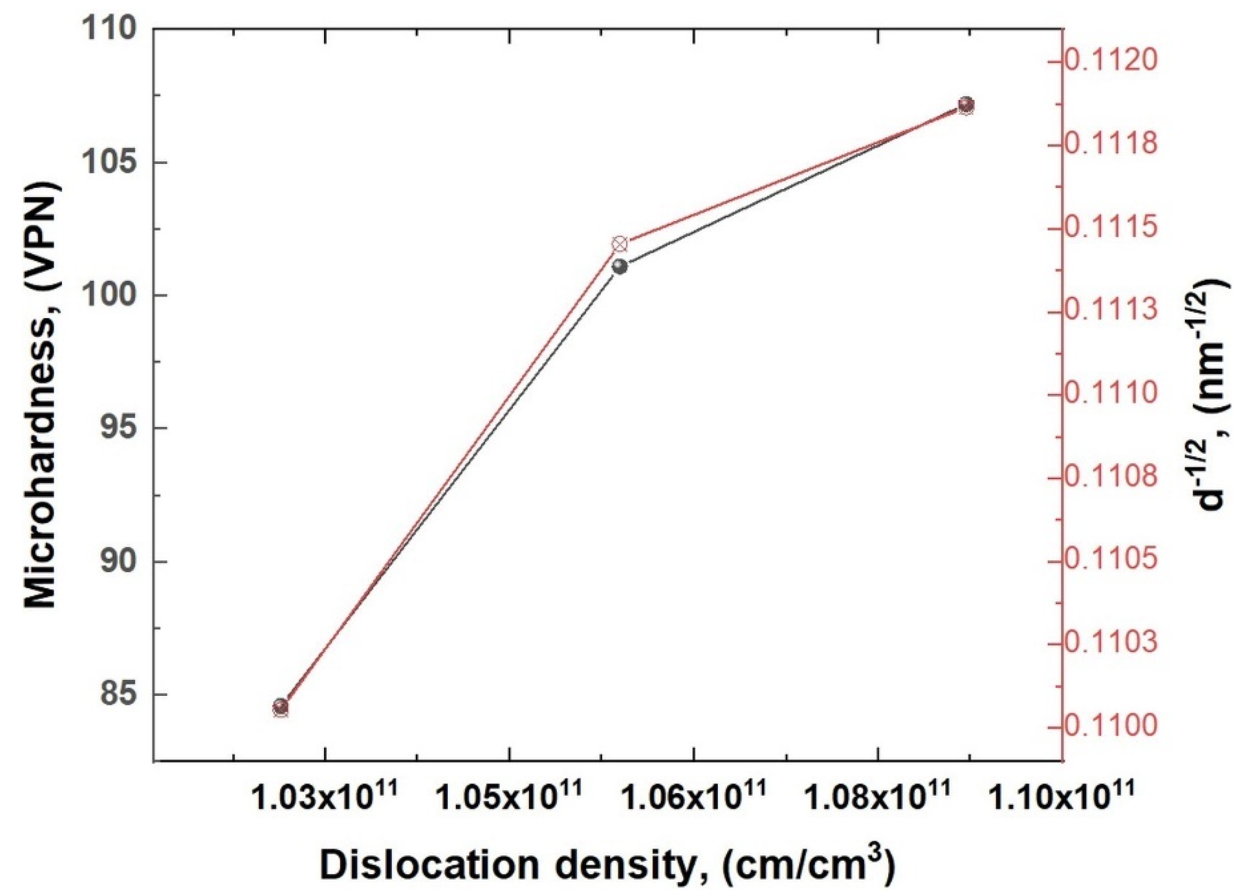
3.5. Microhardness of Sintered Samples

Figure 15 displays the three values of the hardness of the Al-5Fe40Al, Al-10Fe40Al, and Al-15Fe40Al composites determined in the present work, with values of 84.6, 101.1, and 107.2 VPN, respectively. In this case, the hardness also varied almost linearly with an increase in the volume fraction of the reinforcement phase [32]. In addition, the microhardness value of the pure Al utilized as the matrix is presented in the above-mentioned plot.
Aiming to compare the hardness values measured in the present work with a theoretical basis, a model that describes the variation of hardness as a function of the reinforcement phase concentration was developed. In this theoretical model, the hardness values of pure Al and those of the Fe50Al intermetallic compounds (under different processing conditions) were taken from the literature [33]. The composition of the Fe50Al intermetallic phase was considered since its hardness is similar to that of the Fe40Al intermetallic phase. Then, the hardness values were modeled as a function of the volume fraction of the reinforcement phase (Fe50Al), in accordance with the rule of mixtures that is represented by the following equation:
p c = f i p i = f 1 p 1 + f 2 p 2 + + f n p n
where pc is the property of compound; p1, p2, … pn are the properties of each of the constituents of composite material, and f1, f2, … fn are the volume fractions of each of the components. However, the property modeled here was hardness.
Figure 15 displays the variation of hardness modeled as a function of the volume fraction of the reinforcement phase (Fe50Al), considering, in all cases, an aluminum (Al) matrix. The three curves presented in this plot were generated by considering the hardness of the Fe50Al intermetallic compounds reported in previous works that were processed under the following parameters: water quenched, furnace cooled at 100 k/h, and annealed at 673 K for 118 h [33]. In these three curves, the hardness of the Al matrix composite changed linearly with increases in the Fe50Al reinforcement phase [32].
It was observed that the hardness values of the Al-5Fe40Al, Al-10Fe40Al, and Al-15Fe40Al measured in the present research exhibited higher values than the hardness modeled as a function of the content of the Fe50Al reinforcement phase [33], as can be observed in Figure 15. The hardening effect observed in the composite produced in the present study is due to the hardening mechanism induced by the solid solution of solute Fe in solvent Al, which promotes the formation of strain fields around solute atoms, which, in turn, interact with the stress fields of dislocations and obstruct dislocation motion. Other reasons that promoted the hardness increase in the sintered specimens were the work hardening effect induced by the plastic deformation during milling, the continuous generation of dislocations, and the interruption of dislocation motion [34].
Figure 16 shows the dependence of hardness on dislocation density. In this case, the dislocation density was estimated from the Al-5Fe40Al, Al-10Fe40Al, and Al-15Fe40Al specimens that were subjected to the ball milling process for 8 h. In this plot, a linear relationship of both variables is depicted. For this analysis, the dislocation density was considered to remain constant during sintering since the predominant material transport mechanism occurs by surface, volume, or grain boundary diffusion, or even by vaporization and re-condensation [35]. In addition, Figure 16 displays a relatively linear increase in hardness with increasing dislocation density. This behavior is reasonable since, during the mechanical milling, the particles experienced a plastic deformation. This phenomenon is associated with the hardening of crystals due to an increase in the dislocation density and the mutual interaction of dislocations. When dislocations move, they interact and change their distribution and density, thereby causing hardening [36].
The variations of microhardness as a function of the grain size for the three composites, Al-5Fe40Al, Al-10Fe40Al, and Al-15Fe40Al, are presented in Figure 16. In this plot, the microhardness values are related to the inverse square root of the grain size by a common Hall–Petch linear relationship. This correlation between the grain size and hardness was demonstrated by a variety of previous research studies on unreinforced alloys of Al [37,38,39].

4. Conclusions

During the stage of the mechanical milling process, the particle size of the initial powder mixtures of compositions Al-5Fe40Al, Al-10Fe40Al, and Al-15Fe40Al exhibited a predominant decreasing trend as the milling time progressed from the beginning to the end of the non-equilibria processing. For the case of the Al-5Fe40Al powder mixture, its particle size decreased from 4.7 µm at 0 h to 1.6 µm at 4 h, but after increased again up to 2.25 µm at 8 h. Regarding the Al-10Fe40Al powder mixture, its particle size decreased from 4.1 µm at 0 h to 0.9 µm at 8 h of processing. Finally, concerning the Al-15Fe40Al powder mixture, its particle size decreased from 4.2 µm at 0 h to 2.8 µm at 8 h of ball milling.
The X-ray diffraction analyses revealed that the crystallite size of the Al decreased during all of the processing periods and for all three compositions, and the crystallite size of the Fe40Al intermetallic phase tended to decrease during the first 4 h of milling. During the mechanical milling, there was no evidence of the formation of additional phases that could be formed by mechanochemical synthesis.
The crystallite size of the (α) Al phase in the Al-5Fe40Al powder mixture exhibited a decreasing trend from 90 nm at the onset of the process to 65 nm at the end of mechanical milling (8 h). Regarding the Al-10Fe40Al powder mixture, the nanometric grain size of the (α) Al phase displayed a decreasing trend from 90 nm at 0 h to 57.5 nm at 8 h. Finally, concerning the Al-15Fe40Al powder mixture, the nano-scaled grain size of the (α) Al phase showed a propensity to decrease from 90 nm at (0 h) to 61 nm at (8 h).
During ball milling, the Fe dissolved progressively in the Al matrix. In this case, the lattice parameter of the Al followed Vegard’s Law since the reticular constant changed almost in a linear way with the percentage of the Fe dissolved in the Al matrix. Consolidation of the Al-xFe40Al powder mixtures produced solid and rigid pieces with low volume fractions of porosity, and optical micrographs revealed a uniform distribution of the Fe40Al intermetallic phase on the Al matrix. Moreover, XRD analyses of the consolidated specimens indicated that there was no evidence of the formation of secondary phases during the sintering process. During the mechanical milling, the intermetallic phase experienced amorphization; however, during sintering, the amorphous phase recrystallized again, as revealed by the definition of the diffraction peaks of the Fe40Al phase in the XRD patterns.
The addition of Fe40Al to the Al matrix effectively induced a hardening effect. This may have been due to the mechanisms of solid solution hardening, plastic deformation, and precipitation. Likewise, the observed hardening can be modeled in terms of the rule of mixtures as a fundamental mathematical expression of the properties of composite materials.
Microhardness (Vickers) of the Al-XFe40Al composites exhibited an increasing trend from 84 VPN with 5 vol. % of Fe40Al reinforcement up to 107 VPN when Fe40Al reinforcement was added in 15 vol. %.
The graph, representing the microhardness as a function of dislocations density and grain size, indicates that the hardness increased almost linearly with the increasing dislocations density and decreasing grain size.

Author Contributions

Conceptualization, R.A.R.D., A.M.O. and S.R.G.S.; methodology, R.A.R.D., S.R.G.S. and A.M.O.; validation, R.A.R.D.; formal analysis, J.P.C. and J.L.R.B.; investigation, R.A.R.D., J.P.C., S.R.G.S., H.C.M. and J.I.B.F.; writing—original draft preparation, R.A.R.D. and J.L.R.B.; writing—review and editing, R.A.R.D., J.L.R.B. and J.P.C.; supervision, C.A.G.R., H.C.M., J.I.B.F. and V.R.V.; project administration, R.A.R.D., C.A.G.R., V.R.V. and A.M.O. All authors have read and agreed to the published version of the manuscript.

Funding

This research received no external funding.

Institutional Review Board Statement

Not applicable.

Informed Consent Statement

Not applicable.

Acknowledgments

The authors thank our affiliated institutions for the facilities granted for carrying out this research work. The authors also acknowledge Eng. Jaime Agustin Ramírez Ibarra for his technical support.

Conflicts of Interest

The authors declare no conflict of interest.

References

  1. Kainer, K.U. Basics of Metal Matrix Composites. In Metal Matrix Composites; John Wiley & Sons, Ltd.: Hoboken, NJ, USA, 2006; pp. 1–54. ISBN 978-3-527-60811-9. [Google Scholar]
  2. Köhler, E.; Niehues, J. Aluminum-matrix Composite Materials in Combustion Engines. In Metal Matrix Composites; John Wiley & Sons, Ltd.: Hoboken, NJ, USA, 2006; pp. 95–109. ISBN 978-3-527-60811-9. [Google Scholar]
  3. Weinert, K.; Buschka, M.; Lange, M. Machining Technology Aspects of Al-MMC. In Metal Matrix Composites; John Wiley & Sons, Ltd.: Hoboken, NJ, USA, 2006; pp. 147–172. ISBN 978-3-527-60811-9. [Google Scholar]
  4. Tan, M.J.; Zhang, X. Powder Metal Matrix Composites: Selection and Processing. Mater. Sci. Eng. 1998, 244, 80–85. [Google Scholar] [CrossRef]
  5. Fogagnolo, J.B.; Velasco, F.; Robert, M.H.; Torralba, J.M. Effect of Mechanical Alloying on the Morphology, Microstructure and Properties of Aluminium Matrix Composite Powders. Mater. Sci. Eng. 2003, 342, 131–143. [Google Scholar] [CrossRef]
  6. Ozdemir, I.; Ahrens, S.; Mücklich, S.; Wielage, B. Nanocrystalline Al–Al2O3p and SiCp Composites Produced by High-Energy Ball Milling. J. Mater. Process. Tech. 2008, 205, 111–118. [Google Scholar] [CrossRef]
  7. Lu, L.; Lai, M.O.; Zhang, S. Preparation of Al-Based Composite Using Mechanical Alloying. Key Eng. Mat. 1995, 104–107, 111–124. [Google Scholar] [CrossRef]
  8. Scudino, S.; Liu, G.; Sakaliyska, M.; Surreddi, K.B.; Eckert, J. Powder Metallurgy of Al-Based Metal Matrix Composites Reinforced with β-Al3Mg2 Intermetallic Particles: Analysis and Modeling of Mechanical Properties. Acta. Mater. 2009, 57, 4529–4538. [Google Scholar] [CrossRef]
  9. Hashim, J. The Production of Metal Matrix Composites Using the Stir Casting Technique. Ph.D. Thesis, Dublin City University, Dublin, Ireland, 1999. [Google Scholar]
  10. George, E.P.; Yamaguchi, M.; Kumar, K.S.; Liu, C.T. Ordered Intermetallics. Annu. Rev. Mater. Sci. 1994, 24, 409–451. [Google Scholar] [CrossRef]
  11. Mitra, R.; Wanhill, R.J.H. Structural Intermetallics. In Aerospace Materials and Material Technologies; Volume 1: Aerospace Materials; Prasad, N.E., Wanhill, R.J.H., Eds.; Springer: Singapore, 2017; pp. 229–245. ISBN 978-981-10-2134-3. [Google Scholar]
  12. Palm, M.; Stein, F.; Dehm, G. Iron Aluminides. Annu. Rev. Mater. Res. 2019, 49, 297–326. [Google Scholar] [CrossRef]
  13. Chaubey, A.K.; Scudino, S.; Mukhopadhyay, N.K.; Khoshkhoo, M.S.; Mishra, B.K.; Eckert, J. Effect of Particle Dispersion on the Mechanical Behavior of Al-Based Metal Matrix Composites Reinforced with Nanocrystalline Al–Ca Intermetallics. J. Alloys Compd. 2012, 536, S134–S137. [Google Scholar] [CrossRef]
  14. Varin, R.A. Design of a Low-Melting Point Metal Matrix Composite Reinforced with Intermetallic Ribbons/Design Eines Niedrig-Schmelzenden Metall-Matrix-Verbundwerkstoffes Mit Verstärkenden Intermetallischen Bändern. Int. J. Mater. Res. 1990, 81, 373–379. [Google Scholar] [CrossRef]
  15. Pour, H.A.; Lieblich, M.; López, A.J.; Rams, J.; Salehi, M.T.; Shabestari, S.G. Assessment of Tensile Behaviour of an Al–Mg Alloy Composite Reinforced with NiAl and Oxidized NiAl Powder Particles Helped by Nanoindentation. Compos. Part A Appl. Sci. Manuf. 2007, 38, 2536–2540. [Google Scholar] [CrossRef] [Green Version]
  16. Muñoz-Morris, M.A.; Rexach, J.I.; Lieblich, M. Comparative Study of Al-TiAl Composites with Different Intermetallic Volume Fractions and Particle Sizes. Intermetallics 2005, 13, 141–149. [Google Scholar] [CrossRef] [Green Version]
  17. Da Costa, C.E.; Velasco, F.; Torralba, J.M. Mechanical, Intergranular Corrosion, and Wear Behavior of Aluminum-Matrix Composite Materials Reinforced with Nickel Aluminides. Metall. Mater. Trans. A 2002, 33, 3541–3553. [Google Scholar] [CrossRef]
  18. Wolf, B.; Bambauer, K.O.; Paufler, P. On the Temperature Dependence of the Hardness of Quasicrystals. Mater. Sci. Eng. 2001, 298, 284–295. [Google Scholar] [CrossRef]
  19. Suryanarayana, C. Mater Sci Forum: A Novel Technique to Synthesize Advanced Materials. Research 2019, 2019, 1–17. [Google Scholar] [CrossRef] [Green Version]
  20. Ahmad, Z.; Abu, M.; Rahman, M.; Ain, M.F.; Ahmadipour, M. Assessment of Crystallite Size and Strain of CaCu3Ti4O12 Prepared via Conventional Solid-State Reaction. Micro. Nano Lett. 2016, 11, 147–150. [Google Scholar] [CrossRef]
  21. Cherepanov, P. High Intensity Ultrasound Processing of AlNi (50 Wt.% Ni) Particles for Electrocatalytic Water Splitting. Ph.D. Thesis, Bayreuth University, Bayreuth, Germany, 2015. [Google Scholar]
  22. Erturun, V.; Sahin, O. Investigation of Microstructural Evolution in Ball-Milling of SiC Reinforced Aluminum Matrix Composites. Powder Metall. Met. Ceram. 2019, 57, 687–696. [Google Scholar] [CrossRef]
  23. Travessa, D.N.; Silva, M.J.; Cardoso, K.R. Niobium Carbide-Reinforced al Matrix Composites Produced by High-Energy Ball Milling. Metall. Mater. Trans. A 2017, 48, 1754. [Google Scholar] [CrossRef]
  24. Tamizi Junqani, M.; Madaah Hosseini, H.R.; Azarniya, A. Comprehensive Structural and Mechanical Characterization of In-Situ Al–Al3Ti Nanocomposite Modified by Heat Treatment. Mater. Sci. Eng. 2020, 785, 139351. [Google Scholar] [CrossRef]
  25. Tomiczek, B.; Pawlyta, M.; Adamiak, M.; Dobrzański, L.A. Effect of milling time on microstructure of AA6061 composites fabricated via mechanical alloying. Arch. Metall. Mater. 2015, 60, 789–793. [Google Scholar] [CrossRef]
  26. Raghu, T.; Sundaresan, R.; Ramakrishnan, P.; Mohan, T.R. Synthesis of Nanocrystalline Copper–Tungsten Alloys by Mechanical Alloying. Mater. Sci. Eng. 2001, 304, 438–441. [Google Scholar] [CrossRef]
  27. Baker, I.; Munroe, P.R. Mechanical Properties of Fe40Al. Int. Mater. Rev. 1997, 42, 181–205. [Google Scholar] [CrossRef]
  28. Imayev, R.; Evangelista, E.; Tassa, O.; Stobrawa, J. Relationship between Mechanism of Deformation and Development of Dynamic Recrystallization in Fe40Al Intermetallic. Mater. Sci. Eng. 1995, 202, 128–133. [Google Scholar] [CrossRef]
  29. Zhan, Z.; He, Y.; Wang, D.; Gao, W. Low-Temperature Processing of Fe–Al Intermetallic Coatings Assisted by Ball Milling. Intermetallics 2006, 14, 75–81. [Google Scholar] [CrossRef]
  30. Siegel, R.W. Nanophase materials: Synthesis, structure, and properties. In Physics of New Materials; Springer: Heidelberg/Berlin, Germany, 1994; pp. 65–105. [Google Scholar] [CrossRef]
  31. Magomedov, M.N. On the Deviation from the Vegard’s Law for the Solid Solutions. Solid State Commun. 2020, 322, 114060. [Google Scholar] [CrossRef]
  32. Kaczmar, J.W.; Pietrzak, K.; Włosiński, W. The Production and Application of Metal Matrix Composite Materials. J. Mater. Process. Tech. 2000, 106, 58–67. [Google Scholar] [CrossRef]
  33. Nagpal, P.; Baker, I. Effect of cooling rate on hardness of FeAl and NiAl. Met. Trans. A 1990, 21, 2281–2282. [Google Scholar] [CrossRef]
  34. Suryanarayana, C. Mechanical Alloying and Milling. Prog. Mater. Sci. 2001, 46, 1–184. [Google Scholar] [CrossRef]
  35. Thümmler, F.; Oberacker, R. An Introduction to Powder Metallurgy. Book/The Institute of Materials; Institute of Materials: London, UK, 1993; ISBN 978-0-901716-26-2. [Google Scholar]
  36. Hull, D.; Bacon, J.D. Introduction to Dislocations, 5th ed.Butterworth-Heinemann: Oxford, UK, 2011; pp. 1–253. [Google Scholar]
  37. Rajinikanth, V.; Venkateswarlu, K.; Sen, M.K.; Das, M.; Alhajeri, S.N.; Langdon, T.G. Influence of Scandium on an Al–2% Si Alloy Processed by High-Pressure Torsion. Mater. Sci. Eng. A 2011, 528, 1702–1706. [Google Scholar] [CrossRef]
  38. Xu, C.; Horita, Z.; Langdon, T.G. The Evolution of Homogeneity in an Aluminum Alloy Processed Using High-Pressure Torsion. Acta Mater. 2008, 56, 5168–5176. [Google Scholar] [CrossRef]
  39. Loucif, A.; Figueiredo, R.B.; Baudin, T.; Brisset, F.; Langdon, T.G. Microstructural Evolution in an Al-6061 Alloy Pro-cessed by High-Pressure Torsion. Mater. Sci. Eng. A 2010, 527, 4864–4869. [Google Scholar] [CrossRef]
Figure 1. The processing route developed in the present work, involving melting and casting along with some powder metallurgy techniques of powder.
Applsci 11 08877 g001
Figure 2. Scanning electron micrograph of (a) Al powder particles and (b) Fe40Al intermetallic powder particles. Particle size distributions of (c) Al and (d) Fe40Al.
Applsci 11 08877 g002
Figure 3. Microstructural evolution of the Al-5Fe40Al powder mixture composition as a function of milling time: (a) 0 h, (b) 2 h, (c) 4 h, (d) 8 h. Al-10Fe40Al: (e) 0 h, (f) 2 h, (g) 4 h, (h) 5 h. Al-15Fe40Al: (i) 0 h, (j) 2 h, (k) 4 h, (l) 6 h.
Applsci 11 08877 g003
Figure 4. Variations of the mean particle size with the processing time of all powder mixtures (Al-5Fe40Al, Al-10Fe40Al, and Al-15Fe40Al) as a function of the ball milling period.
Applsci 11 08877 g004
Figure 5. X-ray diffraction profiles of (a) pure Al and (b) Fe40Al intermetallic phase.
Applsci 11 08877 g005
Figure 6. X-ray diffraction profiles of the powder mixture of Al-5Fe40Al at different processing times.
Applsci 11 08877 g006
Figure 7. X-ray diffraction profiles of the powder mixture of Al-10Fe40Al at different processing times.
Applsci 11 08877 g007
Figure 8. X-ray diffraction profiles of the powder mixture of Al-15Fe40Al at different processing times.
Applsci 11 08877 g008
Figure 9. Variation of crystallite size of Al and Fe40Al, lattice strain (Al), and dislocation density (Al) as a function of processing time for Al-5Fe40Al powder mixture.
Applsci 11 08877 g009
Figure 10. Variations of the crystallite sizes of Al and Fe40Al, lattice strain (Al), and dislocation density (Al) as a function of processing time for the Al-10Fe40Al powder mixture.
Applsci 11 08877 g010
Figure 11. Variations of crystallite sizes of Al and Fe40Al, lattice strains (Al), and dislocation density (Al) as a function of processing time for Al-15Fe40Al powder mixture.
Applsci 11 08877 g011
Figure 12. Variations of the sizes of lattice parameters of Al in Al-5Fe40Al, Al-10Fe40Al, and Al-15Fe40Al (vol. %) powder mixtures as a function of the milling period.
Applsci 11 08877 g012
Figure 13. Optical micrographs of consolidated specimens, (a) Al-5Fe40Al, (b) Al-10Fe40Al, and (c) Al-15Fe40Al. Particle size distribution: (d) Al-5Fe40Al, (e) Al-10Fe40Al, and (f) Al-15Fe40Al.
Applsci 11 08877 g013
Figure 14. X-ray diffraction spectra of the sintered Al-5Fe40Al, Al-10Fe40Al, and Al-15Fe40Al specimens.
Applsci 11 08877 g014
Figure 15. Vickers microhardness of composite materials Al-5Fe40Al, Al-10Fe40Al, and Al-15Fe40Al compared with the predicted values of hardness of various composites reinforced with Fe50Al intermetallics under different processing conditions.
Applsci 11 08877 g015
Figure 16. Variation of the Vickers microhardness with dislocation density and the inverse square root of the grain size, illustrating a typical Hall–Petch linear relationship.
Applsci 11 08877 g016
Publisher’s Note: MDPI stays neutral with regard to jurisdictional claims in published maps and institutional affiliations.

