1. Introduction
A metasurface (MS) is a 2D metamaterial that has electromagnetic properties that do not exist in nature. In the last two decades, ag reat deal of research has been conducted in the field of metamaterials and MSs, enabling fascinating electromagnetic properties that cannot be achieved with naturally occurring materials. In contrast to conventional materials, MSs provide a new way to manipulate microwave and MMW radiation based on reflection from sub-wavelength unit cell periodic arrays, which simultaneously have negative permeability and permittivity [
1,
2,
3]. The unique interaction between the unit cells and the electromagnetic radiation aids in the design of innovative components. Applications such as metasurface perfect absorbers [
4], cloaks [
5], flat parabolic mirror surfaces (FLAPSs) [
6], and polarization control [
7,
8] have been demonstrated experimentally.
In 1968, Veselago [
9] theoretically investigated the electrodynamic consequences of a medium having negative values of both
ε and
µ, and concluded that such a medium would have dramatically different propagation characteristics stemming from the sign change of the group velocity. However, these effects could not be experimentally verified since substances with
μ < 0 were not available. The split ring resonator (SRR) medium proposed by Pendry et al. [
10] provided the opportunity to make a material with negative permeability, from which a “left-handed” medium could be constructed. By combining the SRR with cut wire in an array structure, a left-handed material [
11] was created.
Reconfigurable metasurfaces (MSs) have attracted a great deal of interest in the last two decades. There are many interdisciplinary applications that have been realized by MSs [
12]. Applications such as a millimeter-wave sensitive sensor MS based on a perfect absorber for the detection and recognition of micro-poisons in drinking water [
13] and a W-band flat parabolic mirror for imaging systems and beam propagation [
6] are resonant, and thus they are limited to a narrow bandwidth around the resonant frequency. Adding tunability to each unit cell significantly expands the performance and versatility of the MS for innovative applications. Reconfigurability of the MS can be realized by PIN switches [
14], MEMS switches [
15], liquid crystal or piezoelectric materials [
16,
17], and varactor diodes [
8]. The PIN switch enables MSs with a fast switching time, high reliability, low cost, and low voltage control [
15]. Tunable components such as MEMS switches have attracted attention due to their small size and linearity; on the other hand, they have a relatively slow switching time compared to PIN switch diodes [
16]. The discrete nature of switches cannot be used in applications where a continuous phase change is required. Liquid crystal (LC) changes the dielectric coefficient of the unit cell substrate by tens of percentage points as a function of applied DC bias. LC can be used at K-band frequencies and above [
15]. LC has a slow response time compared to switches and varactors [
18] and a small dynamic range relative to the varactor. A piezoelectric crystal allows limited flexibility proportional to the change in its physical size and requires a relatively high DC bias [
17]. The varactor diodes enable a continuous and high dynamic range of capacitance, constant gamma for linear tuning, a convenient PCB assembly, and very low power consumption [
19].
However, the solutions offered in the literature suffer from a bandwidth problem. This makes the task of finding an efficient and practical solution more difficult. Previous works, extensively based on CST simulation code, were implemented and experimentally tested for reconfigurable MS reflectors at Ku-band [
20] and K-band [
7]. The experimental results of these MSs are in excellent agreement with the simulation results for the reflection property values and beam-steering abilities. Based on those experimental results, we propose a new configuration concept named the stripes method. The stripes configuration showed a better performance in gain, SLL, and bandwidth.
2. Unit Cell Design
In this study, a combination of two types of unit cell geometries arranged in the same MS reflector were designed.
Figure 1a–d shows a typical unit cell design consisting of a front side, back side, profile, and 3D view of two adjacent unit cells. This unit cell is composed of two PCB layers made by the Rogers Company, model RT/Duroid 5880 with
εr = 2.2 [
21], and three copper layers of 0.5 oz thickness. The unit cell is composed of two vertical stripes in the top layer with each electrical connected to a pad, in conjunction with a varactor diode (used in this study) by a horizontal appropriate microstrip line. The varactor diode, model MAVR–011020–1411 of Macom [
19], is used in this MS design due to its extremely low capacitance. The varactor diode is placed on the pad between the strips (see
Figure 1 in green), adding variable capacitance C
diode to the unit cell. The dynamic range of the capacitance is C
diode max = 0.216 pF to C
diode min = 0.032 pF for 0–15 V reverse bias voltage, respectively. One of the vertical stripes has the same length as the unit cell width, W (used for the DC ground), while the second strip, S
L, has a shorter length by 0.05 mm and is connected through a via to the back side of the PCB for the DC bias circuit. The middle copper layer acts as a metal ground for the unit cell, and it is separated by clearance (CD) from the via, as shown in
Figure 1d. To have a symmetrical unit cell design, a mirror unit cell was added, as seen in
Figure 1, where polarization- and propagation-instated reduction hits are perpendicular to the surface, as shown in
Figure 1a.
In this study, we propose a new concept referred to as the stripes configuration. The proposed configuration is composed of three stripes (1, 2, and 3) of two types of MS reflectors (Type A and type B) arranged side by side, as can be seen in
Figure 2. Each type has a different unit cell design as shown in
Table 1. The designed MS has three stripes with each stripe composed of four unit cell columns (
Figure 2). Each stripe has a different dielectric substrate thickness, h, yielding a smaller dynamic phase range improving the reflected gain. Stripe one and stripe three are identical stripes with a thickness of h = 0.6 mm. The thickness of stripe two, in the middle, is h = 0.75 mm. Using the 3D electromagnetic simulation software CST, three different unit cell parameters were investigated and optimized for best performance. The final dimensions are summarized in
Table 1. Two different MSs for 28 GHz were designed and investigated, based on the unit cells given in
Table 1. The first is a typical uniform MS (one stripe) based on a uniform unit cell. The second MS is composed of two types of unit cells, type A and type B, arranged in three stripes, as shown in
Figure 2.
There are three absorption-loss mechanisms in the proposed tunable MS: varactor diode losses caused by internal resistance of the diode (R
diode), dielectric losses, and ohmic losses [
8]. The dielectric losses and ohmic losses are well defined and quantified in the CST simulation. On the other hand, the varactor serial resistance R
diode is unknown, therefore experimental measurements from similar studies were used [
22,
23], taking manufacturing process imperfections into consideration. The approximate value of R
diode was found to be 4 Ω [
22,
23].
Table 2 summarizes the electrical parameters that were used in the simulations.
The proposed MS reflector was simulated using the TEM plane wave port with CST simulation software [
24]. The simulation results of the uniform unit cell, including magnitude and phase reflection as a function of frequency, are shown in
Figure 3. The simulations were repeated for three capacitance values: C
diode min = 0.032 pF (red), C
diode max = 0.216 pF (green), and C
diode res (28 GHz). This provided a dynamic reflection phase range of 311°, marked by a continuous black crosser, as shown in
Figure 3a. The magnitude of the reflected beam for capacitance is shown in
Figure 3b. The maximum loss value for C
diode res (28 GHz) = 0.0815 pF was 5.5 dB, marked by a continuous black crosser, as shown in
Figure 3b. The via was used for the DC bias for the varactor diode. The standard via diameter for manufacturing is 0.25 mm–0.30 mm, which had no effect on the MS’s performance.
Figure 3c describes the influence of the via diameter on the resonance frequency and the absorption, where no significant influence was found.
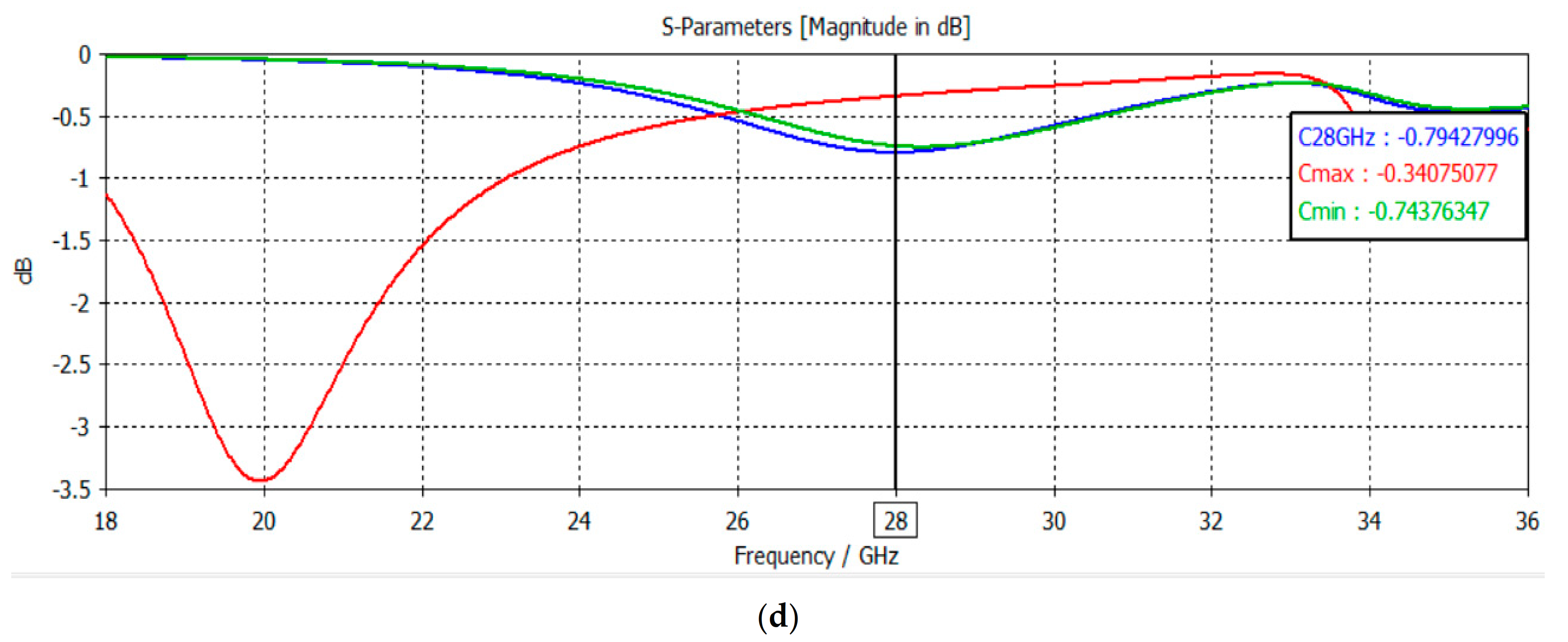
The simulation results of type A and type B unit cell phase reflection and magnitude are shown in
Figure 4 as a function of frequency for three capacitance values: C
diode min = 0.032 pF (green), C
diode max = 0.216 (red) pF, and the 28 GHz resonance capacitance C
diode res. Type A provided a dynamic reflection phase range of 236° and type B provided a dynamic reflection phase range of 150°, marked by the dashed black crossers shown in
Figure 4a,c, respectively. The maximum loss value of type A C
diode res (28 GHz) = 0.05 pF was 1.6 dB, and the maximum loss value of type B C
diode res (28 GHz) = 0.04 pF was 0.8 dB, marked by continuous black crossers in
Figure 4b,d, respectively.
The resonance frequency is related to the inductance and capacitance of the unit cell. The thickness, h, of the dielectric substrate is proportional to the inductance [
25]; thus, the change of h affects the resonance frequency and the dynamic phase range of the unit cell. The motivation to design an MS based on the stripes method was to reduce the total absorption of the proposed MS compared to the uniform type (one stripe). Changing h is advantageous since it reduces the “transition effects” (or “edge effects”), yielding a better beam-steering performance. Any differences between two adjacent stripes would disturb the periodicity of the unit cells of the whole MS, causing transition effects or edge effects, degrading the reflected beam. The advantage of changing h (the dielectric substrate thickness) eliminates this problem. In this realization, the incident wave “sees” the same geometry but with a different phase reflection, significantly decreasing the transition effects.
3. Metasurface Simulation Results
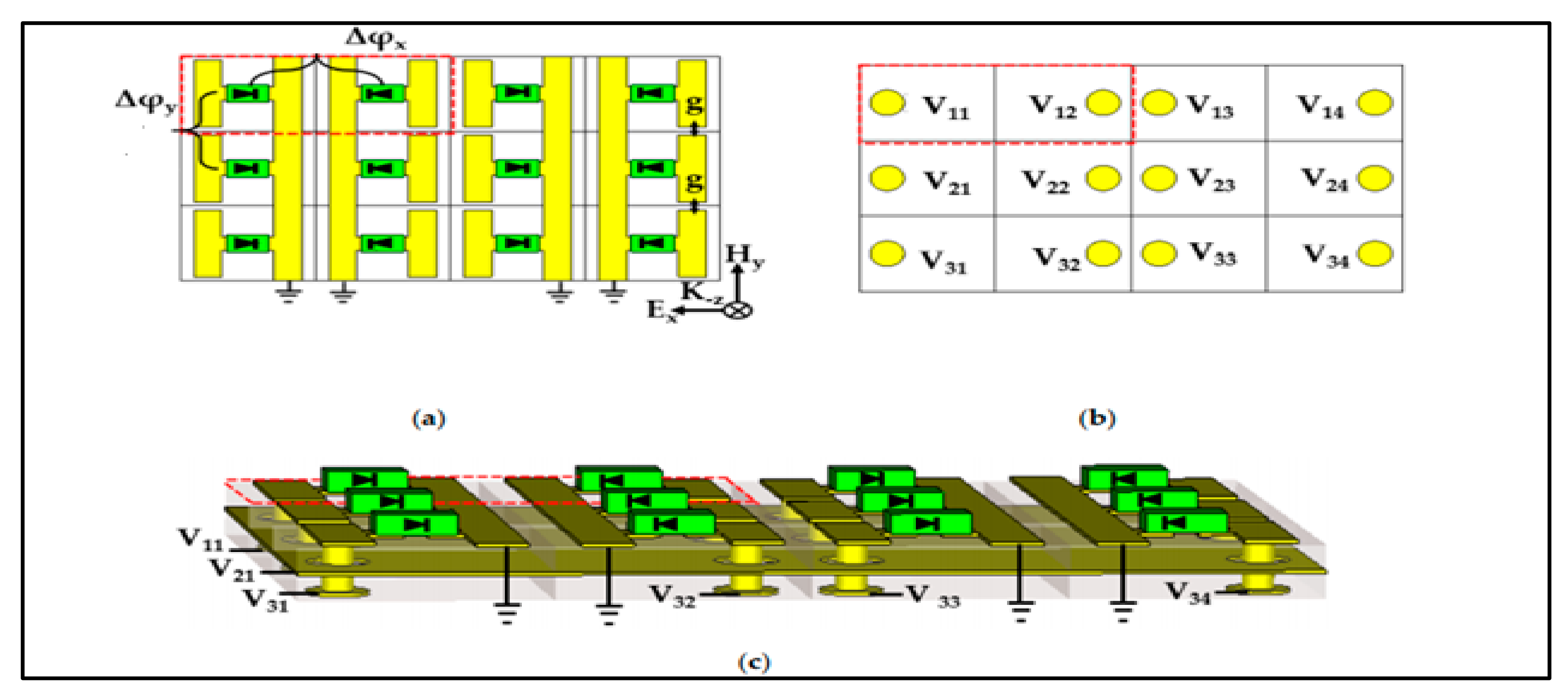
The MS reflector structure, including the DC bias circuit, is shown in
Figure 5. The MS structure and the simplicity of DC biasing reduces the complexity and the absorption of the unit cell (
Figure 3 and
Figure 4). The via and the clearance add losses to the unit cell due to the need to provide a DC bias to each varactor. The stripes of the unit cells are used as a DC ground for the varactors in one stripe column, eliminating the need for an additional via in each unit cell. The shorter strip is used for supplying the DC bias through a via, enabling each MS unit cell to be independently biased.
Figure 5 describes the MS structure including the DC bias circuit where ∆
ϕx and ∆
ϕy are the reflected phase differences between two adjacent unit cells in X and Y, respectively.
The array size was 40.8 mm × 40.8 mm with 12 rows and 16 columns of unit cells, yielding 192 independent unit cells with a separate DC voltage connection, as required. Beam steering in one dimension (the X axis, in this case) requires that every unit cell in each column is connected to the same DC voltage/basis to get the desired ∆
ϕx while ∆
ϕy= 0°. The steering angle
θ for each angle was calculated, as shown in
Table 3 using (1).
where ∆
X is the distance between the canter of two adjacent unit cells, and
λ is the operating frequency wavelength. The MS was simulated using CST code for a normal incident TEM plane wave of approximately 28 GHz. The simulation results are shown in
Figure 5. Results show the main lobe difference to the side lobe at more than 10 dB. The results can be improved by approximately 3 dB by using the optimal phase dynamic range with the stripes configuration. For the beam-steering mode, considering the dynamic phase range and MS size, the phase difference parameter ∆
ϕx is limited according to Equation (2) for type A and Equation (3) for type B.
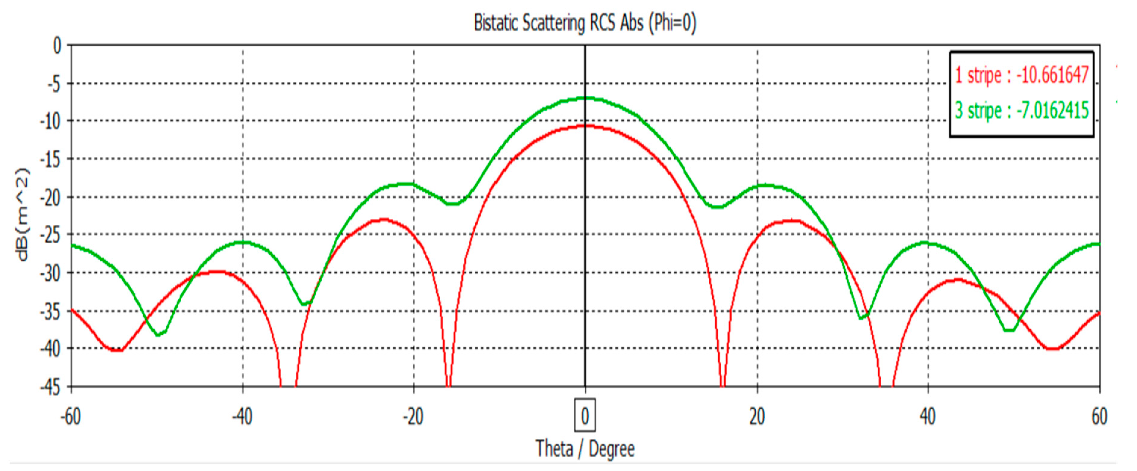
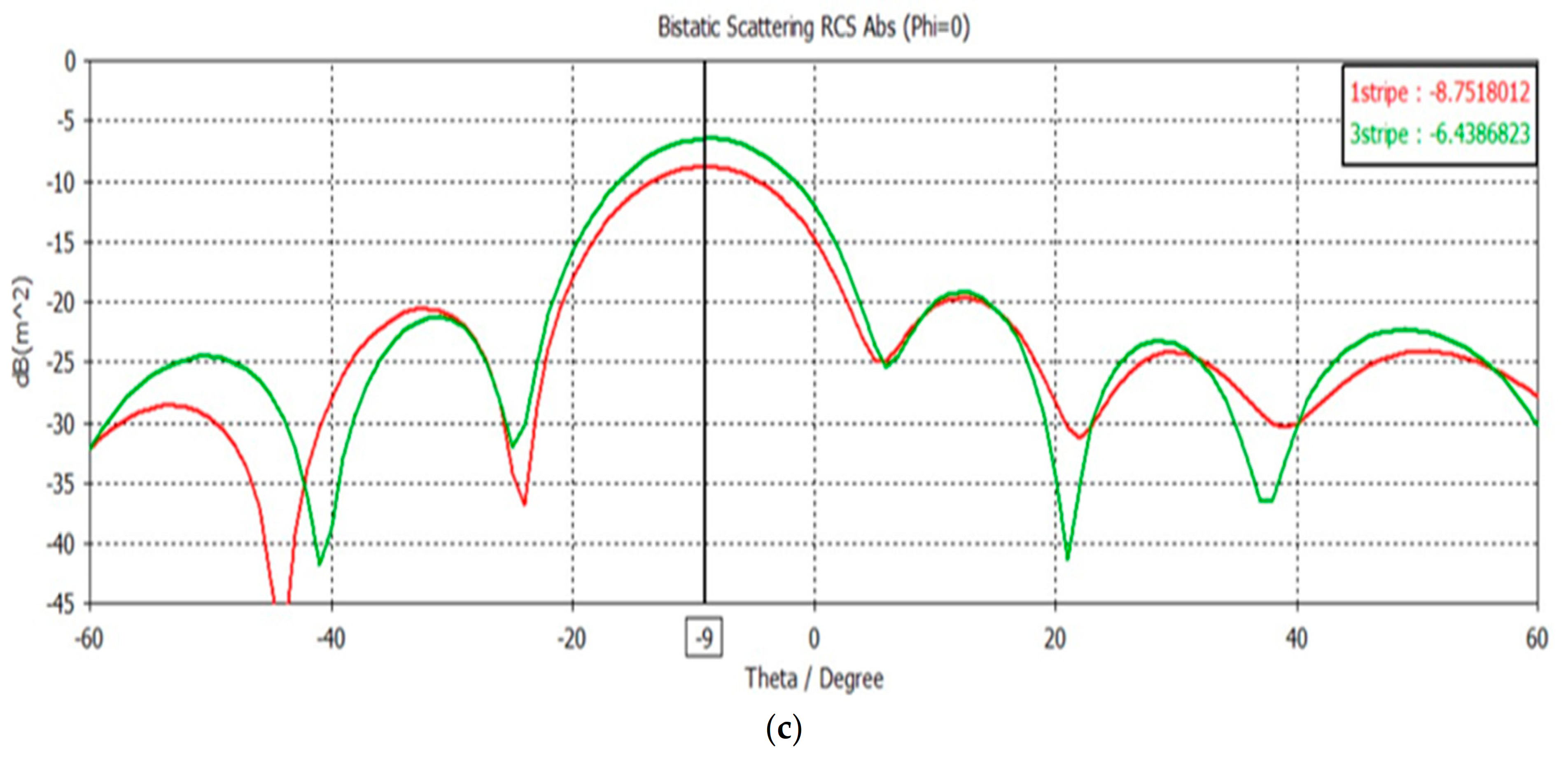
In
Figure 6a, beam steering at
θ = 0° around the resonant frequency with the highest absorption is shown. The solid red line describes the beam reflected gain of one stripe (uniform) MS and the solid green line describes the beam reflected gain for the three stripe configuration. The three-stripe gain curve showed significantly better performance compared to the gain in the one-stripe configuration (red line) by approximately 3.6 dB. Furthermore, the larger the steering angle was, the better the reflected gain of the three-stripe configuration compared to one stripe (uniform) MS.
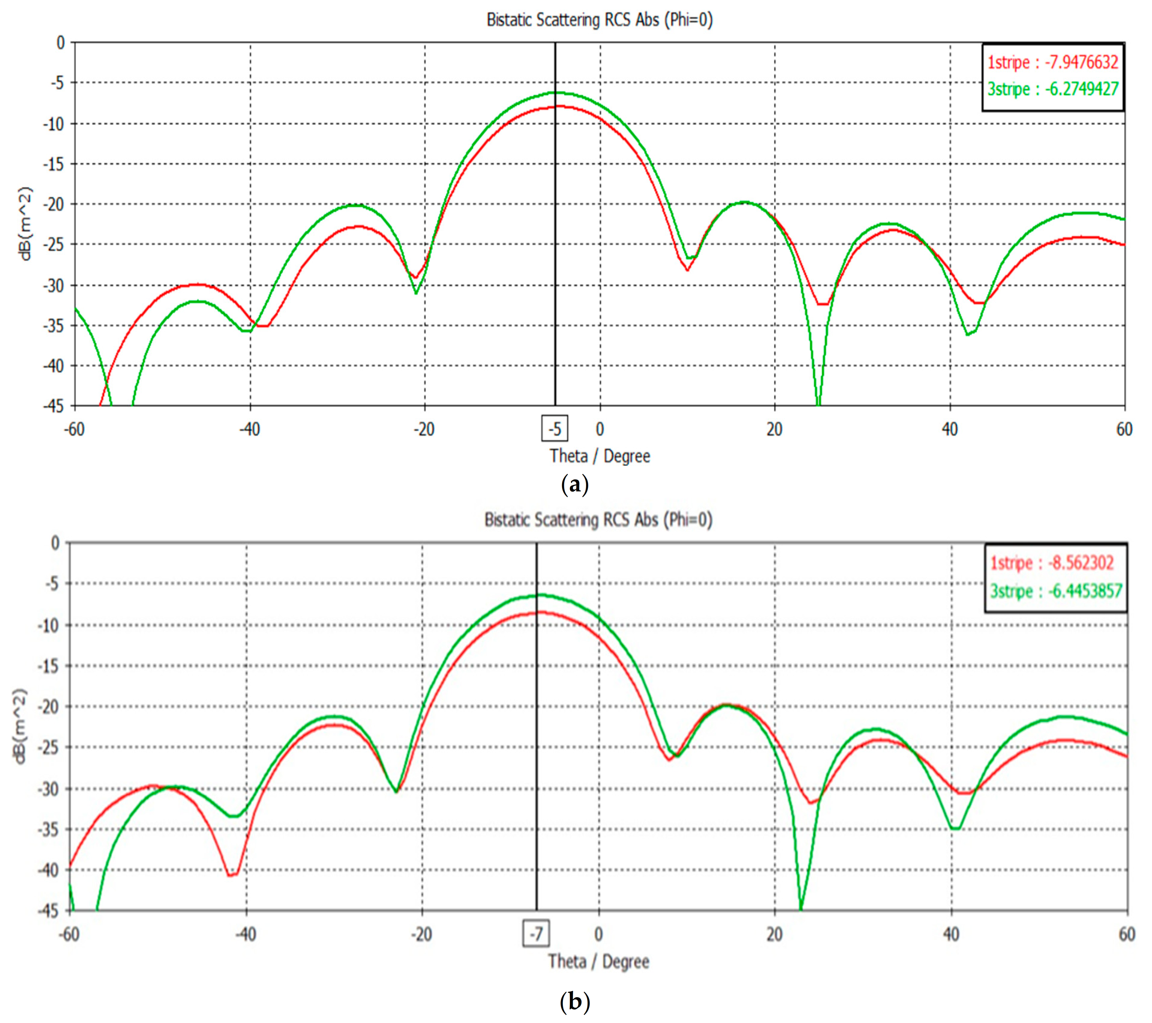
Figure 7 describes the simulation results of a typical one-stripe configuration and the simulation of a three-stripe configuration for steering angles of
θ = 5°,
θ = 7°, and
θ = 9°.
The co-polarization and cross polarization properties of the proposed three-stripe MS was investigated for the case of 9° beam steering. The simulation results show that most of the transmitted power was reflected in the co-polarization. The cross polarization was below 50 dB, referring to the co-polarization, as seen in
Figure 8.
There was a correlation between the calculation in Equation (1) for beam steering and the simulation results. The stripes configuration improved the performance of the reflected beam gain by 3 dB. A significant improvement in the reflected beam angle
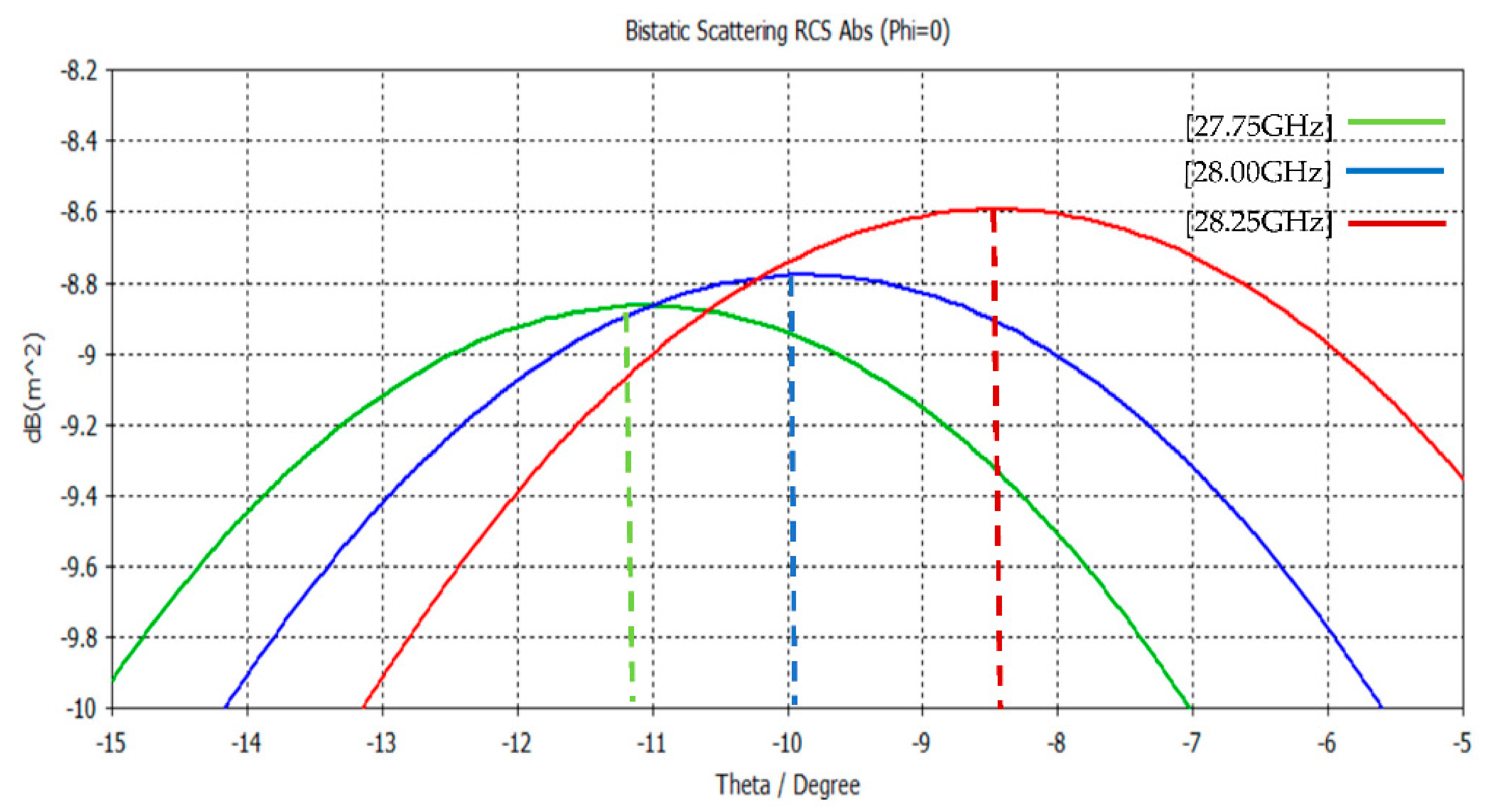
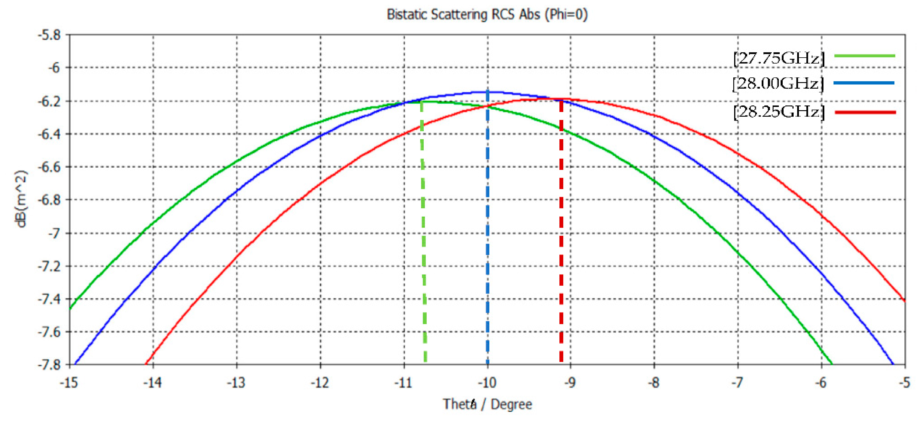
θ for different frequencies around the operating frequency (bandwidth) was obtained with the three-stripe configuration, compared to the typical uniform configuration (one stripe).
Figure 9 and
Figure 10 show the influence of a slight change in the operating frequency of the MS. The accuracy in the beam steering angle for the three-stripe configuration was about 50% better than for the typical one-stripe configuration. Far-field simulations indicated that the three-stripe configuration for a steering angle of θ = 10° showed an almost 0.7° difference (see
Figure 10) compared to the uniform one-stripe configuration, which was about a 1.2–1.4° difference (see
Figure 9) for the same frequencies.
Table 4 summarizes the bandwidth simulation results.
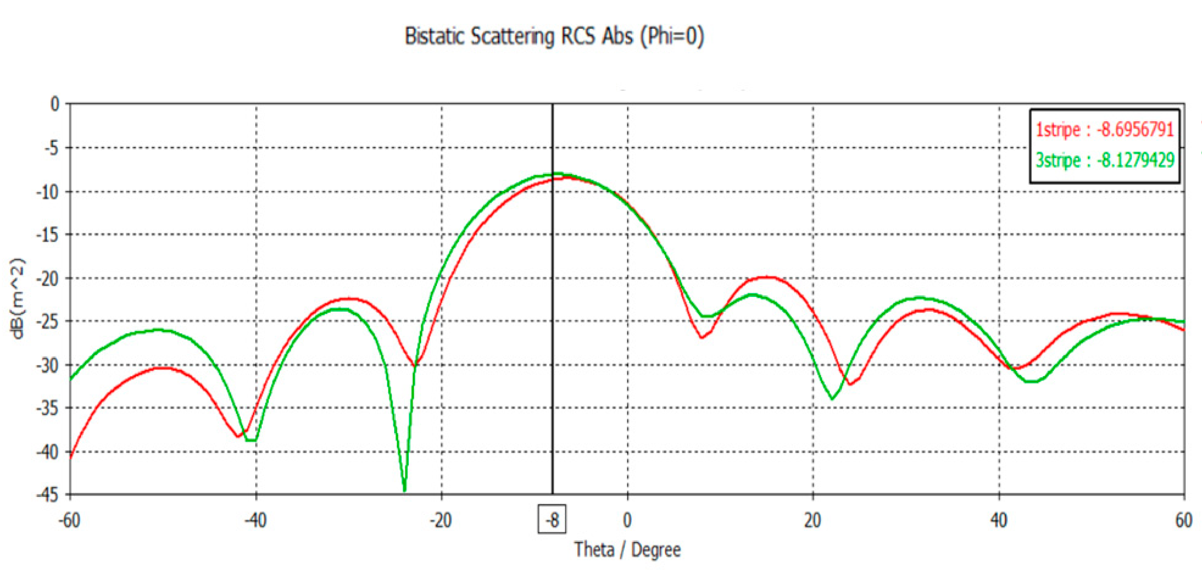
To demonstrate the advantages of the stripes method, the following combination was investigated: uniform–type A–uniform MS (three stripes method) compared to uniform MS (one stripe). Three performance parameters were simulated: reflected beam gain, SLL, and steering dynamic range.
Figure 11 shows the simulation of the reflected beam for 8 deg for three stripes (solid green line) and one stripe (solid red line). The performance of the reflected beam gain and SLL of the three-stripe configuration was higher by about 3 dB.
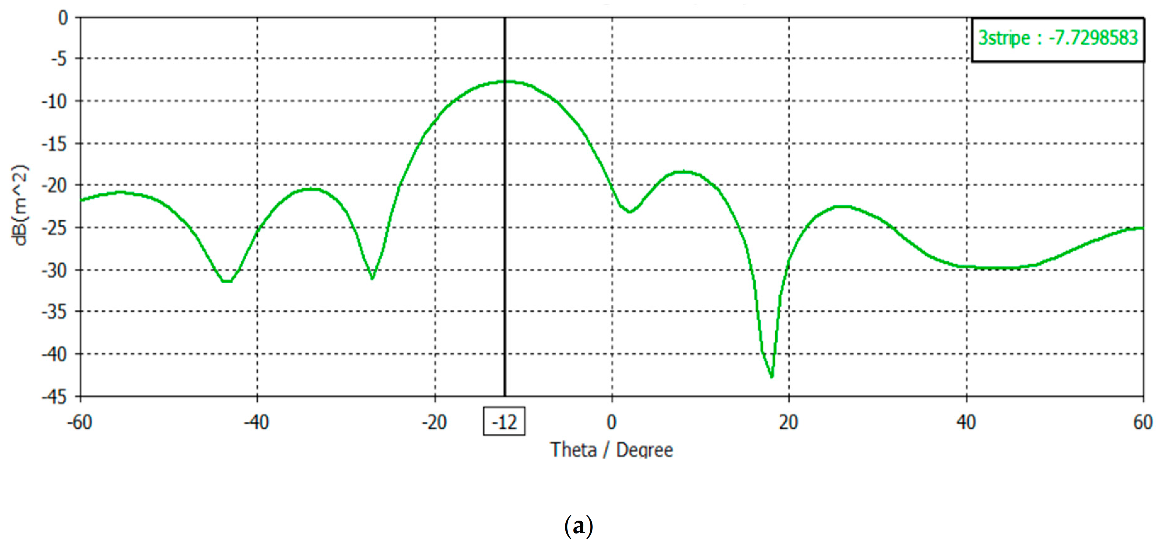
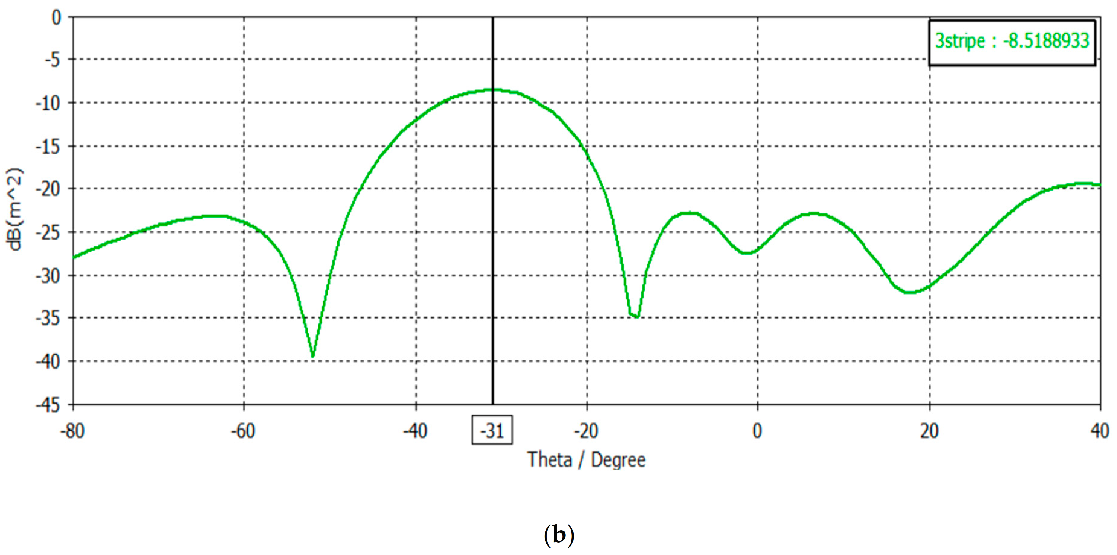
The phase dynamic range for 12° and 31° are given in
Figure 12. The three-stripe configuration composed of uniform–type A–uniform was able to cover a much larger dynamic range of the steering angle, as can be seen in
Figure 12, whereas the type A (one stripe) configuration was unable to realize this.
4. Discussion
The simulation results indicate that the three-stripe configuration proposed here yielded better performance compared to the common configuration (one stripe). Performance parameters such as reflected beam gain, SLL, beam-steering accuracy, and steering dynamic range showed better results.
Figure 7 shows a 3 dB better reflected gain and SLL for the three-stripe configuration in comparison to the common one-stripe configuration. The larger the beam-steering angle, the better the reflected gain, SLL, and bandwidth in the three-stripe configuration, compared to the one-stripe configuration. The reason for this is the smaller phase dynamic range of each stripe in the three-stripe configuration (type A and type B) compared to the one-stripe configuration where the phase dynamic range was larger (
Figure 4). In addition, another combination of the three-stripe configuration was investigated, in which the three-stripe configuration was again superior to the one-stripe configuration (
Figure 11 and
Figure 12). The accuracy of the reflected angle for different frequencies around the operating frequency (bandwidth) was found to be better for the three-stripe configuration compared to the one-stripe configuration, as shown in
Table 4. A 50% better accuracy was demonstrated (
Figure 9 and
Figure 10).
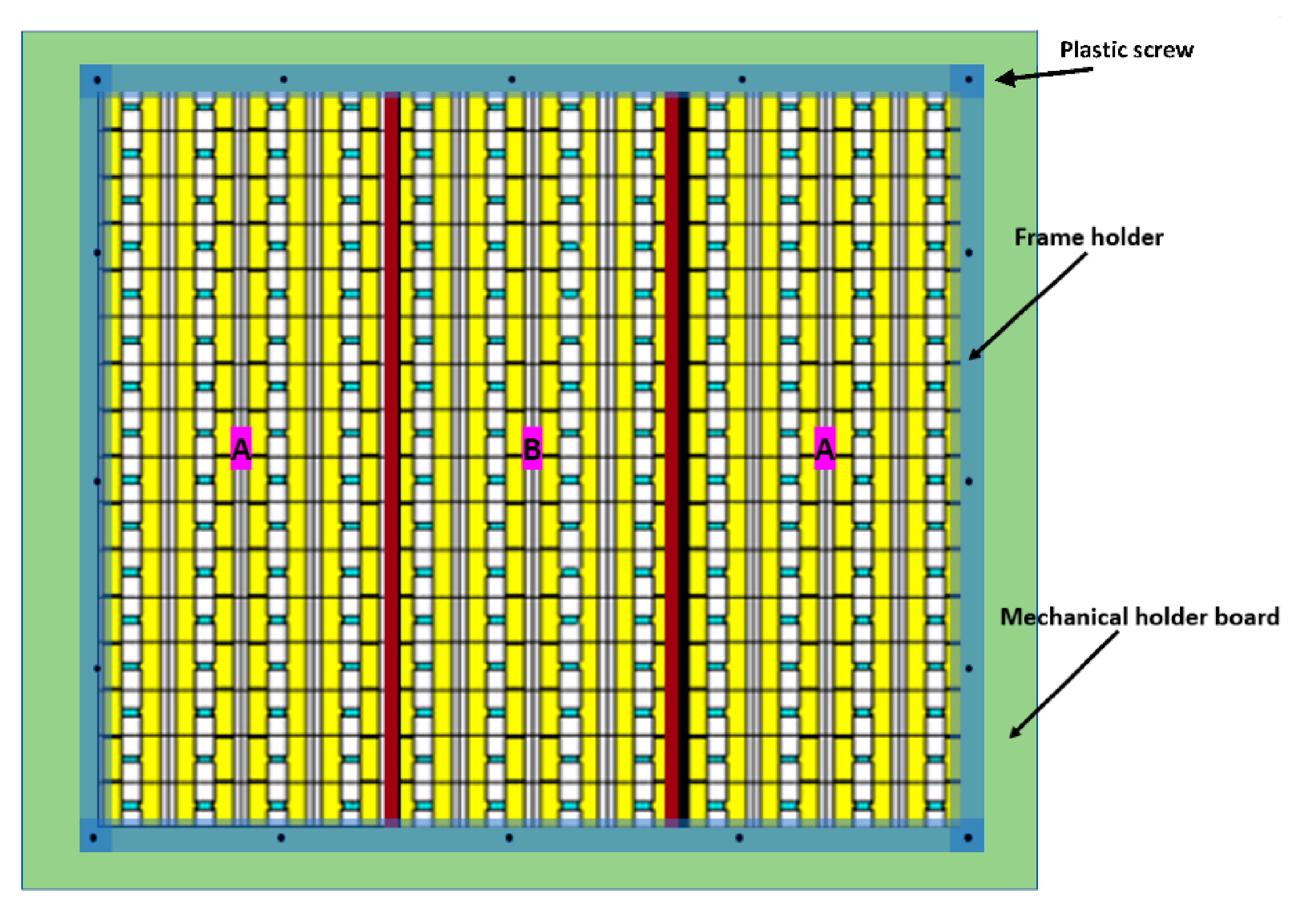
The construction of a three-stripe MS could be realized by using a plastic frame holder in the front and a plastic board on the back side for mechanical strength, as shown in
Figure 13. In
Figure 13, the incident beam “sees” the whole MS uniformly, aligned at Z = 0 (the front side of the MS). On the back side, it is different, but no effect on the reflected beam was found.


