1. Introduction
The rotor system is the core component of rotating machinery. To optimize and improve the dynamic performance, the dual-disk rotor system is widely employed in modern aero-engines [
1,
2]. It is more complicated than single-rotor systems in both the structural and dynamical regimes [
3,
4]. The analysis of traditional rotor dynamics is mostly based on deterministic models, which means that the parameters of the analysis object remain consistent. However, the physical parameters of the practical engineering mechanical always behave inherently in an uncertain way [
5,
6]. Component machining errors, installation gaps, uneven material distribution and fatigue during service are all typical sources of uncertainty [
7,
8,
9]. Dynamic responses of rotor systems must be non-deterministic due to the uncertainty. Therefore, it is necessary to consider the influence of uncertain factors in the design, development, production, and use of rotor systems.
In fact, researchers have paid attention to the uncertainty quantifications in the field of rotor dynamics. Zhu [
10] analyzes the stress-strain response induced by probabilistic plasticity with uncertainty. Giannella [
11] proposes a stochastic approach, which takes multiple sources of uncertainty into account, to predict the probability distribution of the residual fatigue life of a defective railway axle. Sinou [
12] applies the Kriging element model to predict the uncertain dynamic behaviors of flexible rotor system. Garoli and Castro [
13] consider the influence of temperature uncertainty on the bearing dynamic coefficient, and use polynomial chaos expansion to solve the oil film whirl instability problem of rotor-bearing system. The polynomial chaos expansion and the harmonic balance method is used to quantify the effects of different random parametric uncertainties on the linear and non-linear dynamical characteristics [
14]. The stochastic finite element method and the random variable model are adopted by Didier [
15] to obtain the statistical characteristics of the unbalanced response of the flexible rotor. The non-parametric modeling technology is discussed by Murthy [
16] on the unbalanced response and dynamic balance of the flexible rotor.
The probability density distribution of uncertainty is important to the dynamic research of rotor system with uncertainty. Whereas, for aero-engine rotor systems it is often difficult to obtain an accurate probability distribution of system uncertainty. In order to avoid the inability, scholars have proposed the concept of cognitive uncertainty and establish a variable probability model [
17]. A series of methods such as evidence theory, interval theory, and convex model are established by Jiang [
18,
19,
20] and Qiu [
21]. To quantify the uncertainty of dynamic systems with non-probabilistic interval numbers, Wu [
22] proposes Chebyshev inclusion function method by interval theory. The improved nonlinear Chebyshev method is applied by Ma [
23,
24] to carry out theoretical and experimental analyses on the bolted rotor system. Yang [
25] proposes a stable non-embedded interval method based on orthogonal polynomial approximation theory and precise integration method. Transient dynamics on the accelerating start process of the rotor system with interval uncertainty is studied, and vibration characteristics with cognitive uncertainties is obtained. Fu [
26] investigates the non-probabilistic steady-state dynamics of a dual-rotor system with parametric uncertainties under two-frequency excitations. However, the problem of uncertain rotor dynamics remains to be further studied, especially in the case of small samples. In addition, the calculation burden also needs to be reduced.
This paper introduces a convex model to describe the correlated interval variables of a dual-disk rotor system. And a non-probabilistic Chebyshev convex method is applied to obtain dynamic responses of dual-disk rotor system. The rest of the content is organized as follows. First, the finite element method for dual-disk rotor model and deterministic equations of motion will be described in
Section 2. Then, in
Section 3, the Chebyshev convex method (CCM) for dynamic analysis of uncertain rotors is explained. In
Section 4, the dynamic responses with uncertainty are achieved by CCM as well as experimental verification is carried out. Finally, the concluding remarks are drawn in
Section 5.
2. Dynamic Equation of Motion of the Rotor System
Finite element method (FEM) [
27] is an analytical method that simulates real system by mathematical approximation. At present, FEM has been widely used in the field of rotor dynamics. It plays an important role in solving the critical speed, unbalanced response, and harmonic response analysis of the rotor system. And it is also widely used in the design and evaluation of its structural integrity [
28,
29]. The basic idea of FEM is discretizing continuous elastic body into finite numbers of interactive elements. When the finite element model converges, the approximate solution will converge to the exact solution. In the finite element model, shape function is used to approximate the unknown field function in each element, adjacent elements are connected to each other by nodes, and force is also transferred from one element to another by the nodes interconnecting them, and deformation relationship between elements is determined by deformation coordination relationship. By establishing the mechanical relationship between nodal force and nodal displacement of elements, a group of equations with nodal displacement as an unknown variable is obtained, thereby the node displacement component can be obtained by solving the equations.
A typical rotor system is usually composed of some discrete discs, shaft sections, and bearing supports. When building the finite element model, nodes are generated at the center of the disc, the position of the bearing, the center of the journal, and some positions on the elastic shaft. Then the rotor system is divided into several elements along the axis.
2.1. Modeling the Elastic Shaft Element
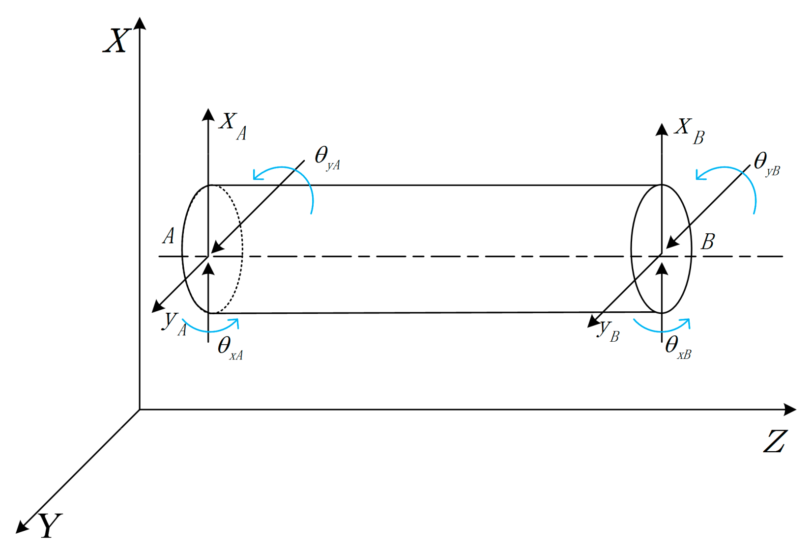
The main response mode of rotor system is bending vibration. Hence, the influence of the axial force and torsional vibration of the elastic shaft is not considered. The elastic shaft can be divided into multiple Euler-Bernoulli beam elements that do not consider the influence of the shear deformation.
Figure 1 shows an elastic shaft element. The nodal displacement vector can be defined as
in fixed coordinates frame.
Based on Lagrange equation, the rotor motion equation can be established by FEM. The differential equation motion of elastic shaft element is
where, [
Ms] is the uniform mass matrix, Ω is the rotate speed of the shaft element, [
Js] is the rotary matrix and [
Ks] is the rigidity matrix, [
Fs] is the generalized force matrix.
It should be noted that the different coordinate order will cause different [Ms], [Js] and [Ks], but the same result of U can be obtained after transformation.
2.2. Modeling the Rigid Disk
When the disc on the shaft only affects inertia characteristics but does not affect stiffness characteristics of the element, it can be treated as a rigid disk or a concentrated mass element.
Assuming that the axis of the disk coincides with the center of gravity, the nodal displacement vector of the disk element in generalized coordinate is
Based on Lagrange equation, the differential equation motion of rigid disk is
where, [
Md] is mass matrices for rigid disks, [
Jp] is the rotary matrix, and {
Fd} is the corresponding generalized concentrated force on the generalized concentrated mass element.
2.3. Mathematical Model of Flexible Rotor System
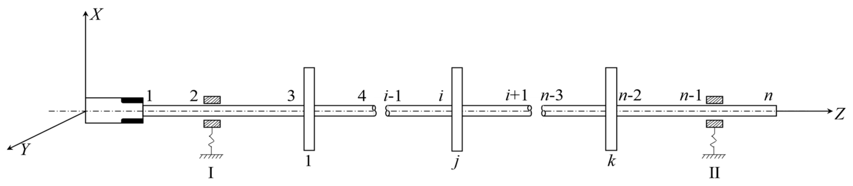
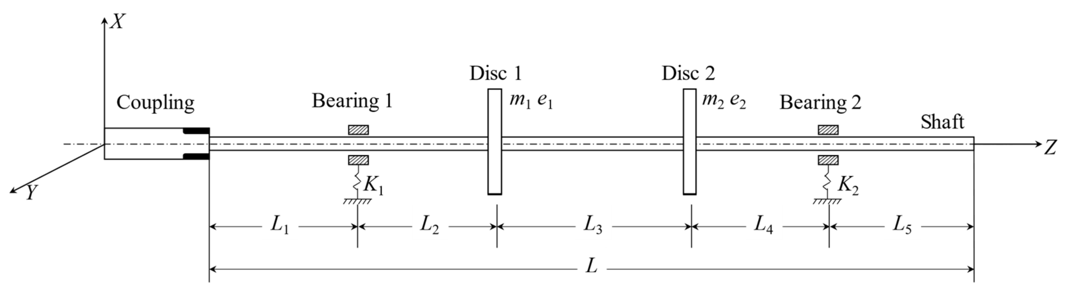
A rotor system structure diagram is shown in
Figure 2. It consists of a shaft, two elastic bearings, and several disks. According to the FEM, the high-speed flexible rotor system is divided along the axial direction into
n−1 shaft elements,
k disks, and two bearings.
The rotor system with
n nodes connected by
n − 1 finite elements. The displacement vector of the system is
Establish the differential equation motion of rotor system by Equations (1) and (3), and shown as follows:
The differential equation of motion of the rotor system changes to
where, [
M] is the global mass matrix, [
C] is the damping matrix, Ω[
J] is the rotary matrix, and [
K] is the rigidity matrix. They are symmetric banded sparse matrix with order of 4
N ×
N. {
F} is the generalized external force matrix, and is the column matrix with order of 4
N × 1.
3. The Chebyshev Convex Method for Dynamic Analysis
In this section, the ellipsoidal convex model is used to quantify the uncertainty. And the Chebyshev expansion function is introduced to analyze the dynamic response of the rotor system. Convex model is different from traditional interval model. It does not require precise probability distribution models or fuzzy membership functions of parameters, but only the upper and lower boundary of uncertain parameters. Meanwhile, the correlation between uncertain parameters is considered by convex model. Compared with perturbation technique or Taylor expansion, it is not limited by small uncertainty. The overestimation caused by the wrapping effect is also controlled effectively [
30]. Chebyshev expansion function is an approximate proxy model. It uses Chebyshev series expansion method to obtain the solutions of differential equations at interpolation points. It can be used to characterize the response function of the original system, and has advantages of short calculation time, good calculation efficiency, and high calculation accuracy. Combining the ellipsoidal convex set model and Chebyshev expansion function, the Chebyshev convex method (CCM) is proposed to analyze the multi-convex uncertain system response.
3.1. The Ellipsoid Convex Method for Uncertain Parameters of Rotor Systems
The ellipsoid model is the most extensive among the convex models with the advantages of rounded boundaries and compact uncertainty regions. The multi-ellipsoid model is applied to describe the finite-dimensional distribution of the convex model process.
The
n-dimensional interval variable is usually denoted as
.
X represents an uncertain parameter. In FEM model, it is the value in the [
M], [
C], [
K] and [
J] of Equation (7). The uncertain region of
is expressed as a region contained by an
n-dimensional hyper-ellipsoid as follows:
The region contained by
is an
n-dimensional ellipsoid model, assuming that all possible values of uncertain parameters are contained in ellipsoid.
X is the ellipsoid convex variable,
Xm is the median value of a convex variable, and
We is the characteristic matrix of ellipsoid model. It determines the size and shape of the ellipsoid model and can represent the correlation between variables.
When the axis of the ellipsoid is along the direction of the coordinate axis, We becomes a diagonal matrix.
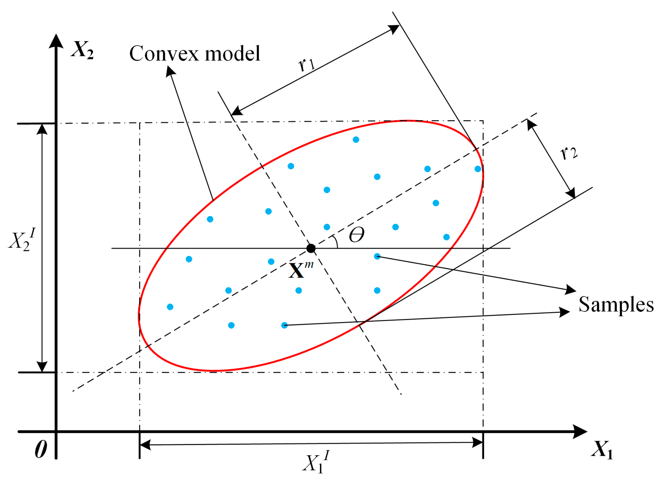
As an example, the geometric characteristics of the ellipsoid model are studied, taking the two-dimensional ellipse in
Figure 3. The geometric quantity is required to determine an ellipse: elliptic central coordinates
; length of semi-major axis
; length of short half axis
; and the angle between the major axis of the ellipse and the
X1 axis is donated as
θ(−45° <
θ < 45°). To facilitate the solution, the mean value, variance, and covariance of the ellipse are usually used to describe the geometric characteristics of the ellipse [
31,
32].
The ellipsoid convex model describes the uncertain parameters in the rotor system. The differential equation of the convex uncertain rotor system is
From the convex variable
X, the response interval form of the uncertain rotor system is
where
3.2. Chebyshev Method for Convex Analysis of the Rotor Dynamic Response
In this section, a Chebyshev interval expansion function based on the Chebyshev series expansion is proposed.
Considering functions in the ellipsoid as follows:
Function
f (
x) can be approximated by Chebyshev polynomials.
where,
P is the order of Chebyshev polynomials,
fi is the constant coefficient of Chebyshev polynomials
Ci.
For an
n-dimensional problem, the Chebyshev polynomials are defined as
where,
ki (
I = 1, 2, …,
n) is the nonnegative integer,
θi (
I = 1, 2, …,
n) is a function of the convex variable.
The truncated Chebyshev polynomial of function
f(
x) can be rewritten as
According to the Mehler integral method,
fi can be calculated by Equation (18).
Coefficient
is expressed as
where,
m is the number of sampling points that need interpolation in each dimension,
l denotes the total number of zeros in subscript
.
Chebyshev polynomial surrogate model of
n-dimensional function
f(
x) are defined as
The differential Equation (10) of the convex uncertain rotor system can be solved based on Equation (21).
The extreme values of the response
U can be found as follows:
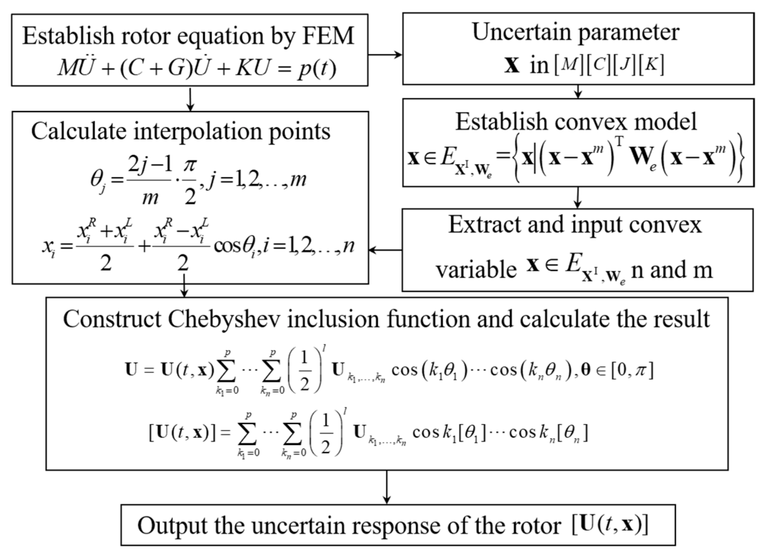
The computational flowchart of the framework is demonstrated in
Figure 4.
4. Numerical Analysis of the Rotor Dynamic Response Based on CCM
In this section, some simulations are carried out taking the high-speed flexible rotor as an example. The characteristic of the model is introduced and the deterministic response of the rotor system will be given first. To verify the reliability and stability of the CCM, the transient response of rotor system with correlated uncertain parameters is calculated and compared with the results calculated by CMCS. After that, experiment is conducted to verify the correctness of the simulation results. According to the results of numerical simulation and experiment, some preliminary discussions are made.
4.1. Numerical Simulation Model and Deterministic Response
As shown in
Figure 5, the rotor system is modeled by beam element, mass element, and spring element with convex variable parameters. Detailed deterministic geometric and physical parameters of the rotor system studied are given in
Table 1.
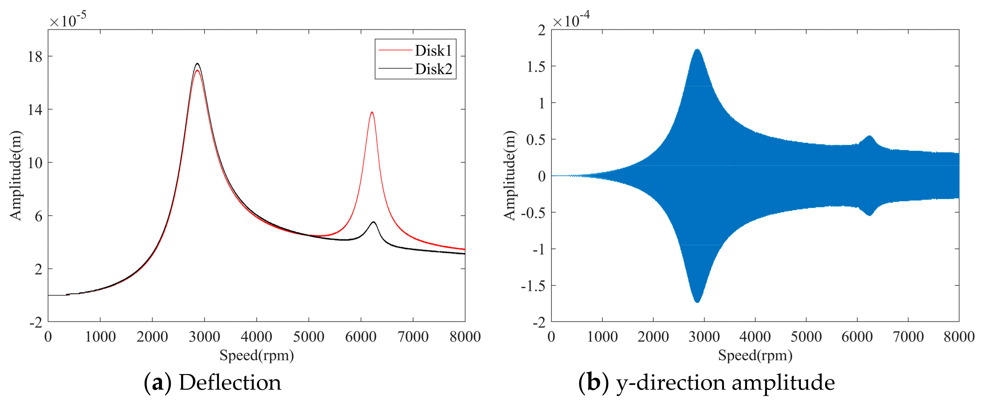
The deterministic response is illustrated to characterize the dual-disk rotor system without uncertainty and to give an initial impression of its dynamic behaviors. Based on the deterministic model and numerical simulations, the first three critical speeds of the rotor are shown in the
Table 2 and the transient-state vibration amplitude time when the two disks rotate at the same time, history of the disk geometric center is shown in
Figure 6.
By observing the value of the first three critical speeds and deterministic response of the dual-disk rotor, it can be found that the rotor system has two critical speeds in the working speed range, and the first two peaks appear at 2838.67 rpm and 6406.81 rpm for both of the disks, respectively. Meanwhile, the second-order peak of disk 1 is significantly greater than that of disk 2. This phenomenon is analyzed by researchers and could be attributed to the different stiffness of bearings [
33,
34,
35]. Moreover, the response law of the two disks is basically similar. The vibration state at the critical speed satisfies the actual operating law of the rotor system. In order to simplify the analysis process, the subsequent uncertainty analysis only analyzes disk 2.
4.2. Single Parameter Uncertainty
When there is a single uncertain parameter, the convex model evolves into an interval model. By the Chebyshev Convex Method (CCM), the uncertainty caused by the uncertain coefficient can be acquired. Several uncertain parameters are considered below, and the response boundary of the critical speeds calculated by CCM are compared with those by CMCS. In order to compare the influence of different single parameters of the rotor system, parameters are defined in same uncertain degree. According to the actual needs of the project, the degree of uncertainty is set to 10%.
Firstly, the damping is viewed as an uncertain parameter, and the degree of uncertainty is 10%. Using CCM, the uncertain dynamic response affected by uncertain parameters can be obtained, and the results are shown in
Figure 7.
Compared with CMCS, the response boundary in the critical speed range calculated by CCM is similar, and the deterministic transient response curve of the system is symmetrically shifted up and down. The resonance peak position does not change and falls within the critical speed range.
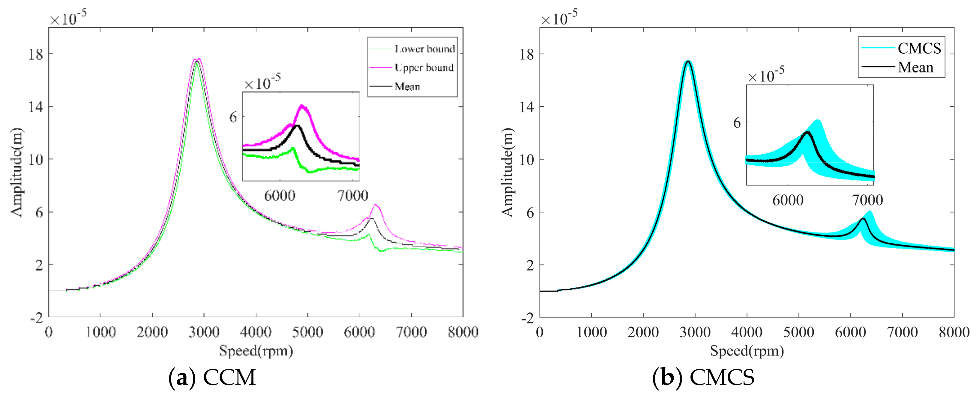
Generally, it is difficult to define the accurate value of the stiffness of a support. In this case, the stiffness of bearing 2 is taken as a convex variable to cover its variability and the uncertain degree of support stiffness
K2 is 10%. The response range of the center of disk 2 is shown in
Figure 8.
As can been seen from
Figure 8, we can find that there is a peak shift in second-order resonance peaks under the influence of the support stiffness uncertainty at no such phenomenon in the first-order. This means the different sensitivities of the system in different speed ranges to the first two critical speeds. Meanwhile, the upper and lower boundaries of the deflection amplitude increase at the peak of the second-order critical speed, which suggests that the inherent properties of the high-speed flexible rotor system are sensitive to the support stiffness. In addition, due to the simplification of the model and the calculation method in the theoretical analysis, the theoretical modeling cannot fully simulate the actual structure of the original high-speed flexible rotor system, resulting in small errors and overestimation of response.
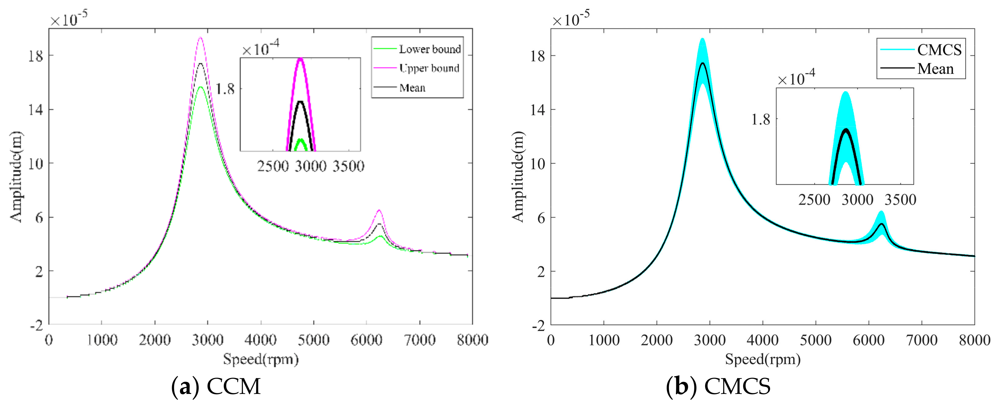
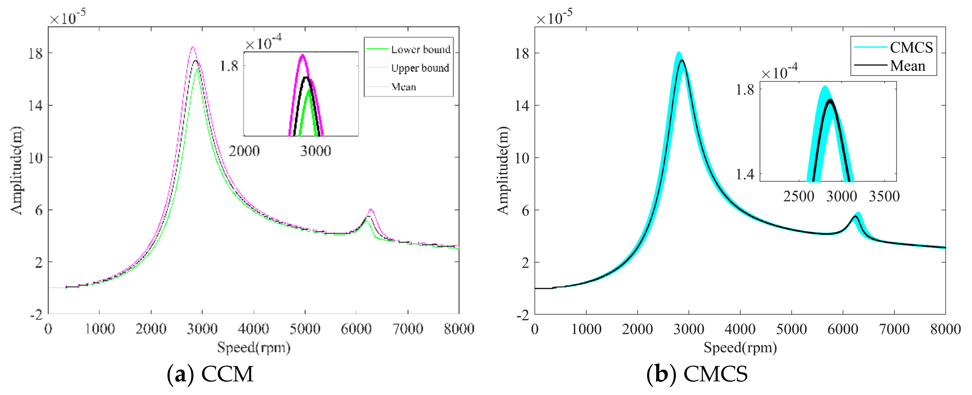
In engineering practice, the rotor system may be affected by manufacturing error, material degradation, and wear. The actual mass often deviates from the theoretical value after long-term work. Therefore, the uncertainty of mass should be considered in the analysis. To consider the uncertainty of mass, the uncertain degree of mass of disk 2 is taken to be 10%. The ellipsoidal convex model is used to solve the analysis interval response, and the results are shown in
Figure 9.
The uncertainty of rotor disk mass leads to the deviation of system response in the whole speed range as show in
Figure 9. More specifically, compared with the deterministic peak, the first peak of the uncertainty response shifts to the left and the second peak shifts to the right. That means the double rotors are very sensitive to the disk mass, which can be used as a key factor in the design and maintenance of such engineering systems. The results of the CCM also show that the upper and lower boundary gauges completely encapsulate the deterministic response values.
Figure 7,
Figure 8 and
Figure 9 show that the accuracy of CCM results is related to the sensitivity of critical speed to parameters. In the whole response range, the interval response results calculated by CCM are stable. Compared with the deterministic response results, the actual operating conditions of the rotor system can be well reflected. The resonance peaks under different uncertain parameters are calculated and recorded in
Table 3. Comparing the error caused by the parameter uncertainty at the peak of the first-order critical speed and the second-order critical speed under the same uncertainty, it can be seen that the error at the second order is significantly greater than that at the first order. This demonstrates that the peaks in the second-order critical speed range are more sensitive to parameters than the first-order peaks. And compared with the results of CMCS, CCM can have a good interval wrapping effect. Meanwhile, in order to verify the computational efficiency of CCM, the calculation of the mass uncertainty response results is taken as an example, and the computer time consumption of the two methods at the same calculation environment is given in
Table 4. Obviously, it can be seen that the calculation time of Chebyshev method based on CCM is much shorter than that of CMCS and the computing efficiency is significantly improved.
4.3. Multi-Parameters Uncertainty
This subsection pays attention to the influences of multi uncertain parameters [
33] on the dynamic behaviors of the dual-disk rotor. Consider the uncertainties in the supporting stiffness
K2, damping
C and mass
m2 of disk 2 that studied in the previous subsections, in which the supporting stiffness
K2 and damping
C are correlated uncertain parameters, and the disk mass
m2 is an independent parameter. The uncertain degrees are 10% for the uncertain parameters. The deflection curves of rotor system calculated by CCM and CMCS are shown in
Figure 10.
Comparing the curves of
Figure 7 and
Figure 10 to
Figure 9, at the same uncertainty degree, the overall envelope range caused by multi-parameters uncertainty is significantly wider than that caused by single parameter uncertainty. The peak shifts are observed at the critical speeds. It shows that the dynamic response is significantly affected by the multiple uncertain parameters.
4.4. Critical Speeds Uncertainty
This subsection pays attention to the critical speeds influenced by uncertainty of the rotor system. The elastic modulus
E, material density
ρ, and support stiffness
K2 are regarded as uncertain parameters. Among them, the elastic modulus
E and material density
ρ are related. The first three critical speeds influenced by different uncertain parameters are calculated when the uncertain degree is 10%. And the calculation results are recorded in
Table 5.
It can be concluded from
Table 5 that the critical speeds of the rotor system are no longer fixed values, but change within an interval. Comparing the errors of critical speeds influenced by different uncertain parameters, it can be seen that errors effected by multi- parameters are greater than those caused by single parameters.
The first three critical speeds influenced by uncertain multi-parameters are calculated when the uncertain degrees are 10% and 15% respectively. And the calculation results are recorded in
Table 6. Comparing the critical speed interval errors under different uncertainty, the error on the critical speeds increases accordingly with the increase of uncertainty.
4.5. Experimental for Uncertainty Response
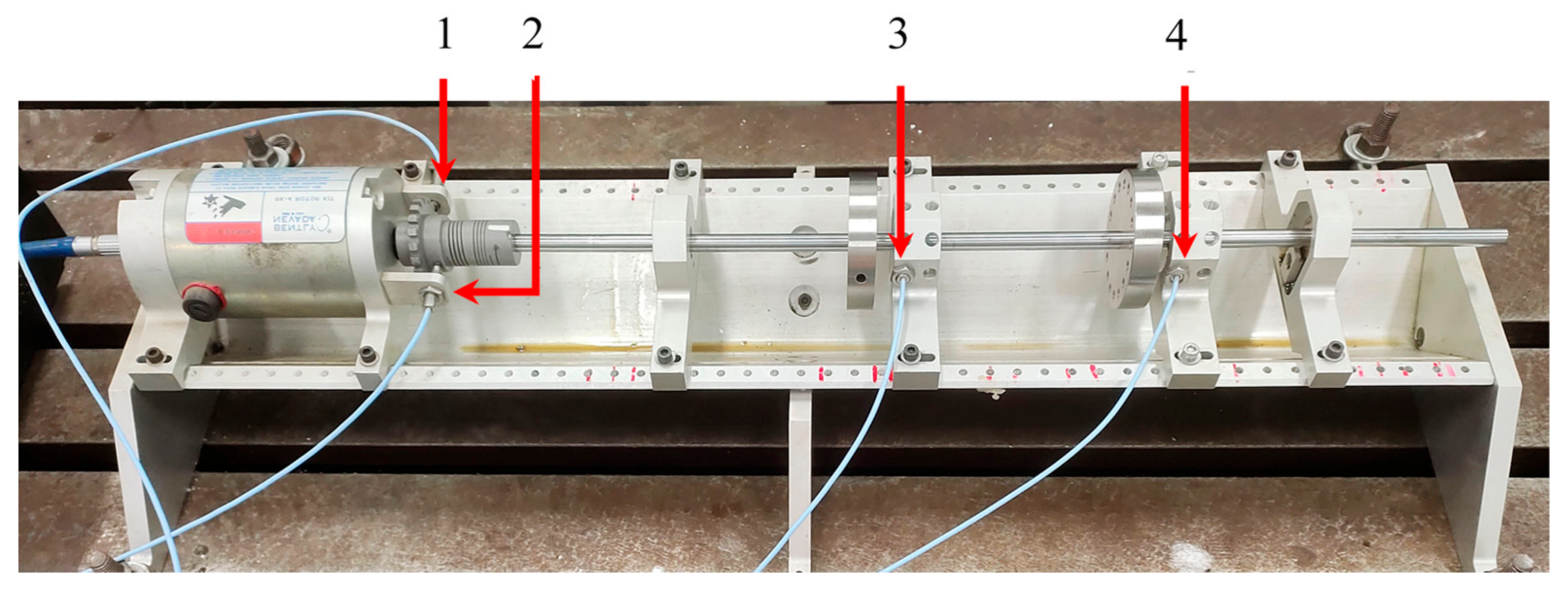
The dual-disk rotor system shown in
Figure 11 is used for the uncertainty response experimental, and the physical parameters of the rotor are tabulated in
Table 1. The rotor system consists of a straight shaft and two discs overhung on the right. The shaft is fixed on the bracket by two bearing supports, and the left end of the shaft is connected with the drive motor by the coupling. The maximum speed of the motor is 10,000 r/min. The two displacement sensors (NO. 3 and 4 in
Figure 11) are arranged horizontally on the right side of the bearing supports of the discs to measure the dynamic displacement of the rotor. And the rotor speed is measured by two displacement sensors (NO. 1 and 2 in
Figure 11) which receive the displacement information on the coupling. The deflections of the discs are obtained by Hilbert transform under the condition of neglecting the anisotropy of rotor.
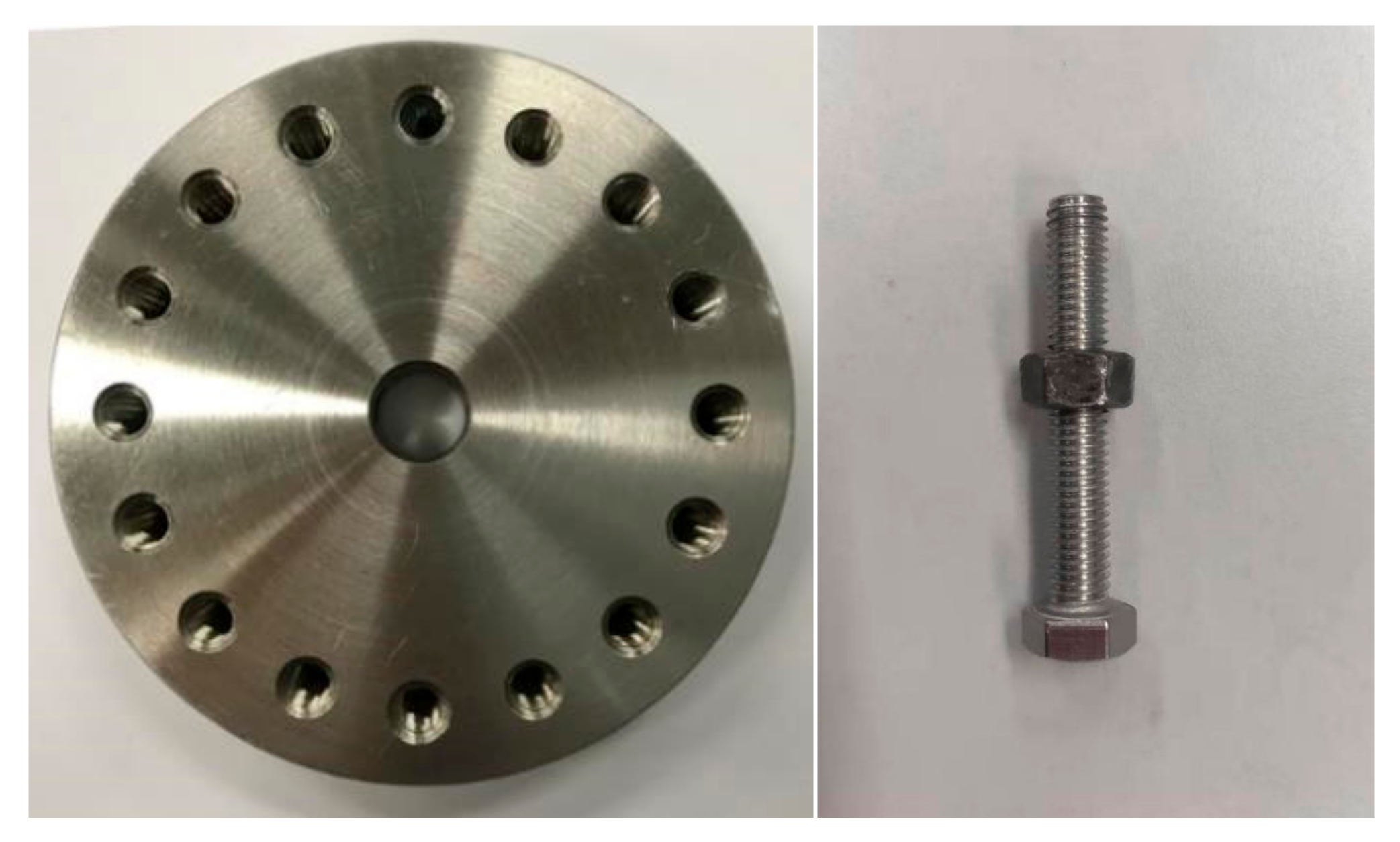
In order to verify the effectiveness of CCM, the uncertainty experiment of mass parameter is carried out. The simulation of mass uncertainty is realized by adding screws to the disk. The screws shown in
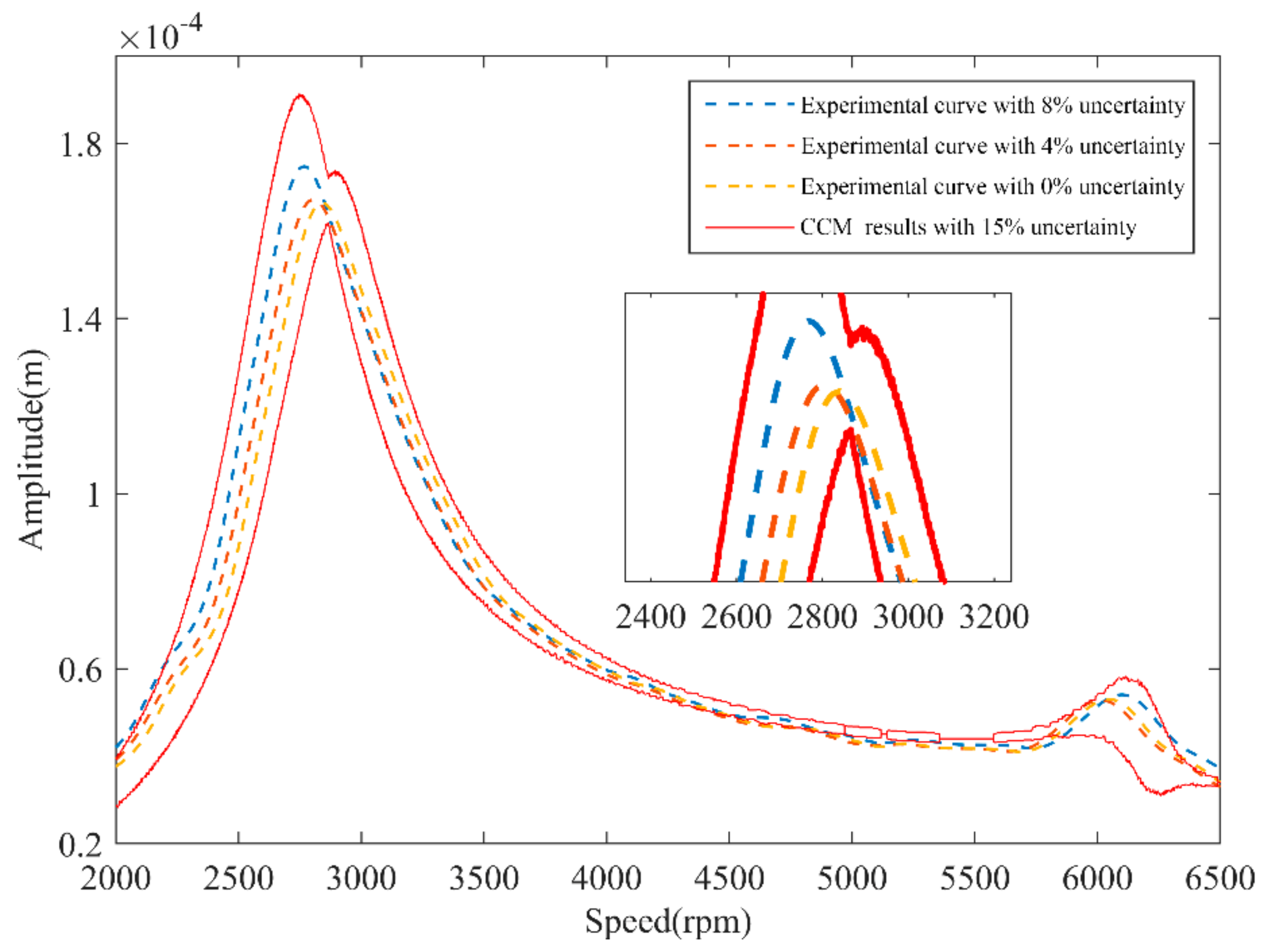
Figure 12 with the weight of 4.73 g are inserted into symmetrical holes on the disk 2 to simulate the change of mass (4 screws correspond to the mass uncertainty of 4% and 8 screws correspond to the mass uncertainty of 8%). Due to the existence of uncertainty, the dynamic response of the system can be any possible value in the response interval. Compare the vibration response of disk 2 measured by the experiment with the numerical simulation results, and the results are shown in
Figure 12.
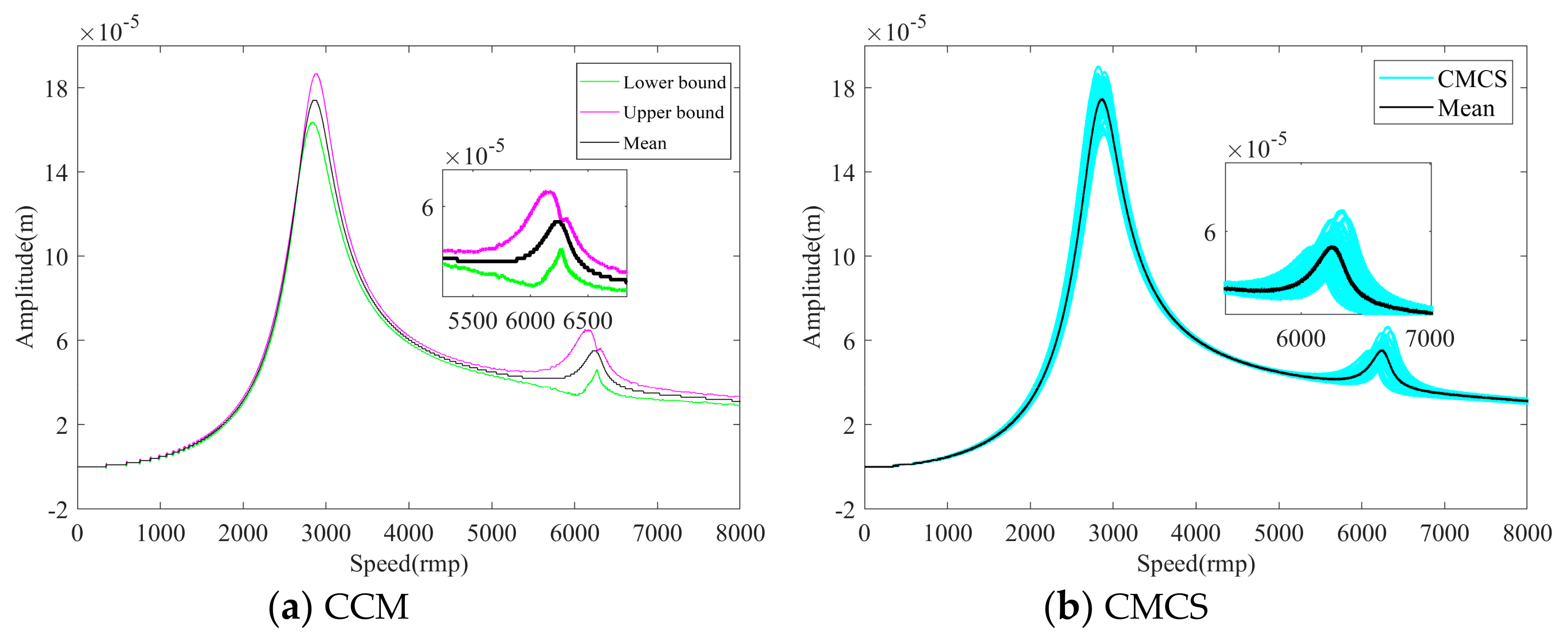
Comparing the experimental results of dual-disk rotor system with the simulation results shown in
Figure 13.
The red solid lines in the
Figure 13 are the upper and lower bounds of the rotor system simulation results when the uncertainty is 15%. It can be seen that when the uncertainty is 4%, 8%, and no uncertainty, the peaks of the experimental deflection curves are surrounded by the simulation results. Meanwhile, the experimental results show that with the increase of mass uncertainty, the resonance peaks of the deflection curves shift to the left in the first critical speed range and shift to the right in the second critical speed range. The trend of simulation results is consistent with experimental result when the mass is uncertain. In addition, the slight frequency shift and interval overestimation can be observed at the second-order critical speed. This is because theoretical modeling cannot fully simulate the actual structure of the high-speed flexible rotor system, resulting in errors in response calculations. In general, the experimental rotor response is basically contained in the simulation uncertainty interval, which proves the reliability and stability of CCM.


