
Electrochemical Synthesis of Nano-Sized Silicon from KCl–K2SiF6 Melts for Powerful Lithium-Ion Batteries

 , , , , , and
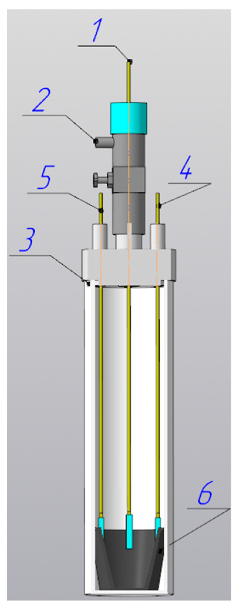
Abstract
:1. Introduction
2. Materials and Methods
3. Results
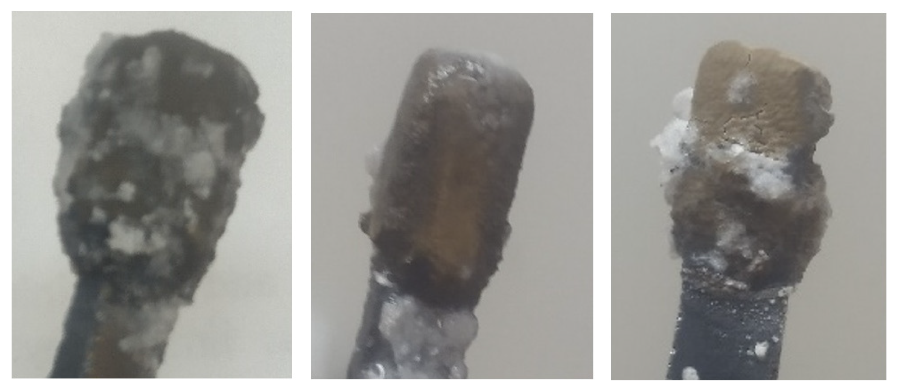
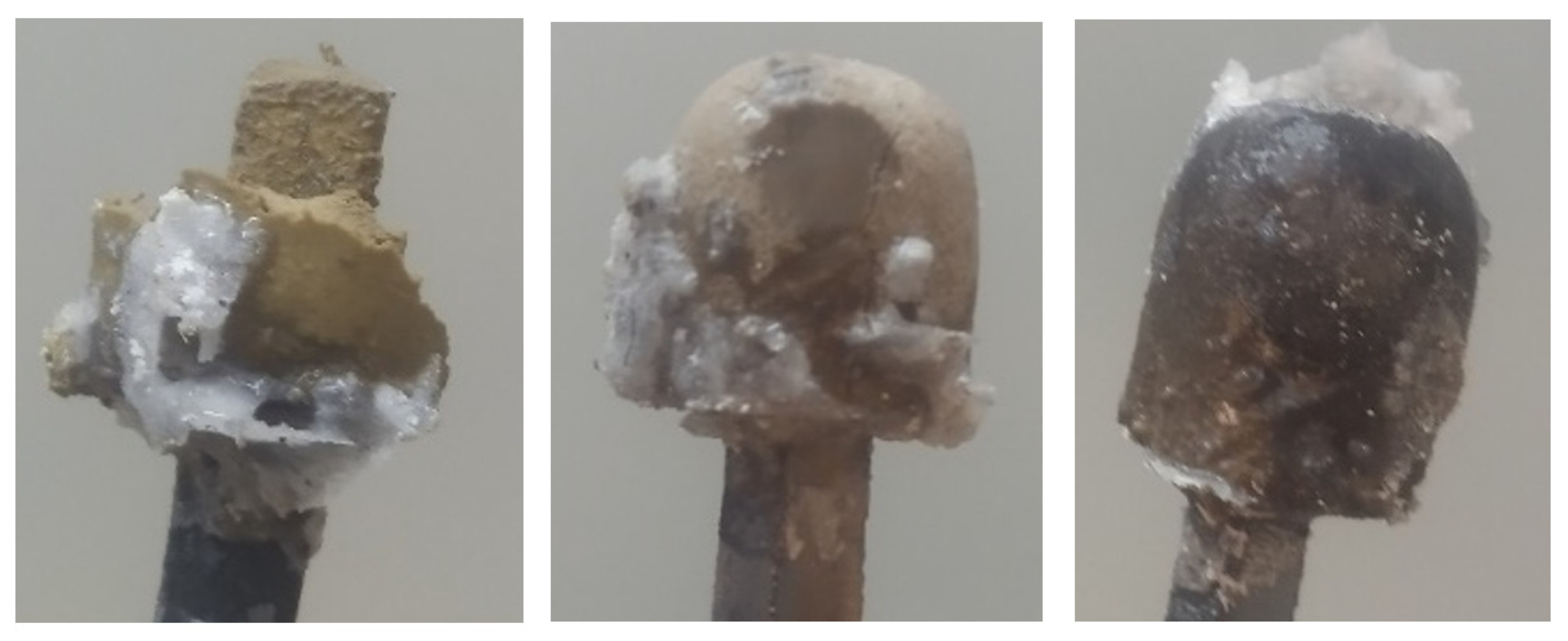
3.1. Electrolysis Test Results
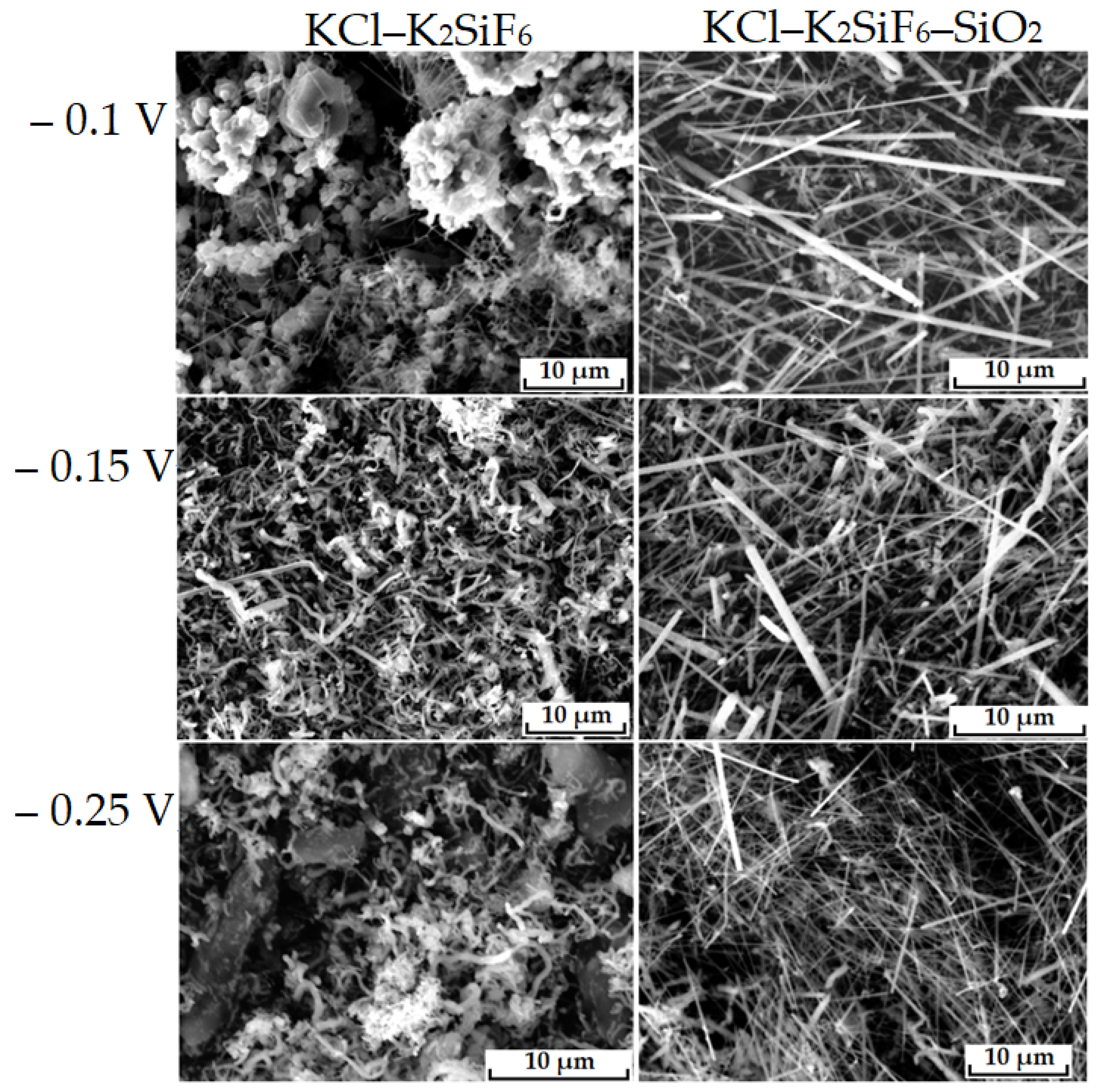
3.2. Effect of SiO2 on the Morphology of Silicon Deposits
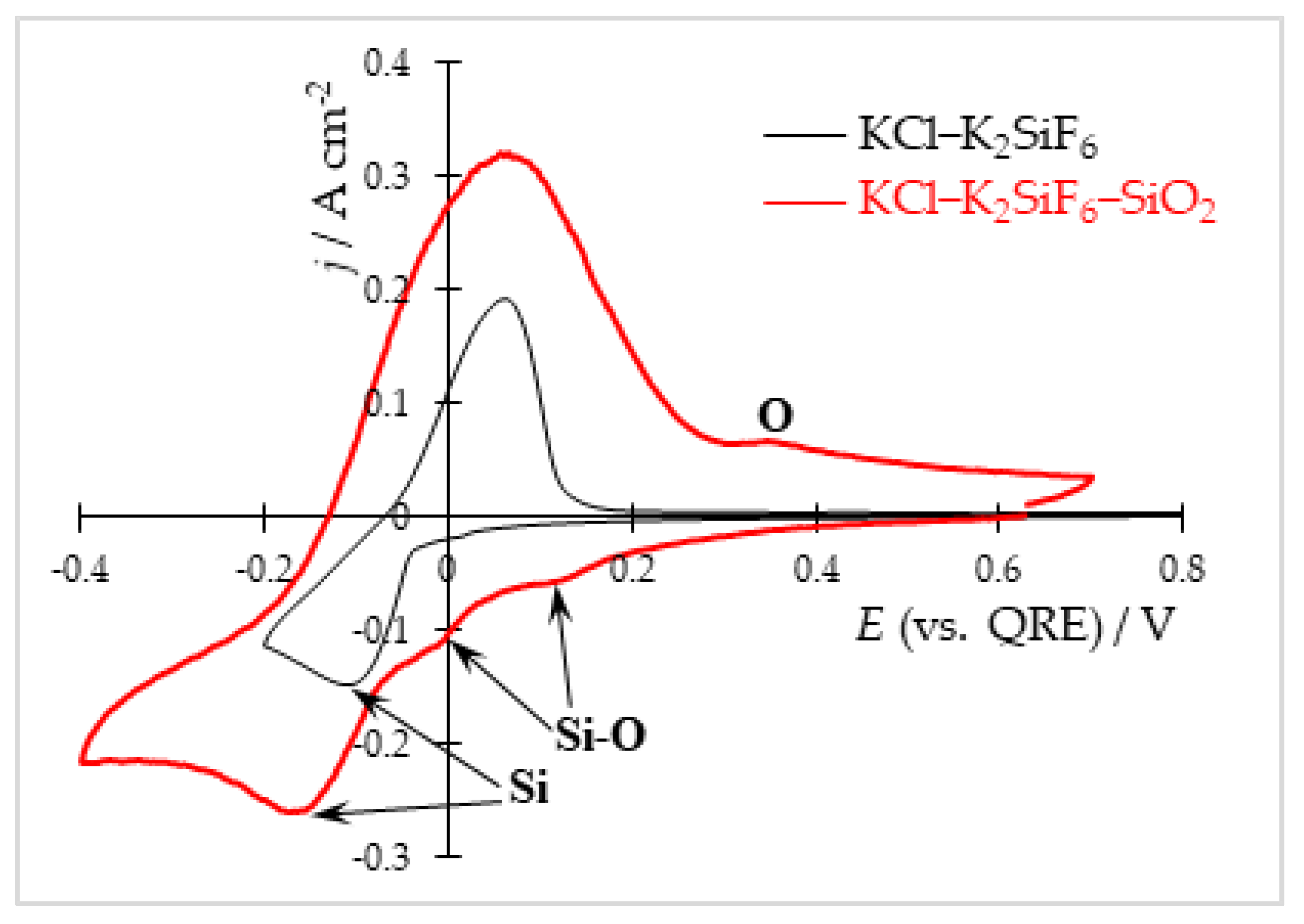
- (1)
- a change in the composition of silicon-containing electroactive particles, namely the inclusion of oxygen atoms in their composition, leading to a decrease in binding energy of silicon atoms [51] and facilitation of the charge transfer stage;
- (2)
- a decrease in electrical conductivity (increase in resistance) of the near-cathode layer melt, which will redistribute the current lines among the cathode surface. Namely, silicon electrodeposition will occur at the tips of the deposit, rather than on the lateral surfaces;
- (3)
- a change in the composition of silicon-containing electroactive ions, as a result the ions activity and the rate constant of the possible preceding chemical reaction in the melt change.
3.3. Effect of SiO2 on the Kinetics of Silicon Electrodeposition
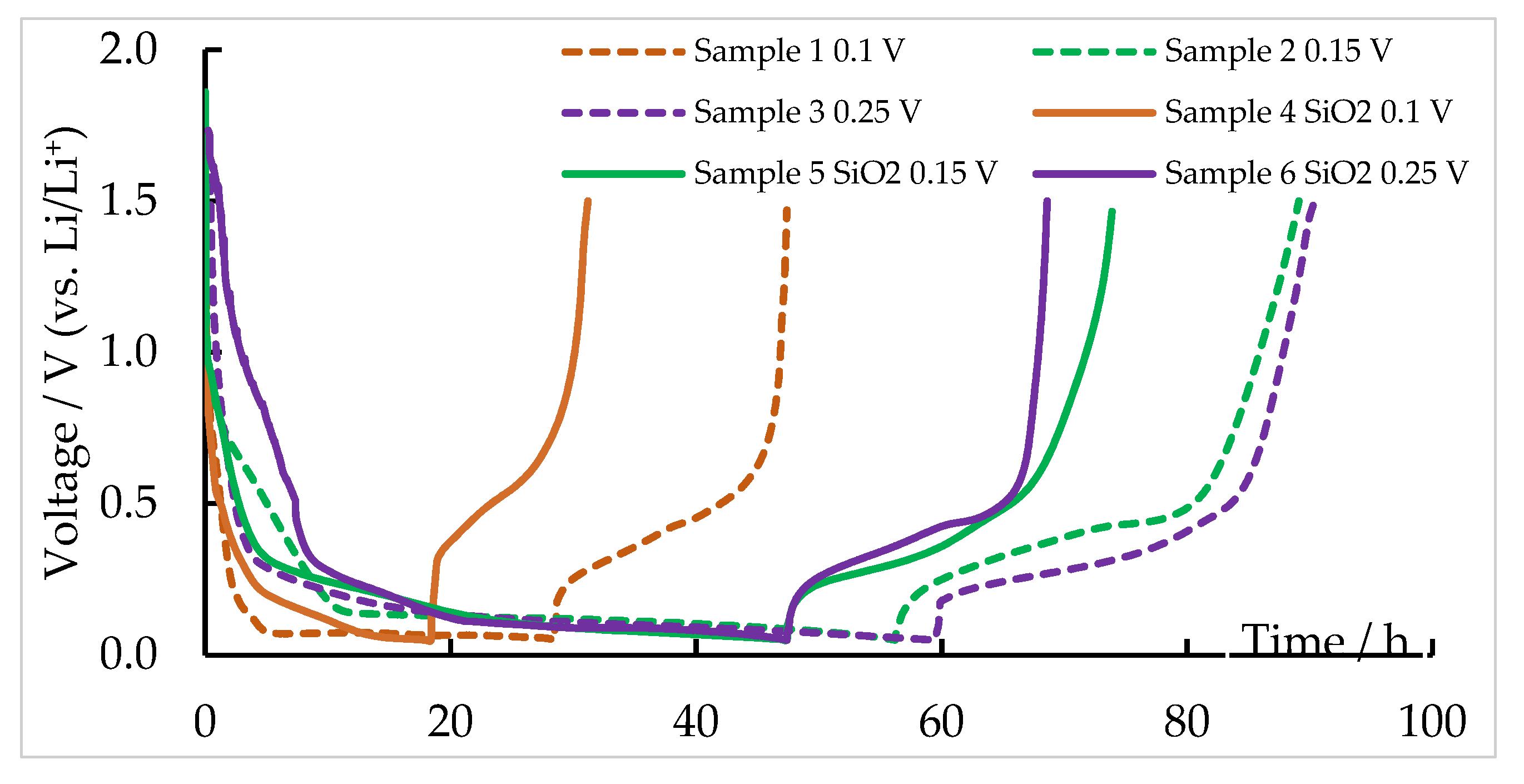
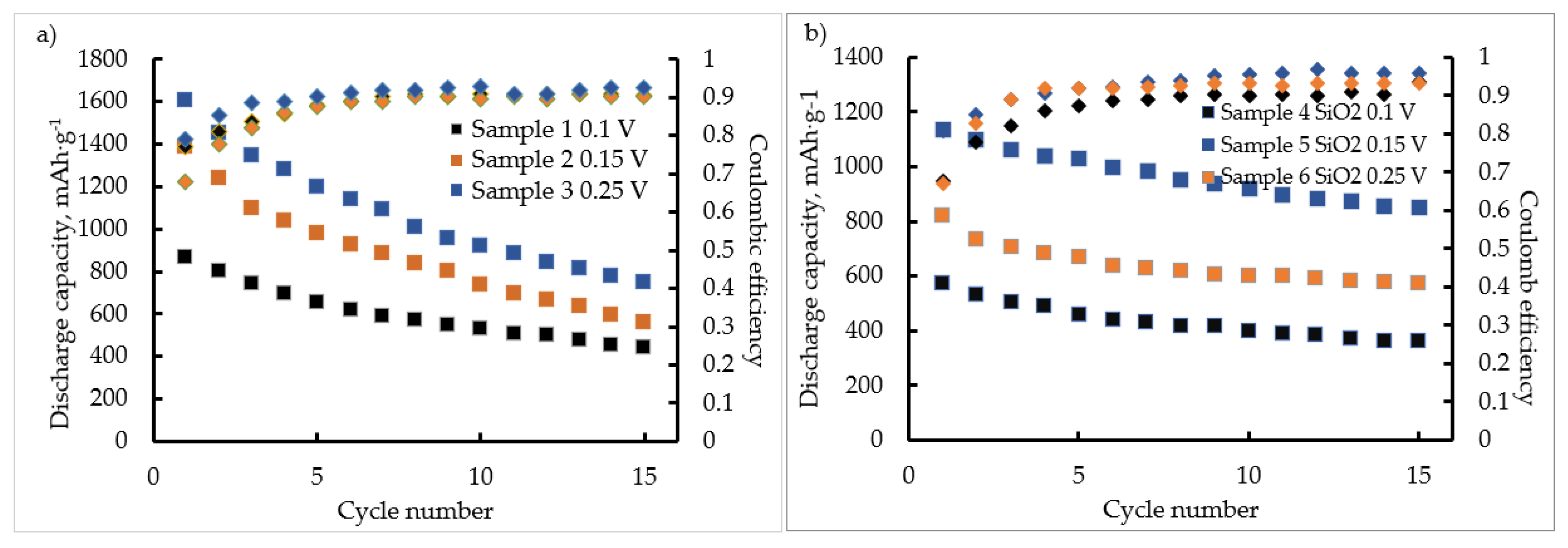
3.4. Electrochemical Characteristics of the Obtained Silicon Deposits
4. Conclusions
Author Contributions
Funding
Institutional Review Board Statement
Informed Consent Statement
Acknowledgments
Conflicts of Interest
References
- Cohen, U. Some prospective applications of silicon electrodeposition from molten fluorides to solar cell fabrication. J. Electron. Mater. 1977, 6, 607–643. [Google Scholar] [CrossRef]
- Liu, Z.; Sofia, S.E.; Laine, H.S.; Woodhouse, M.; Wieghold, S.; Peters, I.M.; Buonassisi, T. Revisiting thin silicon for photovoltaics: A technoeconomic perspective. Energy Environ. Sci. 2020, 13, 12–23. [Google Scholar] [CrossRef] [Green Version]
- Feng, K.; Li, M.; Liu, W.; Kashkooli, A.G.; Xiao, X.; Cai, M.; Chen, Z. Silicon-based anodes for lithium-ion batteries: From fundamentals to practical applications. Small 2018, 14, 1702737. [Google Scholar] [CrossRef] [PubMed]
- Galashev, A.Y.; Suzdaltsev, A.V.; Ivanichkina, K.A. Design of the high performance microbattery with silicene anode. Mater. Sci. Eng. 2020, 261, 114718. [Google Scholar] [CrossRef]
- Schmidt, H.; Jerliu, B.; Hüger, E.; Stahnc, J. Volume expansion of amorphous silicon electrodes during potentiostatic lithiation of Li-ion batteries. Electrochem. Commun. 2020, 115, 106738. [Google Scholar] [CrossRef]
- Wu, J.J.; Chen, Z.; Ma, W.; Dai, Y. Thermodynamic estimation of silicon tetrachloride to trichlorosilane by a low temperature hydrogenation technique. Silicon 2017, 9, 69–75. [Google Scholar] [CrossRef]
- Zhang, C.; Wang, F.; Han, J.; Bai, S.; Tan, J.; Liu, J.; Li, F. Challenges and recent progress on silicon-based anode materials for next-generation lithium-ion batteries. Small Struct. 2021, 2, 2100009. [Google Scholar] [CrossRef]
- Zhao, Y.; Yue, F.; Li, S.; Zhang, Y.; Tian, Z.; Xu, Q.; Xin, S.; Guo, Y. Advances of polymer binders for silicon-based anodes in high energy density lithium-ion batteries. InfoMat 2021, 3, 460–501. [Google Scholar] [CrossRef]
- Liu, X.; Zhu, X.; Pan, D. Solutions for the problems of silicon–carbon anode materials for lithium-ion batteries. R. Soc. Open Sci. 2018, 5, 172370. [Google Scholar] [CrossRef] [Green Version]
- Azam, M.A.; Safie, N.E.; Ahmad, A.S.; Yuza, N.A.; Adilah Zulkifli, N.S. Recent advances of silicon, carbon composites and tin oxide as new anode materials for lithium-ion battery: A comprehensive review. J. Energy Storage 2021, 33, 102096. [Google Scholar] [CrossRef]
- Salah, M.; Hall, C.; Murphy, P.; Francis, C.; Kerr, R.; Stoehr, B.; Rudd, S.; Fabretto, M. Doped and reactive silicon thin film anodes for lithium ion batteries: A review. J. Power Sources 2021, 506, 230194. [Google Scholar] [CrossRef]
- Cho, S.; Jung, W.; Jung, G.Y.; Eom, K.S. High-performance boron-doped silicon micron-rod anode fabricated using a mass-producible lithography method for a lithium ion battery. J. Power Sources 2020, 454, 227931. [Google Scholar] [CrossRef]
- Chen, M.; Li, B.; Liu, X.; Zhou, L.; Yao, L.; Zai, J.; Qian, X.; Yu, X. Boron-doped porous Si anode materials with high initial coulombic efficiency and long cycling stability. J. Mater. Chem. 2018, 6, 3022. [Google Scholar] [CrossRef]
- Fukata, N.; Oshima, T.; Tsuruid, T.; Itod, S.; Murakami, K. Synthesis of silicon nanowires using laser ablation method and their manipulation by electron beam. Sci. Techn. Adv. Mater. 2005, 6, 628–632. [Google Scholar] [CrossRef] [Green Version]
- Hung, Y.-J.; Lee, S.-L.; Thibeault, B.J.; Coldren, L.A. Fabrication of highly-ordered silicon nanowire arrays with controllable sidewall profiles for achieving low surface reflection. IEEE J. Sel. Top. Quantum Electron. 2011, 17, 869–877. [Google Scholar] [CrossRef]
- Epur, R.; Hanumantha, P.J.; Datta, M.K.; Hong, D.; Gattu, B.; Kumta, P.N. A simple and scalable approach to hollow silicon nanotube (h-SiNT) anode architectures of superior electrochemical stability and reversible capacity. J. Mater. Chem. 2015, 3, 11117–11129. [Google Scholar] [CrossRef]
- Wendisch, F.J.; Rey, M.; Vogel, N.; Bourret, G.R. Large-scale synthesis of highly uniform silicon nanowire arrays using metal-assisted chemical etching. Chem. Mater. 2020, 32, 9425–9434. [Google Scholar] [CrossRef]
- Demami, F.; Ni, L.; Rogel, R.; Salaun, A.C.; Pichon, L. Silicon nanowires synthesis for chemical sensor applications. Procedia Eng. 2010, 5, 351–354. [Google Scholar] [CrossRef] [Green Version]
- Prosini, P.P.; Rufoloni, A.; Rondino, F.; Santoni, A. Silicon nanowires used as the anode of a lithium-ion battery. AIP Conf. Proc. 2015, 1667, 020008. [Google Scholar] [CrossRef] [Green Version]
- Parr, N.L.; Mech, E. Zone Refining and Allied Techniques; George Newnes Ltd.: London, UK, 1960. [Google Scholar]
- Zaykov, Y.P.; Zhuk, S.I.; Isakov, A.V.; Grishenkova, O.V.; Isaev, V.A. Electrochemical nucleation and growth of silicon in the KF-KCl-K2SiF6 melt. J. Solid State Electrochem. 2015, 19, 1341–1345. [Google Scholar] [CrossRef]
- Rao, G.M.; Elwell, D.; Feigelson, R.S. Electrodeposition of silicon onto graphite. J. Electrochem. Soc. 1981, 128, 1708–1711. [Google Scholar] [CrossRef]
- Bieber, A.L.; Massot, L.; Gibilaro, M.; Cassayre, L.; Taxil, P.; Chamelot, P. Silicon electrodeposition in molten fluorides. Electrochim. Acta 2012, 62, 282–289. [Google Scholar] [CrossRef] [Green Version]
- Kuznetsova, S.V.; Dolmatov, V.S.; Kuznetsov, S.A. Voltammetric study of electroreduction of silicon complexes in a chloride–fluoride melt. Russ. J. Electrochem. 2009, 45, 742–748. [Google Scholar] [CrossRef]
- Cai, Z.; Li, Y.; Tian, W. Electrochemical behavior of silicon compound in LiF–NaF–KF–Na2SiF6 molten salt. Ionics 2011, 17, 821–826. [Google Scholar] [CrossRef]
- Juzeliunas, E.; Fray, D.J. Silicon electrochemistry in molten salts. Chem. Rev. 2020, 120, 1690–1709. [Google Scholar] [CrossRef]
- Maeda, K.; Yasuda, K.; Nohira, K.T.; Hagiwara, R.; Homma, T. Silicon electrodeposition in water-soluble KF–KCl molten salt: Investigations on the reduction of Si(IV) ions. J. Electrochem. Soc. 2015, 162, D444–D448. [Google Scholar] [CrossRef]
- Zhuk, S.I.; Isakov, A.V.; Apisarov, A.P.; Grishenkova, O.V.; Isaev, V.A.; Vovkotrub, E.G.; Zaykov, Y.P. Electrodeposition of continuous silicon coatings from the KF–KCl–K2SiF6 melts. J. Electrochem. Soc. 2017, 164, H5135–H5138. [Google Scholar] [CrossRef]
- Zhuk, S.I.; Isaev, V.A.; Grishenkova, O.V.; Isakov, A.V.; Apisarov, A.P.; Zaykov, Y.P. Silicon electrodeposition from chloride-fluoride melts containing K2SiF6 and SiO2. J. Serb. Chem. Soc. 2017, 82, 51–62. [Google Scholar] [CrossRef]
- Yasuda, K.; Maeda, K.; Hagiwara, R.; Homma, T.; Nohira, T. Silicon electrodeposition in a water-soluble KF–KCl molten salt: Utilization of SiCl4 as Si source. J. Electrochem. Soc. 2017, 164, D67–D71. [Google Scholar] [CrossRef]
- Zaykov, Y.P.; Isakov, A.V.; Apisarov, A.P.; Chemezov, O.V. Production of silicon by electrolysis of halide and oxide-halide melts. Tsvetnye Met. 2013, 2013, 58–62. [Google Scholar]
- Laptev, M.V.; Isakov, A.V.; Grishenkova, O.V.; Vorob'ev, A.S.; Khudorozhkova, A.O.; Akashev, L.A.; Zaikov, Y.P. Electrodeposition of thin silicon films from the KF–KCl–KI–K2SiF6 melt. J. Electrochem. Soc. 2020, 167, 042506. [Google Scholar] [CrossRef]
- Khudorozhkova, A.O.; Isakov, A.V.; Kataev, A.A.; Redkin, A.A.; Zaykov, Y.P. Density of KF–KCl–KI melts. Rus. Met. (Metally) 2020, 2020, 918–924. [Google Scholar] [CrossRef]
- Cho, S.K.; Lim, T. Catalyst-mediate d doping in electrochemical growth of solar silicon. Electrochim. Acta 2021, 367, 137472. [Google Scholar] [CrossRef]
- Xie, H.; Zhao, H.; Liao, J.; Yin, H.; Bard, A.J. Electrochemically controllable coating of a functional silicon film on carbon materials. Electrochim. Acta 2018, 269, 610–616. [Google Scholar] [CrossRef]
- Zou, X.; Ji, L.; Yang, X.; Lim, T.; Yu, E.T.; Bard, A.J. Electrochemical formation of a p−n junction on thin film silicon deposited in molten salt. J. Amer. Chem. Soc. 2017, 139, 16060–16063. [Google Scholar] [CrossRef]
- Yasuda, K.; Nohira, T.; Hagiwara, R.; Ogata, Y.H. Direct electrolytic reduction of solid SiO2 in molten CaCl2 for the production of solar grade silicon. Electrochim. Acta 2007, 53, 106–110. [Google Scholar] [CrossRef]
- Gevel, T.A.; Zhuk, S.I.; Ustinova, Y.A.; Suzdaltsev, A.V.; Zaikov, Y.P. Silicon electroreduction from the KCl–K2SiF6 melt. Rasplavy 2021, 2021, 187–198. [Google Scholar] [CrossRef]
- Gevel, T.; Zhuk, S.; Suzdaltsev, A.; Zaikov, Y. Silicon electrodeposition from the KCl-K2SiF6 melt. SSRN Electron. J. 2021. [Google Scholar] [CrossRef]
- Liang, B.; Liu, Y.; Xu, Y. Silicon-based materials as high capacity anodes for next generation lithium ion batteries. J. Power Sources 2014, 267, 469–490. [Google Scholar] [CrossRef]
- Chemezov, O.V.; Isakov, A.V.; Apisarov, A.P.; Brezhestovsky, M.S.; Bushkova, O.V.; Batalov, N.N.; Zaikov, Y.P.; Shashkin, A.P. Electrolytic production of silicon nanofibers from the KCl–KF–K2SiF6–SiO2 melt for composite anodes of lithium-ion batteries. Electrochem. Energetics 2013, 13, 201–204. [Google Scholar]
- Dong, Y.; Slade, T.; Stolt, M.J.; Li, L.; Girard, S.N.; Mai, L.; Jin, S. Low-temperature molten-salt production of silicon nanowires by the electrochemical reduction of CaSiO3. Angew. Chem. 2017, 129, 14645–14649. [Google Scholar] [CrossRef]
- Yuan, Y.; Xiao, W.; Wang, Z.; Fray, D.J.; Jin, X. Efficient nanostructuring of silicon by electrochemical alloying / dealloying in molten salts for improved lithium storage. Angew. Chem. 2018, 130, 15969–15974. [Google Scholar] [CrossRef]
- Hamedani, A.A.; Ow-Yang, C.W.; Soytas, S.H. Mechanisms of Si nanoparticle formation by molten salt magnesiothermic reduction of silica for lithium-ion battery anodes. ChemElectroChem 2021, 8, 3181–3191. [Google Scholar] [CrossRef]
- Yu, Z.; Wang, N.; Fang, S.; Qi, X.; Gao, Z.; Yang, J.; Lu, S. Pilot-plant production of high-performance silicon nanowires by molten salt electrolysis of silica. Ind. Eng. Chem. Res. 2020, 59, 1–8. [Google Scholar] [CrossRef]
- Yu, Z.; Fang, S.; Wang, N.; Shi, B.; Hu, Y.; Shi, Z.; Shi, D.; Yang, J. In-situ growth of silicon nanowires on graphite by molten salt electrolysis for high performance lithium-ion batteries. Mater. Lett. 2020, 273, 127946. [Google Scholar] [CrossRef]
- Hou, Y.; Yang, Y.; Meng, W.; Lei, B.; Ren, M.; Yang, X.; Wang, Y.; Zhao, D. Core-shell structured Si@Cu nanoparticles encapsulated in carbon cages as high-performance lithium-ion battery anodes. J. Alloys Compd. 2021, 874, 159988. [Google Scholar] [CrossRef]
- Nikolaev, A.Y.; Suzdaltsev, A.V.; Zaikov, Y.P. High temperature corrosion of ZrN powder in molten LiCl with additions of PbCl2, KCl, Li2O, H2O, and LiOH. J. Electrochem. Soc. 2019, 166, C147–C152. [Google Scholar] [CrossRef]
- Nikolaev, A.; Suzdaltsev, A.; Zaikov, Y. Cathode process in the KF–AlF3–Al2O3 melts. J. Electrochem. Soc. 2019, 166, D784–D791. [Google Scholar] [CrossRef]
- Zaykov, Y.P.; Isakov, A.V.; Zakiryanova, I.D.; Reznitskikh, O.G.; Chemezov, O.V.; Redkin, A.A. Interaction between SiO2 and a KF–KCl–K2SiF6 melt. J. Phys. Chem. 2014, 118, 1584–1588. [Google Scholar] [CrossRef]
- Vorob'ev, A.S.; Isakov, A.V.; Kazakovtseva, N.A.; Khudorozhkova, A.O.; Galashev, A.E.; Zaikov, Y.P. Calculations of silicon complexes in KF–KCl–KI–K2SiF6 and KF–KCl–KI–K2SiF6–SiO2 molten electrolytes. AIP Conf. Proc. 2019, 2174, 020072. [Google Scholar] [CrossRef]
- Li, H.; Liang, J.; Xie, S.; Reddy, R.G.; Wang, L. Electrochemical and phase analysis of Si(IV) on Fe electrode in molten NaCl–NaF–KCl–SiO2 system. High Temp. Mater. Proc. 2018, 37, 921–928. [Google Scholar] [CrossRef]
- Pershin, P.; Suzdaltsev, A.; Zaikov, Y. Synthesis of silumins in KF–AlF3–SiO2 melt. J. Electrochem. Soc. 2016, 163, D167–D170. [Google Scholar] [CrossRef]
- Dolmatov, V.S.; Kuznetsov, S.A. Electroreduction of tantalum oxofluoride complexes in equimolar mixture of sodium and potassium chlorides. Rasplavy 2016, 2016, 322–332. [Google Scholar] [CrossRef]


Publisher’s Note: MDPI stays neutral with regard to jurisdictional claims in published maps and institutional affiliations. |
© 2021 by the authors. Licensee MDPI, Basel, Switzerland. This article is an open access article distributed under the terms and conditions of the Creative Commons Attribution (CC BY) license (https://creativecommons.org/licenses/by/4.0/).
Share and Cite
Gevel, T.; Zhuk, S.; Leonova, N.; Leonova, A.; Trofimov, A.; Suzdaltsev, A.; Zaikov, Y. Electrochemical Synthesis of Nano-Sized Silicon from KCl–K2SiF6 Melts for Powerful Lithium-Ion Batteries. Appl. Sci. 2021, 11, 10927. https://0-doi-org.brum.beds.ac.uk/10.3390/app112210927
Gevel T, Zhuk S, Leonova N, Leonova A, Trofimov A, Suzdaltsev A, Zaikov Y. Electrochemical Synthesis of Nano-Sized Silicon from KCl–K2SiF6 Melts for Powerful Lithium-Ion Batteries. Applied Sciences. 2021; 11(22):10927. https://0-doi-org.brum.beds.ac.uk/10.3390/app112210927
Chicago/Turabian StyleGevel, Timofey, Sergey Zhuk, Natalia Leonova, Anastasia Leonova, Alexey Trofimov, Andrey Suzdaltsev, and Yuriy Zaikov. 2021. "Electrochemical Synthesis of Nano-Sized Silicon from KCl–K2SiF6 Melts for Powerful Lithium-Ion Batteries" Applied Sciences 11, no. 22: 10927. https://0-doi-org.brum.beds.ac.uk/10.3390/app112210927