
A Bit-Interleaved Sigma-Delta-Over-Fiber Fronthaul Network for Frequency-Synchronous Distributed Antenna Systems


Abstract
:1. Introduction
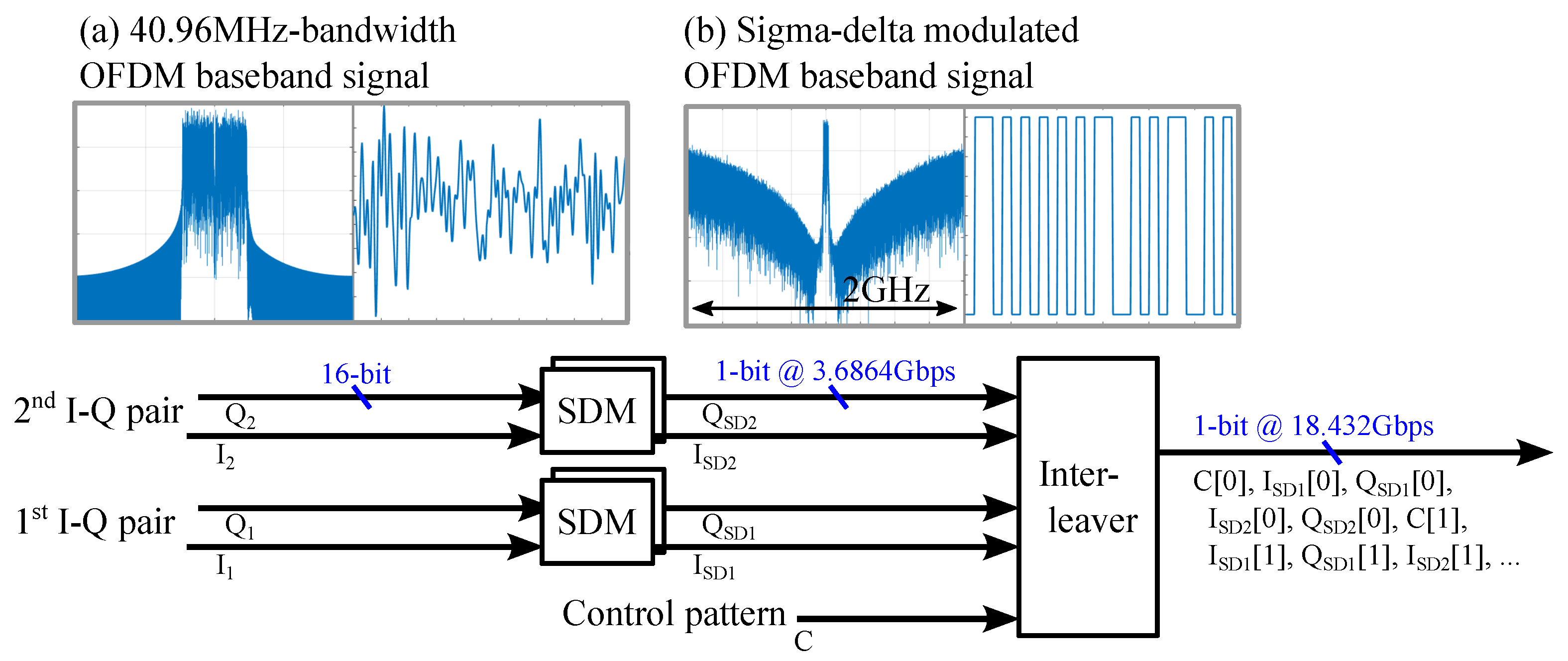
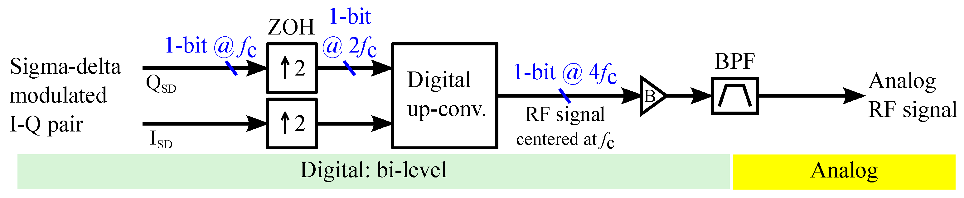
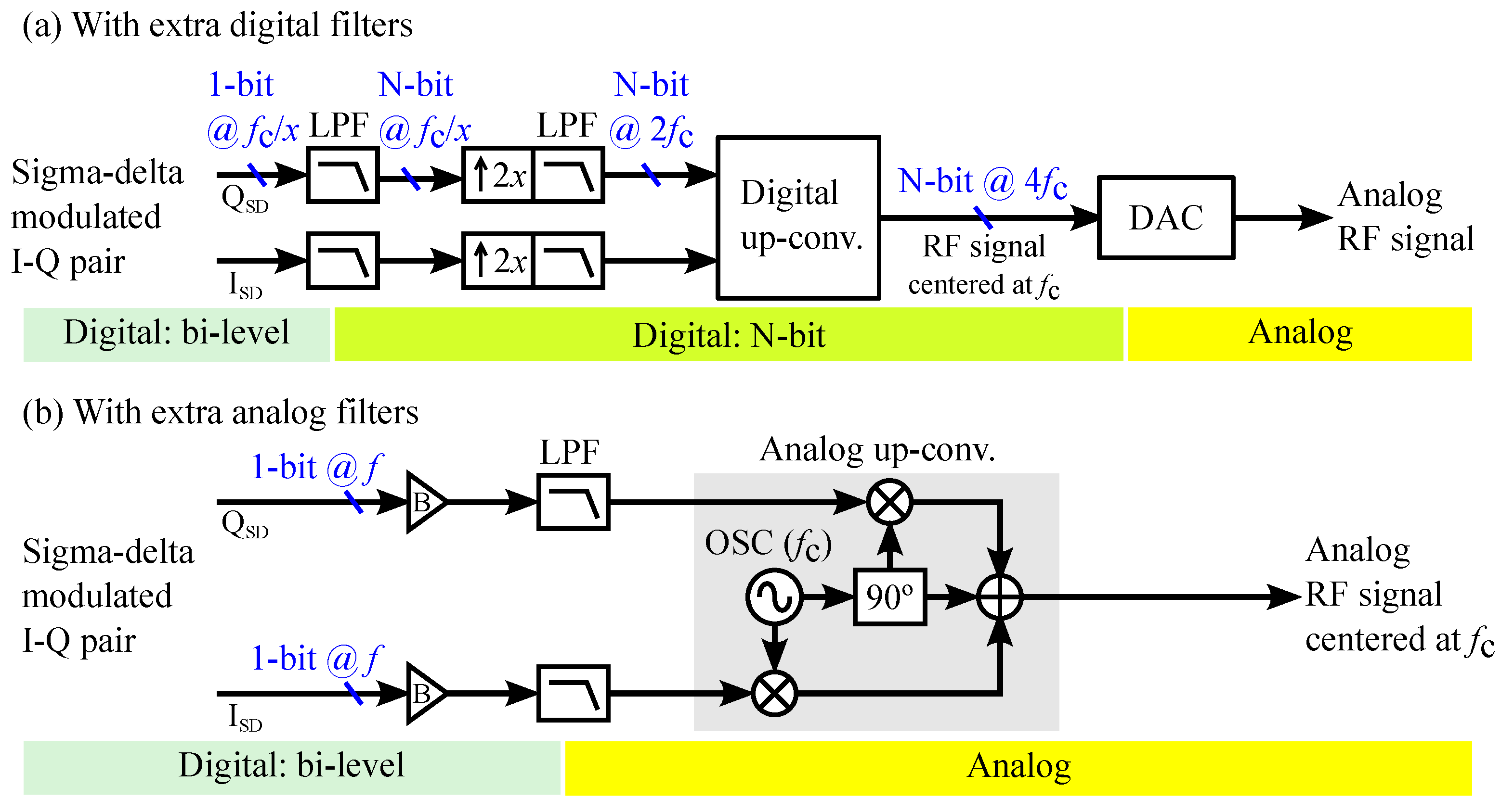
2. Bit-Interleaved Sigma-Delta-Over-Fiber (BISDoF)
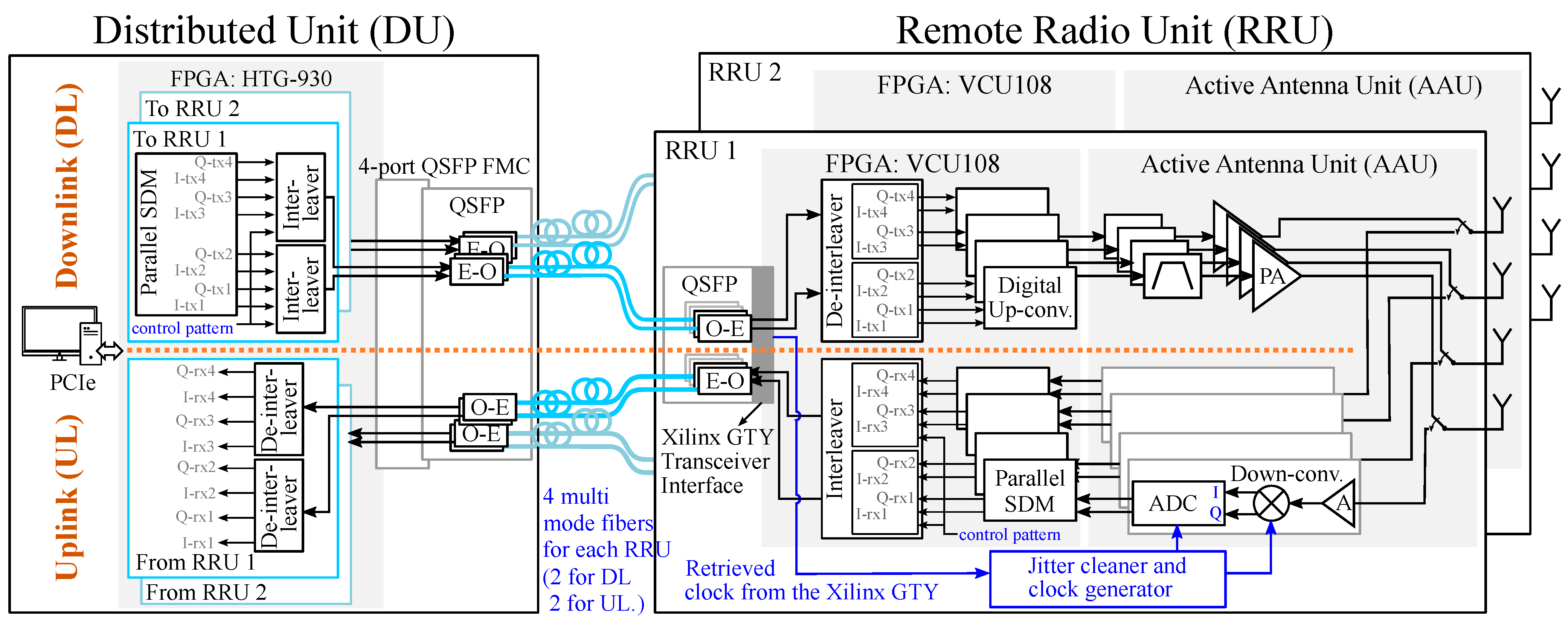
3. System Architecture
3.1. Downlink Data Path
3.2. Uplink Data Path
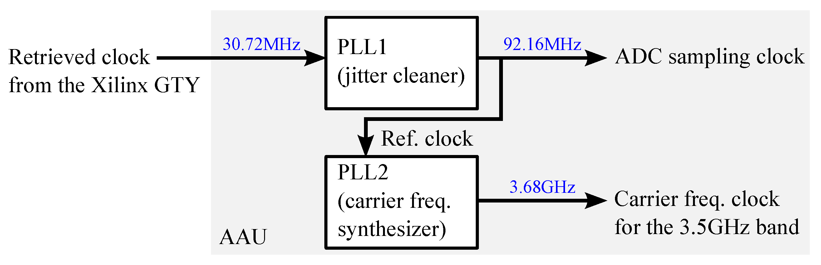
3.3. Synchronization Circuit
3.4. OFDM Signals
4. Experimental Methodology and Measurement Results
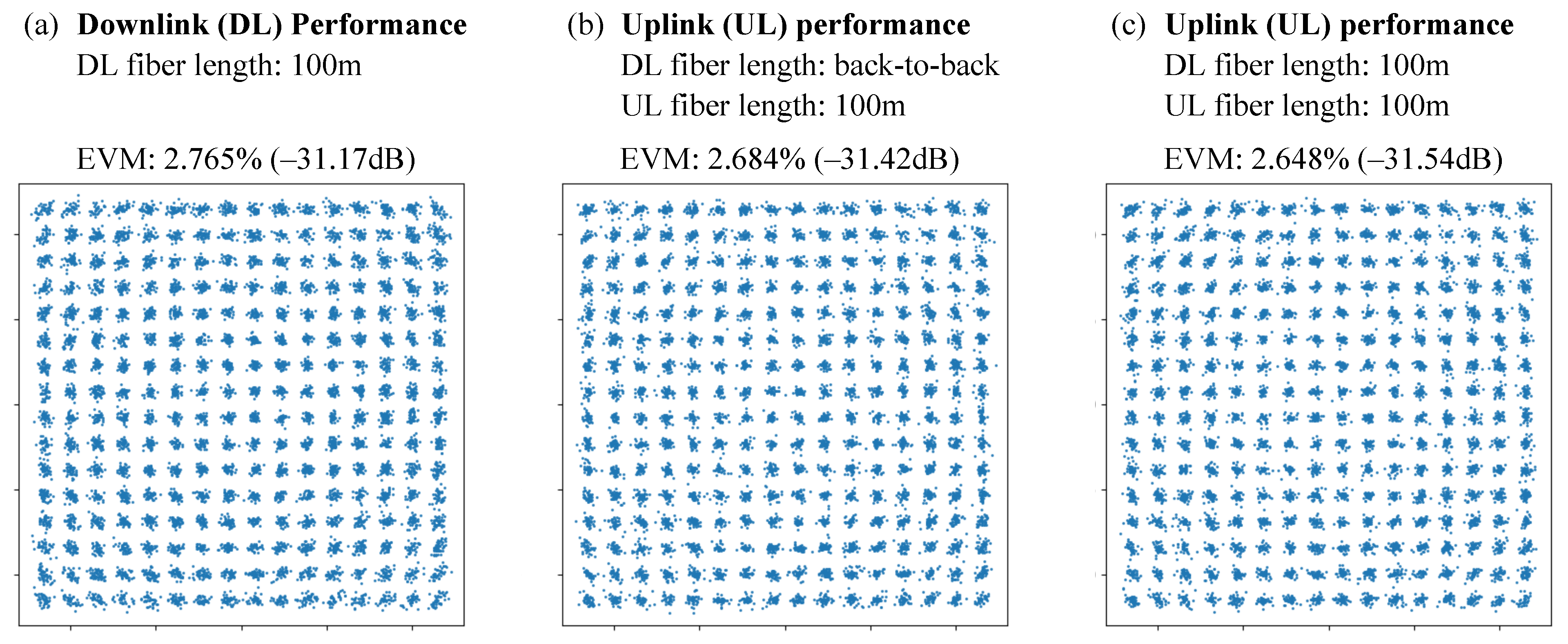
4.1. Link Performance
- 1.
- DL: from the DU to an RRU via an optical link with different fiber lengths, then from an RRU antenna to a user (electrical back-to-back);
- 2.
- UL: from a user to an RRU antenna (electrical back-to-back), then from the RRU to the DU via an optical link with different fiber lengths.
4.1.1. Downlink Performance
4.1.2. Uplink Performance
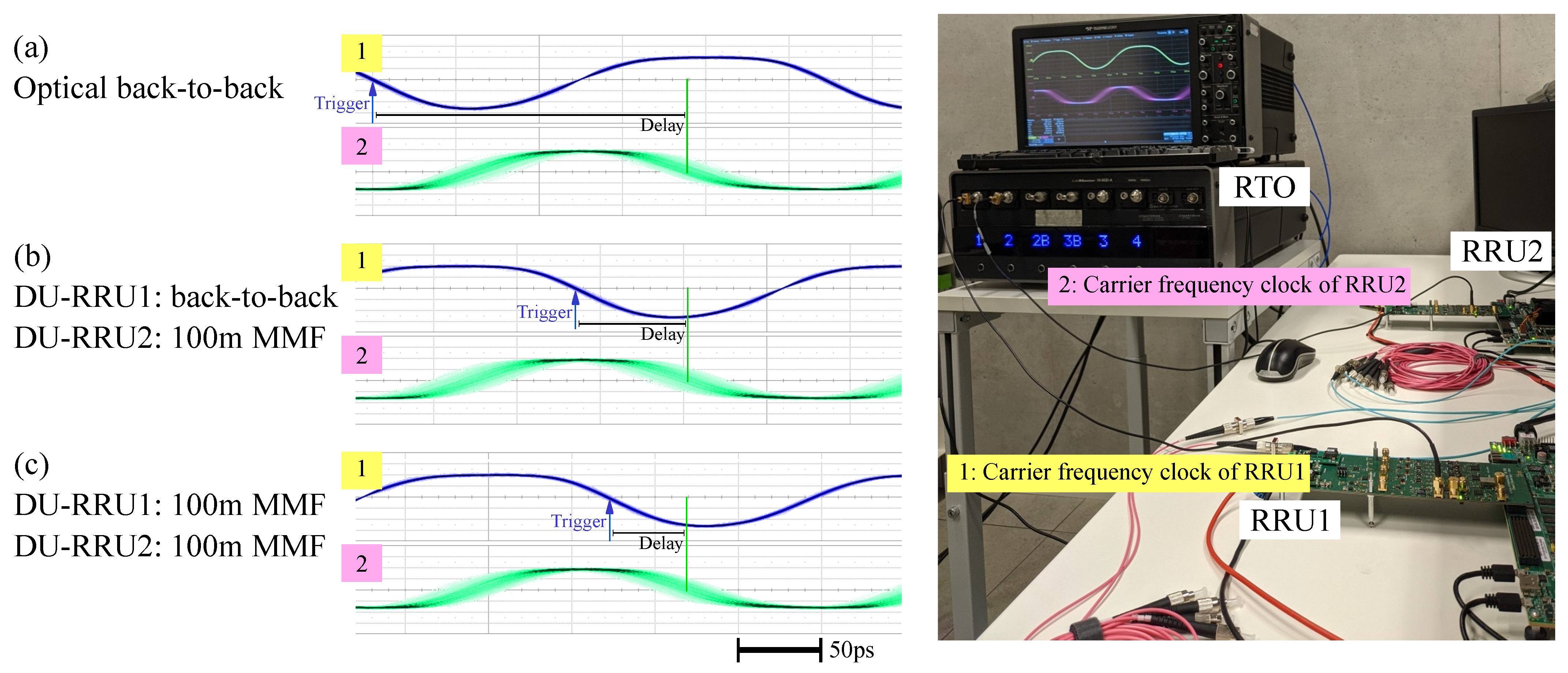
4.2. RRU Synchronism
4.2.1. Jitter Measurement
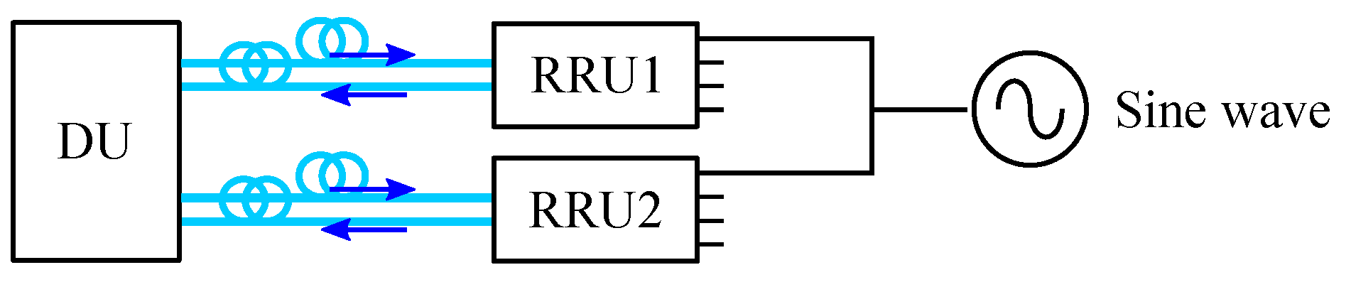
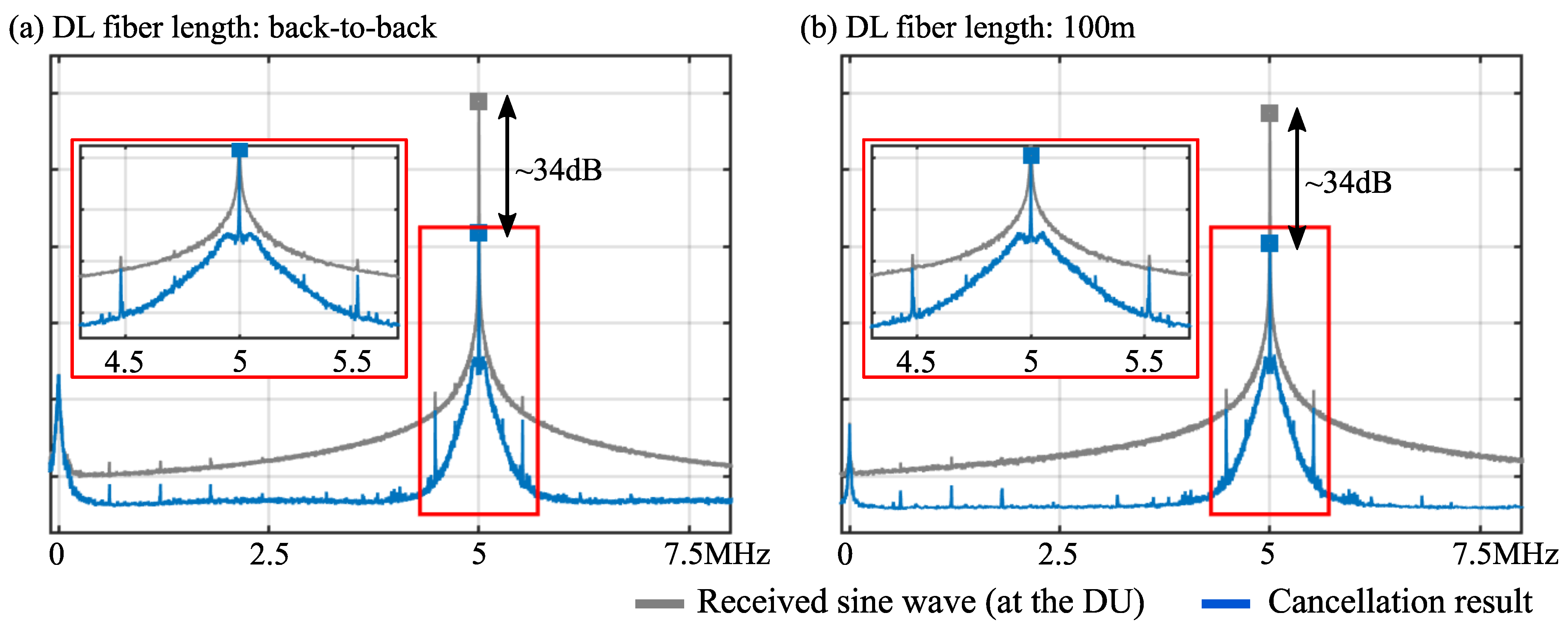
4.2.2. Spectrum Measurement
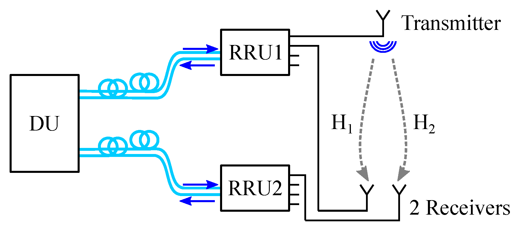
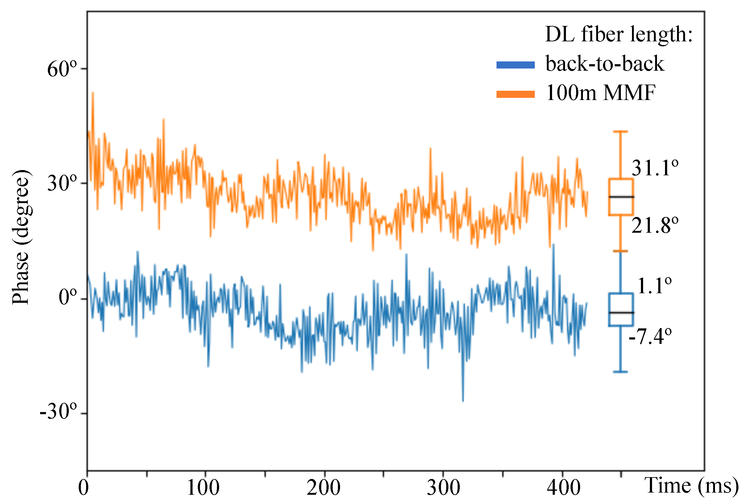
4.2.3. Phase Difference Measurement
4.3. Future Work
5. Conclusions
Author Contributions
Funding
Data Availability Statement
Acknowledgments
Conflicts of Interest
Appendix A

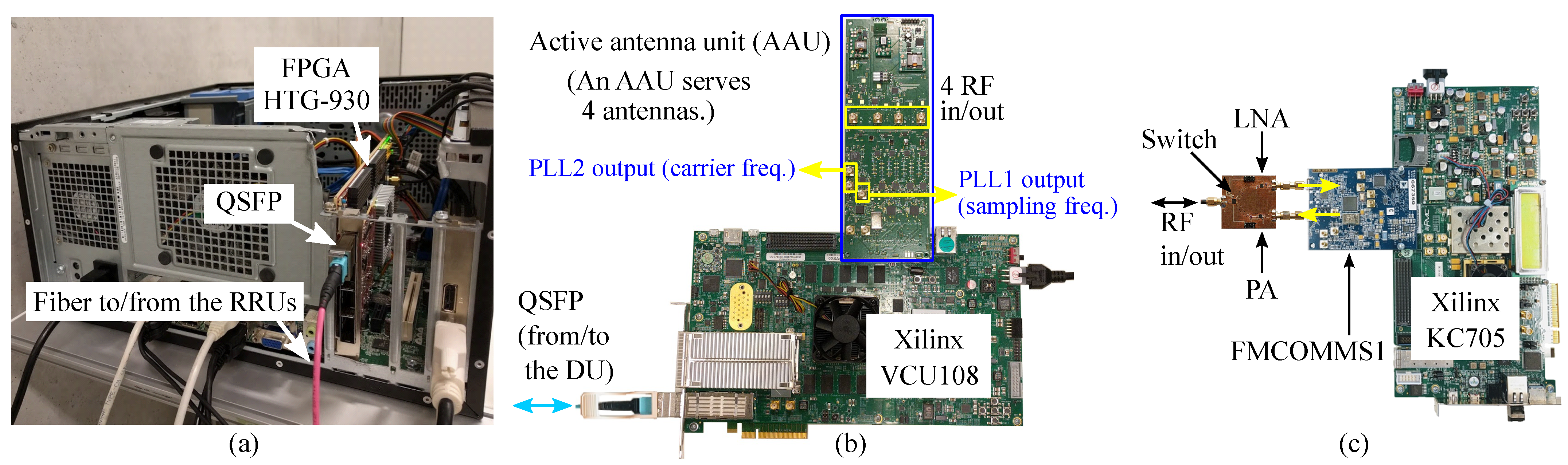
| QSFP | QSFP-100G-SR4 (850 nm) |
| Fiber | OM4 multi-mode |
| Remote radio unit (active antenna unit) | |
| switch | Analog Devices HMC8038 |
| band-pass filter | Mini-Circuits BFCV–3641+ |
| power amplifier | Analog Devices HMC327 |
| low-noise amplifier | Mini-Circuits PMA3-83LNW+ |
| down-converter | Analog Devices ADL5380 |
| analog-to-digital converter | Analog Devices AD9633 |
| crystal oscillator | Crystek CVHD–950–122.880 |
| phase lock loop (PLL) | |
| PLL1 (Figure 6) | Analog Devices AD9524 |
| PLL2 (Figure 6) | Analog Devices ADF4356 |
| User | |
| analog front-end evaluation kit | Analog Devices FMCOMMS1-EBZ |
| switch | Analog Devices HMC8038 |
| power amplifier | Analog Devices HMC327 |
| low-noise amplifier | Mini-Circuits PMA3-83LN+ |
References
- Gupta, A.; Jha, R.K. A Survey of 5G Network: Architecture and Emerging Technologies. IEEE Access 2015, 3, 1206–1232. [Google Scholar] [CrossRef]
- Akyildiz, I.F.; Kak, A.; Nie, S. 6G and Beyond: The Future of Wireless Communications Systems. IEEE Access 2020, 8, 133995–134030. [Google Scholar] [CrossRef]
- Larsson, E.G.; Edfors, O.; Tufvesson, F.; Marzetta, T.L. Massive MIMO for next generation wireless systems. IEEE Commun. Mag. 2014, 52, 186–195. [Google Scholar] [CrossRef] [Green Version]
- Ahmadi, S. 5G NR, 1st ed.; Chapter 4: New Radio Access Physical Layer Aspects (Part 2); Elsevier: Amsterdam, The Netherlands, 2019; pp. 411–654. [Google Scholar]
- Rajatheva, N.; Atzeni, I.; Bjornson, E.; Bourdoux, A.; Buzzi, S.; Dore, J.B.; Erkucuk, S.; Fuentes, M.; Guan, K.; Hu, Y.; et al. White Paper on Broadband Connectivity in 6G. 2020. Available online: https://arxiv.org/pdf/2004.14247.pdf (accessed on 28 November 2021).
- The 5G Infrastructure Public Private Partnership (5G PPP). European Vision for the 6G Network Ecosystem. 2021. Available online: https://5g-ppp.eu/wp-content/uploads/2021/06/WhitePaper-6G-Europe.pdf (accessed on 28 November 2021).
- Chen, C.; Guevara, A.P.; Pollin, S. Scaling up distributed massive MIMO: Why and How. In Proceedings of the 2017 51st Asilomar Conference on Signals, Systems, and Computers, Pacific Grove, CA, USA, 29 October–1 November 2017. [Google Scholar]
- Zhang, J.; Chen, S.; Lin, Y.; Zheng, J.; Ai, B.; Hanzo, L. Cell-Free Massive MIMO: A New Next-Generation Paradigm. IEEE Access 2019, 7, 99878–99888. [Google Scholar] [CrossRef]
- Ranaweera, C.; Wong, E.; Nirmalathas, A.; Jayasundara, C.; Lim, C. 5G C-RAN with Optical Fronthaul: An Analysis from a Deployment Perspective. J. Lightw. Technol. 2018, 36, 2059–2068. [Google Scholar] [CrossRef]
- Breyne, L.; Torfs, G.; Yin, X.; Demeester, P.; Bauwelinck, J. Comparison Between Analog Radio-over-Fiber and Sigma Delta Modulated Radio-over-Fiber. IEEE Photon. Technol. Lett. 2017, 29, 1808–1811. [Google Scholar] [CrossRef] [Green Version]
- Wang, J.; Jia, Z.; Campos, L.A.; Knittle, C.; Jia, S. Delta-Sigma Modulation for Next Generation Fronthaul Interface. J. Lightw. Technol. 2019, 37, 2838–2850. [Google Scholar] [CrossRef]
- Wu, C.-Y.; Li, H.; Caytan, O.A.E.; Van Kerrebrouck, J.; Breyne, L.; Bauwelinck, J.; Demeester, P.; Torfs, G. Distributed Multi-User MIMO Transmission Using Real-Time Sigma-Delta-over-Fiber for Next Generation Fronthaul Interface. J. Lightw. Technol. 2020, 38, 705–713. [Google Scholar] [CrossRef] [Green Version]
- Wu, C.-Y.; Li, H.; Van Kerrebrouck, J.; Vandierendonck, A.; De Paula, I.L.; Breyne, L.; Caytan, O.; Lemey, S.; Rogier, H.; Bauwelinck, J.; et al. Distributed Antenna System Using Sigma-Delta Intermediate-Frequency-over-Fiber for Frequency Bands Above 24 GHz. J. Lightw. Technol. 2020, 38, 2765–2773. [Google Scholar] [CrossRef]
- Sezgin, I.C.; Aabel, L.; Jacobsson, S.; Durisi, G.; He, Z.S.; Fager, C. All-Digital, Radio-Over-Fiber, Communication Link Architecture for Time-Division Duplex Distributed Antenna Systems. J. Lightw. Technol. 2021, 39, 2769–2779. [Google Scholar] [CrossRef]
- Wu, C.-Y.; Meysmans, C.; Li, H.; Van Kerrebrouck, J.; Caytan, O.; Lemey, S.; Bauwelinck, J.; Demeester, P.; Torfs, G. Demonstration of a scalable distributed antenna system using real-time bit-interleaved sigma-delta-over-fiber architectures. In Proceedings of the 2020 European Conference on Optical Communications (ECOC), Brussels, Belgium, 6–10 December 2020. [Google Scholar]
- Ebrahimi, M.M.; Helaoui, M.; Ghannouchi, F.M. Delta-Sigma-Based Transmitters: Advantages and Disadvantages. IEEE Microw. Mag. 2013, 14, 68–78. [Google Scholar] [CrossRef]
- Frappé, A.; Flament, A.; Stefanelli, B.; Kaiser, A.; Cathelin, A. An All-Digital RF Signal Generator Using High-Speed ΔΣ Modulators. IEEE J. Solid-State Circuits 2009, 44, 2722–2732. [Google Scholar] [CrossRef]
- Caytan, O.A.E.; Bogaert, L.; Li, H.; Van Kerrebrouck, J.; Lemey, S.; Torfs, G.; Bauwelinck, J.; Demeester, P.; Agneessens, S.; Ginste, D.V.; et al. Passive Opto-Antenna as Downlink Remote Antenna Unit for Radio Frequency Over Fiber. J. Lightw. Technol. 2018, 36, 4445–4459. [Google Scholar] [CrossRef]
- Li, H.; Breyne, L.; Van Kerrebrouck, J.; Verplaetse, M.; Wu, C.-Y.; Demeester, P.; Torfs, G. A 21-GS/s Single-Bit Second-Order Delta-Sigma Modulator for FPGAs. IEEE Trans. Circuits Syst. II Express Briefs 2019, 66, 482–486. [Google Scholar] [CrossRef] [Green Version]
- IEEE Computer Society LAN/MAN Standards Committee. IEEE Standard for information technology—Telecommunications and information exchange between systems Local and metropolitan area networks—Specific requirements—Part 11: Wireless LAN Medium Access Control (MAC) and Physical Layer (PHY) Specifications—Amendment 4: Enhancements for Very High Throughput for Operation in Bands below 6 GHz. IEEE Std 802.11. 2013, pp. 1–425. Available online: https://0-ieeexplore-ieee-org.brum.beds.ac.uk/servlet/opac?punumber=6687185 (accessed on 28 November 2021).
- 3GPP TS 38.104. New Radio (NR): Base Station (BS) Radio Transmission and Reception (Release 17) (V17.3.0); September 2021. Available online: https://www.tech-invite.com/3m38/tinv-3gpp-38-104.html (accessed on 28 November 2021).
- Mody, A.N.; Stüber, G.L. Synchronization for MIMO OFDM Systems. In Proceedings of the GLOBECOM, San Antonio, TX, USA, 25–29 November 2001. [Google Scholar]
- Sezgin, I.C.; Gustavsson, J.; Lengyel, T.; Eriksson, T.; He, Z.S.; Fager, C. Effect of VCSEL Characteristics on Ultra-High Speed Sigma-Delta-Over-Fiber Communication Links. J. Lightw. Technol. 2019, 37, 2109–2119. [Google Scholar] [CrossRef]
- Common Public Radio Interface (CPRI) Specification V7.0. 2015. Available online: http://www.cpri.info/spec.html (accessed on 28 November 2021).
- Van De Beek, J.J.; Edfors, O.; Sandell, M.; Wilson, S.K.; Borjesson, P.O. On Channel Estimation in OFDM Systems. In Proceedings of the 1995 IEEE 45th Vehicular Technology Conference. Countdown to the Wireless Twenty-First Century, Chicago, IL, USA, 25–28 July 1995. [Google Scholar]


| Data bandwidth | 40.96 MHz |
| Subcarrier spacing | 320 KHz |
| 128 subcarriers (index: −64 to 63) | |
| Pilot subcarrier indices | ±11, ±25, ±33 |
| DC subcarrier indices | ±1, 0 |
| Null subcarrier indices | −64 to −59, 59 to 63 |
| Number of data subcarriers | 108 |
| Cyclic prefix (CP) size | 1/4 (0.78 us) |
| Modulation scheme | 256-QAM (quadrature amplitude modulation) |
| DL (DU to RRU) Fiber Length | |||
|---|---|---|---|
| Back-to-Back | 30 m MMF | 100 m MMF | |
| EVM | 2.725% (−31.29 dB) | 2.752% (−31.21 dB) | 2.765% (−31.17 dB) Constellation: Figure 7a. |
Publisher’s Note: MDPI stays neutral with regard to jurisdictional claims in published maps and institutional affiliations. |
© 2021 by the authors. Licensee MDPI, Basel, Switzerland. This article is an open access article distributed under the terms and conditions of the Creative Commons Attribution (CC BY) license (https://creativecommons.org/licenses/by/4.0/).
Share and Cite
Wu, C.-Y.; Li, H.; Van Kerrebrouck, J.; Meysmans, C.; Demeester, P.; Torfs, G. A Bit-Interleaved Sigma-Delta-Over-Fiber Fronthaul Network for Frequency-Synchronous Distributed Antenna Systems. Appl. Sci. 2021, 11, 11471. https://0-doi-org.brum.beds.ac.uk/10.3390/app112311471
Wu C-Y, Li H, Van Kerrebrouck J, Meysmans C, Demeester P, Torfs G. A Bit-Interleaved Sigma-Delta-Over-Fiber Fronthaul Network for Frequency-Synchronous Distributed Antenna Systems. Applied Sciences. 2021; 11(23):11471. https://0-doi-org.brum.beds.ac.uk/10.3390/app112311471
Chicago/Turabian StyleWu, Chia-Yi, Haolin Li, Joris Van Kerrebrouck, Caro Meysmans, Piet Demeester, and Guy Torfs. 2021. "A Bit-Interleaved Sigma-Delta-Over-Fiber Fronthaul Network for Frequency-Synchronous Distributed Antenna Systems" Applied Sciences 11, no. 23: 11471. https://0-doi-org.brum.beds.ac.uk/10.3390/app112311471