
A Supervised Neural Network Control for Magnetorheological Damper in an Aircraft Landing Gear


School of Aerospace and Mechanical Engineering, Korea Aerospace University, Goyang-si 10540, Gyeonggi-do, Korea
*
Author to whom correspondence should be addressed.
Appl. Sci. 2022, 12(1), 400; https://0-doi-org.brum.beds.ac.uk/10.3390/app12010400
Submission received: 9 December 2021
/
Revised: 25 December 2021
/
Accepted: 29 December 2021
/
Published: 31 December 2021
(This article belongs to the Special Issue Structural Vibration: Analysis, Control, Experiment, and Applications II)
Abstract
:This paper adopts an intelligent controller based on supervised neural network control for a magnetorheological (MR) damper in an aircraft landing gear. An MR damper is a device capable of adjusting the damping force by changing the magnetic field generated in electric coils. Applying an MR damper to the landing gears of an aircraft could minimize the impact at landing and increase the impact absorption efficiency. Various techniques proposed for controlling the MR damper in aircraft landing gears require information on the damper force or the mass of the aircraft to determine optimal parameters and control commands. This information is obtained by estimation with a model in a practical operating environment, and the accompanying inaccuracies cause performance degradation. Machine learning-based controllers have also been proposed to address model dependency but require a large number of drop test data. Unlike simulations, which can conduct a large number of virtual drop tests, the cost and time are limited in the actual experimental environment. Therefore, a neural network controller with supervised learning is proposed in this paper to simulate the behavior of a proven controller only with system states. The experimental data generated by applying the hybrid controller with the exact mass and force information, which has demonstrated high performance among the existing techniques, are set as the target for supervised learning. To verify the effectiveness of the proposed controller, drop test experiments using the intelligent controller and the hybrid controller with and without exact information about aircraft mass and force are executed. The experimental results from the drop tests of a landing gear show that the proposed controller maintains superior performance to the hybrid controller without using explicit damper models or any information on the aircraft mass or strut force.
1. Introduction
Aircraft landing gears are critical elements that effectively mitigate and absorb vibrations and shocks during the takeoff and landing process to support the safe operation of the aircraft. Therefore, the landing gears must maintain their performance in various landing situations. The damper is the heart of the landing gear, which is the central part responsible for absorbing and dissipating kinetic energy during the touchdown and taxing phases. However, oleo-pneumatic dampers, the most commonly used passive devices, are designed only at a critical case following FAR Part 25 [1]. Thus, the passive dampers are limited in improving the landing performance in different landing cases. Magnetorheological (MR) dampers have received significant attention to replace these passive dampers. The MR damper has many applications, such as suppressing chatter conditions during the milling operations of thin-floor components [2], changing the structural behavior of buildings during earthquakes [3], and reducing vibrations in gun recoil control [4]. An MR damper is a semi-active device that adjusts the damping force due to the fluid inside the damper by changing the magnetic field formed in the coil around the orifice. Thus, for the effective use of the MR damper, a controller is designed to produce an appropriate electrical current, which generates the desired damping force [5].
Thus far, many control algorithms for MR damper landing gears have been developed and applied through drop test simulations or experiments. For example, Grzegorz Mikulowski and Lukasz Jankowski developed an adaptive control to mitigate the peak force transferred to the aircraft structure during touchdown [6]. Young-Tai Choi and et al. designed and analyzed an MR landing gear system for a helicopter and then developed feedback control algorithms to apply a constant damping force over the desired sink speed range [7]. X. M. Dong and G. W. Xiong invested in an intelligent control algorithm based on a human-simulated control to reduce the peak impact load of sprung mass within the stroke of a damper [8]. Young-Tai Choi and Norman M. Wereley applied a sliding mode control to reduce the vibration during touchdown [9]. The controllers in the previous studies require measurements or estimates of the strut force of a damper, i.e., the internal reaction between the cylinder and piston of the damper. It is not possible in operating aircraft landing gears to measure the strut force directly due to its nature. The strut force can be indirectly measured and estimated with multiple sensors and mathematical models, increasing the system complexity and cost. Moreover, in the estimation models and controllers, the aircraft mass is assumed to be known, of which the accuracy is, however, limited. Thus, the controllers underdeliver due to the inaccurate information on the aircraft mass and strut force in certain practical operations of the dampers. This problem also occurs in force control [10] and hybrid control [11] developed in previous studies by the authors.
Machine learning is a subset of artificial intelligence [12] that has proven its ability to improve the adaptiveness of autonomous systems, such as self-driving cars [13] and robotics [14], without exact prior knowledge of the systems and operating environment. Qiang Xu and et al. [15] developed a back-propagation artificial neural network, which is optimized by an artificial bee colony algorithm based on the control force calculated by a linear quadratic regulator. Luong and et al. [16] applied an intelligent controller based on a neural network to improve the landing performance in different landing cases. The neural network is trained by using a genetic algorithm and policy gradient estimation. If a neural net with system state variables as its inputs is used to generate a control command, a controller could be designed to adaptively operate in differing landing situations without parameter estimates or models. However, existing techniques using neural nets use optimization or reinforcement learning schemes, so a large amount of data is required for sufficient learning. A sufficient amount of data can be given in a numerical simulation environment, and thus a neural net controller shows good performance. On the other hand, sufficient learning could be challenging to achieve with actual drop test experiments because only a limited number of drop tests are performed due to cost and time limitations. Neural nets that are not sufficiently learned not only degrade the performance but can also cause unpredictable behavior. A supervised learning approach with a proven controller as a target can be a solution to this problem. This enables a controller to show adaptability in various landing conditions without relying on models and parameter estimations, with a relatively small number of experiments.
This paper presents an intelligent controller based on supervised learning for a landing gear equipped with an MR damper adaptively operating in various landing conditions, without any online knowledge or estimates of mass and forces. To this end, the hybrid control is applied to the MR damper in a drop test environment with a dSPACE platform for generating training data for a neural network controller. The hybrid control [11,17] utilizes exact values of test mass and data from a load cell for measuring the ground reaction force, which is, of course, ideal because it is not possible in the actual operating environment of aircraft landing gears. The hybrid controller is also well tuned for each landing condition to maintain high landing performance. The inputs of the neural net are the state variables of the damper, and thus the presented controller trained with the hybrid control in the ideal environment is also applicable in landing conditions other than where it is trained. Comparative experiments are conducted to verify the effectiveness of the presented intelligent controller against a passive damper and existing controllers, i.e., skyhook controller and hybrid controller in differing landing conditions of aircraft mass and sink speeds. In the comparative experiments, the skyhook and hybrid controllers use the estimates of aircraft mass and strut force with a mathematical model for emulating a realistic operating environment.
The structure of the paper is as follows: Section 2 describes the environment of the drop test experiments for an MR damper landing gear; Section 3 explains the performance measure of the drop tests; Section 4 details the principles and experimental results of the hybrid controller; Section 5 describes the structure and training of the neural network controller; Section 6 presents the comparative experimental results; the conclusions are presented in Section 7.
2. Drop Test Environment of MR Damper Landing Gear
The most common way to evaluate the performance of landing gears is to perform drop tests. When an aircraft touches down on the ground, a large amount of kinetic energy due to the aircraft’s descent speed must be effectively dissipated through the landing gears. At this moment, the damper of a landing gear reciprocates several times after being compressed in a very short time, and thus a significant impact is transmitted to the aircraft structure above the landing gear. Therefore, for the aircraft’s structural safety and passengers’ convenience, the damper must be designed and controlled so that the strut force and stroke, i.e., the compression distance of the damper’s piston, appear at appropriate levels.
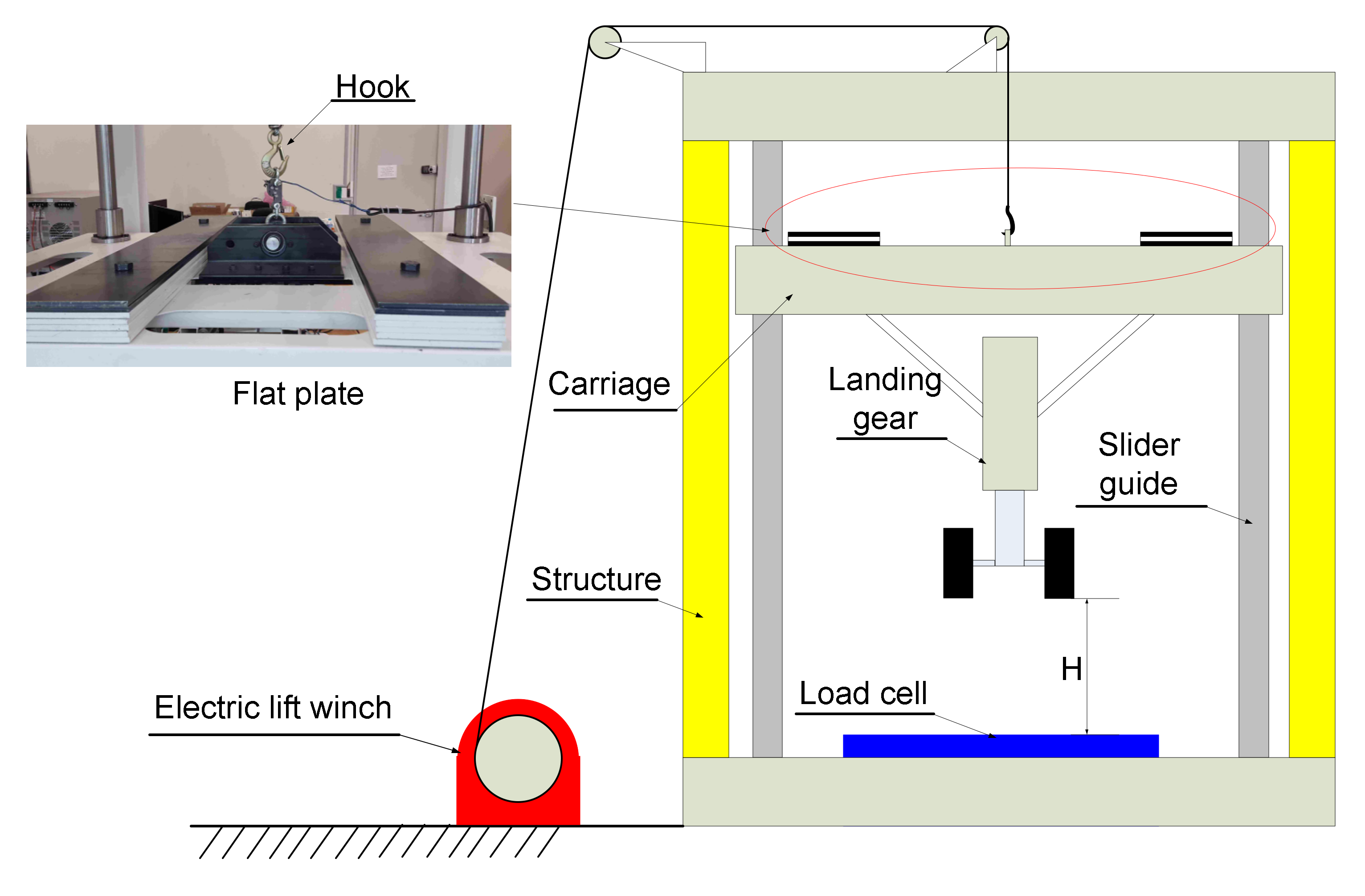
Figure 1 shows a schematic diagram of the drop test environment for the MR damper landing used in this study. The landing gear is fixed solidly to a carriage that can move smoothly in the vertical direction by four slider guides. The carriage is lifted by using an electric lift winch. The electric lift winch pulls the cable that connects with the carriage by a hook. When the carriage is released out of the hook, the landing gear falls down to the bottom, where a load cell sensor is installed to measure the ground reaction force of the landing gear. The mass of the aircraft that the landing gear supports can be simulated and adjusted by changing the weight of the flat plates placed on the carriage. The sink speed , i.e., the descent speed of the aircraft at touchdown, can also be changed by adjusting the height at which the landing gear is released from the bottom.
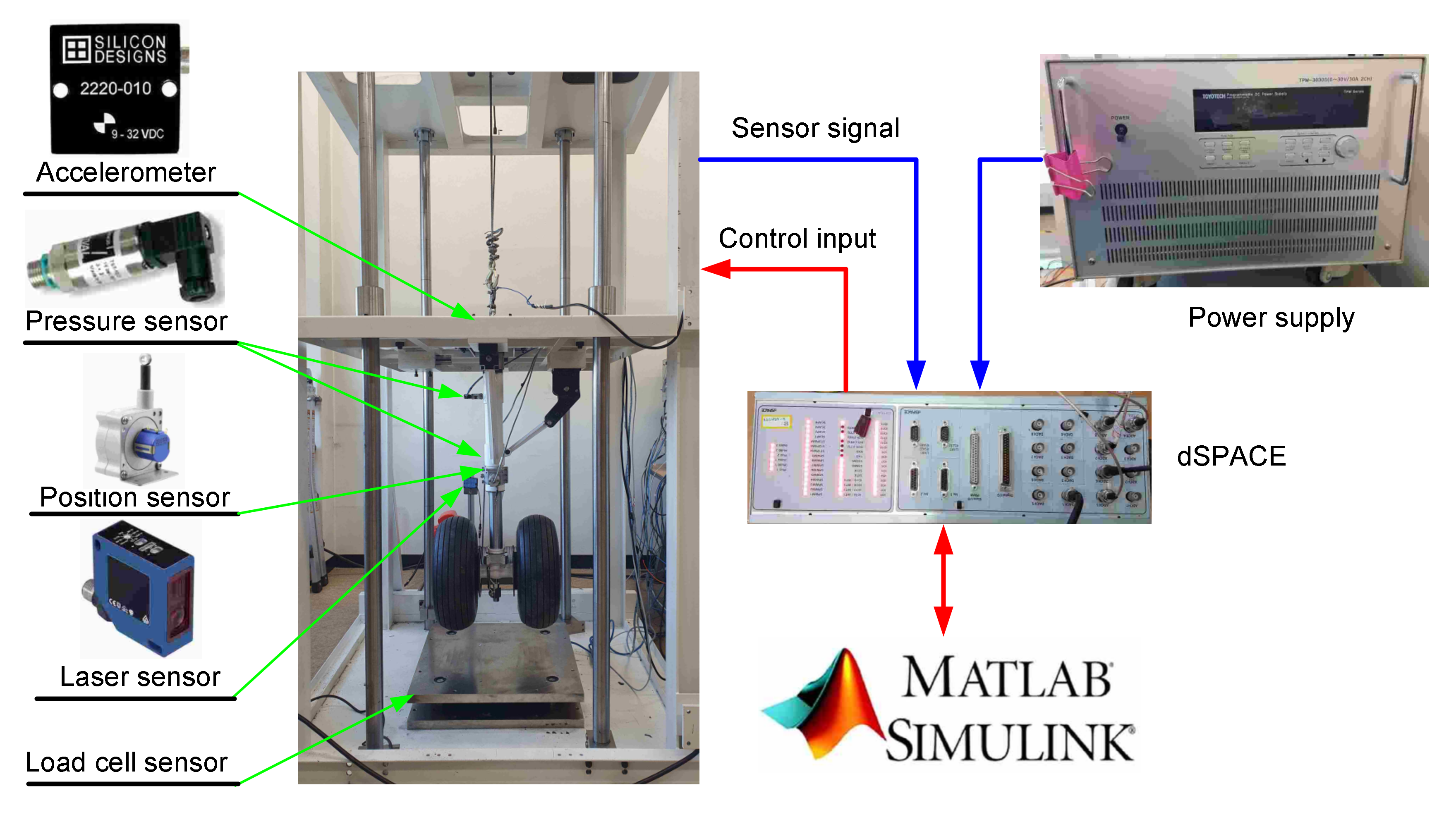
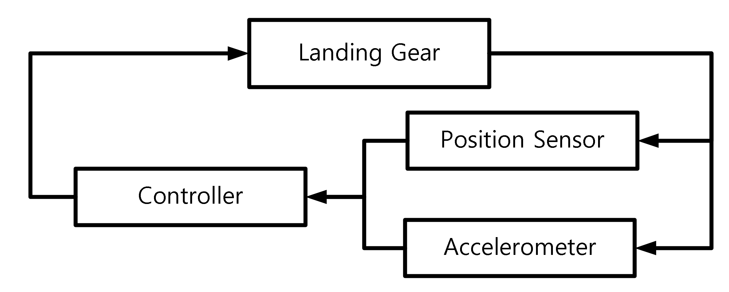
Figure 2 shows the details of the sensors and signal processing components of the drop test environment. The drop test environment has six sensors for monitoring the state variables and for computing control commands: a load cell measuring the ground reaction force, a laser sensor for the displacement of the sprung mass (including the plate weights, carriage, and damper cylinder), a position sensor for the stroke of the damper, two pressure sensors for the damper’s upper and lower oil chambers, and an accelerometer for measuring the vertical acceleration of the sprung mass. Since the stroke is the compression distance of the damper’s piston, it can be expressed as the difference between the sprung mass displacement and unsprung mass (including piston and tire) displacement , and the can be computed from the sensors for and . The data acquisition is achieved via a dSPACE mini box that connects to a host PC running MATLAB Simulink. The controllers for the MR damper are developed in Simulink models to claim the control signal, which then provides the electrical current to the MR damper’s coil.
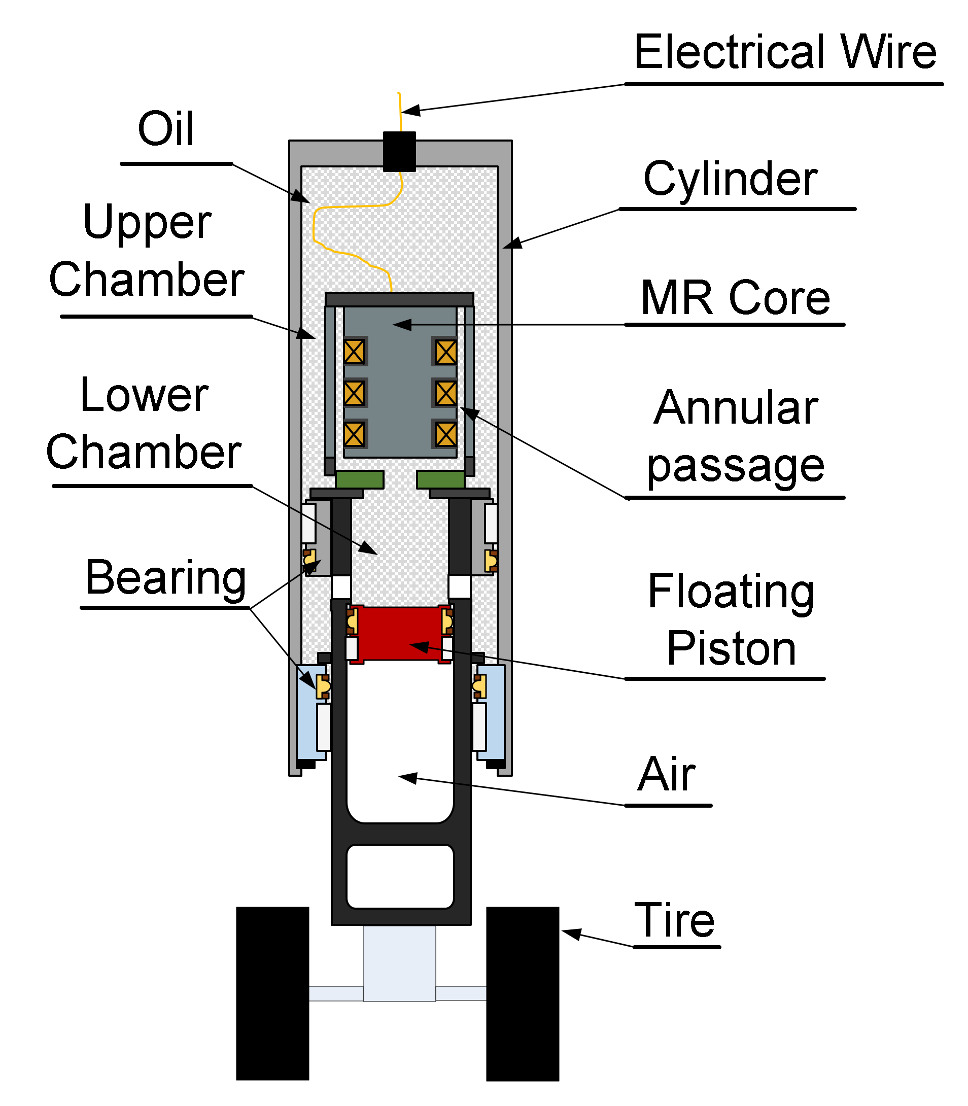
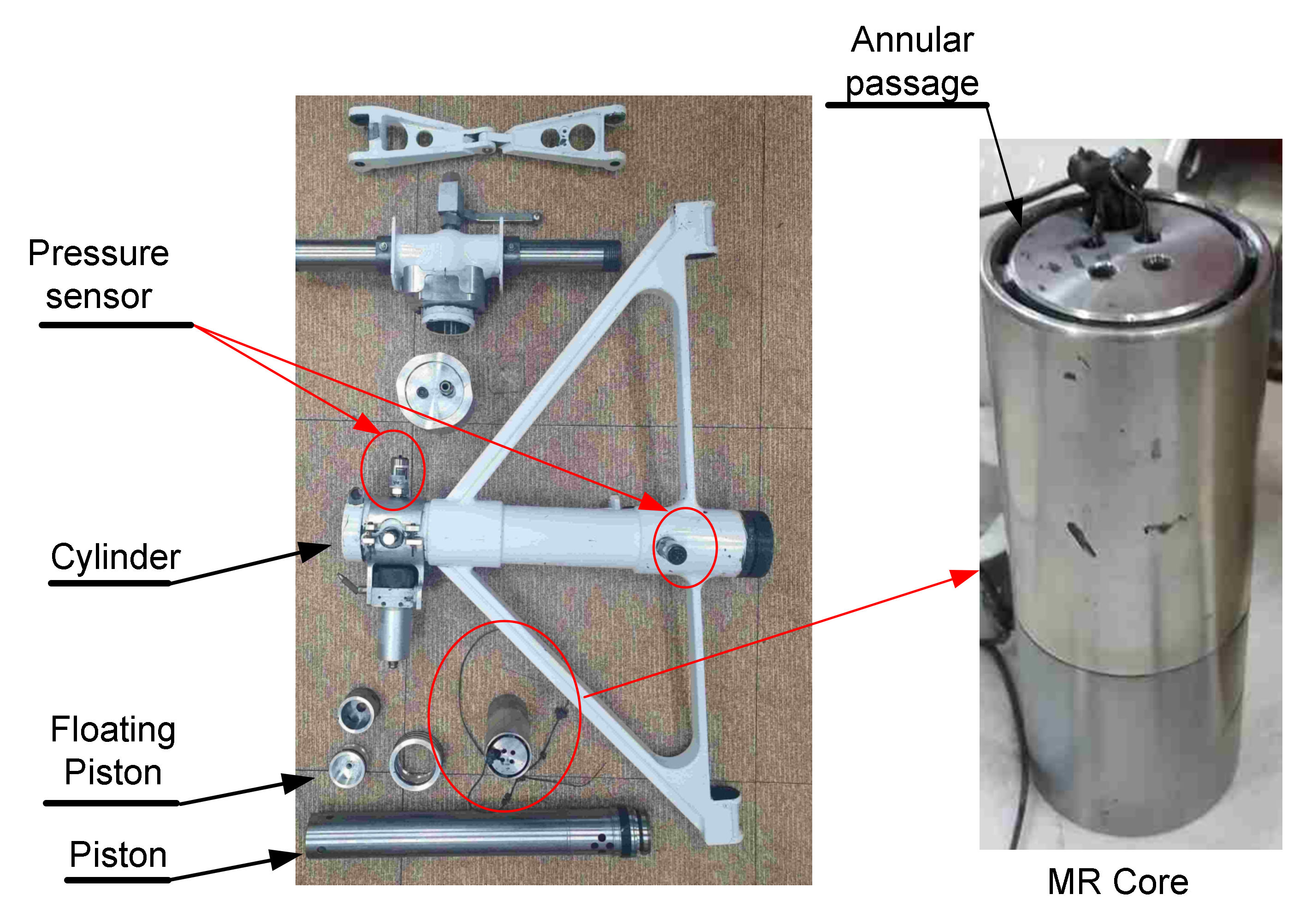
Figure 3 shows the structure of the landing gear equipped with the MR damper in this work. The MR damper consists of a piston connecting to a wheel assembly and a cylinder fixed to the carriage. Two wheels are set up symmetrically to the landing gear to reduce the impact of the friction force on the bearings. The internal spaces of the cylinder and piston, named the upper and lower chambers, are filled with MR fluid (LORD MRF-140CG), which changes its microscopic property subject to a magnetic field. The LORD MRF-140CG has many features and benefits that are suitable for landing gear, such as fast response time, dynamic yield strength, temperature resistance, hard settling resistance, and non-abrasiveness [18]. The cylinder has an MR core at its top. The core has multiple coils placed near the annular passage (Figure 4), where the major portion of the damping force is generated. As the damper is compressed or stretched, the cylinder rises or falls, and a flow toward the lower chamber or the upper chamber is formed through the annular passage. The viscosity of the fluid flowing through the narrow passage creates a damping force as in traditional pneumatic dampers, and, by applying a current to the coils, the resulting magnetic field forms the yield stress from the MR fluid, which causes a controllable damping force in the opposite direction of the damper’s motion.
In the piston, a floating piston separates the lower chamber and air chamber, filled with pressured air to provide a spring-like force according to the damper stroke. Due to the incompressibility of the MR fluid, the location of the floating piston and the air chamber pressure is solely determined by the stroke position of the damper. The pressure levels of the lower chamber and the air chamber are equalized with the minimal weight of the floating piston, and the air chamber stores the un-dissipated redundant energy during the compression phase and releases this energy during the next extension phase.
3. Performance Measure of Aircraft Landing Gear in Drop Tests
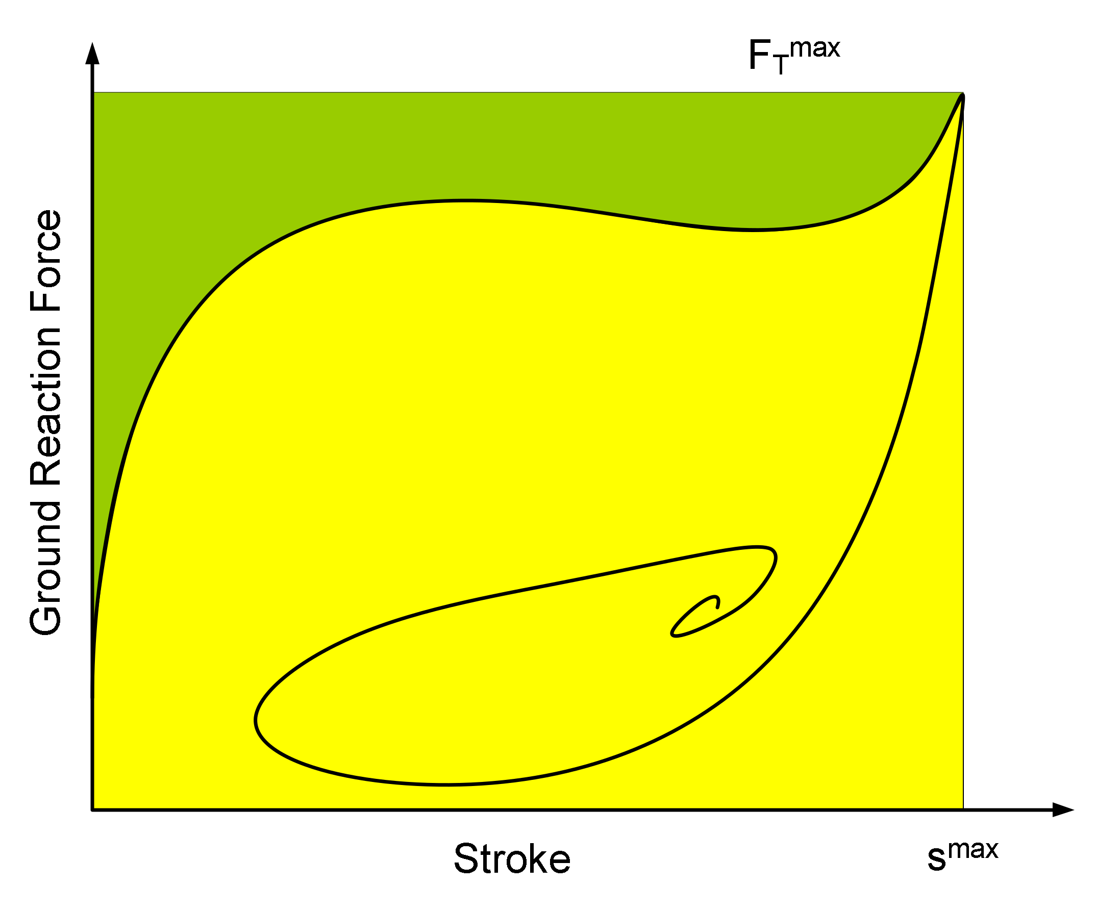
As mentioned in the previous section, the damper of an aircraft landing gear must effectively absorb the kinetic energy of the aircraft in order to minimize the impact and vibration caused at the moment of landing. Accordingly, it is necessary to reduce the stroke of the damper and the strut force transmitted to the aircraft fuselage through the damper. The strut force is composed of the damping force, the spring force from the air chamber, and the friction at the bearings. It is important to measure the elements of the strut force without a significant increase in cost and complexity. Therefore, the ground reaction force is generally utilized in performance measures for aircraft landing gear tests. The most commonly used performance measure to quantify the effectiveness of energy absorption of the damper is shock absorber efficiency [11,19]. The shock absorber efficiency is defined by the ratio between the energy absorbed by the damper during the first stroke and the product of maximum ground reaction force and maximum stroke [11].
Figure 5 shows a force–stroke curve, called the efficiency curve, of a typical single landing gear. The efficiency curve is the trajectory of the force–stroke pair of the damper’s behavior during landing, and visualizes the implication of the energy absorption efficiency: the ratio between the area below the curve in and the square area of . Therefore, the closer to the square the curve is, the higher the efficiency is. Observe that the typical efficiency curve has two peaks at the first compression phase, where the stroke translates from 0 to . The first peak occurs when the stroke velocity reaches its maximum value because the nonlinear spring force from the air chamber is relatively small compared to the damping force proportional to the velocity. The second peak appears when the stroke reaches , where the spring force dominates the strut force. Since and are reached in the first compression phase, the shock absorber efficiency is determined by the shape of the efficiency curve in this phase. Therefore, if the heights of the two peaks are adjusted to be the same, and the dent between them is filled with a controllable MR damping force, the efficiency could be significantly improved. During touchdown, two main parameters, which are aircraft mass () and sink speed (v), have a huge impact on the potential and kinetic energy of the aircraft [19]. Thus, only aircraft mass and sink speed are considered in this research. According to the conditions of our experiment, the ranges of aircraft mass and sink speeds are given by:
4. Hybrid Controller with Load Cell Data and Known Aircraft Mass
4.1. Control Principle
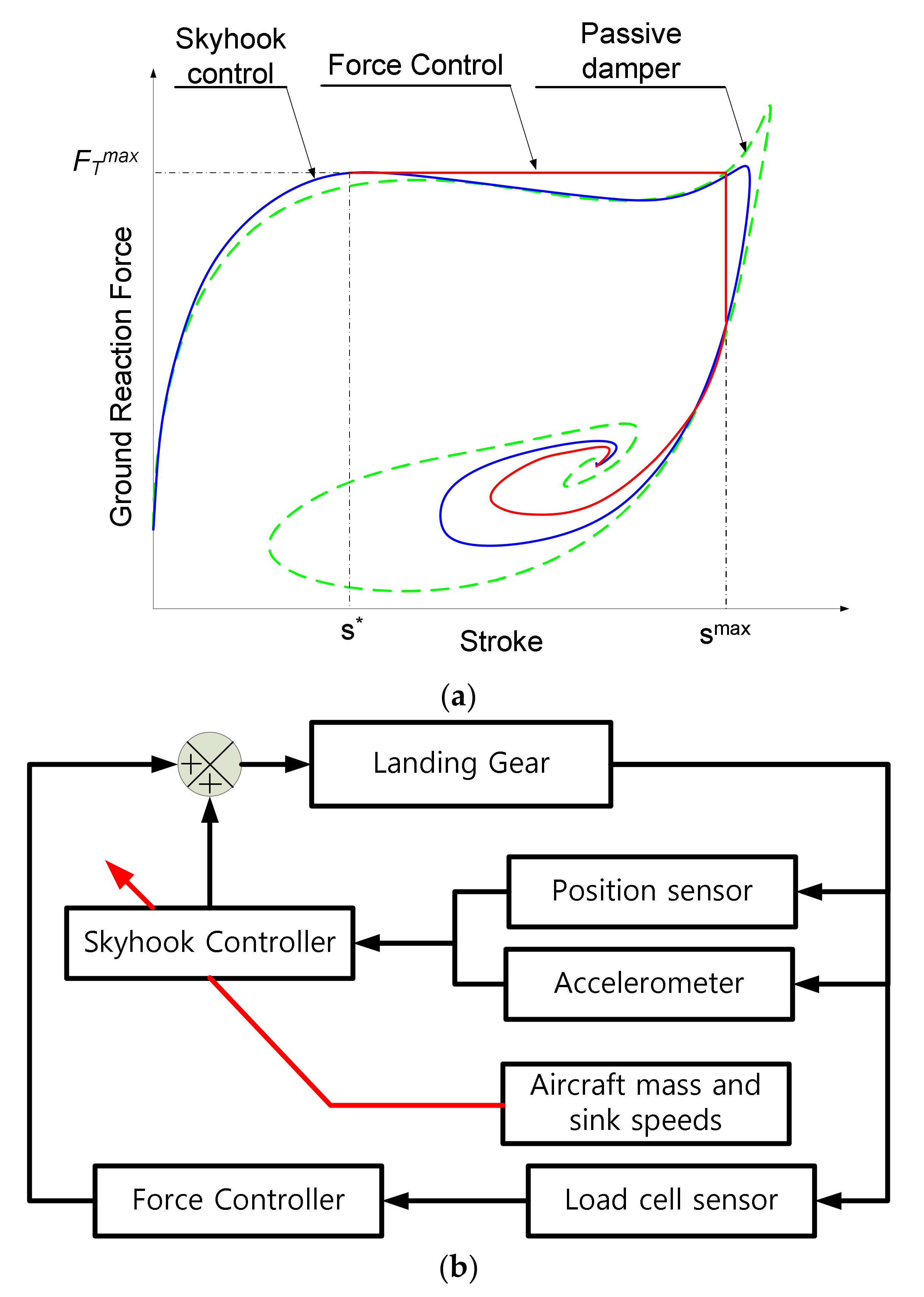
Figure 6 shows the principal concept of the hybrid controller with load cell data for measuring and exact mass information. It can be seen that the hybrid controller is the combination of the skyhook controller and force controller [11]. The skyhook controller [20] is designed to achieve the maximum damping force at the point where the stroke velocity reaches the maximum value (the first peak at * in Figure 6a). The force controller [10] is used to maintain the maximum damping force as far as possible during the first compression phase to fill the dent between the two peaks. Thus, the hybrid controller input () is given by:
where is the skyhook control input, and is the force control input.
The main idea of the skyhook control is to generate a damping force linear to the unsprung mass velocity. The control input of the skyhook controller is given by [21,22]:
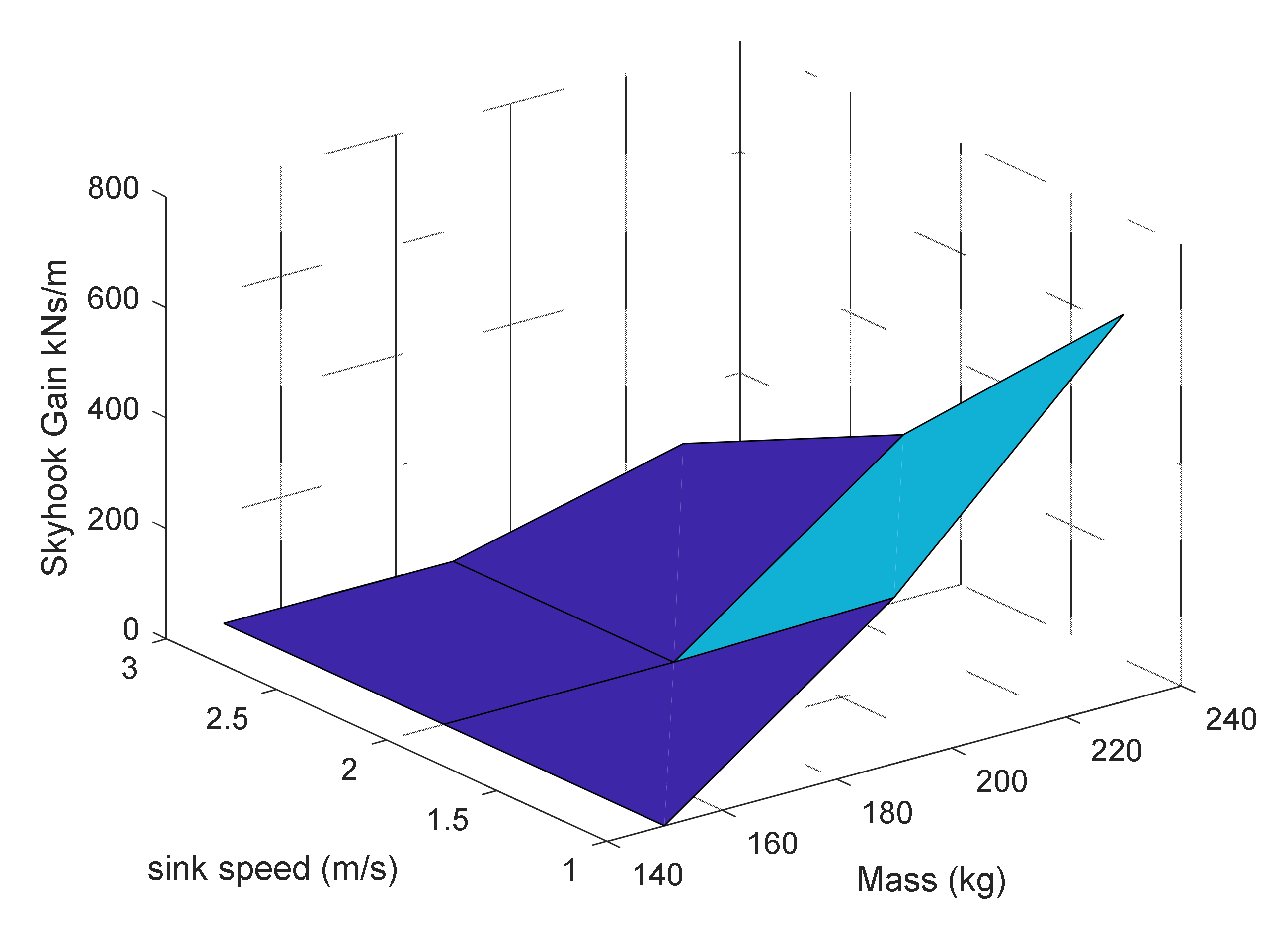
where is the vertical velocity of the sprung mass; is the stroke velocity; is called the skyhook gain. The skyhook gain is selected so that the resultant efficiency curve has the same level of peaks. The optimal gain is searched by testing the controller with the numerical simulation model of the damper for each landing condition composed of different aircraft masses and sink speeds (refer to Figure 7).
The force controller is used to maintain the force level that is attained at the first peak. The controllable MR damping force is generated to compensate for the difference between the measured ground reaction force from the load cell and desired force . The damping force applies to only the opposite direction of the damper’s motion, and thus the force control input can be given by:
4.2. Experimental Results
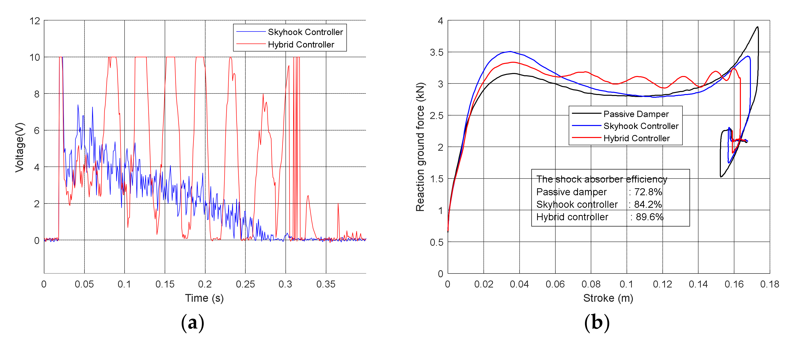
In order to confirm the performance of the hybrid controller, drop test experiments were executed with various aircraft mass and sink speeds. Figure 8 shows the comparison results of the passive damper, skyhook controller, and hybrid controller from experiments in the case of = 190 kg and = 1 m/s. The hybrid controller attempted to maintain the maximum force after the first peak for as long as possible during the first compression, bringing the curve closer to a square than other ones. However, the hybrid controller could not completely compensate for the force error, mainly due to the response time of the MR core and the limit of the applied voltage for system safety.
However, the hybrid controller still exhibited the highest shock absorber efficiency compared with the passive damper and skyhook controller. Table 1 presents the comparison results of the passive damper, skyhook controller, and hybrid controller for differing aircraft masses and sink speeds. It can be seen that the hybrid controller produced better landing gear performance than others. The hybrid controller exhibited the highest shock absorber efficiency in all test conditions and showed the smallest stroke and the smallest maximum ground reaction force in most of the conditions.
4.3. Control Scheme in Practical Operation Environment
In practical operating environments of landing gears equipped with MR dampers, the mass information of the aircraft supported by each landing gear may not be accurate, and the ground reaction force or strut force cannot be measured, so MR damper controllers must be driven with estimates based on mathematical models. It is assumed that the sensors that the controllers can use are limited to an accelerometer generally installed in the aircraft and a position sensor that measures the stroke of the landing gear to avoid an unnecessary increase in weight and cost. The control structure of the MR damper in this context is depicted in Figure 9. Among the two main factors that determine the landing conditions of the aircraft, mass and descent speed, the descent speed is obtained with high precision by integrating the output of the accelerometer. Thus, the skyhook and hybrid controller can adjust the control parameters for corresponding landing conditions if updated mass information is also given before touchdown. One method of estimating the aircraft mass is using the least mean square method as below [11,23]:
This method requires the ground reaction force or an estimate of it. Therefore, it takes at least tens of milliseconds to obtain an accurate mass estimate, resulting in degradation in the control performance. Another possible method is Bayesian inference to estimate the value in a fuel-flow model, and the aircraft mass is then calculated by:
where is the total take-off weight, and is the consumed fuel mass in flight. This method can estimate the aircraft mass before touchdown and the typical error is less than 5% [24]. This error causes the controller to be imperfect in adaptability to different landing conditions.
5. Supervised Learning of Neural Network Controller
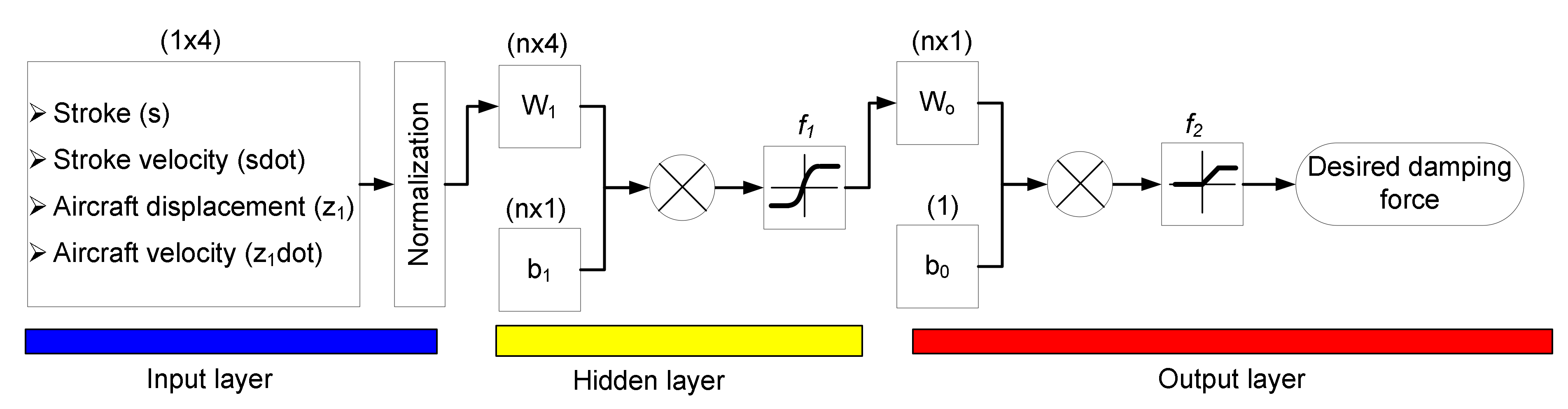
In order to solve these limitations of the hybrid controller, an intelligent controller based on a neural network is developed. The structure of the neural network is shown in Figure 10. The neural network consists of an input layer, a hidden layer, and an output layer. There are four input signals: stroke, stroke velocity, aircraft displacement, and aircraft velocity. These feed into the input layer. It should be noted that, after training, the controller determines the command for the MR damper with respect to the inputs, i.e., real-time state variables, and does not require any knowledge of system properties or models. The inputs are normalized to [01] before being applied into the hidden layer for efficient learning. The hidden layer has only a single layer with neurons. The output of the neural network is the desired damping force command. The relationship between the input signal (x) and the output signal (y) can be given by:
where:
The target data for the supervised learning are generated by the drop test experiments using the hybrid controller with exact mass and force information, the latter of which is measured by the load cell. The experimental data of the hybrid controller are divided into the training set and testing set. The training set contains the experimental results from 27 landing cases of the combinations of = 150 kg, 190 kg, 230 kg, and = 1−3 m/s with a step of 0.25 m/s. The testing set is composed of the experimental results from 18 landing cases of intermediate mass values = 170 kg and 210 kg and the same sink speeds.
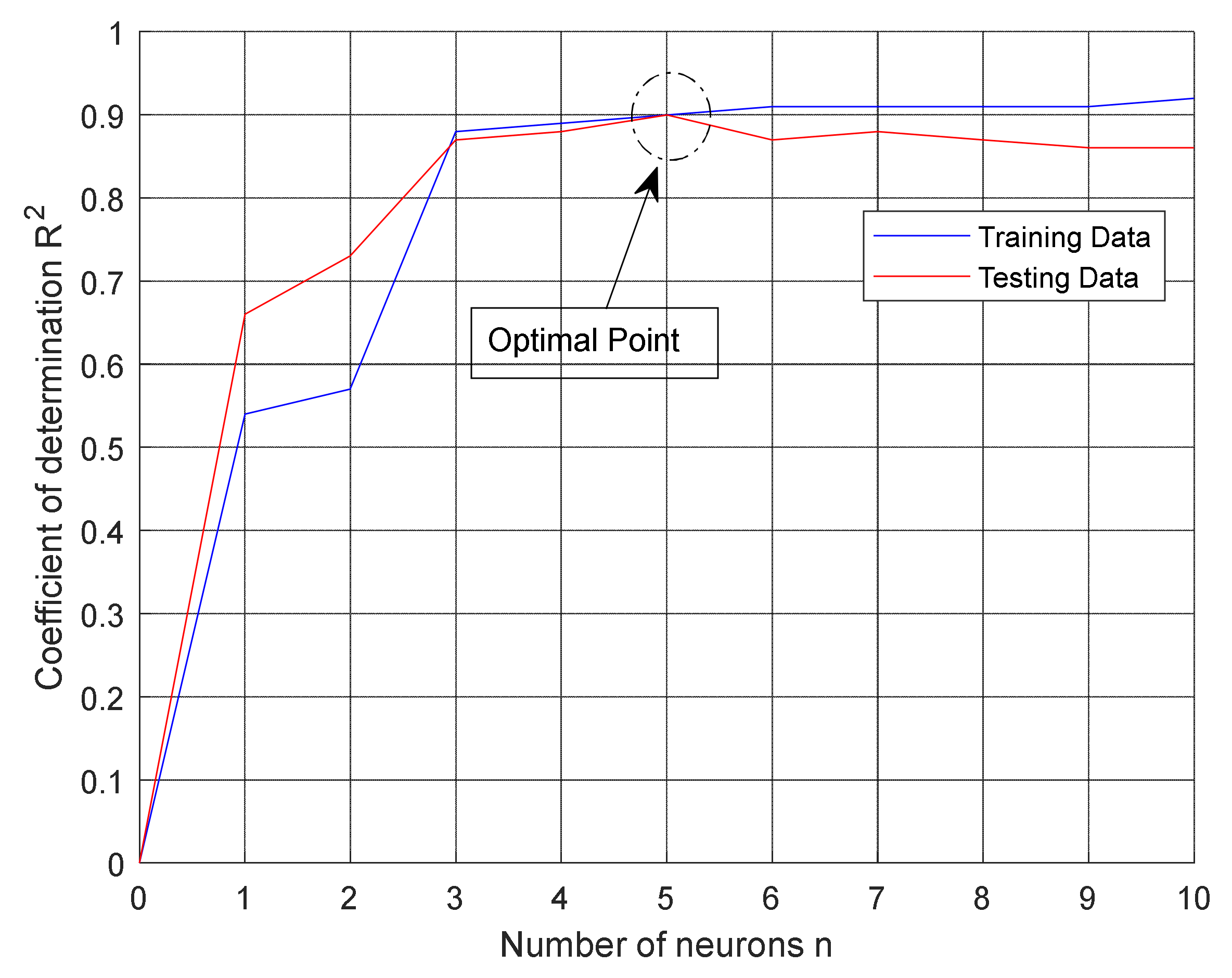
In this research, the neural network design toolbox in MATLAB [25,26] is used to determine the optimal parameter in the neural network. To evaluate the performance of the neural network, the coefficient of determination is defined by:
where represents the calculated values of and is the mean of [27]. Figure 11 shows the coefficient of determination for varying numbers of neurons with the testing set and training set. As the number of neurons increases, the coefficient of determination with training data also increases, but at a diminishing rate. The coefficient of determination with testing data is maximized when five neurons are used in the hidden layer, which seems to be optimal, and reduces after the point due to overfitting. All the parameters in the neural network after training are given in Table 2.
6. Experimental Results and Discussion
6.1. Comparison between the Hybrid Controller with Ideal Information and Intelligent Controller
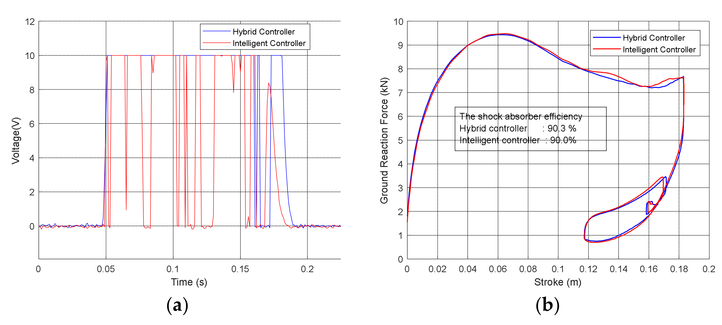
Figure 12 and Figure 13 show the experimental results of the hybrid controller, with given load cell data and exactly known aircraft mass, and the intelligent controller in a testing case of = 210 kg, = 3 m/s, and a training case of = 230 kg, = 3 m/s. The proposed controller seems to roughly regenerate the command of the hybrid controller in both the training and testing cases, and produces very similar efficiency curves. The difference in shock absorber efficiency between both controllers is less than 1%. Thus, the proposed controller shows good performance without requiring either the load cell data or knowledge of the aircraft mass.
Table 3 presents the landing performance of the hybrid controller and intelligent controller in 15 different landing conditions. In all training and test landing cases, while the shock absorber efficiency of the controllers varies from 77% to 90%, they exhibit similar performance. There are slight differences between the two controllers, which are less than 3% for all cases. Overall, the proposed controller attains comparable performance with the target controller in ideal environment in different landing scenarios without the shortcomings assumed in the target controller.
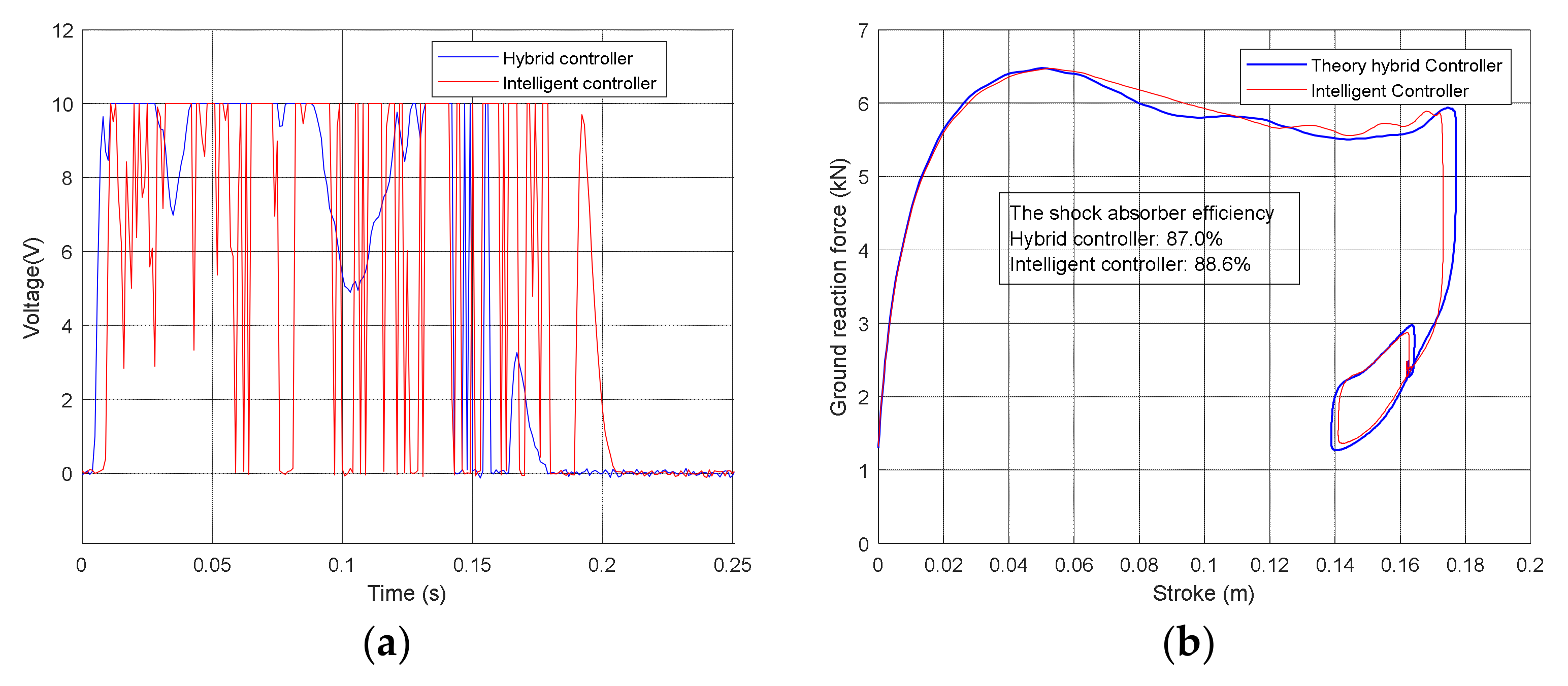
In order to verify the generalization ability of the neural network, drop tests in 12 other landing cases, out of the training and test sets, were executed. Figure 14 shows the experimental results of = 220 kg, = 2.32 m/s. Compared to the hybrid controller, the proposed controller exhibits similar performance. There is a small gap of less than 2% in shock absorber efficiency between the two controllers. Table 4 details the comparative experimental results of the hybrid controller and the proposed controller in the 12 landing cases. It can be seen that the proposed controller produces a marginally higher maximum ground reaction force compared to the hybrid controller. However, it achieves a slightly smaller maximum stroke. Thus, both the proposed controller and the hybrid controller are comparable in shock absorber efficiency. The difference in shock absorber efficiency between the two controllers is less than 3% in all 12 cases.
6.2. Comparison between the Hybrid Controller with Estimates and Intelligent Controller
Thus far, the hybrid controller is assumed to obtain the load cell data for the ground reaction force and exact aircraft mass. However, in the practical operation environment of aircraft landing gear, only the estimates of the force and mass are available. For selecting the skyhook gain and computing the desired damping force, the strut force in the damper needs is estimated instead of [17].
where is the cross-area of the head piston, is the initial air chamber charging pressure, is the polytropic process index, is the atmospheric pressure, is the initial air chamber volume, and are nonlinear viscous force constants. All parameters in Equation (12) are defined from previous studies [11,17]. The aircraft mass is assumed to be estimated in flight with approximately 5% error. In order to compare the controllers in practical assumptions, drop tests are executed by applying the proposed controller and the hybrid controller without load cell data, and thus the damping force is estimated by using Equation (12) and the aircraft mass is given with a 5% random error.
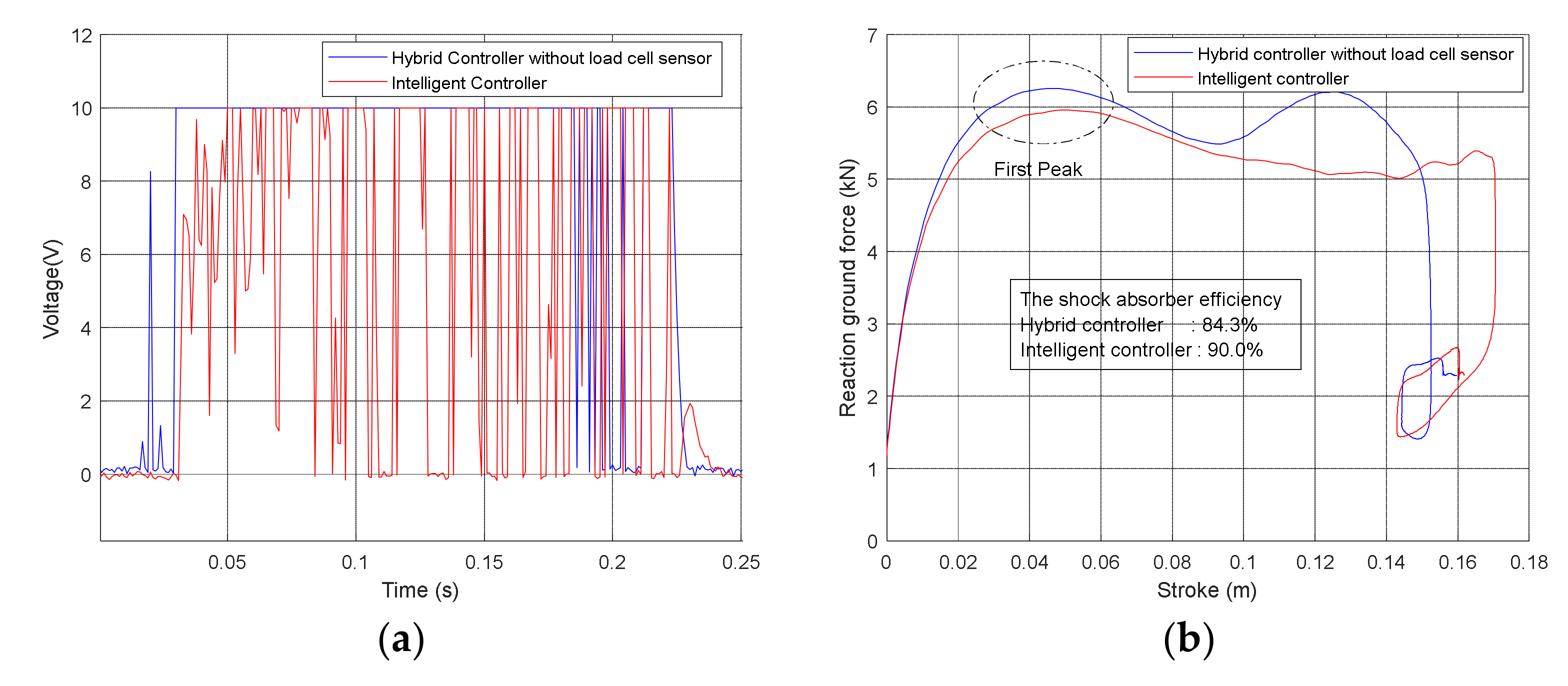
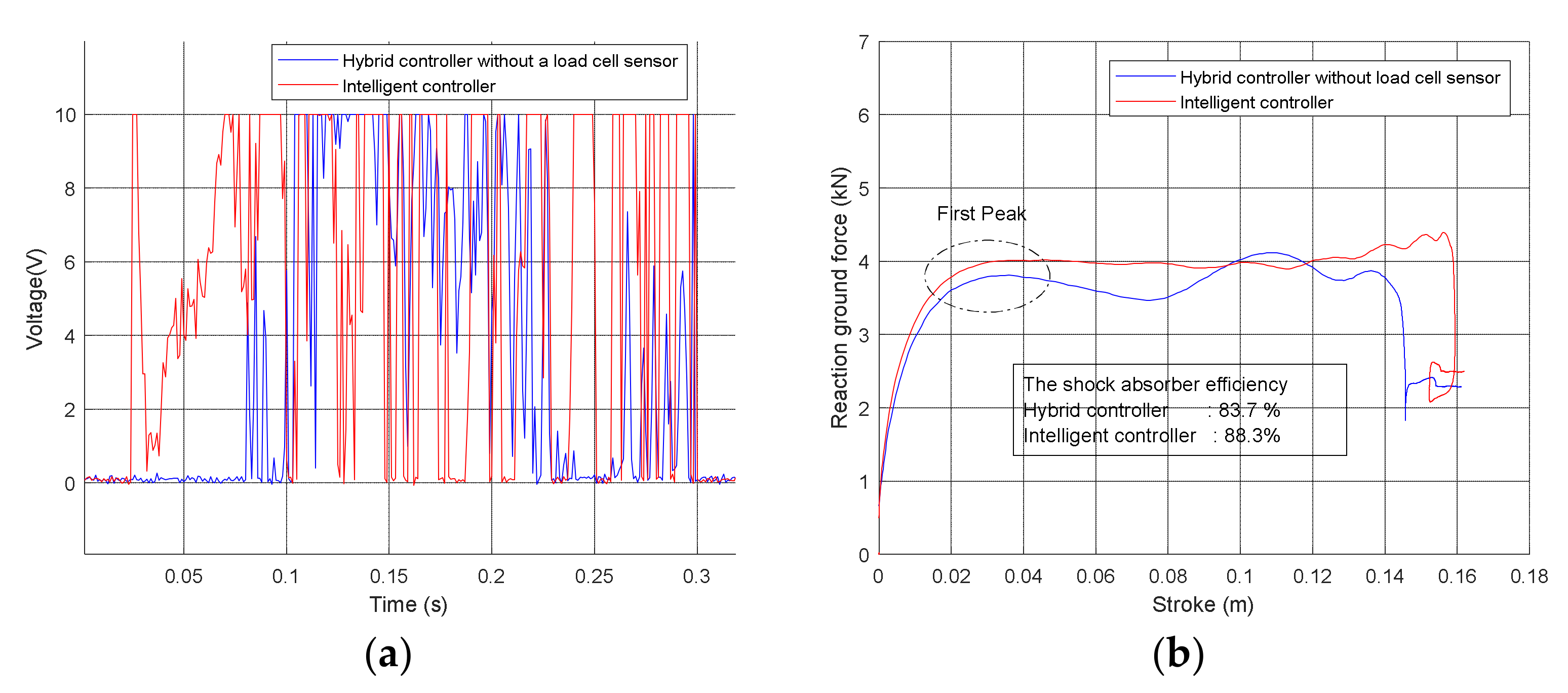
The drop test experimental results with the hybrid controller and the intelligent control are shown in Figure 15 and Figure 16 and Table 5. The neural network produced lower damping forces and higher efficiency than the hybrid controller for all cases. Because the aircraft mass estimate has some error, the skyhook gain cannot be well tuned so that the flatness of the efficiency curves of the hybrid controller is degraded. Moreover, in the hybrid controller, because the struct force is estimated instead of using the measured ground reaction force, the control input of the force control rule in Equation (6) cannot be accurate during the first compression phase, where the upper envelope of the efficiency curve forms. Thus, at the first peak, the damping force of the hybrid controller is lower or higher than the intelligent controller, as can be seen in Figure 15 and Figure 16. On the other hand, the intelligent controller does not require any information about strut force or landing conditions. Therefore, the intelligent controller exhibits better performance than the hybrid controller in this practical condition of aircraft landing. The shock absorber efficiency is up to 6% more than that of the hybrid controller.
Generally, the theoretical hybrid controller required the exact aircraft mass and force information in order to produce good landing performance. Without the exact aircraft mass, the skyhook gain is different from the optimal value. Thus, the shock absorber efficiency is degraded. Moreover, the error in the mathematical model also reduces the landing performance. The intelligent controller based on supervised learning is trained using the data from the theoretical hybrid controller with the exact aircraft mass and force information. Thus, the intelligent controller exhibits similar performance to the theoretical hybrid controller without any information about strut force or aircraft mass.
7. Conclusions
This paper presents an application of supervised neural network control for a landing gear equipped with an MR damper in various landing scenarios. Experimental environments for drop tests of the landing gear were set up for different aircraft masses and sink speeds based on the dSPACE platform, which provides real-time control by models in Simulink. The hybrid controller, which has demonstrated high performance among the existing techniques in both the simulation and experiments, was set as the target model of the supervised learning and was provided with the exact mass of the aircraft and the measured ground reaction force. The neural network controller receives only the system’s state variables as input and does not require any information on the aircraft mass or strut force. In the actual operating situations of the aircraft landing gear, only the model-dependent estimates of the aircraft mass and forces are available for control, which degrades the performance of the existing controller. On the other hand, the proposed artificial neural network controller reproduces the behavior of a hybrid controller, which shows the best performance under ideal ground experiment conditions, using only the system state variable information. Therefore, the proposed controller could maintain superior performance to the existing controllers and proved this through comparative experiments. The main results show that the proposed controller exhibits similar landing performance to the hybrid controller with exact information. There is a small difference of 1–3% in shock absorber efficiency between the two controllers. Moreover, the proposed controller produces better shock absorber efficiency by up to 6% than the hybrid controller without exact information. In the future, a robust controller based on sliding model control will be designed to improve the robustness of the MR damper.
Author Contributions
Data curation, Q.-V.L., B.-H.J. and D.-S.J.; Formal analysis, Q.-V.L., B.-H.J. and D.-S.J.; Investigation, D.-S.J. and J.-H.H.; Methodology, D.-S.J. and J.-H.H.; Project administration, J.-H.H.; Software, Q.-V.L. and B.-H.J.; Supervision, D.-S.J. and J.-H.H.; Writing—original draft, Q.-V.L.; Writing—review and editing, B.-H.J., D.-S.J. and J.-H.H. All authors have read and agreed to the published version of the manuscript.
Funding
This work was funded by the Ministry of Trade, Industry & Energy (MOTIE, Korea), grant number 10073291.
Acknowledgments
This work was supported by the Technology Innovation Program (intelligent landing gear with variable damping force for 1500lb class) (10073291).
Conflicts of Interest
The authors declare no conflict of interest.
References
- 14 CFR 25—Airworthiness Standards: Transport Category Airplanes. Available online: https://www.govinfo.gov/app/details/CFR-2011-title14-vol1/CFR-2011-title14-vol1-part25/summary (accessed on 7 December 2021).
- Puma-Araujo, S.D.; Olvera-Trejo, D.; Martínez-Romero, O.; Urbikain, G.; Elías-Zúñiga, A.; López de Lacalle, L.N. Semi-Active Magnetorheological Damper Device for Chatter Mitigation during Milling of Thin-Floor Components. Appl. Sci. 2020, 10, 5313. [Google Scholar] [CrossRef]
- Symans, M.D.; Constantinou, M.C. Semi-Active Control Systems for Seismic Protection of Structures: A State-of-the-Art Review. Eng. Struct. 1999, 21, 469–487. [Google Scholar] [CrossRef]
- Ahmadian, M.; Poynor, J.C. An Evaluation of Magneto Rheological Dampers for Controlling Gun Recoil Dynamics. Shock. Vib. 2001, 8, 147–155. [Google Scholar] [CrossRef]
- Choi, S.-B.; Han, Y.-M. Magnetorheological Fluid Technology Applications in Vehicle Systems, 1st ed.; Taylor & Francis Group: Abingdon, UK, 2012; ISBN 978-0-429-11055-9. [Google Scholar]
- Mikułowski, G.; Jankowski, Ł. Adaptive Landing Gear: Optimum Control Strategy and Potential for Improvement. Shock. Vib. 2009, 16, 175–194. [Google Scholar] [CrossRef]
- Choi, Y.-T.; Robinson, R.; Hu, W.; Wereley, N.M.; Birchette, T.S.; Bolukbasi, A.O.; Woodhouse, J. Analysis and Control of a Magnetorheological Landing Gear System for a Helicopter. J. Am. Helicopter Soc. 2016, 61, 1–8. [Google Scholar] [CrossRef]
- Dong, X.M.; Xiong, G.W. Vibration Attenuation of Magnetorheological Landing Gear System with Human Simulated Intelligent Control. Math. Probl. Eng. 2013, 2013, 242476. [Google Scholar] [CrossRef] [Green Version]
- Choi, Y.-T.; Wereley, N.M. Vibration Control of a Landing Gear System Featuring Electrorheological/Magnetorheological Fluids. J. Aircr. 2003, 40, 432–439. [Google Scholar] [CrossRef]
- Young-O, H.; Jae-Up, H.; Jae-Hyuk, H.; Jae-Sung, B.; Kyoung-Ho, L.; Doo-Man, K.; Tae-Wook, K. Force Control of Main Landing Gear using Magneto-Rheological Damper. J. Korean Soc. Aeronaut. Space Sci. 2009, 37, 344–349. [Google Scholar] [CrossRef]
- Luong, Q.V.; Jang, D.-S.; Hwang, J.-H. Robust Adaptive Control for an Aircraft Landing Gear Equipped with a Magnetorheological Damper. Appl. Sci. 2020, 10, 1459. [Google Scholar] [CrossRef] [Green Version]
- Russell, S.; Norvig, P. Artificial Intelligence: A Modern Approach, 3rd ed.; Prentice Hall: Upper Saddle River, NJ, USA, 2009; ISBN 978-0-13-604259-4. [Google Scholar]
- Badue, C.; Guidolini, R.; Carneiro, R.V.; Azevedo, P.; Cardoso, V.B.; Forechi, A.; Jesus, L.; Berriel, R.; Paixão, T.M.; Mutz, F.; et al. Self-Driving Cars: A Survey. Expert Syst. Appl. 2021, 165, 113816. [Google Scholar] [CrossRef]
- Mosavi, A.; Varkonyi, A. Learning in Robotics. Int. J. Robot. Res. 2017, 157, 8–11. [Google Scholar] [CrossRef]
- Xu, Q.; Chen, J.; Liu, X.; Li, J.; Yuan, C. An ABC-BP-ANN Algorithm for Semi-Active Control for Magnetorheological Damper. KSCE J. Civ. Eng. 2017, 21, 2310–2321. [Google Scholar] [CrossRef]
- Luong, Q.V.; Jang, D.-S.; Hwang, J.-H. Intelligent Control Based on a Neural Network for Aircraft Landing Gear with a Magnetorheological Damper in Different Landing Scenarios. Appl. Sci. 2020, 10, 5962. [Google Scholar] [CrossRef]
- Jo, B.-H.; Jang, D.-S.; Hwang, J.-H.; Choi, Y.-H. Experimental Validation for the Performance of MR Damper Aircraft Landing Gear. Aerospace 2021, 8, 272. [Google Scholar] [CrossRef]
- MRF-140CG Magneto-Rheological Fluid—1 Liter. Available online: http://www.lordmrstore.com/lord-mr-products/mrf-140cg-magneto-rheological-fluid (accessed on 6 March 2021).
- Currey, N.S. Aircraft Landing Gear Design: Principles and Practices; AIAA Education Series; AIAA: Reston, VA, USA, 1988; ISBN 978-0-930403-41-6. [Google Scholar]
- Han, C.; Kim, B.-G.; Choi, S.-B. Design of a New Magnetorheological Damper Based on Passive Oleo-Pneumatic Landing Gear. J. Aircr. 2018, 55, 2510–2520. [Google Scholar] [CrossRef]
- Lee, D.Y.; Nam, Y.J.; Yamane, R.; Park, M.K. Performance Evaluation on Vibration Control of MR Landing Gear. J. Phys. Conf. Ser. 2009, 149, 012068. [Google Scholar] [CrossRef]
- Karnopp, D.; Crosby, M.J.; Harwood, R.A. Vibration Control Using Semi-Active Force Generators. J. Eng. Ind. 1974, 96, 619–626. [Google Scholar] [CrossRef]
- Slotine, J.-J.E.; Li, W. Applied Nonlinear Control; Prentice-Hall International: Upper Saddle River, NJ, USA, 1991; ISBN 0-13-040890-5. [Google Scholar]
- Sun, J.; Ellerbroek, J.; Hoekstra, J.M. Aircraft Initial Mass Estimation Using Bayesian Inference Method. Transp. Res. Part C Emerg. Technol. 2018, 90, 59–73. [Google Scholar] [CrossRef] [Green Version]
- Hagan, M.T.; Demuth, H.B.; Beale, M.H.; De Jesús, O. Neural Network Design, 2nd ed.; Martin Hagan, Univerity of Kansas: Lawrence, KS, USA, 2014; ISBN 0-9717321-1-6. [Google Scholar]
- Workflow for Neural Network Design. Available online: https://www.mathworks.com/help/deeplearning/ug/workflow-for-neural-network-design.html (accessed on 9 January 2021).
- Linear Regression. Available online: https://www.mathworks.com/help/matlab/data_analysis/linear-regression.html (accessed on 10 September 2021).
Figure 1.
Structure of drop test apparatus.

Figure 2.
Sensors and signal processing units of the drop test apparatus.

Figure 3.
Structure of landing gear equipped with MR damper.

Figure 4.
Components of the MR damper (landing gear without tire).

Figure 5.
Efficiency curve of a typical landing gear.

Figure 6.
(a) Principles of hybrid controller, (b) hybrid control block. Hybrid controller with a load cell sensor and known aircraft mass method.
Figure 6.
(a) Principles of hybrid controller, (b) hybrid control block. Hybrid controller with a load cell sensor and known aircraft mass method.

Figure 7.
Skyhook gain surface.

Figure 8.
(a) Voltage applied to MR core, (b) efficiency curve. The drop test results of the landing gear using the passive damper, skyhook controller, and hybrid controller in the case of m1 = 190 kg, v = 1 m/s.
Figure 8.
(a) Voltage applied to MR core, (b) efficiency curve. The drop test results of the landing gear using the passive damper, skyhook controller, and hybrid controller in the case of m1 = 190 kg, v = 1 m/s.

Figure 9.
Control scheme in practical operation environment.

Figure 10.
The structure of the neural network.

Figure 11.
The coefficient of determination over the number of neurons with the testing data and training data.
Figure 11.
The coefficient of determination over the number of neurons with the testing data and training data.

Figure 12.
(a) Voltage applied to MR core, (b) efficiency curve. The drop test results of the landing gear using the hybrid controller with exact information and intelligent controller in the case of m1 = 210 kg, v = 3 m/s (testing case).
Figure 12.
(a) Voltage applied to MR core, (b) efficiency curve. The drop test results of the landing gear using the hybrid controller with exact information and intelligent controller in the case of m1 = 210 kg, v = 3 m/s (testing case).

Figure 13.
(a) Voltage applied to MR core, (b) efficiency curve. The drop test results of the landing gear using the hybrid controller with exact information and intelligent controller in the case of m1 = 230 kg, v = 3 m/s (training case).
Figure 13.
(a) Voltage applied to MR core, (b) efficiency curve. The drop test results of the landing gear using the hybrid controller with exact information and intelligent controller in the case of m1 = 230 kg, v = 3 m/s (training case).

Figure 14.
(a) Voltage applied to MR core, (b) efficiency curve. The drop test results of the landing gear using the hybrid controller with exact information and intelligent controller in the case of m1 = 220 kg, v = 2.32 m/s (different from training and testing cases).
Figure 14.
(a) Voltage applied to MR core, (b) efficiency curve. The drop test results of the landing gear using the hybrid controller with exact information and intelligent controller in the case of m1 = 220 kg, v = 2.32 m/s (different from training and testing cases).

Figure 15.
(a) Voltage applied to MR core, (b) efficiency curve. The performance of the landing gear using the hybrid controller without exact data and intelligent controller in the case of m1 = 210 kg, v = 2 m/s.
Figure 15.
(a) Voltage applied to MR core, (b) efficiency curve. The performance of the landing gear using the hybrid controller without exact data and intelligent controller in the case of m1 = 210 kg, v = 2 m/s.

Figure 16.
(a) Voltage applied to MR core, (b) efficiency curve. The performance of the landing gear using the hybrid controller without exact data and intelligent controller in the case of m1 = 230 kg, v = 1 m/s.
Figure 16.
(a) Voltage applied to MR core, (b) efficiency curve. The performance of the landing gear using the hybrid controller without exact data and intelligent controller in the case of m1 = 230 kg, v = 1 m/s.


Table 1.
Damper performance using passive damping, skyhook controller, and hybrid controller in differing landing cases. The best result for each criterion is marked in bold.
Table 1.
Damper performance using passive damping, skyhook controller, and hybrid controller in differing landing cases. The best result for each criterion is marked in bold.
| Passive Damper | Skyhook Control | Hybrid Control | ||||||||
|---|---|---|---|---|---|---|---|---|---|---|
| η (%) | η (%) | η (%) | ||||||||
| m1 = 150 kg | v = 1 m/s | 3.09 | 0.160 | 81.4 | 3.09 | 0.16 | 81.4 | 3.85 | 0.148 | 84.9 |
| v = 2 m/s | 5.55 | 0.168 | 72.4 | 5.55 | 0.168 | 72.4 | 5.36 | 0.150 | 79.4 | |
| v = 3 m/s | 8.59 | 0.176 | 72.5 | 8.59 | 0.176 | 72.5 | 8.60 | 0.157 | 81.0 | |
| m1 = 190 kg | v = 1 m/s | 3.90 | 0.174 | 72.8 | 3.51 | 0.169 | 84.2 | 3.34 | 0.166 | 89.6 |
| v = 2 m/s | 5.83 | 0.182 | 78.2 | 5.83 | 0.182 | 78.2 | 5.90 | 0.167 | 85.3 | |
| v = 3 m/s | 9.21 | 0.188 | 77.5 | 9.21 | 0.188 | 77.5 | 9.17 | 0.176 | 83.0 | |
| m1 = 230 kg | v = 1 m/s | 5.20 | 0.180 | 65.3 | 4.17 | 0.172 | 85.5 | 3.93 | 0.172 | 90.5 |
| v = 2 m/s | 6.84 | 0.186 | 75.6 | 6.81 | 0.183 | 77.9 | 6.16 | 0.184 | 85.8 | |
| v = 3 m/s | 9.93 | 0.194 | 80.6 | 9.93 | 0.194 | 80.6 | 9.78 | 0.191 | 85.1 | |
Table 2.
Trained neural network parameters.
| −2.536 | 4.404 | −1.489 | 3.334 | −1.500 | |
| −3.407 | 3.212 | −0.015 | 3.467 | −1.293 | |
| −3.215 | −2.024 | 8.346 | 1.070 | 6.579 | |
| 3.299 | 2.796 | 56.78 | −0.758 | −6.821 | |
| 5.773 | −7.054 | 3.541 | −6.433 | 4.576 | |
| 25.91 | −24.22 | 16.95 | 46.08 | −36.71 | |
| 15.75 | |||||
Table 3.
Damper performance using the hybrid controller with exact information and intelligent controller in training and testing cases. The best efficiency for each case is marked in bold.
Table 3.
Damper performance using the hybrid controller with exact information and intelligent controller in training and testing cases. The best efficiency for each case is marked in bold.
| Training Set | Testing Set | |||||||||||||
|---|---|---|---|---|---|---|---|---|---|---|---|---|---|---|
| Hybrid Control | Intelligent Control | Hybrid Control | Intelligent Control | |||||||||||
| η (%) | η (%) | η (%) | η (%) | |||||||||||
| m1 = 150 kg | v = 1 m/s | 3.15 | 0.143 | 78.6 | 3.60 | 0.142 | 76.9 | m1 = 170 kg | 3.49 | 0.159 | 80.6 | 3.61 | 0.147 | 82.1 |
| v = 2 m/s | 5.77 | 0.149 | 77.6 | 5.75 | 0.144 | 76.6 | 5.82 | 0.153 | 82.1 | 5.83 | 0.153 | 82.3 | ||
| v = 3 m/s | 9.06 | 0.155 | 79.7 | 9.06 | 0.154 | 78.9 | 9.11 | 0.164 | 81.2 | 8.95 | 0.167 | 81.2 | ||
| m1 = 190 kg | v = 1 m/s | 3.58 | 0.170 | 89.6 | 3.60 | 0.155 | 87.9 | m1 = 210 kg | 3.74 | 0.163 | 90.3 | 3.81 | 0.160 | 90.0 |
| v = 2 m/s | 6.19 | 0.161 | 85.1 | 5.97 | 0.162 | 84.7 | 5.88 | 0.176 | 86.6 | 5.96 | 0.171 | 87.5 | ||
| v = 3 m/s | 9.69 | 0.174 | 82.1 | 9.32 | 0.176 | 82.6 | 9.43 | 0.183 | 84.6 | 9.48 | 0.183 | 84.2 | ||
| m1 = 230 kg | v = 1 m/s | 4.11 | 0.168 | 90.6 | 4.39 | 0.162 | 88.3 | |||||||
| v = 2 m/s | 6.14 | 0.181 | 86.5 | 6.46 | 0.173 | 89.6 | ||||||||
| v = 3 m/s | 9.69 | 0.189 | 85.8 | 9.95 | 0.186 | 86.2 | ||||||||
Table 4.
Damper performance using the hybrid controller with exact information and intelligent controller in other cases, which are different to training and testing cases. The best efficiency for each case is marked in bold.
Table 4.
Damper performance using the hybrid controller with exact information and intelligent controller in other cases, which are different to training and testing cases. The best efficiency for each case is marked in bold.
| Landing Conditions | Hybrid Control | Intelligent Control | ||||
|---|---|---|---|---|---|---|
| (kN) | (m) | η (%) | (kN) | (m) | η (%) | |
| Case 1: m1 = 220 kg, v = 1.83 m/s | 4.97 | 0.175 | 88.5 | 5.16 | 0.165 | 91.5 |
| Case 2: m1 = 220 kg, v = 2.32 m/s | 6.48 | 0.177 | 87.0 | 6.50 | 0.173 | 88.6 |
| Case 3: m1 = 220 kg, v = 2.85 m/s | 8.31 | 0.181 | 86.0 | 8.36 | 0.180 | 86.7 |
| Case 4: m1 = 200 kg, v = 1.88 m/s | 4.97 | 0.162 | 88.7 | 5.07 | 0.157 | 88.0 |
| Case 5: m1 = 200 kg, v = 2.31 m/s | 6.38 | 0.166 | 86.4 | 6.43 | 0.165 | 85.8 |
| Case 6: m1 = 200 kg, v = 2.81 m/s | 8.13 | 0.172 | 85.2 | 8.20 | 0.173 | 84.4 |
| Case 7: m1 = 180 kg, v = 1.83 m/s | 4.81 | 0.151 | 85.4 | 5.00 | 0.152 | 83.1 |
| Case 8: m1 = 180 kg, v = 2.35 m/s | 6.27 | 0.153 | 85.4 | 6.36 | 0.155 | 84.0 |
| Case 9: m1 = 180 kg, v = 2.80 m/s | 7.94 | 0.160 | 84.5 | 7.89 | 0.163 | 83.0 |
| Case 10: m1 = 160 kg, v = 1.84 m/s | 4.73 | 0.148 | 79.6 | 4.92 | 0.145 | 78.4 |
| Case 11: m1 = 160 kg, v = 2.32 m/s | 6.24 | 0.147 | 80.9 | 6.25 | 0.147 | 81.1 |
| Case 12: m1 = 160 kg, v = 2.80 m/s | 7.75 | 0.149 | 82.9 | 7.82 | 0.152 | 81.0 |
Table 5.
Damper performance using real hybrid control without load cell sensor, and intelligent control in the testing cases. The best efficiency for each case is marked in bold.
Table 5.
Damper performance using real hybrid control without load cell sensor, and intelligent control in the testing cases. The best efficiency for each case is marked in bold.
| Hybrid Control Without Exact Data | Intelligent Control | ||||||
|---|---|---|---|---|---|---|---|
| (kN) | (m) | η (%) | (kN) | (m) | η (%) | ||
| m1 = 150 kg | v = 1 m/s | 3.89 | 0.146 | 71.2 | 3.60 | 0.142 | 74.9 |
| v = 2 m/s | 5.91 | 0.144 | 73.8 | 5.75 | 0.144 | 76.6 | |
| v = 3 m/s | 9.27 | 0.146 | 78.5 | 9.06 | 0.154 | 78.9 | |
| m1 = 170 kg | v = 1 m/s | 3.99 | 0.149 | 76.5 | 3.61 | 0.147 | 82.1 |
| v = 2 m/s | 5.93 | 0.152 | 79.8 | 5.83 | 0.153 | 82.3 | |
| v = 3 m/s | 9.55 | 0.160 | 81.4 | 8.95 | 0.167 | 81.6 | |
| m1 = 190 kg | v = 1 m/s | 4.06 | 0.152 | 82.5 | 3.60 | 0.155 | 87.9 |
| v = 2 m/s | 6.17 | 0.156 | 84.6 | 5.97 | 0.162 | 84.7 | |
| v = 3 m/s | 9.71 | 0.170 | 82.2 | 9.32 | 0.176 | 82.6 | |
| m1 = 210 kg | v = 1 m/s | 4.13 | 0.164 | 84.3 | 3.81 | 0.160 | 90.0 |
| v = 2 m/s | 6.25 | 0.160 | 87.1 | 5.96 | 0.171 | 87.5 | |
| v = 3 m/s | 9.88 | 0.178 | 83.7 | 9.48 | 0.183 | 84.2 | |
| m1 = 230 kg | v = 1 m/s | 4.24 | 0.172 | 83.7 | 4.39 | 0.162 | 88.3 |
| v = 2 m/s | 6.61 | 0.170 | 89.0 | 6.46 | 0.173 | 89.6 | |
| v = 3 m/s | 9.82 | 0.186 | 85.5 | 9.95 | 0.186 | 86.2 | |
Publisher’s Note: MDPI stays neutral with regard to jurisdictional claims in published maps and institutional affiliations. |
© 2021 by the authors. Licensee MDPI, Basel, Switzerland. This article is an open access article distributed under the terms and conditions of the Creative Commons Attribution (CC BY) license (https://creativecommons.org/licenses/by/4.0/).
Share and Cite
MDPI and ACS Style
Luong, Q.-V.; Jo, B.-H.; Hwang, J.-H.; Jang, D.-S. A Supervised Neural Network Control for Magnetorheological Damper in an Aircraft Landing Gear. Appl. Sci. 2022, 12, 400. https://0-doi-org.brum.beds.ac.uk/10.3390/app12010400
AMA Style
Luong Q-V, Jo B-H, Hwang J-H, Jang D-S. A Supervised Neural Network Control for Magnetorheological Damper in an Aircraft Landing Gear. Applied Sciences. 2022; 12(1):400. https://0-doi-org.brum.beds.ac.uk/10.3390/app12010400
Chicago/Turabian StyleLuong, Quoc-Viet, Bang-Hyun Jo, Jai-Hyuk Hwang, and Dae-Sung Jang. 2022. "A Supervised Neural Network Control for Magnetorheological Damper in an Aircraft Landing Gear" Applied Sciences 12, no. 1: 400. https://0-doi-org.brum.beds.ac.uk/10.3390/app12010400
Note that from the first issue of 2016, this journal uses article numbers instead of page numbers. See further details here.