Article

Analytical Method for the Bending Resistance of Slim Floor Beams with Asymmetric Double-T Steel Section under ISO Fire

1
Department of Steel Structures and Structural Mechanics, The Politehnica University of Timisoara, 300224 Timisoara, Romania
2
ArcelorMittal Steligence, L-4221 Esch-sur-Alzette, Luxembourg
*
Author to whom correspondence should be addressed.
Submission received: 2 November 2021 / Revised: 29 December 2021 / Accepted: 31 December 2021 / Published: 7 January 2022
(This article belongs to the Special Issue New Challenges in Civil Structure for Fire Response)

Abstract

:

Featured Application

The simplified method can be used by practitioner engineers as a tool for computing the fire resistance of slim floor beams with double-T steel section.

Abstract

The slim floor beams, characterized by the steel profile embedded in the concrete slab, may be found in different configurations, based on the shape of the steel profile cross-section, which can vary from a rectangular to double-T section. While the most common shape used nowadays is the double-T cross-section, the Eurocodes do not provide a simplified method for the fire resistance assessment. The literature offers a simplified method for computation of bending resistance under elevated temperature, based on existing research on thermal models, and was validated for a particular type of slim floor beams (SFB). The current study extends the scope of application of this method, for different types of slim floor beam, which include an asymmetric double-T steel cross-section. The objective was reached through a numerical procedure, by analyzing 162 configurations subjected to four different fire requirements (R30, R60, R90, R120), resulting in a total of 648 analyses, performed with a validated numerical model in SAFIR software. The results in terms of bending resistance showed that the simplified method represents a strong tool for the fire design of slim floor beams.

1. Introduction

In slim floor (or shallow floor) systems, the beams are integrated in the thickness of the slab, thus reducing the height of the floor. The first slim floor system appeared in England during the last decade of the nineteenth century, as the Jack arch floor system [1], made of double-T section steel beams with flat masonry arches in-between. Although this flooring system was very popular [2], improvement has been made by replacing the masonry with the concrete material, which provides better behavior under horizontal dynamic loads [3].
Nowadays, there are different types of slim floor beam made of steel and concrete [4]. While in all existing configurations, the steel profile is embedded in the concrete slab, the shape of the steel profile cross-section can vary from rectangular [5,6,7] to double-T shapes [7,8,9,10,11]. However, the steel double-T cross-section remains the most widely used.
A common and economical slim floor beam configuration was developed by ArcelorMittal in the 1990s, consisting of a double-T profile with a welded plate underneath (SFB, slim floor beam) or of an asymmetric double-T profile with the bottom flange wider than the upper flange (IFB, integrated floor beam), as shown in Figure 1 [7]. The composite behavior is ensured by a concrete dowel, placed perpendicular to the steel profile web and embedded in the concrete poured in situ (Figure 2).
Other asymmetrical double-T steel beams can be realized by direct manufacturing (ASB type, Figure 3a) [12], by welded plates (Figure 3b), or by reducing the width of the top flange of a European H-profile (SB type, Figure 3d).
Slim floor systems present a series of advantages, among which are their inherent fire resistance, as the bottom flange is the unique part directly exposed to fire. Extensive experimental research has been conducted in the last decades [13,14,15], which demonstrated an enhanced fire resistance compared to the classical composite beams, without additional fire protection. The fire resistance of slim floor beams can be determined by numerical simulations or by experimental tests. Despite their popularity, the standards do not yet comprise a regulated method for the fire design of such elements. The Eurocodes offer the possibility to compute a mean value of temperature on the entire cross section of an element, based on its section factor. This method cannot be applied in case of slim floor beams, as the steel profile is embedded in concrete, thus resulting in temperature variation along the height.
Zaharia and Franssen [15] proposed a simplified method for calculating the temperature in the steel profile (on lower flange and along the web height) and in the rebars above the bottom flange. This method was developed based on numerical simulations of an IFB system, subjected to an ISO fire. Hanus et al. [16] proposed an improved equation to calculate the temperature in the reinforcement bars placed longitudinally. The set of equations was obtained from isotherms of the EN 1992-1-2 [17], used there for the computation of temperature on concrete element cross-sections. A correct evaluation of the rebars temperature is very important, especially for high fire resistance requirements. The temperature evolution on the lower plate and lower flange of an SFB type was analyzed by Cajot et al. [18] and Romero [19]. They noticed a positive influence of thermal resistance at the interface between the lower flange and the plate welded beneath [20].
Recently, Zanon et al. [21] presented a simplified method for the fire design of slim floor beams, based on the models existing in the literature, i.e., Zaharia and Franssen [15], Hanus et al. [16], Cajot [18] and Romero et al. [19]. The authors [21] integrated the previously developed equations, and proposed a unitary concept with some adaptations to ensure consistency of results within the given field of application.
Zanon et al. [21] validated the method with a comprehensive analysis of tests and a broad numerical parametric study, but only for one type of slim floor beams(SFB type, which consists in a double-T profile with a supplementary wider plate welded below the bottom flange). The current study aims to extend the scope of application of Zanon et al.’s [21] method for different configurations of slim floor beams, made of asymmetric double-T steel cross-sections, in which no supplementary plate is welded on the bottom of the profile. The objective was reached through a numerical procedure, by analysing 162 configurations subjected to four different fire requirements (R30, R60, R90, R120) resulting in a total of 648 numerical analyses. Simulations were carried out with the SAFIR software, using a validated numerical model, and existing experimental data from the literature [13]. The study covers the configurations presented in Figure 3.

2. Validation of the Numerical Model

The numerical simulations were performed with the SAFIR software [22]. The numerical model was validated against two previous experimental tests existing in the literature [23,24].

2.1. Experimental Tests

A series of experimental tests were carried out in the 1990s, in 21 configurations of different types of slim floor beams, and a final compendium was written in 2008 [13]. Among these configurations, two were considered herein for the validation of the numerical model: WFRC 44174 [23] and WFRC 66162 [24]. The steel beams in the experimental tests were double-T profiles (Figure 4), similar to the slim floor beam types assessed in this study (only the steel profile, no supplementary plate welded under the bottom flange).
The selected experimental tests, conducted in 1989 [23] and 1996 [24], respectively, at the Warrington Fire Research Center, consisted of a simply supported beam with a 4.5 m distance between the supports. The test assemblies were placed on top of the oven, with the beam supports outside of the oven, in such a way that only a 4 m span was heated under ISO fire. They were loaded through four hydraulic rams, along the longitudinal axis of the steel profile, in four points at 1/8, 3/8, 5/8, and 7/8 of the supported span. The load applied through each ram was 76.59 kN for the WFRC 44174 test and 84.6 kN for the WFRC 66162 test, respectively.
Figure 4a shows the cross-section of the WFRC 44174 composite behavior test, with a 254 × 254 mm, S275 steel profile, and the upper part embedded in a Grade 30 light weight concrete slab. The bottom part of the steel profile was covered with Grade 30 normal weight concrete, and the lower flange remained exposed. The tensile test made on a material sample taken from the tested steel profile showed a value of 267 N/mm2 for the yield strength.
Figure 4b shows the cross-section of WRFC 66162 non-composite behavior test, realized of an asymmetric 280 mm deep 280/180 mm wide hot rolled profile, steel grade S355. On the lower flange, a 210 mm deep metal decking was placed to support the Grade 30 normal weight concrete cast in place. The tensile test made on a material sample taken from the steel profile showed a value of 402 N/mm2 for yield strength.
The failure criterion was considered when reaching a vertical displacement of l/20 of span, in both configurations. The WFRC 44174 test was stopped when the vertical displacement at mid-span reached 226 mm after 52 min, while the WFRC 66162 test was stopped at 225 mm after 107.5 min.

2.2. Validated Model

The material properties used in the numerical models are according to the fire design Eurocodes [17,25,26,27]. For the thermal analysis, the emissivity used was 0.7 for both steel and concrete, on heated surfaces as well as on unheated surfaces, whereas the coefficient of convection was 25 W/m2K on heated surfaces and 4 W/m2K on unheated surfaces, for both materials. The upper limit of the thermal conductivity was considered for concrete. For experiment No. 66162, the value of concrete density was considered 2300 kg/m3. For experiment No. 44174, the measured concrete density was 2200 kg/m3 for normal weight concrete and 1850 kg/m3 for light weight concrete. The moisture content of the concrete was taken in accordance to the technical notes of the experimental tests [23,24]. For experiment No. 44174, the measured moisture content was 39 kg/m3 for normal weight concrete and 47 kg/m3 for light weight concrete. For experiment No. 66162, the moisture content was 42 kg/m3. Safir software takes into account the energy dissipated by the evaporation of free water, in concrete. This energy is resealed at a constant rate from 100 °C to 115 °C, and then the energy release rate is linearly decreasing from 115 °C to 200 °C [22].
The cross-sections of the beam were exposed to the ISO fire only from below, the temperature in the air on the top of the floor being considered 20 °C.
To describe the geometry of the cross section and the temperature distribution, linear isoparametric finite elements were used [22]. A 2D thermal analysis was realized on the cross-sections with triangle shape elements to describe the meshing. For the mechanical model, 2D beam finite elements were used, with constant cross-section along the longitudinal axis. The thermal analysis and the mechanical analysis were realized separately and subsequently, which means that the temperature distribution would obviously influence the mechanical response, but the opposite was not true [22]. In the cases with non-composite behaviour, the concrete material was considered only with thermal properties, but no mechanical properties. Thus, the presence of the concrete influenced the thermal analysis, but not the mechanical one.
The boundary conditions and the loads were considered as in the fire resistance tests. The mechanical models, for both tests, consisted of 4.5 m simply supported beams, heated over 4 m, loaded with four concentrated loads, as described in Section 2.1. The materials were isotropic, not submitted to movements, not compressible and had no mechanical dissipation. No heat flux was considered along the longitudinal axis of the beam finite element [22].
Figure 5 shows the meshed cross-section for the WFRC 44174 test, while Figure 6 shows the meshed cross-sections for the WFRC 66162 test. Due to the deep-decking metal sheet, the cross-section of the WFRC 66162 beam varies along the length of the beam. Therefore, three cross-sections were modelled: a cross-section with a thinner depth of the concrete slab (Figure 6a), a cross-section with a concrete slab standing on the lower flange of the I section (Figure 6c), and an intermediate cross-section (Figure 6b) which makes the transition between the other two.
The temperature variation on the cross-section was analyzed in the same points where the thermocouples were placed during the experimental test. The article presents the comparison in the points where the temperature was reaching important values i.e., above 400 °C. Figure 5 and Figure 6 present the points where the temperatures obtained through the numerical simulation were compared with the values recorded during the experimental model. The points were chosen in the lower part of the steel profile as follows: point 1 was considered at a quarter of the bottom flange length, point 2 at 10 mm on the web height, and points 3, 4 at 30 mm and 50 mm above the bottom flange, respectively.
The temperature comparisons are presented in Figure 7, for both tests, and demonstrate a good fit between the temperatures computed with SAFIR and those measured during the experiments.
The displacement-time evolutions are presented in Figure 8, for both tests. Even if the numerical models do not present a perfect fit with the experiments, in both cases, the results are on the safe side. The larger displacements lead to a failure time of 94 min, compared to 107 min obtained in the WFRC 66162 test, while for the WFRC 44174 test the failure time was 52 min, in comparison with the 43 min obtained numerically. This phenomenon was also noticed by Zanon et al. [21] during their study for SFB type slim floors, using tests from the same experimental campaign.
A possible explanation for the conservative results may be related to the support conditions within the experimental set-up, as the supports were outside the oven, and the assembly was part of its roof. This means that the oven walls might have interfered with the specimen during the test. Therefore, a second numerical analysis was made, in which the support conditions were simulated by considering a reduced span length of 4.25 m. A very good fit was obtained, in terms of both displacement and failure time, as shown in Figure 8. The assumption of the reduced span does not influence the validation of the numerical model, which was proved to be suitable by providing similar time-displacement evolutions and conservative failure times, considering the initial span of 4.5 m mentioned in the experimental report [23,24].

3. Validation of the Simplified Design Method

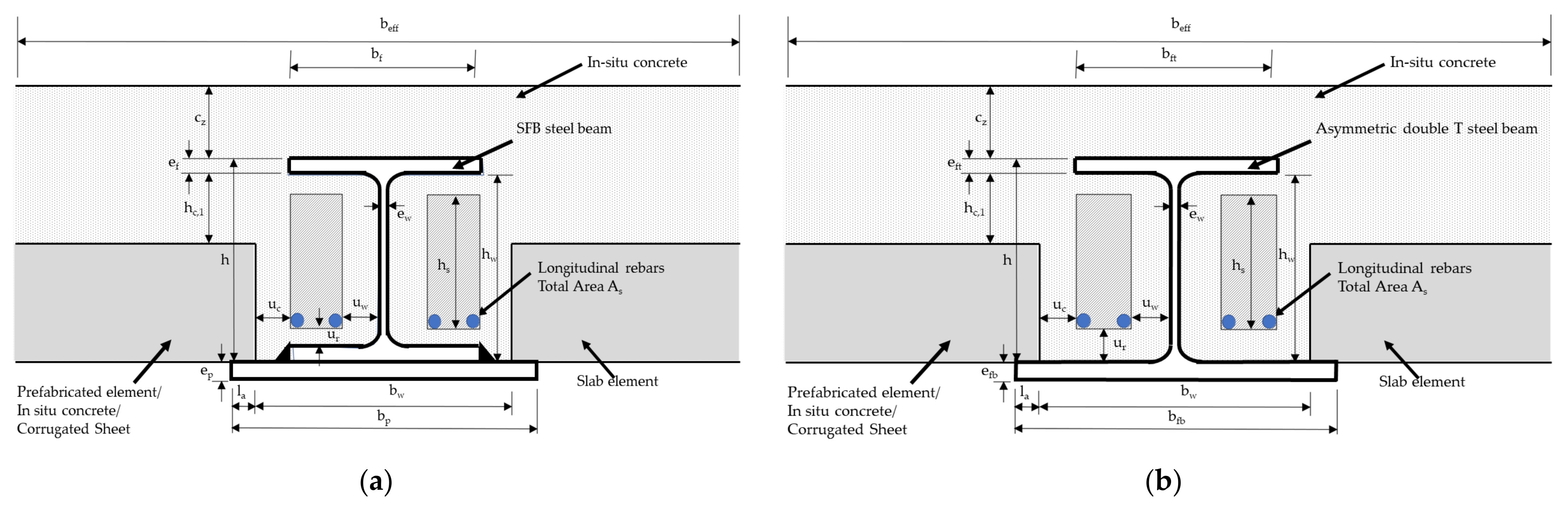
3.1. Presentation of the Simplified Design Method

The simplified method presented by Zanon et al. [21] was validated against SFB configurations, and was valid within the limits given in Table 1 and Table 2. The current study extends its scope of application to the asymmetric double-T cross-sections, as specified in Table 3. All the symbols from Table 2 and Table 3 are represented in Figure 9. In the following, the simplified method by Zanon et al. [21] is presented:
The method uses the following equation to compute the design moment resistance Mfi,t,Rd:
M fi , t , Rd = i = 1 n A i z i k y , θ , i f y , i γ M , fi , a + α slab j = 1 m A j z j k c , θ , j f c , j γ M , fi , c
  • zi, zj is the distance from the plastic neutral axis to the centroid of the area Ai or Aj
  • fy,i is the nominal yield strength;
  • fy, for the steel area Ai, (structural steel or reinforcement) taken as positive on the compression side of the plastic neutral axis and negative on the tension side—the reinforcement can be considered only in tension;
  • fc,j is the design strength of the concrete area Aj at 20 °C;
  • ky,θ,i and kc, θ,j are defined in Tables 3.2 and 3.3 of EN 1994-1-2 [27];
  • αslab is the coefficient considering the assumption of the rectangular stress block when designing slabs and shallow composite floor beams—αslab = 0.85.
The possible contribution of the concrete below the upper flange of the steel section should be neglected in the calculation, and thus only the concrete above the upper flange is considered. The design value of the concrete compression force can be calculated using the following equation:
N fi , c , Rd = f c γ M , fi , c b eff c z k h N fi , t , Rd = i = 1 n A i k y , θ , i f y , i γ M , fi , a
where:
  • kh = 0.85 for cz/h > 0.4
  • kh = 1.0 for all other cases
The width of the bottom flange is reduced to a value bfb,eff,fi using Equation (3), as follows:
b fb . eff . fi = max b ft   ; b fb 2 l a + e fb k c
where:
  • kc = 0.5 for a solid slab that covers 100% of the upper surface of the welded plate
  • kc = 1.0 for all other cases
Based on Zaharia and Franssen [15], the temperature θfb of the bottom flange can be assumed constant and is calculated using Equation (4):
Θ fb = A i e fb 2 + B i e fb + C i
where:
The temperature of the profile web θw is assumed constant and is calculated using Equation (5), based on Zaharia and Franssen [15]:
Θ w = A w ln   e fb + B w e C w ln e fb + D w h w 40
where:
In this equation, efb and hw are expressed in [mm].
Within the field of application of slim floor beams, the upper flange can be assumed as non-affected by the fire exposure.
For the longitudinal reinforcement placed within the zone determined by hs and uc, uw, ur according to Figure 9, the temperature θr can be calculated using the equation, based on Hanus et al. [16]:
Θ r = A r u eq 2 + B r u eq + C r
where:
  • Ar, Br, and Cr are given in Table 4 [16];
  • efb and hw shall be expressed in [mm];
  • ueq is the equivalent distance, and is calculated with Equation (7):
    u eq = min ( 45 mm , 25 mm + e fb 2 ) + 5 mm k c

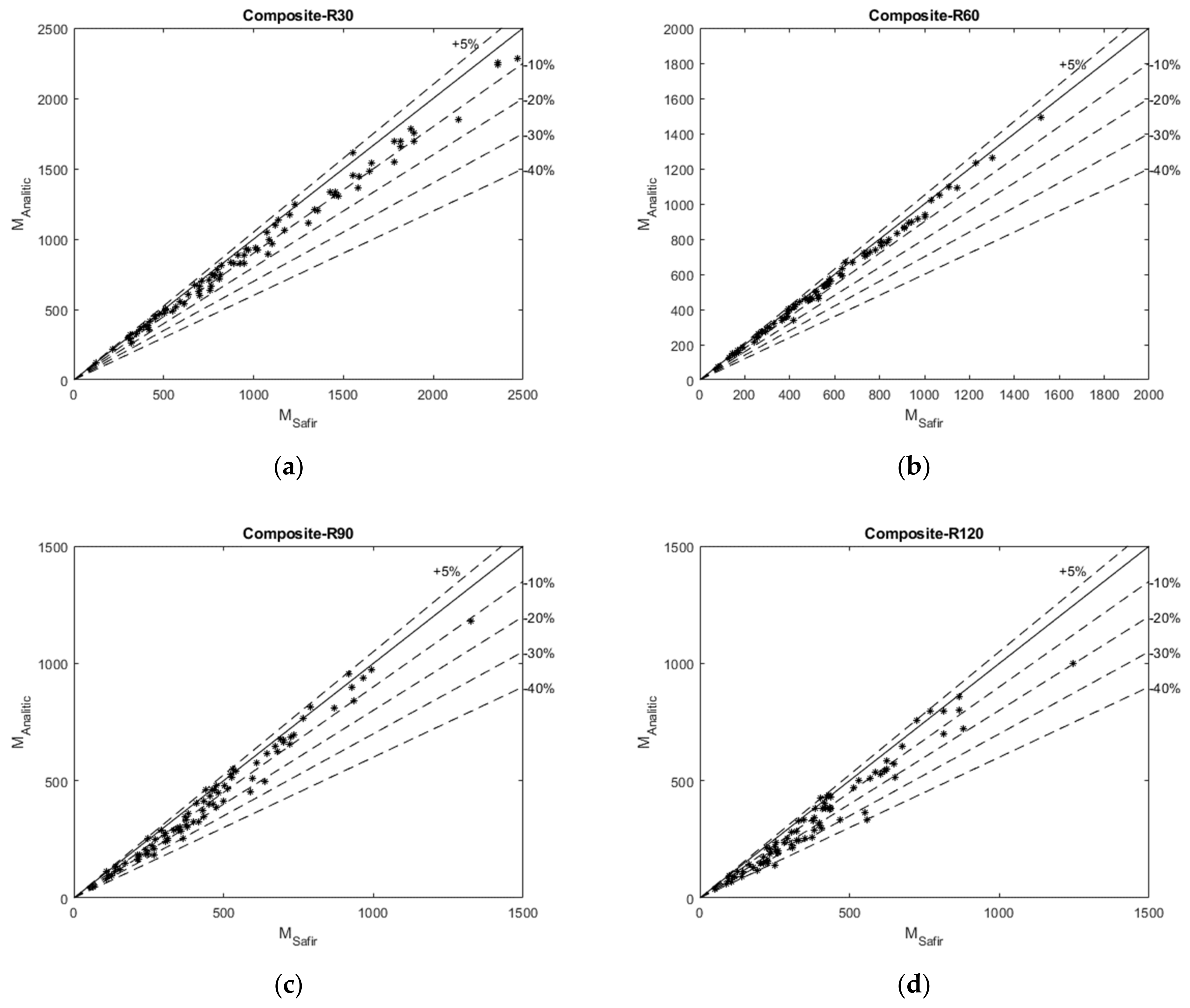
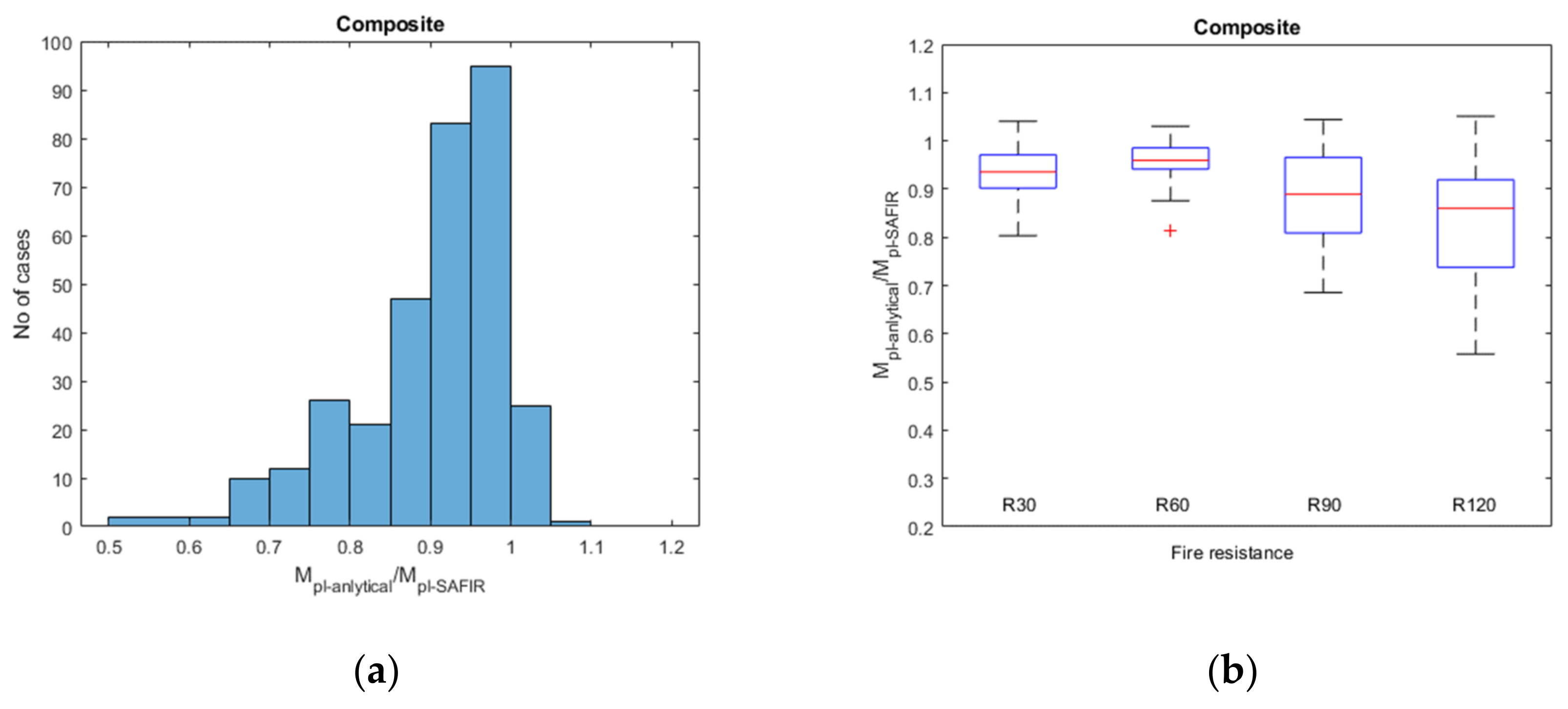
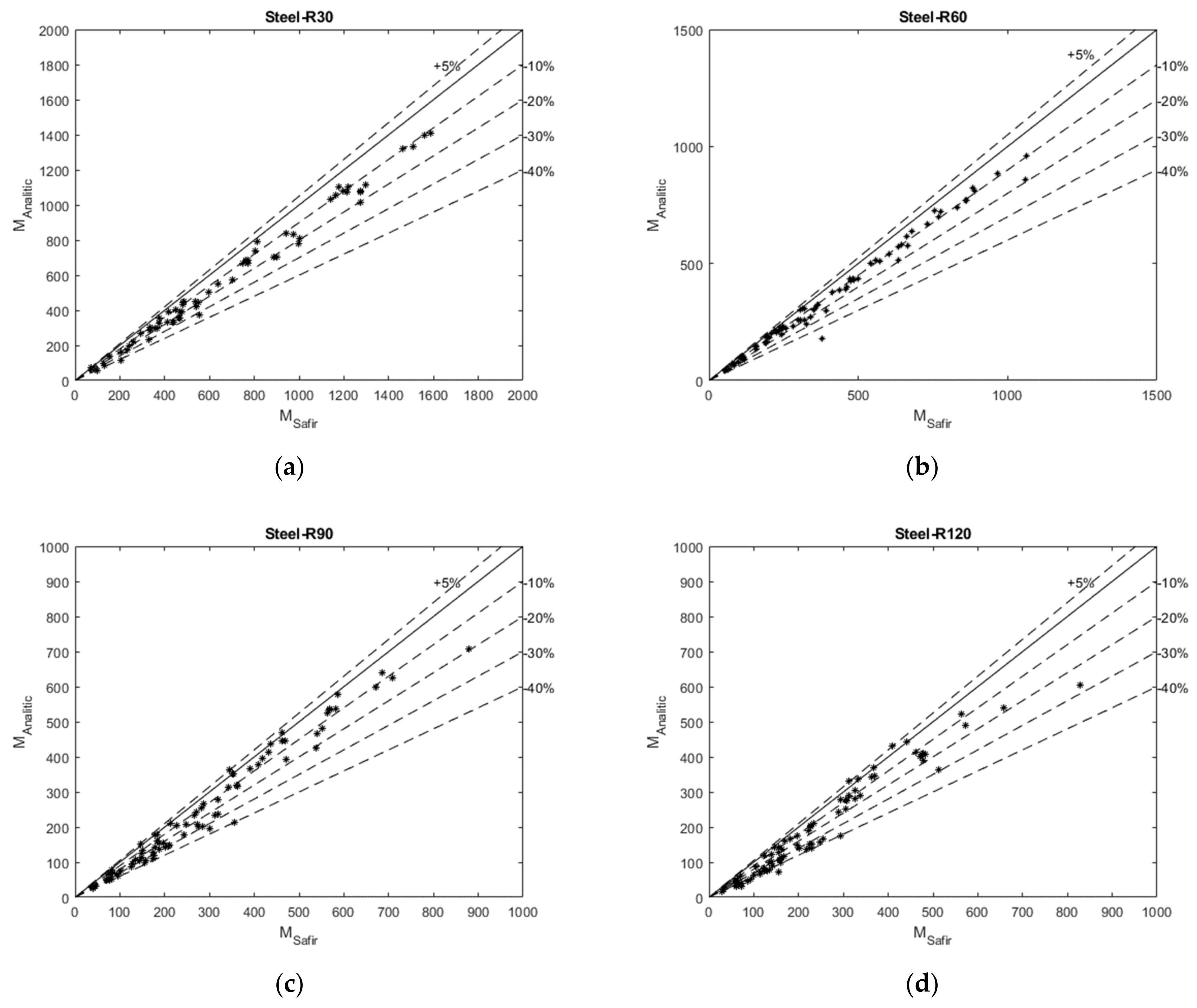
3.2. Parametric Study on Asymmetric Double-T Cross-Section

We considered 81 geometrical configurations of asymmetric slim beam cross-sections (Table 5), using the numerical model validated in Section 2. Four types of asymmetric double-T steel profile were assessed, as shown in Figure 3 (ASB type, welded steel cross-section, IFB type, and SB type). Each geometrical configuration was considered twice, with composite and non-composite behavior. For all cases, the model was evaluated for four different fire resistances (R30, R60, R90, R120) resulting in a total of 648 analyses. The varying parameters are explained in Table 5, using the notations from Figure 9b. The ranges proposed by Zanon et al. [21], presented in Table 2, were respected and even extended as shown in Table 3.
The bending resistance was determined numerically, considering a simply supported beam with a uniform load. The value of the applied load was determined in order to obtain the requested fire resistance demand of 30, 60, 90, or 120 min.
The simplified method has been applied in all 648 cases. The results obtained analytically were compared against the numerical results, in terms of bending resistance, for composite (Figure 10 and Figure 11) and non-composite behavior (Figure 12 and Figure 13). Figure 10 shows the comparison of composite behavior configurations, for R30 (a), R60 (b), R90 (c), and R120 (d), respectively. Figure 12 shows the comparison of non-composite behavior configurations, for R30 (a), R60 (b), R90 (c), and R120 (d), respectively.
As Figure 10 and Figure 12 suggest, the considered configurations cover a large interval of bending resistance values. The simplified method offers good results in comparison with the numerical values. The results obtained for R30 are underestimated by the simplified method up to 15%, due to the concrete thickness simplification, i.e., only the concrete thickness above the top flange is taken into consideration, while the plastic neutral axis is still in the steel profile height. The results obtained for R60 provide the closest results (up to 10%), as the PNA is close to the interface between the top steel flange and the concrete topping. The values for R90 and R120 demonstrate higher differences compared to the numerically results (up to about 30%, 40%, respectively), due to the simplification made to the temperature on the steel profile web which, in the simplified method, is considered to be uniform throughout the height. In the original equation of Zaharia and Franssen [15], the temperature in the web was calculated considering the distance along the height of the web measured from the top of the bottom flange. In Zanon et al.’s [21] method, a simplification was considered in the original equation, i.e., the temperature was determined only for the distance equal to a quarter of the web height and it was applied to the whole web. For R30 and R60, at this location, in many cases, the temperature does not exceed 400 °C. According to EN 1993-1-2 [25], at this level of temperature the streel strength remains unaffected. The situation is different in the cases of R90 and R120, as the temperature along the web is substantially increased, in particular in the lower part of the web. This is the reason why the simplified method leads to conservative values for longer fire exposures, up to a difference of about 40%.
The ratio between the bending resistance computed with the simplified method and the values obtained with SAFIR is analyzed in Figure 11, for composite behavior and in Figure 13, for non-composite behavior, respectively, while Figure 14 shows the results of all situations. Figure 11a, show the Gaussian curve of the studied data, and Figure 11b, Figure 13b and Figure 14b show a boxplot assessment. It can be noted from Figure 14b that the median value of the data is 0.933, for composite behavior cases and 0.853, for non-composite behavior. The first quartile is 0.86 (25% of the values are below 0.86), for composite behavior and 0.722 for non-composite behavior cases. The third quartile is 0.97 (75% of the values are below 0.97), for composite behavior, and 0.905 for non-composite behavior. For 95% of cases (613 configurations) the simplified method offered a ratio less or equal to 1. For the remaining 5% of cases (35 configurations), the computed bending moment was higher than that obtained with SAFIR, with a maximum ratio of 1.05.

4. Conclusions

A simplified approach for the design of slim floor systems under fire conditions was recently proposed by Zanon et al. [21], based on models existing in the literature. The method was validated through a comprehensive analysis of tests and a broad parametric study, but only for SFB type slim floor beams.
The scope of application of this method was extended in this paper, for other types of asymmetric double-T steel sections (without a welded plate below), as well as for extended geometric limits. This was done by means of a parametrical study, comprising 162 configurations, assessed for fire resistances R30, R60, R90 and R120, resulting in 648 analyses carried out with SAFIR software. The numerical model was validated considering composite and non-composite behavior against two corresponding experimental tests available in the literature.
The design moment resistance of the studied configurations was determined both numerically and analytically, using the simplified method, and showed good agreement. The best similitude between the results in terms of moment resistance was obtained for R60, the difference being below 10%.
The study demonstrated that the simplified method can cover a larger range of configurations, for both SFB and asymmetric double-T types, and may represent a strong tool for the fire design of slim floor beams.

Author Contributions

Conceptualization, D.D., R.Z. and F.H.; Data curation, D.D. and F.H.; Formal analysis, D.D.; Investigation, D.D. and F.H.; Methodology, R.Z. and F.H.; Project administration, F.H.; Software, D.D., D.P. and F.H.; Supervision, R.Z.; Validation, D.D.; Visualization, D.D. and I.B.; Writing—original draft, D.D.; Writing—review and editing, I.B. All authors have read and agreed to the published version of the manuscript.

Funding

This research did not receive external funding.

Institutional Review Board Statement

Not applicable.

Informed Consent Statement

Not applicable.

Conflicts of Interest

The authors declare no conflict of interest.

References

  1. Beall, C. Masonry Design and Detailing, 5th ed.; McGraw-Hill Professional: New York, NY, USA, 2004. [Google Scholar]
  2. Zahrai, S.M. Experimental study of typical and retrofitted jack arch slabs in a single story 3D steel building. Int. J. Civ. Eng. 2015, 13, 278–288. [Google Scholar]
  3. Maheri, M.R.; Rahmani, H. Static and seismic design of one-way and two-way jack arch masonry slabs. Eng. Struct. 2003, 25, 1639–1654. [Google Scholar] [CrossRef]
  4. Ahmed, I.M.; Tsavdaridis, K.D. The evolution of composite flooring systems: Applications, testing, modelling and eurocode design approaches. J. Constr. Steel Res. 2019, 155, 286–300. [Google Scholar] [CrossRef]
  5. PEIKKO GROUP. DELTABEAM® Composite Beams Slim Floor Structure with Integrated Fireproofing. Tech. Man. 2021. Available online: https://www.peikko.com/products/product/deltabeam-product-information/ (accessed on 1 November 2021).
  6. Peltonen, S.; Leskela, M. Connection Behaviour of a Concrete Dowel in a Circular Web Hole of a Steel Beam. In Composite Construction in Steel and Concrete V; ASCE: Reston, VA, USA, 2006; pp. 544–552. [Google Scholar]
  7. ArcelorMittal Commercial Sections. Slim Floor, an Innovative Concept for Floors; Long Carbon Europe Sections and Merchant Bars: Esch-sur-Alzette, Luxembourg, 2008; Available online: https://sections.arcelormittal.com/repository2/Sections/5_5_1_SlimFloor.pdf (accessed on 1 November 2021).
  8. Huo, B.Y.; D’Mello, C.A. Push-out tests and analytical study of shear transfer mechanisms in composite shallow cellular floor beams. J. Constr. Steel Res. 2013, 88, 191–205. [Google Scholar] [CrossRef]
  9. Ju, Y.K.; Chun, S.C.; Kim, D.Y.; Kim, D.H.; Kim, S.D.; Chung, K.R. Structural performance of I-TECH composite beam steel with web openings. CIB-CTBUH Int. Conf. Tall Build. CIB Rep. 2003, 411–418. [Google Scholar]
  10. Ju, Y.K.; Chun, S.C.; Kim, S.D. Flexural test of a composite beam using asymmetric steel section with web openings. J. Struct. Eng. 2009, 135, 448–458. [Google Scholar] [CrossRef]
  11. Ju, Y.K.; Kim, D.H.; Kim, S.D. Experimental assessment of the shear strength of an asymmetric steel composite beam with web openings. Can. J. Civ. Eng. 2005, 32, 314–328. [Google Scholar] [CrossRef]
  12. BritishSteel Sections—Asymmetric Beams. Available online: https://britishsteel.co.uk/media/365485/british-steel-asymmetric-beams-datasheet.pdf (accessed on 20 September 2021).
  13. The Steel Construction Institute (SCI). Slimflor Compendium; SCI: Berkshire, UK, 2008. [Google Scholar]
  14. Fontana, M.; Borgogno, W. Slim Floor slabs: Fire resistance and system behaviour of hollow core slabs on flexible beams. In Proceedings of the Composite Construction in Steel and Concrete, Engineering Foundation Conference; ASCE: Irsee, Germany, 1996. [Google Scholar]
  15. Zaharia, R.; Franssen, J.M. Simple equations for the calculation of the temperature within the cross-section of slim floor beams under ISO Fire. Steel Compos. Struct. 2012, 13, 171–185. [Google Scholar] [CrossRef]
  16. Hanus, F.; Zaganelli, D.; Cajot, L.-G.; Braun, M. Analytical methods for the prediction of fire resistance of “reinforced” slimfloor beams. In Proceedings of the 8th European Conference on Steel and Composite Structures, Copenhagen, Denmark, 13–15 September 2017. [Google Scholar]
  17. CEN European Committee for Standardization: EN 1992-1-2: Eurocode 2—Design of Concrete Structures. Part 1-2. General Rules—Structural Fire Design, CEN, Brussels. 2005. Available online: https://www.phd.eng.br/wp-content/uploads/2015/12/en.1992.1.2.2004.pdf (accessed on 1 November 2021).
  18. Cajot, L.-G. Simplified design methods for slim floor beams exposed to fire. In Proceedings of the 12th NordicSteel Construction Conference, Oslo, Norway, 5–7 September 2012. [Google Scholar]
  19. Romero, M.; Cajot, L.-G.; Conan, Y.; Braun, M. Fire design methods for slim-floor structures. Steel Constr. 2015, 8, 102–109. [Google Scholar] [CrossRef]
  20. Romero, M.L.; Albero, V.; Espinós, A.; Hospitaler, A. Fire design of slim-floor beams. Stahlbau 2019, 88, 665–674. [Google Scholar] [CrossRef]
  21. Zanon, R.; Yildiz, S.; Obiala, R.; Braun, M. Shallow composite floor beams—Proposal of a simplified analytical method for standard fire rating. ce/papers 2021, 4, 1325–1334. [Google Scholar] [CrossRef]
  22. Franssen, J.M. Safir—A thermal/structural program modelling structures under fire. Eng. J. 2005, 42, 143–158. [Google Scholar]
  23. Wainman, D.E. BS 476: Part 21 Fire Resistance Tests Summary of Data Obtained during a Test on a Composite Slim Floor Beam 7 April 1996; Test Number WFRC 44174, Technical Note; British Steel Pic—Swinden Technology Centre: Rotherham, UK, 1996. [Google Scholar]
  24. Wainman, D.E. Preliminary Assessment of the Data Arising from a Standard Fire Resistance Test Performed on a Slimflor Beam at the Warrington Fore Research Centre on 14 February 1996; Test Number WFRC 66162, Technical Note; British Steel Pic—Swinden Technology Centre: Rotherham, UK, 1996. [Google Scholar]
  25. CEN European Committee for Standardization: EN 1993-1-2, Eurocode 3: Design of Steel Structures—Part 1-2: General Rules—Structural Fire Design, Brussels. 2005. Available online: https://www.gaprojekt.com/sites/default/files/legislation/Eurocode%203%20-Design%20of%20steel%20structures%20-%20Part%201-2%20-%20en.1993.1.2.2005.pdf (accessed on 1 November 2021).
  26. CEN European Committee for Standardization: EN 1991-1-2, Eurocode 1: Actions on Structures—Part 1-2: General Actions—Actions on Structures Exposed to Fire, Brussels. 2004. Available online: https://www.phd.eng.br/wp-content/uploads/2015/12/en.1991.1.2.2002.pdf (accessed on 1 November 2021).
  27. CEN European Committee for Standardization: EN 1994-1-2, Eurocode 4: Design of Composite Steel and Concrete Structures—Part 1-2: General Rules—Structural Fire Design, Brussels. 2005. Available online: https://www.phd.eng.br/wp-content/uploads/2015/12/en.1994.1.2.2005.pdf (accessed on 1 November 2021).
  28. Duma, D.; Zaharia, R.; Pintea, D.; Both, I. Numerical model validation of non-composite slim floor beam subjected to fire. In Proceedings of the International Scientific Conference CIBv-Civil Engineering and Building Services, Brasov, Romania, 4–5 November 2021. [Google Scholar]
Figure 1. Asymmetrical slim floor beam: (a) with a wider plate welded below the bottom flange slim floor beam (SFB); (b) with a wider bottom flange integrated floor beam (IFB) [7].
Applsci 12 00574 g001
Figure 2. Composite slim floor beam (CoSFB) with dowel reinforcement–composite behavior [7].
Applsci 12 00574 g002
Figure 3. Asymmetric double-T steel cross sections as slim floor beams: (a) ASB; (b) welded; (c) IFB; (d) SB.
Applsci 12 00574 g003
Figure 4. Cross-section of the experimental test configuration: (a) WRFC 44174 [23]; (b) WFRC 66162 [24].
Applsci 12 00574 g004
Figure 5. Cross-section of the WFRC 44174 test.
Applsci 12 00574 g005
Figure 6. Cross-sections of the WFRC 66162 test: (a) cross-section F with a thinner concrete slab depth [28]; (b) transition cross-section; (c) cross-section G with a concrete slab standing on the lower flange of the steel profile [28].
Applsci 12 00574 g006
Figure 7. Temperature comparison between the numerical model and the experiment for: (a) WFRC 44174; (b) WFRC 66162 [28].
Applsci 12 00574 g007
Figure 8. Vertical displacement at mid-span: comparison between numerical model and experiment: (a) WFRC 44174; (b) WFRC 66162 [28].
Applsci 12 00574 g008
Figure 9. (a) SFB [21] and (b) asymmetric double-T cross-section with notation.
Applsci 12 00574 g009
Figure 10. Comparison of bending resistance for composite behavior of studied configurations—analytical model vs. finite element model (FEM): (a) R30; (b) R60; (c) R90; (d) R120.
Applsci 12 00574 g010
Figure 11. Assessment of the studied configurations with composite behavior: (a) Gauss curve, (b) boxplot assessment.
Applsci 12 00574 g011
Figure 12. Comparison of bending resistance for non-composite behavior of studied configurations—analytical model vs. FEM: (a) R30; (b) R60; (c) R90; (d) R120.
Applsci 12 00574 g012
Figure 13. Assessment of the studied configurations with non-composite behavior: (a) Gauss curve; (b) boxplot assessment.
Applsci 12 00574 g013
Figure 14. Assessment of the reliability level for all 680 configurations: (a) Gauss curve, (b) boxplot assessment.
Applsci 12 00574 g014
Table 1. Application range—general scope [21].
CriteriaRange
Maximum span12 m
Cross-section class1 and 2
Slab typeComposite slab with steel sheeting
Solid concrete slab
Prefabricated slab with in-situ concrete
Steel gradeS235 to S460
Concrete classC20/25 to C50/60
Reinforcement barsDiameter 6 to 32 mm
B500B/C
Table 2. Application range—geometric limits for SFB type [21].
Steel ProfileConcrete SlabReinforcement
10 ≤ ep ≤ 4030 ≤ cz ≤ 150ur ≥ 30
8 ≤ ef ≤ 40hc.1 ≥ 20uc ≥ 40
0.7 ≤ ep/ef ≤ 2la ≥ 40uw ≥ 40
6 ≤ ew ≤ 30bf + 60 ≤ bwhs ≤ hw−2 × ur
160 ≤ h ≤ 450 As ≤ 0.5 bp × ep
160 ≤ bf ≤ 450 As ≤ 5% × bw × (h + cz)
160 ≤ bp-bf ≤ 250 As ≤ 2 × beff × cz × (fck/fsk)
All values are expressed in [mm].
Table 3. Application range—Geometric limits for asymmetric double-T type.
Steel ProfileConcrete SlabReinforcement
12 ≤ efb ≤ 4030 ≤ cz ≤ 150ur ≥ 25
10 ≤ eft ≤ 40hc.1 ≥ 20uc ≥ 30
0.7 ≤ efb/ef ≤ 2.4la ≥ 40uw ≥ 30
6 ≤ ew ≤ 30bf + 60 ≤ bwhs ≤ hw−2 × ur
135 ≤ h ≤ 450 As ≤ 0.5 bfb × efb
160 ≤ bfb ≤ 500 As ≤ 5% × bw × (h + cz)
110 ≤ bfb-bft ≤ 250 As ≤ 2 × beff × cz × (fck/fsk)
All values are expressed in [mm].
Table 4. Coefficients for the simplified analytical method [15,16].
CoefficientR30R60R90R120
Ai0.1130.13000
Bi−12.80−11.80−2.60−1.25
Ci7609809901025
Aw−140.70−103.80−108.60−70.44
Bw832.42968.601146.701124.40
Cw0.03170.02320.01980.0158
Dw−0.230−0.182−0.154−0.134
Ar00.09540.05480.0381
Br0−19.254−15.130−12.797
Cr3001105.41135.91138.1
Table 5. The evaluated geometrical configurations.
Steel Profile TypeSlab Type 1h [mm]bfb [mm]bft [mm]efb [mm]eft [mm]ew [mm]cz [mm]L [m]l [m]SteelConcreteReinforcement
No of BarsΦ [mm]uw [mm]ur [mm]
ASB22582851751414106091.5S355C50/6042537.532.5
ASB22582851751414109091.5S460C30/3742537.542.5
ASB22582851751414106091.5S235C25/300---
ASB225828517514141012091.5S355C50/604164232
ASB22582851751414106091.5S235C50/602205030
ASB12582851751414109091.5S460C30/3742537.542.5
ASB12582851751414106091.5S355C50/6022547.532.5
ASB12582851751414106091.5S460C40/500---
ASB22663001902222254082S275C30/370---
ASB226630019022222512082S235C50/600---
ASB22663001902222256082S355C30/3722537.532.5
ASB226630019022222512082S460C25/300---
ASB22663001902222254082S275C50/602204030
ASB126630019022222512082S235C50/600---
ASB126630019022222512082S275C30/3722537.537.5
ASB126630019022222512082S460C35/450---
ASB12663001902222259082S235C25/3022522.537.5
ASB13022931834040204092S355C30/3722547.527.5
ASB13022931834040206092S235C50/6022547.527.5
ASB13022931834040204092S235C30/374322934
ASB13022931834040204091.5S460C30/370---
ASB23022931834040204092S355C50/6042532.532.5
ASB23022931834040204092S235C25/302165232
ASB23022931834040204092S460C40/5022547.532.5
ASB230229318340402012092S235C30/3722547.542.5
Welded122050028020201080102.25S235C25/304203530
Welded122050028020201080102.25S460C30/3742532.527.5
Welded122050028020201040102.25S355C40/504203530
Welded1220500280202010120102.25S275C25/304203530
Welded122050028020201040102.25S235C25/300---
Welded222050028016161080102.25S355C25/304203530
Welded222050028020201080102.25S235C40/504203540
Welded222050028020201080102.25S460C35/4542532.527.5
Welded222050028020201080102.25S275C30/374203535
Welded222050028020202080102.25S235C35/4542532.527.5
IFB213527013510.2156.612561.5S355C30/374203025
IFB213527013510.2206.612561.5S235C30/372203025
IFB213527013510.2126.612561.5S460C50/604203025
IFB213527013510.2156.64061.5S355C30/374203025
IFB213527013510.2206.64061.5S355C50/604203025
IFB213527013510.2126.64061.5S235C30/372203025
IFB213527013510.2206.64061.5S460C25/304203025
IFB122540019014.6259.460112.5S460C35/4542537.532.5
IFB122540019014.6159.460112.5S460C50/6022537.542.5
IFB122540019014.6259.460112.5S355C25/3042537.532.5
IFB122540019014.6359.4120112.5S275C35/454164252
IFB122540019014.6259.4120112.5S235C35/454323429
IFB122540019014.6259.4100112.5S460C25/3022537.532.5
IFB122540019014.6159.440112.5S355C50/604204035
IFB222540019014.6359.460112.5S235C35/4522537.532.5
IFB222540019014.6159.460112.5S355C25/304164247
IFB222540019014.6259.4100112.5S235C50/604323439
IFB222540019014.6259.440112.5S355C35/4542537.532.5
IFB218032017012.72084082S275C50/6022537.537.5
IFB218032017012.720812082S235C30/3722537.542.5
IFB218040017012.71586082S355C25/342537.537.5
IFB218032017012.720812082S460C50/604204045
IFB218032017012.72584082S275C50/602323434
IFB118040017012.720812082S235C30/374164232
IFB118032017012.730812082S275C50/6022537.537.5
IFB118032017012.720812082S460C40/5022537.537.5
IFB118040017012.72089082S460C50/604204040
IFB118040017012.72089082S235C50/604144237
SB2376300180242413.540123S460C40/5042537.547.5
SB2376300180242413.540123S355C25/300---
SB2376300180242413.580123S460C50/604323444
SB2376300180242413.5120123S275C30/3742537.547.5
SB2376300180242413.540123S355C40/504204040
SB1376300180242413.580123S460C25/302323444
SB1376300180242413.540123S235C50/6022537.547.5
SB1376300180242413.5150123S355C30/372204050
SB23013102003939214081.5S355C50/6042537.537.5
SB23013102003939214081.5S275C25/3022537.537.5
SB23013102003939214081.5S235C50/604323439
SB23013102003939216081.5S355C30/372164242
SB23013102003939214081.5S355C40/5042537.532.5
SB23013102003939218081.5S460C50/6042537.537.5
SB13013102003939217081.5S235C50/602323434
SB130131020039392110081.5S460C40/504204040
SB13013102003939214081.5S355C25/3022537.537.5
1 Type No. 1 represents a prefabricated slab with in-situ concrete; Type No. 2 represents solid concrete slab.
Publisher’s Note: MDPI stays neutral with regard to jurisdictional claims in published maps and institutional affiliations.

