Article

Deducing of Optical and Electronic Domains Based Distortions in Radio over Fiber Network

1
Faculty of Information Technology, Beijing University of Technology, Beijing 100124, China
2
Department of Electrical Engineering, Qurtuba University of Science and IT, Dera Ismail Khan 29050, Pakistan
3
Engineering Research Center of Intelligent Perception and Autonomous Control, Faculty of Information Technology, Beijing University of Technology, Beijing 100124, China
4
Department of Computer Sciences, College of Computer and Information Sciences, Princess Nourah Bint Abdulrahman University, P.O. Box 84428, Riyadh 11671, Saudi Arabia
5
Department of Electrical Engineering, College of Engineering, Jouf University, Sakaka 72388, Saudi Arabia
6
Department of Electrical Engineering, University of Engineering Technology, Mardan 23200, Pakistan
7
Department of Electrical Engineering, International Islamic University, Islamabad 44000, Pakistan
8
School of Marine Science and Technology, Northwestern Polytechnical University, Xi’an 710600, China
*
Authors to whom correspondence should be addressed.
Submission received: 14 December 2021 / Revised: 4 January 2022 / Accepted: 10 January 2022 / Published: 12 January 2022
(This article belongs to the Special Issue 5G and Beyond Fiber-Wireless Network Communications)

Abstract

:
Managing the users multimedia and long-range based demands, the radio over fiber (RoF) mechanism has been introduced recently. RoF mingles the optical and radio communication frameworks to increase mobility and offer high capacity communication networks (CNs). In this paper, a full-duplex RoF-based CN is investigated for the next-generation passive optical network (PON), utilizing wavelength division multiplexing (WDM) technology. The desolations on account of optical and electronic domains (OEDs) are addressed, using dispersion compensation fiber (DCF) and optical and electrical filters, including modulation scheme. The analytical and simulation models are analyzed in terms of phase error (PE), radio frequency (RF), fiber length and input and received powers. The performance of the proposed model is successfully evaluated for 50 km range, −40 to −18 dBm received power, −20 to 0 dBm input power, where below 10 6 bit error rate (BER) is recorded. Thus, this signifies that the presented model exhibits smooth execution against OEDs impairments.

1. Introduction

The traffic on internet services has been increased exponentially in the last few years, and it is expected that the data rate demands will touch the zettabyte digit between 2022 to 2025 [1,2]. Therefore, a developed approach is required to support growing needs like propagation range and multimedia based data transmissions. Passive optical networks (PONs) are considered fruitful solutions for transmitting high capacity data with minimum bit error rate (BER). Furthermore, the installation of PONs is acceptable to the entire world for increasing speed and capacity to the users [3,4]. However, the wired based PONs contain extra issues like nonlinear impairments (NLIs) while transmitting high bandwidth data over fiber for long range, which badly disturbs the system flexibility [5]. On the other side, the physical-less based communication network (CN) presents accurate probability within the flexible environment; however, it fails to accommodate a considerable number of users with the high bandwidth capacity of long range transmission [6]. Thus, to overcome on NLIs and support above mentioned demands, the new approach named radio over fiber (RoF) links is developed, which combines the physical and physical-less setups of CNs [7,8,9,10]. Moreover, the wavelength division multiplexing (WDM) technology and advanced modulation schemes have developed the fidelity many times of the RoF system. This advanced methodology of CN minimizes the NLIs, and the system performance increases in terms of transmission range, number of users and capacity. In contrast, the RoF system uses the concept of electrical to optical (E/O) and visual to electrical (O/E) conversion procedures, which make space for the peak to average power ratio impairments (PAPRIs) [11,12]. Therefore, this paper investigates the novel WDM based RoF technology which aims to suppress the NLIs and PAPRIs.

1.1. Related Work

The RoF technology is considered a unique solution to design the CN healthier against NLIs and PAPRIs. Various researchers have already worked on NLIs and PAPRIs and made some productive solutions. Some of them are discussed as follows. In [13], authors have studied a novel adaptive RoF system for next-generation cloud radio access network, which goal is to maintain power consumption and to compensate NLIs. In [14], the authors have developed 2 × 2 multiple input multiple output based OFDM methodology for improving the RoF structure functionalities. An advanced WDM-RoF system is discussed in [15,16], where 0.45 nm are chosen for channel transmission with keeping constant the input power. The study in [17] explores multi-mode operation in RoF technology using multi-wavelength optical comb and pulse shaping. The 4QAM-OFDM procedure is applied before transmitting signals over WDM within a 5G carrier frequency. In [18], the authors have employed a cascaded in-pulse quadrature modulator and intensity modulator for D-band vector millimetre waves in the RoF system. Muramoto et al. in [19] have presented a graded-index plastic optical fiber technique for OFDM based RoF system to minimize noise and distortions. In [20], authors have demonstrated that an RF transmission system in S-band using 2 × 2 multi input multi output (MIMO)-OFDM with orthogonal and biorthogonal wavelets, employing phase shift keying (PSK) modulation format. In [21], Coelho et al. have proposed the OFDM based WDM RoF system by applying fiber brag grating (FBG).
However, these previously proposed solutions are limited to addressing NLIs and PAPRIs for long range transmission CNs. Moreover, these schemes require different costly carriers to transmit long distances with low BER data. In the existing models, the phase errors (PEs), NLIs and PAPRIs are not studied for RoF system, which have limited the high capacity fifth generation services. The enhancement in online services and long range range communication requirements, it is necessary to minimize the issues generated by PEs, NLIs and PAPRIs. Therefore, in this paper, based on PON, a full duplex RoF system is presented, using WDM technology to decrease the factors of NLIs and PAPRIs.

1.2. Major Contributions

This section shows that multimedia and transmission range demands are significant issues in today’s world. Secondly, High bandwidth capacity and long distance CNs include the issues like NLIs. The full duplex WDM-RoF CN also produces PAPRIs by reason of O/E and E/O conversions. The main objectives of this system are to manage the NLIs and PAPRIs, that ROF could transmit data up to a long range, including maximum capacity information. The primary goals of the proposed framework are listed as follows.
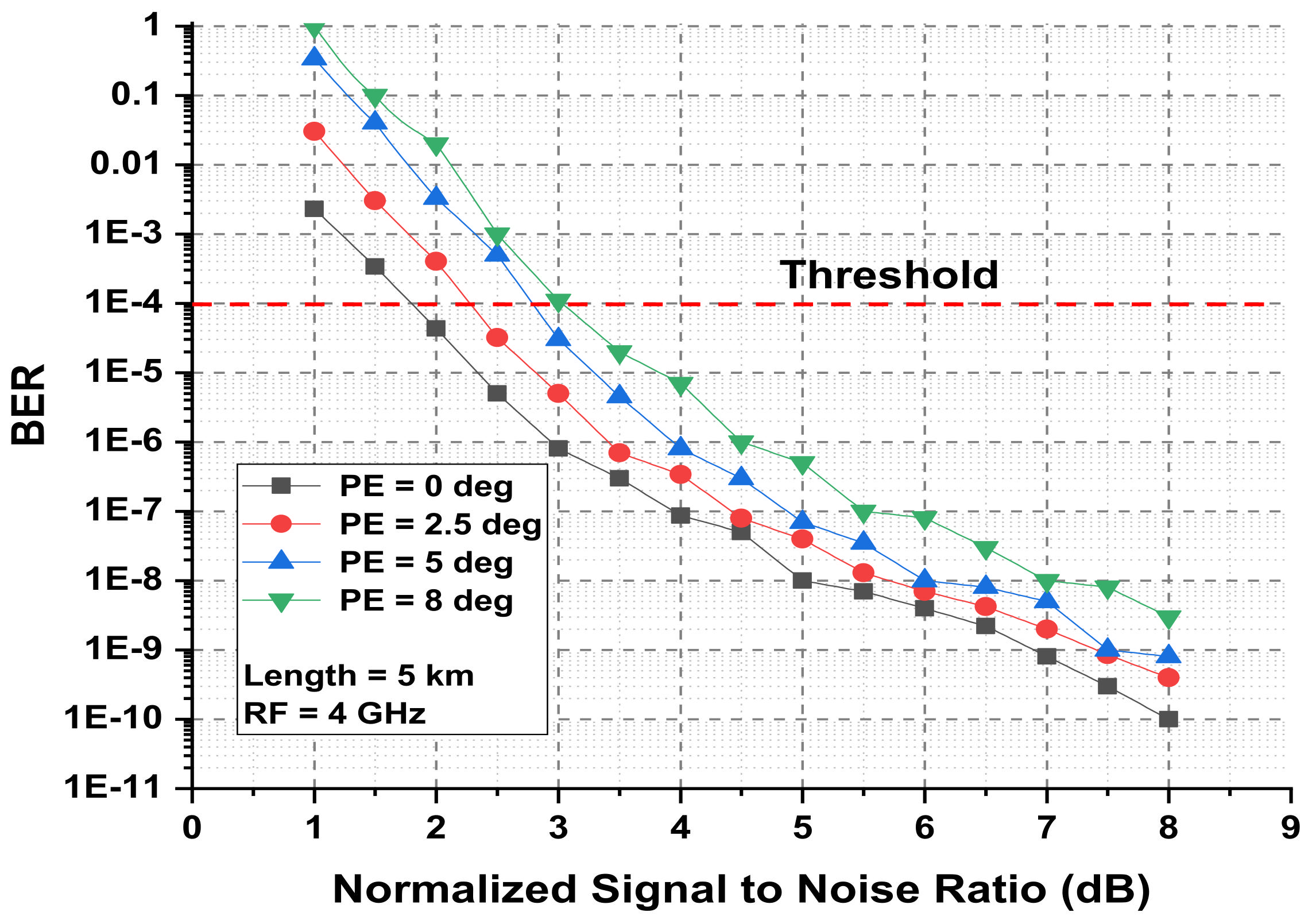
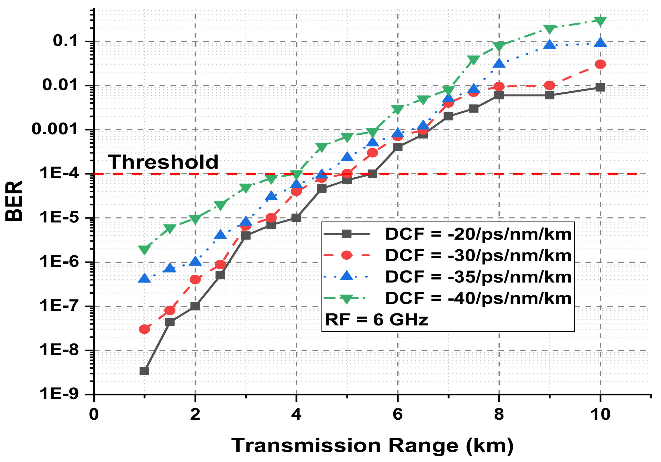
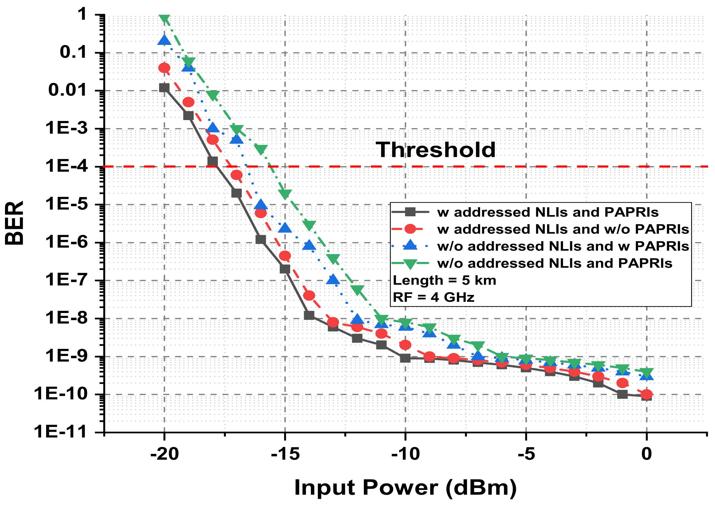
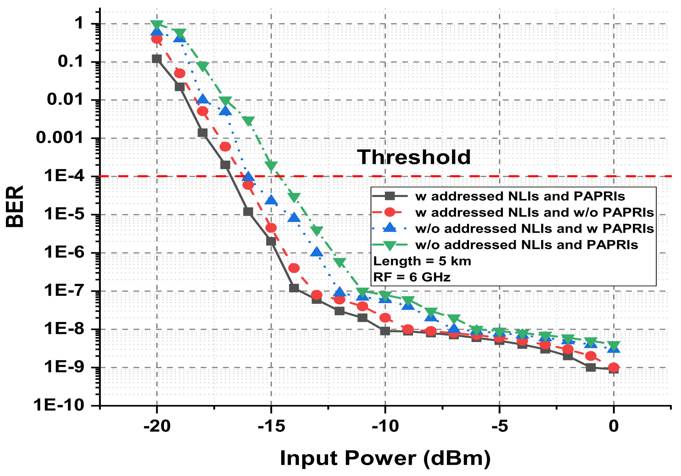
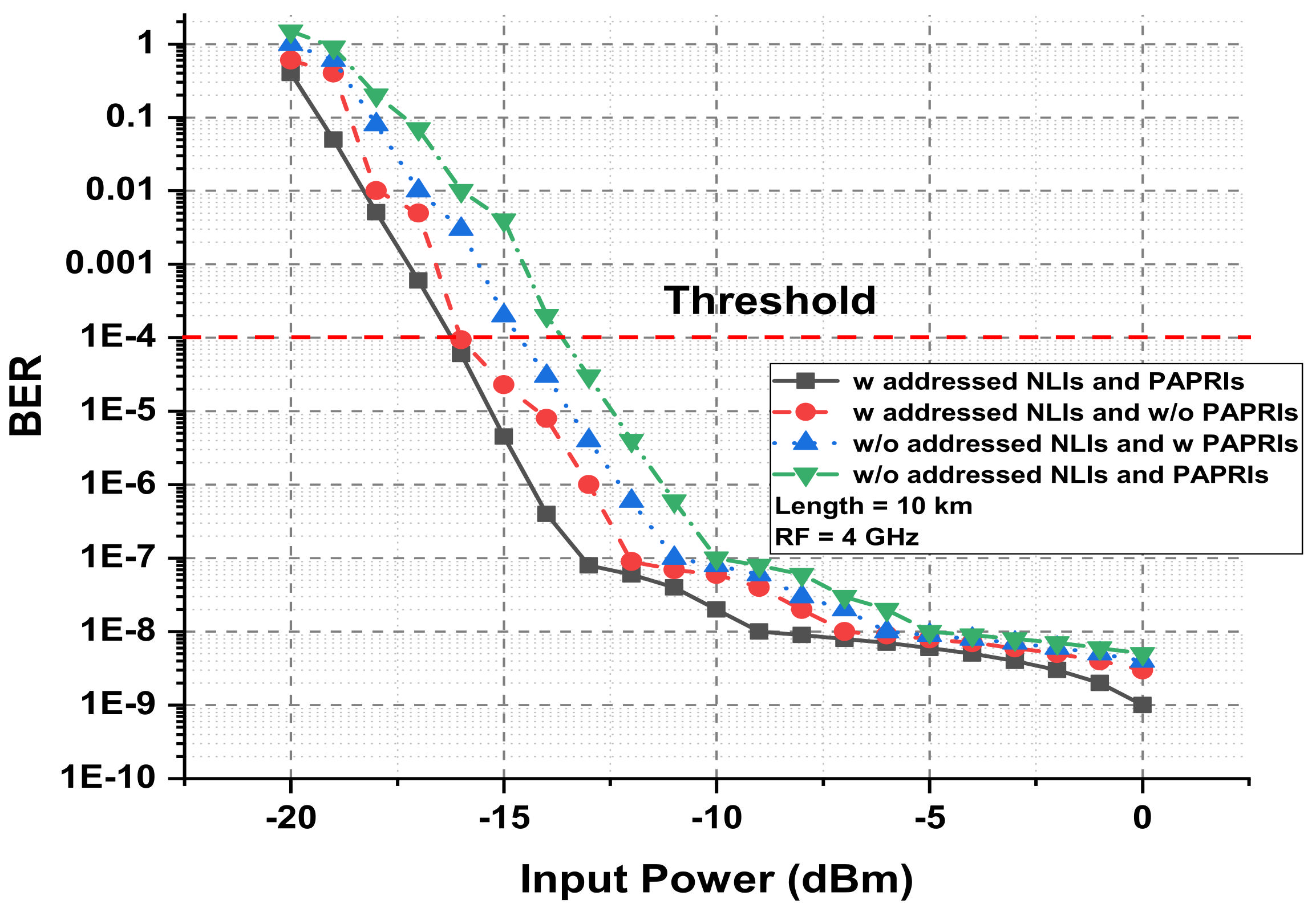
  • The techniques like balancing phase error (PE), dispersion compensation fiber (DCF), optical and electrical filters and full duplex RoF CN are applied for investigating and compensating the NLIs and PAPRIs.
  • The mathematical estimations are conducted for the above mentioned techniques aiming to enhance the accuracy of the proposed RoF system.
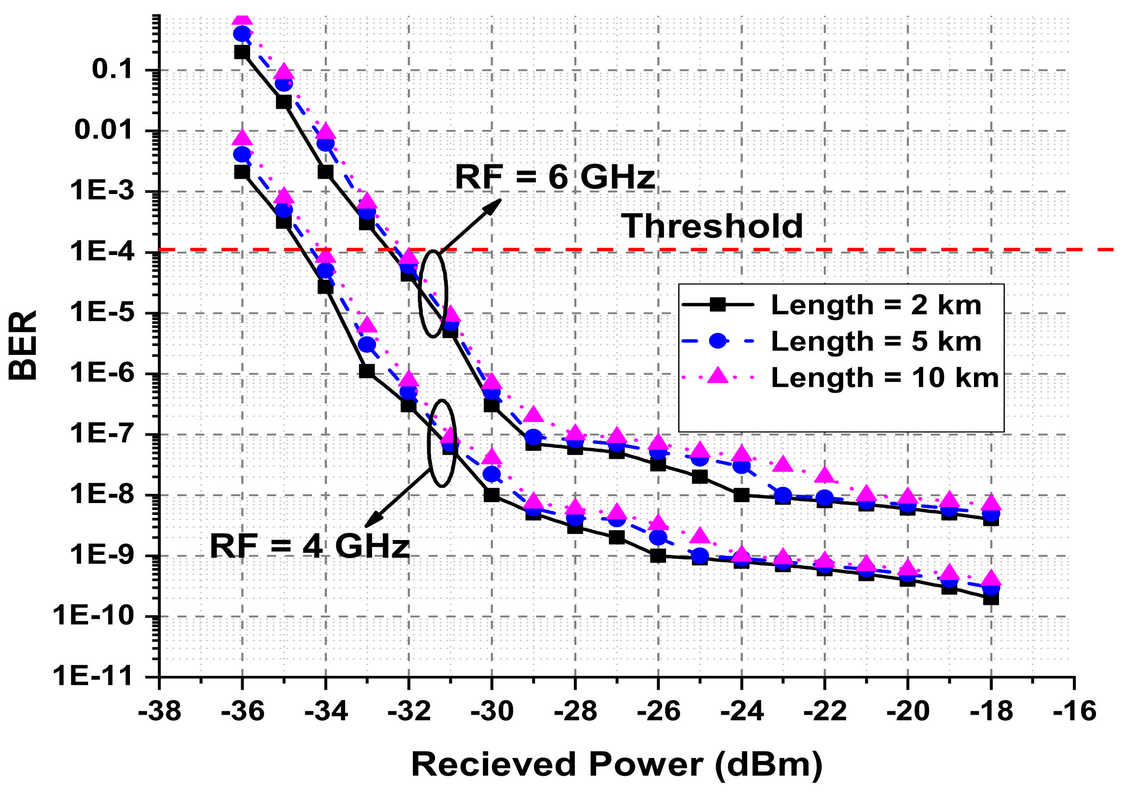
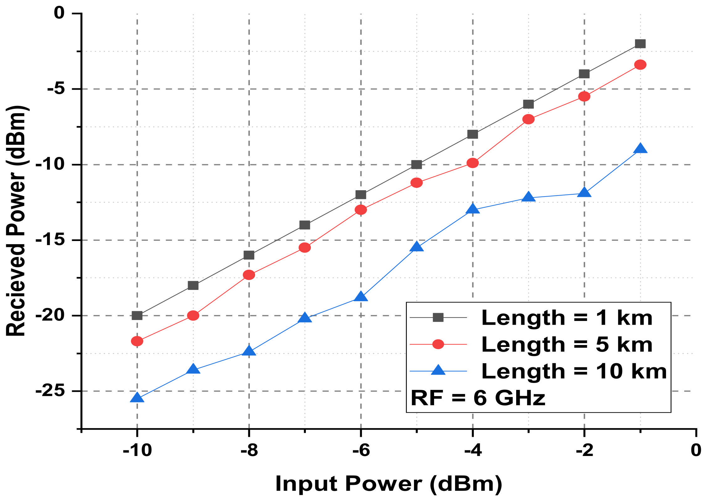
  • The simulation model is examined using the analytical approach in terms of laser power, received power, RF frequency, fibre length, and filters.
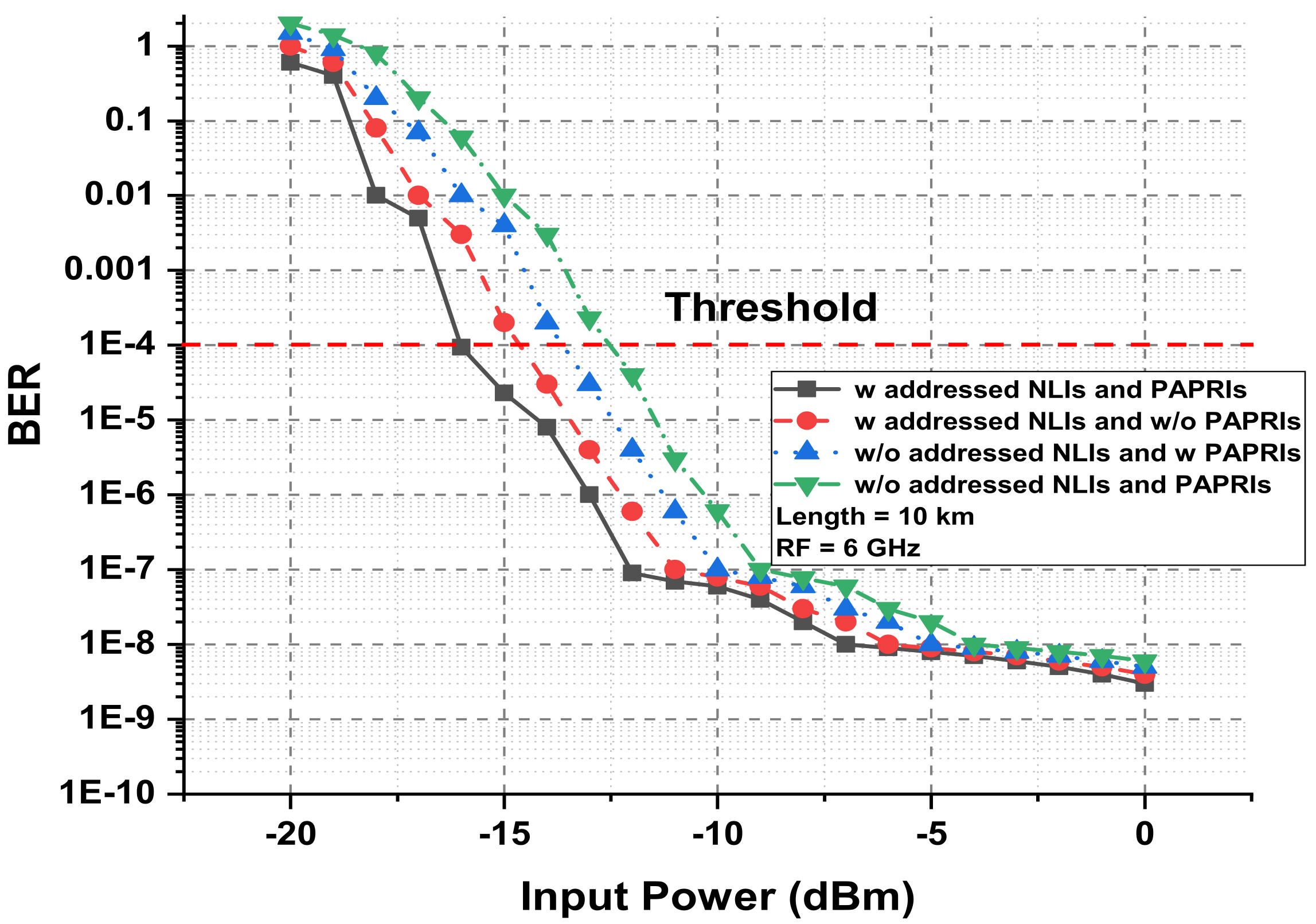
  • Two measuring parameters, bit error rate (BER) and normalized signal to noise ratio, are used to estimate the conduction of the proposed RoF model against PAPRIs, NLIs and PEs.
Following the introduction section, the rest of the paper includes the layout of the proposed model in Section 2, analytical modelling in Section 3, results and discussion of offered CN in Section 4 and conclusion of the proposed system in Section 5.

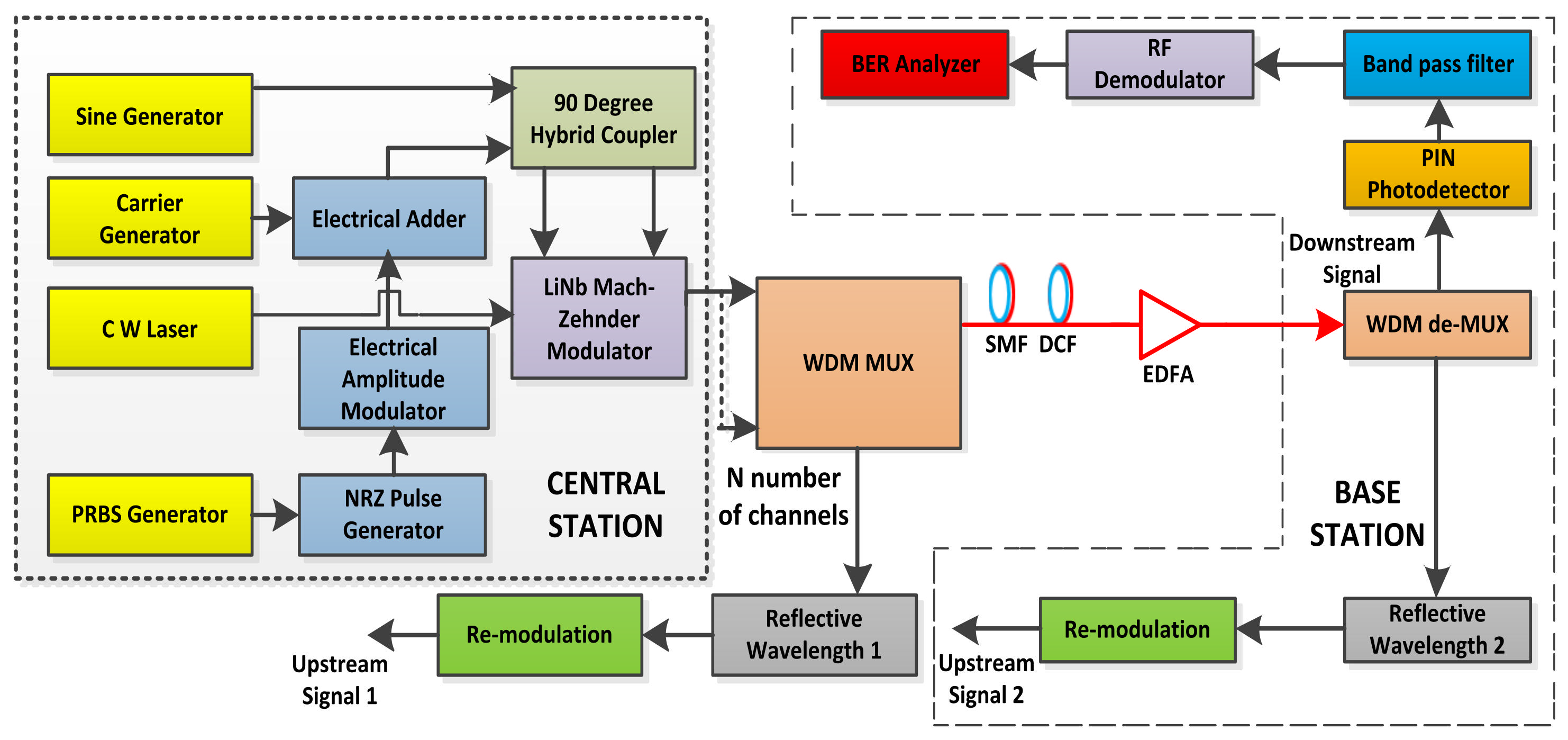
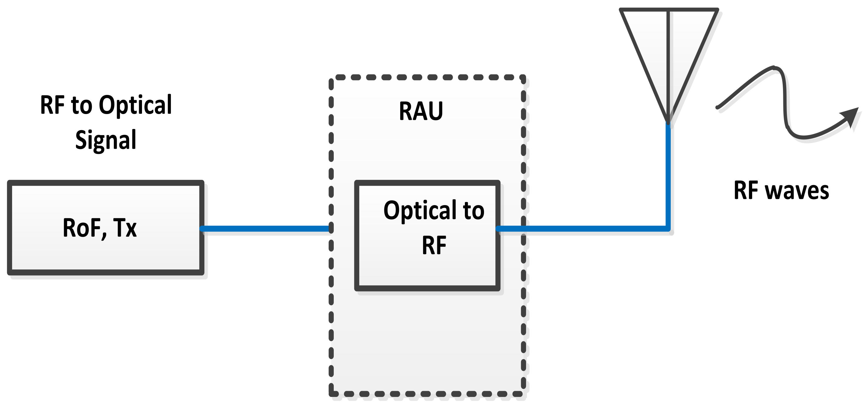
2. Proposed Radio over Fiber Network

The detailed structure of the proposed full-duplex RoF model, aiming to suppress the factors of NLIs and PAPRIs, is presented in Figure 1. WDM multiplexing and de-multiplexing techniques are applied, linking N channels within the central station (CS) and base station (BS) for upstream and downstream signals. At input side, the CS block covers continuous wave (CW) laser with 193.1 THz launching frequency and 5 MHz linewidth, launch power under −20 to 0 dBm range, pseudo-random bit sequence (PRBS) generator to induce 100 Gbps for initiating Gaussian pulse generator, and radio frequency (RF) based amplitude modulator, converting baseband signals into RF clock utilizing amplitude shift keying (ASK) [22]. Similarly, essential parameters like hybrid coupler (HC) operating at 90° is also installed inside CS. Which function is to attain the integrated RF and subcarrier multiplexed signals. Moreover, the process of getting information in the optical domain is performed in the CS section with the help of a dual drive and dual-port liNb much Zehnder modulator (MZM). It takes two forms of signals from 90° HC and optical waves from CW laser. The CS outflow is connected to WDM multiplexer reflective wavelength block-1 for transmitting and receiving the upstream and downstream signals. WDM multiplexer transmitter optical signals over single-mode fiber (SMF), purposing to cover long-range. In order to minimize the impact of NLIs and PAPRIs and balance the phase of propagating signals, SMF is followed by DCF and erbium-doped fiber amplifier (EDFA). Correspondingly, the BS block comprises WDM de-multiplexer, PIN photodetector, bandpass filter (BPL), RF de-modulator, BER analyzer and reflected wavelength block-2. The block of reflected wavelength reuses the downstream wavelength without the extra component of the CW laser. The performance of the received upstream signal through SMF is evaluated by a BER analyzer. The list of used parameters for investigating outcomes of the proposed full-duplex RoF model is depicted in Table 1.

3. Mathematical Calculations for Optical and Electronic Domains Based Parameters in Radio over Fiber Network

The fiber cable provides medium to deliver the wireless signals in their own RF waves as declared in Figure 2. It can be seen that the RoF system directly convert the optical signals into RF at high frequency. The optical signal of RF waves at the transmitter can be estimated [23,24,25] as
E ( t ) = A + c o s [ w 0 + 3 w LO ( t + d τ ) + θ ]
where A is the amplitude of the signal, w 0 denotes angular frequency of the optical signal, w LO describes the angular frequency of local oscillator (LO), d τ is the time delay and θ is the phase of the optical signal.
The induced multilevel pulses are estimated as [26,27,28] as
N o u t ( t ) = a , 0 t < t 1 b N i n ( t ) + a , t 1 t < t 1 + t c a , t 1 + t c t < T
where the incoming signals are denoted by N i n , linear gain is presented by b, a is applied for bias parameters, bit period is defined by T, t c is the duty cycle and pulse position is denoted by t 1 . The waves explain in Equation (4) are interfered by HC with 50 MHz frequency [29], which output is given as
N o u t ( t ) = D [ I ( t ) c o s ( 2 π f c t + ω c ) Q ( t ) s i n ( 2 π f c t + ω c ) ] + a
Here electrical input signals are shown by I and Q, D means gain of element, f c is the carrier frequency and ω c is phase of the signal. To estimate the PAPRTs, considering liNb MZM transmission with n sub-carriers with frequencies ( f i , i = 1 , 2 , . . . , n ). The continuous time signal S ( t ) based on modulation interval T and n T duration of inter symbol interference (ISI) [30,31,32] is defined as
S ( t ) = 0 t < n T m a x | ζ ( t ) | 2 E | ζ ( t ) | 2
The parameter E [ ζ ( t ) ] explains the expectation. The gain of electrical amplifier which suppress the high PAPRIs [33,34,35,36] is measured as
P o u t P i n = 10 b / 10
The outcomes of Equation (7) are measured in d B , which gives the amplifies electrical signals and is presented as
E o u t = E i n b
At the presence of PAPRIs and NLIs the power spectral density (PSD) function is induced and calculated as
P S D = P n o i s e . f s
Here P n o i s e means the noise power and f s denotes the frequency grid spacing which is defined as
f s = R s ψ s
In order to transmit the RF signals over optical CN the laser source is needed. So, in this model CW optical laser source is used. The electric field intensity of CW laser is define as
E 1 = E 0 e j 2 π f c t
From Equation (1) to Equation (10) the cosine of RF signal S ( t ) is calculated as
S ( t ) = V R F c o s ( 2 π f )
where V R F shows the driving voltage of RF. The optical field at output of intensity modulatot (IM) is given as
E 1 = E 0 2 [ e j π ( V D C + S ( t ) V π ) + e j π ( V D C + S ( t ) V π ) ]
where V D C is the DC bias voltage and V π explains the IM half wave voltage. Assuming ξ = π V R F / V π and ϖ = π V D C / V π , which explain the modulation index and initial phase caused by V D C of the IM respectively. From Equation (13) the E 1 can be extended as
E 1 ( t ) = E 0 e x p ( j 2 π f c t ) . c o s ϖ [ J 0 ( ξ ) + 2 Σ i = 1 ( 1 ) i J 2 i ( ξ ) c o s ( 4 i π f s t ) ] + s i n ϖ [ 2 Σ i = 1 ( 1 ) i J 2 i 1 ( ξ ) c o s ( 2 i 1 ) 2 π f s t ]
Here J i means the ith order of Bessel function. The transfer function of the transmitted signal is measured as
H ( f ) = α ( | f | < f 1 ) β ( f 1 | f | < f 2 ) 0 f 2 < | f |
where β is written as
β = 0.5 α 2 . 1 + c o s ( ( | f | f 1 / r p . δ ) . π )
Here α denotes insertion loss, r p means roll of factor and f 1 , f 2 are calculated as
f 1 = 1 r P f c ( 0 r p 1 )
f 2 = 1 + r P f c ( 0 r p 1 )
To describe, measuring the NLIs in the propagation of light wave in fiber are given below:
i A / z β 2 ( 2 A ) / ( t 2 ) i β 3 3 A ) / ( t 3 ) + γ | A | 2 A = i α / 2 A .
where complex term of electromagnetic field is defined by A, z is the fiber distance, t is the time, β 2 and β 3 are the group velocity dispersion (GVD) and nonlinear dispersion, respectively. The term γ is used for nonlinear coefficient and α means attenuation of the fiber. The nonlinear coefficient is further calculated as in terms of nonlinear refractive index n 2 and carrier wavelength λ 0 .
γ = ( 2 π n 2 ) / λ 0 .
The estimation of power consumption is written as,
P T = Ω D 1 C ( P C W + P m a p + P H C + P I S I + P r e f l e c t i v e b l o c k 1 + n M Z M . P M Z M )
where Ω denotes power conversion efficiency, P m a p is the signal mapping of power consumption, P H C means power consumption due to HC, P I S I explains ISI power consumption, P r e f l e c t i v e b l o c k 1 denotes power consumption reflective block-1 and n M Z M means the quantity of MZMs required for WDM-RoF transmission. Similarly, the power consumption at the Rx side is measured as
P R = Ω D 1 C ( P W D M d e M U X + P P D + P r e m o d u l a t i o n + P I S I + P a m p + P r e f l e c t i v e b l o c k 2 )
The parameters P W D M d e M U X , P P D , P r e m o d u l a t i o n i , P I S I , P r e f l e c t i v e b l o c k 2 and P a m p define the power consumption because of WDM de-MUX, PD, re-modulation, ISI transmission, amplification and reflective block-2, respectively. The BER is used for the analysis of NLIs and PAPRIs parameters, means that if these issues exist then how many bit can be transferred including low error size per bit. BER is given as
BER = 1 2 e r f OSNR 2
The e r f denotes error function the optical signal to noise ratio (OSNR) is described as
O S N R = E S N R φ 2 B r . m s y s
where B r defines the reference bandwidth, E S N R is the electrical SNR, φ is the total transmission symbol rate measured in Gbps and the last term of Equation (22) m s y s describes is the system margin.

4. Experimental Analysis and Discussion

This proposed model is analyzed analytically in Section 3, which describes that NLIs and PAPRIs create discontinuity in the transmission signals. Furthermore, current CNs face high capacity demands, the number of channels, data rates, and long transmission path. The full-duplex RoF-based CN is analyzed in this model to minimize the order of NLIs and PAPRIs. The simulation results are investigated in this section based on block description and analytical models.
The performance analysis of received power and BER, 1 to 10 km of transmission length, and 4 to 6 GHz RF range are presented in Figure 3. At −35 dBm received power, the outcomes are achieved above the threshold range. The order of NLIs and PAPRIs are enhanced with transmission range and the frequency of RF waves. Below 10 4 and 10 5 BERs are achieved at −20 dBm received Power 10 km length for 6 GHz and 4 GHz RF waves, respectively. Thus, there is a 0.1 BER difference between 6 and 4 GHz RF transmission. The phase errors (PEs) are induced in the transmission pulses by reason of NLIs and PAPRIs, which impact is declared in for different 0, 2.5, 5, and 8 deg PEs in terms of normalized signal to noise ratio and BER, with increasing PEs, the WDM-RoF presents the worst results. The simulation results in Figure 4 are investigated for RF 4 GHz, and length 5 km, the maximum 8 deg PE attains the threshold early than 0, 2, and 2.5 deg PEs. The analysis of the normalized signal to noise ratio as a function of BER at 5 km and 6 GHz RF waves is shown in Figure 5. This describes that with increasing the frequency of RF waves, the outcomes become worse as compared to Figure 4 which presents the outcomes of the presented model at 5 km and 4 GHz RF range. Similarly, Figure 6 and Figure 7 contain the results of the presented model of 4 GHz and 6 GHz RF range at 10 km transmission length. It is depicted from the results that the PEs factors disturb system fidelity. It is recorded that till six normalized signals to noise ratio, the outcomes of the full-duplex system are above the threshold BER. With increasing the PE till 8 deg, then the proposed model presents bad outcomes as shown in Figure 6 and Figure 7. Greater than seven normalized signals to noise ratio, the factors of NLIs, and PAPRIs are compensated successfully as declared in Figure 6 and Figure 7. The main mechanisms to evaluate the PAPRIs and NLIs are full-duplex RoF linked with WDM and the DCF with −20, −30, −35, and −40 ps/nm/km dispersion magnitudes. These mentioned DCF dispersion are studied and analyzed using 4 and 6 GHz RF waves and 5 to 10 km transmission range. Figure 8 explains the information among the transmission range and BER, for −20, −30, −35, and −40 ps/nm/km DCF dispersion values, operating at 4 GHz RF range, which clarify that the above 8 km of fiber length the influences of NLIs and PAPRIs produce BER in the limited range. Moreover, the achievements of the full-duplex WDM based RoF model at −40 ps/nm/km DCF dispersion are efficient compared to −35, −30, and 20 ps/nm/km dispersion of DCF. Keeping DCF dispersion at −40 ps/nm/km for 5 km fiber length and RF 4 GHz, 2.2× 10 7 BER is attained. On the other hand, the outcomes touch the threshold range by employing DCF with −35, −30, and −20 dispersion with the above-covered path and RF values. Figure 9 defines the same results as discussed in Figure 8 with transmission range and BER parameters, however here, the capacity of RF signals increased to 6 GHz. This concludes that the capacity of transmitted data has valuable contributions towards NLIs and PAPRIs. Figure 10 depicts the behavior of NLIs and PAPRIs and the proposed full-duplex RoF model and the outcomes while compensating these factors. The simulation results on account of launch power and BER are shown in Figure 10 RoF model, which covers 5 km transmission length and 4 GHz RF capacity. The destructive analysis is presented when NLIs and PAPRIs are not balanced. The results in Figure 10 are compared among with addressed NLIs and PAPRIs and without addressed NLIs and PAPRIs. Moreover, the results include the individual performance of each addressed NLIs and PAPRIs and without addressed NLIs and PAPRIs, which denotes that in every case, the outcomes without addressing NLIs or PAPRIs are weak and interrupt CN efficiency. The order of NLIs and PAPRIs are increased directly with RF and transmitted length as presented in Figure 11, Figure 12 and Figure 13. Figure 11 explores the relation among input power and BER for 5 km 6 GHz, Figure 12 presents the outcomes of the presented model based on input power and BER for 10 km 4 GHz and Figure 13 defines the results at 10 km and 6 GHz RF waves, using input power vs BER. In Figure 11 at 0 dBm input power for 5 km length and 4 GHZ RF, 10 7 BER is attained, with applying management techniques, minimizing NLIs and PAPRIs. However, about 0.001 less BER is gained using a conventional system if no mechanism is installed for treating the effects of NLIs and PAPRIs. Similarly, 10 6 is calculated of the proposed full-duplex RoF model, working at 10 km and 4 GHz RF parameters. Furthermore, Figure 13 estimates 10 5 and 3.1× 10 3 BER at 0 dBm, comparing compensation of NLIs and PAPRIs. From Figure 10, Figure 11, Figure 12 and Figure 13 it is evaluated that outcomes of the full-duplex RoF model are destroyed badly if there are no procedures applied for deducing the NLI and PAPRIs. In addition, it is showed the negative impacts of NLIs are higher than PAPRIs. Figure 14 evaluates the received power vs input power at −10 to 0 dBm for 1, 5, and 10 km fiber length and 6 GHz RF waves. It is depicted from Figure 14 that for higher length because of NLIs, PAPRIs and PEs, the maximum penalty is recorded in received power. The presented model is also investigated, employing BER analyzer, optical spectrum analyzer and RF spectrum analyzer, which are explained in Figure 15a–d, Figure 16a–d and Figure 17a–d. Figure 15a shows the performance of the full-duplex RoF model at 10 km of transmission range and 6 GHz of RF waves. When there is no technique addressed for controlling NLIs and PAPRIs. Figure 15b presents the model without NLIs and PAPRIs compensated at 10 km and 4 GHz RF waves. The compensated NLIs, PAPRIs results of the full-duplex RoF model where NLIs and PAPRIs are reduced depict in Figure 15c,d for 10 km, 4 GHz, and 10 km 6 GHz, respectively. Figure 16a shows the input transmitted signals, Figure 16b,c clarify without NLIs and PAPRIs managed signals at 5 km and 10 km of path cover with RF 4 GHz, respectively. The NLIs and PAPRIs compensated output signals at path cover of 10 km are presented in Figure 16d. Figure 17a contains the results of input signals. Figure 17b consists of interrupted signals due to NLIs and PAPRIs of the proposed full-duplex RoF model at Length = 5 km and RF = 4 GHz. The worst performance at 10 km length and RF 4 GHz of the model without compensated NLIs and PAPRIs is explained in Figure 17c. While outcomes of the applied technique to suppress NLIs, and PAPRIs at 10 km and RF 4 GHz are described in Figure 17d.
The proposed outcomes, which are explained in Figure 3, Figure 4, Figure 5, Figure 6, Figure 7, Figure 8, Figure 9, Figure 10, Figure 11, Figure 12, Figure 13, Figure 14, Figure 15, Figure 16 and Figure 17d depict that the performance of the treated NLIs and PAPRIs model is efficient many times as compared to without approached NLIs and PAPRIs. The presented RoF model outcomes are correlated with existed models as shown in Table 2, which specifies the fruitful outcomes of the proposed framework.

5. Conclusions

The full duplex RoF model is considered a fruitful solution in current era to support maximum number of users including video based services. Therefore, in this paper a full duplex WDM based RoF model is projected in terms of hybrid coupling mechanism. The prominent factors like NLIs and PAPRIs are studied and minimized in this presented model. The background of the proposed model is analyzed with RF and optical domain infrastructure. Mathematical model is investigated to explore the originality of transmitted signals, the discontinuity of pulses due to optical domain and electrical domain related issues like NLIs, and PAPRIs, using the proposed analytical model. The presented results are investigated in terms of 1 km to 10 km of transmission range 4 and 6 GHz of RF magnitudes, input power between -20 to 0 dBm, received power with −40 to −18 dBm values and 0 to 8 normalized to signal noise ratio. It is concluded that there is a clear difference among with suppressed NLIs, and PAPRIs and without managed NLIs and PAPRIs.

Author Contributions

Data curation—H.Y.; Formal analysis—S.T., A.A., F.M. and F.A. (Fayadh Alenezi); Funding acquisition—H.Y., S.T. and N.A.; Investigation—F.A. (Farman Ali), S.T., A.A., F.M., F.A. (Fayadh Alenezi) and K.H.; Methodology–A.A. and F.M.; Project administration—F.A. (Farman Ali); Resources—F.A. (Fayadh Alenezi) and K.H.; Software–F.A. (Fayadh Alenezi) and K.H.; Supervision—A.A.; Visualization—F.M., F.A. (Fayadh Alenezi) and N.A.; Writing—original draft, H.Y. and F.A. (Farman Ali); Writing—review & editing, S.T., H.K., A.A. and F.M. All authors have read and agreed to the published version of the manuscript.

Funding

This work is supported in part by the Beijing Natural Science Foundation (No. 4212015), Natural Science Foundation of China (No. 61801008), China Ministry of Education-China Mobile Scientific Research Foundation (No. MCM20200102), China Postdoctoral Science Foundation (No. 2020M670074), Beijing Municipal Commission of Education Foundation (No. KM201910005025), China National Key Research and Development Program (No. 2018YFB0803600).

Institutional Review Board Statement

Not applicable.

Informed Consent Statement

Not applicable.

Data Availability Statement

Data will be available as per request.

Acknowledgments

This work is supported in part by the Beijing Natural Science Foundation (No. 4212015), Natural Science Foundation of China (No. 61801008), China Ministry of Education-China Mobile Scientific Research Foundation (No. MCM20200102), China Postdoctoral Science Foundation (No. 2020M670074), Beijing Municipal Commission of Education Foundation (No. KM201910005025), China National Key Research and Development Program (No. 2018YFB0803600).
Princess Nourah bint Abdulrahman University Researchers Supporting Project number (PNURSP2022R192), Princess Nourah bint Abdulrahman University, Riyadh, Saudi Arabia.

Conflicts of Interest

The authors declare no conflict of interest.

References

  1. Khan, Y.; Ali, F.; Ali, A. Impact of nonlinear impairments on power budget and transmission power penalties in high capacity long haul optical networks. Wirel. Pers. Commun. 2019, 106, 1001–1013. [Google Scholar] [CrossRef]
  2. Sharma, S.R.; Rana, S. Comprehensive Study of Radio over Fiber with different modulation techniques—A review. Int. J. Comput. Appl. 2017, 170, 22–25. [Google Scholar] [CrossRef]
  3. Anjum, O.F.; Horak, P.; Jung, Y.; Suzuki, M.; Yamamoto, Y.; Hasegawa, T.; Petropoulos, P.; Richardson, D.J.; Parmigianil, F. Bandwidth enhancement of inter-modal four wave mixing Bragg scattering by means of dispersion engineering. APL Photonics 2018, 4, 368–370. [Google Scholar] [CrossRef] [Green Version]
  4. Irfan, M.; Ali, F.; Muhammad, F.; Habib, U.; Alwadie, A.S.; Glowacz, A.; Abbas, Z.H. DSP-Assisted nonlinear impairments tolerant 100 Gbps optical backhaul network for long-haul transmission. Entropy 2020, 22, 1062. [Google Scholar] [CrossRef]
  5. El-Nahal, F.I.A. WDM-PON with DPSK modulated downstream and OOK modulated upstream signals based on symmetric 10 Gbit/s wavelength reused bidirectional reflective SOA. Optoelectron. Lett. 2017, 13, 67–69. [Google Scholar] [CrossRef]
  6. Ali, F.; Khan, Y.; Qureshi, S.S. Transmission performance comparison of 16*100 Gbps dense wavelength division multiplexed long haul optical networks at different advance modulation formats under the influence of nonlinear impairments. J. Opt. Commun. 2018. [Google Scholar] [CrossRef]
  7. Cartledge, J.C.; Guiomar, F.P.; Kschischang, F.R.; Liga, G.; Yankov, M.P. Digital signal processing for fiber nonlinearities. Opt. Express 2017, 25, 1916–1936. [Google Scholar] [CrossRef] [PubMed] [Green Version]
  8. Bakhshali, A.; Chan, W.Y.; Cartledge, J.C.; OSullivan, M.; Laperle, C.; Borowiec, A.; Roberts, K. Frequency-domain Volterra-based equalization structures for efficient mitigation of intrachannel Kerr nonlinearities. J. Light. Technol. 2016, 34, 1770–1777. [Google Scholar] [CrossRef]
  9. Liu, X.; Chraplyvy, A.; Winzer, P.; Tkach, R.; Chandrasekhar, S. Phase-conjugated twin waves for communication beyond the Kerr nonlinearity limit. Nat. Photonics 2013, 7, 560. [Google Scholar] [CrossRef]
  10. Ali, F.; Muhammad, F.; Habib, U.; Khan, Y.; Usman, M. Modeling and minimization of FWM effects in DWDM-based long-haul optical communication systems. Photon Netw. Commun. 2021, 41, 36–46. [Google Scholar] [CrossRef]
  11. Habib, U.; Aighobahi, A.E.; Wang, C.; Gomes, N.J. Radio over fiber transport of mm-Wave 2 × 2 MIMO for spatial diversity and multiplexing. In Proceedings of the IEEE International Topical Meeting on Microwave Photonics (MWP), Long Beach, CA, USA, 31 October–3 November 2016; pp. 39–42. [Google Scholar]
  12. Wang, B.; Peng, L.; Ho, P. Energy-efficient radio-over-fiber system for next-generation cloud radio access networks. J. Wirel. Com. Netw. 2019, 2019, 118. [Google Scholar] [CrossRef]
  13. Ali, A.H.; Farhood, A.D. Design and performance analysis of the WDM Schemes for radio over fiber system With different fiber propagation losses. Fibers 2019, 7, 19. [Google Scholar] [CrossRef] [Green Version]
  14. Li, G.; Lin, Z.; Huang, X.; Li, J. A radio over fiber system with simultaneous wireless multi-mode operation based on a multi-wavelength optical comb and pulse-shaped 4QAM-OFDM. Electronics 2019, 8, 1064. [Google Scholar] [CrossRef] [Green Version]
  15. Li, J.L.; Zhao, F.; Yu, J. D-band millimeter wave generation and transmission though radio-over-fiber system. IEEE Photonics J. 2019, 12, 5500708. [Google Scholar] [CrossRef]
  16. Li, W.; Chen, A.; Li, T.; Penty, R.V.; White, I.H.; Wang, X. Novel digital radio over fiber (DRoF) system with data compression for neutral-host fronthaul applications. IEEE Access 2020, 8, 40680–40691. [Google Scholar] [CrossRef]
  17. Sharma, V.; Sergeyev, S.; Kaur, J. Adaptive 2×2 MIMO employed wavelet-OFDM-radio over fibre tTransmission. IEEE Access 2020, 8, 23336–23345. [Google Scholar] [CrossRef]
  18. Kim, J.; Lee, H.; Park, S.; Lee, I. Minimum rate maximization for wireless powered cloud radio access networks. IEEE Trans. Veh. Technol. 2019, 68, 1045–1049. [Google Scholar] [CrossRef]
  19. Muramoto, K.; Inoue, A.; Koike, Y. Noise and distortion reduction in OFDM radio-over-fiber link by graded-index plastic optical fiber. IEEE Photonics Technol. Lett. 2020, 32, 835–838. [Google Scholar] [CrossRef]
  20. Qamar, F.; Islam, M.K.; Ali, S.Z.; Ali, M. Secure duobinary signal transmission in optical communication networks for high performance & reliability. IEEE Access 2018, 5, 17795–17802. [Google Scholar]
  21. Zhang, H.; Batshon, H.G.; Davidson, C.R.; Foursa, D.G.; Pilipetskii, A. Multi dimensional coded modulation in long-haul fiber optic transmission. J. Light. Technol. 2015, 33, 2876–2883. [Google Scholar] [CrossRef]
  22. Stojanovic, N.; Changsong, X. An efficient method for skew estimation and compensation in coherent receivers. IEEE Photonics Technol. Lett. 2016, 28, 489–492. [Google Scholar] [CrossRef]
  23. Tanimura, T.; Hoshida, T.; Kato, T.; Watanabe, S. OSNR estimation providing self-confidence level as auxiliary output from neural networks. J. Lightw. Technol. 2019, 37, 1717–1723. [Google Scholar] [CrossRef]
  24. Zhuge, Q.; Chen, X. Advances in modulation and DSP for optical transmission systems. J. Opt. Commun. 2018, 409, 1–136. [Google Scholar] [CrossRef]
  25. Ali, F.; Ahmad, S.; Muhammad, F.; Abbas, Z.H.; Habib, U.; Kim, S. Adaptive equalization for dispersion mitigation in multi-channel optical communication networks. Electronics 2019, 8, 1364. [Google Scholar] [CrossRef] [Green Version]
  26. Maharana, D.; Rout, R. A 4 channel WDM based hybrid optical Fiber/FSO communication system using DP QPSK modulation for bit rate of 100/112 Gb/s. Int. J. Eng. Res. Technol. 2019, 8, 442–445. [Google Scholar]
  27. Obaid, H.M.; Shahid, H. Achieving high gain using Er-Yb codoped waveguide/fiber optical parametric hybrid amplifier for dense wavelength division multiplexed system. Opt. Eng. 2018, 57, 056108. [Google Scholar] [CrossRef]
  28. Argyris, N.; Giannoulis, G.; Kanta, K.; Iliadis, N.; Vagionas, C.; Papaioannou, S.; Kalfas, G.; Apostolopoulos, D.; Caillaud, C.; Debrégeas, H.; et al. A 5G mmWave fiber-wireless IFoF analog mobile fronthaul link with up to 24 Gb/s multi-band wireless capacity. J. Lightw. Technol. 2019, 37, 2883–2891. [Google Scholar] [CrossRef]
  29. Ali, F.; Khan, Y.; Muhammad, F.; Habib, U.; Abbas, Z.H.; Khan, M.A.; Ali, A. Extenuation of phase shift influenced nonlinear impairments in fiber optics network. Trans. Emerg. Telecommun. Technol. 2020, 31, e3930. [Google Scholar] [CrossRef]
  30. Tipsuwannakul, E.; Li, J.; Karlsson, M.; Andrekson, P.A. Performance comparisons of DP16-QAM and duobinary-shaped DP-QPSK for optical systems with 4.1 Bit/s/Hz spectral efficiency. J. Light. Technol. 2012, 30, 2307–2314. [Google Scholar] [CrossRef]
  31. Noor, S.; Assimakopoulos, P.; Gomes, N.J. A flexible subcarrier multiplexing system with analog transport and digital processing for 5G (and beyond) fronthaul. J. Lightw. Technol. 2019, 37, 3689–3700. [Google Scholar] [CrossRef]
  32. Yu, W.; Zeng, B.; Peng Yan, S.; Huang, Y.; Jiang, H. Multi-objective optimum design of high-speed backplane connector using particle swarm optimization. IEEE Access 2018, 6, 35182–35193. [Google Scholar] [CrossRef]
  33. Perin, J.K.; Shastri, A.; Kahn, J. Design of low-power DSP-free coherent receivers for data center links. J. Light. Technol. 2017, 35, 4650–4662. [Google Scholar] [CrossRef]
  34. Miao, X.; Bi, M.; Fu, Y.; Li, L.; Hu, W. Experimental study of NRZ, Duobinary, and PAM-4 in O-band DML-based 100G-EPON. IEEE Photonics Technol. Lett. 2017, 29, 1490–1493. [Google Scholar] [CrossRef]
  35. Dong, Y.; Al-Rawachy, E.; Giddings, R.P.; Jin, W.; Nesset, D.; Tang, J.M. Multiple channel interference cancellation of digital filter multiple access PONs. J. Light. Technol. 2017, 35, 34–44. [Google Scholar] [CrossRef]
  36. Muhammad, F.; Ali, F.; Habib, U.; Usman, M.; Khan, I.; Kim, S. Time domain equalization and digital back-propagation method-based receiver for fiber optic communication systems. Int. J. Opt. 2020, 2020, 3146374. [Google Scholar] [CrossRef]
  37. Dat, P.T.; Kanno, A.; Inagaki, K.; Kawanishi, T. High-Capacity Wireless Backhaul Network Using Seamless Convergence of Radio-over-Fiber and 90-GHz Millimeter-Wave. J. Light. Technol. 2014, 32, 3910–3923. [Google Scholar] [CrossRef]
  38. Vázquez, C.; López-Cardona, J.D.; Lallana, P.C.; Montero, D.S.; Al-Zubaidi, F.M.A.; Pérez-Prieto, S.; Garcilópez, I.P. Multicore Fiber Scenarios Supporting Power Over Fiber in Radio Over Fiber Systems. IEEE Access 2019, 7, 158409–158418. [Google Scholar] [CrossRef]
Figure 1. WDM based full duplex RoF system including CS and BS.
Applsci 12 00753 g001
Figure 2. RF and optical waves convergence scheme.
Applsci 12 00753 g002
Figure 3. Received power against BER at 2, 5, 10 km fiber range, 4 and 6 GHz radio frequency, and 100 Gbps data rate.
Applsci 12 00753 g003
Figure 4. BER in terms of normalized signal to power ratio for fiber length of 5 km, 4 GHz RF range and PEs with 0, 2.5, 5 and 8 deg.
Applsci 12 00753 g004
Figure 5. Normalized signal to noise ratio vs BER at 0, 2.5, 5 and 8 deg of PEs, 6 GHz RF range, fiber length with magnitude of 10 km and 100 Gbps data rate.
Applsci 12 00753 g005
Figure 6. Results among BER and normalized signal to noise ratio with length = 10 km, RF = 4 GHz, data rate = 100 Gbps and PEs =0, 2.5, 5 and 8 deg.
Applsci 12 00753 g006
Figure 7. Simulation analysis for 10 km of optical fiber, 100 Gbps data rate, PEs with 0, 2.5, 5 and 8 deg and 6 GHz RF magnitude based on normalized signal to noise ratio and BER.
Applsci 12 00753 g007
Figure 8. Estimation of −20, −30, −35 and −40 ps/nm/km DCF with transmission range as a function of BER at RF = 4 GHz, data rate = 100 Gbps and 16 channels (Updated).
Applsci 12 00753 g008
Figure 9. BER against transmission path cover at 6 GHz of RF waves, DCF = −20, −30, −35 and 40 here. ps/nm/km, data rate = 100 Gbps and channels = 16.
Applsci 12 00753 g009
Figure 10. Input power in terms of BER at length 5 km and 4 GHz RF range for evaluating with and without addressed NLIs and PAPRIs.
Applsci 12 00753 g010
Figure 11. BER as a function of launch power with 5 km fiber length and 6 GHz frequency range.
Applsci 12 00753 g011
Figure 12. Launch power against BER for length of 10 km, RF = 4 GHz at with and without addressed NLIs and PAPRIs.
Applsci 12 00753 g012
Figure 13. Input power against BER for 6 GHz RF values, length = 10 km, data rate = 100 Gbps and channels = 16 to analyze NLIs and PAPRIs.
Applsci 12 00753 g013
Figure 14. Output power vs input power for 1, 5 and 10 Km and RF = 6 GHz.
Applsci 12 00753 g014
Figure 15. BER eye-diagrams; (a) BER at 10 km distance and 6 GHz RF without addressed NLIs, and PAPRIs, (b) BER at length = 10 km RF = 4 GHz without addressed NLIs and PAPRIs, (c) BER at 10 km distance and 6 GHz RF with addressed NLIs and PAPRIs, and (d) BER at L = 10 km distance and RF = 4 GHz with addressed NLIs and PAPRIs.
Applsci 12 00753 g015
Figure 16. Optical spectrum analyzer; (a): Input transmitted signals, (b): Without addressed of NLIs and PAPRIs at 5 km of length, (c): Without addressed of NLIs and PAPRIs at 10 km of length, (d): Output signals with managed of NLIs and PAPRIS at 10 km of length.
Applsci 12 00753 g016
Figure 17. RF spectrum analyzer; (a): Input signals, (b): NLIs and PAPRIs interrupted signals, (c): Interrupted signals due to NLIs, and PAPRIs at length = 5 km and RF = 4 GHz, (d): Output signals with addressed NLIs, and PAPRIs with length = 5 km and RF = 4 GHz.
Applsci 12 00753 g017
Table 1. List of elements applied for measuring the proposed model outcomes.
DescriptionMagnitude
Effective area80 μ m 2
Launch power−19 to 1 dBm
Transmission range1 to 10 km
Received power−40 dBm to −20 dBm
Spacing among channels25 to 50 GHz
Reference wavelength1553 nm
Channel Quantity4–16
Nonlinear dispersion−2.5 ps 3 /km
RF range4 to 6 GHz
Line width5 MHz
Extension ratio10 dB
Table 2. Correlation of proposed framework with existed models.
Parameter Description[37][38]Presented RoF Model
Modulation schemeOFDM64-QAMDual drive and dual port liNb MZM
Received power (dBm)−35 to −25 dBm−40 to −22 dBm−36 to −18 dBm
Input Power (dBm)−22 to −3 dBm−23 to −2 dBm−20 to −0 dBm
Length6 km8 km10 km
BER 1.4× 10 3 2 × 10 5 4.1× 10 7
Publisher’s Note: MDPI stays neutral with regard to jurisdictional claims in published maps and institutional affiliations.

