
Vibration Properties of Dual-Rotor Systems under Base Excitation, Mass Unbalance and Gravity


1
School of Energy and Power Engineering, Beihang University, Beijing 100083, China
2
Beijing Key Laboratory of Aero-Engine Structure and Strength, Beijing 100191, China
3
Beijing Key Laboratory of Long-life Technology of Precise Rotation and Transmission Mechanisms, Beijing Institute of Control Engineering, No. 104 Youyi Road, Haidian District, Beijing 100094, China
*
Author to whom correspondence should be addressed.
Appl. Sci. 2022, 12(3), 960; https://0-doi-org.brum.beds.ac.uk/10.3390/app12030960
Submission received: 1 January 2022
/
Revised: 13 January 2022
/
Accepted: 14 January 2022
/
Published: 18 January 2022
(This article belongs to the Special Issue Vibration Control and Applications)
Abstract
:Rotor systems installed in a transportation system or under seismic excitations are considered to have a moving base. Although extensive research has been conducted on the dynamic behavior of the single-rotor system under base motions, few studies have dealt with the dynamics of dual-rotor systems, especially the counter-rotating dual-rotor systems used in airplane engines. Moreover, mass unbalance and gravity are unavoidable excitations for most rotor systems. Therefore, the vibration properties of a counter-rotating dual-rotor system with the coupled effects of base motions, mass unbalance and gravity are investigated in this paper for the first time. Using the Lagrange principle associated with the finite element method, a general model for dual-rotor systems under base motions was established by using Timoshenko beam elements, leading to a detailed analysis of the natural properties and harmonic responses of the system. The results revealed that different whirling modes (backward, forward or both) may be mutually excited. This research can be helpful for the design and vibration analysis of dual-rotor systems concerned with base motion.
1. Introduction
Rotating machines such as pumps, generators and ground gas turbines are fundamental equipment in the modern engineering applications. Gravity and mass unbalance from center-of-mass eccentricity along the rotor axis are unavoidable excitation sources for analyzing these rotor system problems. Moreover, base excitations should also be concerned for a rotor system mounted on a transportation system or under seismic excitation. These three excitations have mutual influences that induce intricate resonance problems. It is even more complicated for a counter-rotating dual-rotor system with inter-shaft bearings in airplane engines, compared with a single rotor system. Thus, it is important to reveal the vibration properties in detail for the dual-rotor system under base motions, mass unbalance and gravity.
As mentioned in the authors’ former work [1], many researchers have contributed to our understanding of the dynamics of the rotor system under base motions. The accurate description of base motions and simulated deformation of the rotor are the two priorities for rotor system modeling. For the former task, two groups of Euler angles were used to describe the relative rotations among the rotor, base and ground, and coordinate transformation theory made the model adaptable to arbitrary base motion as shown by, for example, Das [2,3], Dakel [4,5] and Chen [1]. For the latter task, the application of the finite element method made the model more realistic [4,5] compared with the Jeffcott rotor [6,7,8,9,10,11], a rigid disk with only four degrees of freedom [12,13,14,15,16,17,18,19], and the rigid disk in the Rayleigh–Ritz method for the shaft [20,21,22,23]. Especially compared with the Euler–Bernoulli beam element [24,25,26,27,28,29], the Timoshenko beam element [4,5,12,13,30,31,32,33,34,35,36,37] took the shear deformation of the shaft into account. Therefore, it was used to improve the model established by the author in [1].
Various types of base motion have been widely investigated to find out their effects on the dynamic behavior of the rotor systems. Random and shock excitations to bases have been studied by scholars to help maintain the stable operation of rotating machines under seismic excitations [6,12,13,14,30]. Transient or aperiodic base motion is involved mainly due to aircraft flight maneuvers [7,8,9,10,11,16,17,18]. Research into this aspect of the rotor system focuses on the effects of additional centrifugal force and gyroscopic momentum from the base motion on the nonlinear responses, which often refer to nonlinear factors. The periodic base motions are attracting more and more attention from scholars in recent years. The singular or combined effects of constant base rotation, harmonic base translation and harmonic base rotation are discussed in detail in [4,5,20,21,22,23,24,25,26,27,28,29,30,31,32,33,34,35,36,37]. The specific stability problem induced by the nonlinearity from time-varying base rotations is a major topic of investigation [20,21,22,25,27,32,33]. In addition, some scholars [2,3,28,29] are devoted to minimizing the vibration induced by base motions by using an active control method or magnetic bearings. However, all the above studies are for single-rotor systems.
Extensive research has been conducted on the dynamic behavior of dual-rotor systems with a fixed base. Hibner [38] presented an efficient analytical technique to predict the vibratory response of an engine with nonlinear viscous damping. He pointed out that the aircraft engine structure must be analyzed in detail to provide all critical speeds and responses to imbalance. Glasgow et al. [39] performed a method of component mode synthesis for the analysis of multi-shaft rotor-bearing systems and maintained the essential dynamic characteristics of the lower modes after reducing the size of the overall problem. Li et al. [40] employed a component mode method to the dynamic analysis of large flexible rotor systems and a two-spool test rig was used to illustrate the capability and versatility of the component mode method. Gupta et al. [41] investigated the critical speeds, mode shape and unbalance responses both numerically and experimentally. The results are in reasonable agreement and show the appearance of a cross-excitation between the inner and outer shafts. Ferraris et al. [42] used a simple model of non-symmetric co-axial co-rotating or counter-rotating rotors to give analytical expression of the critical speeds, mass unbalance responses and sense of whirl. Chiang et al. [43] showed two methods to compute the critical speeds for a co-rotating dual-rotor system that has different advantages. In addition, the speed ratio and intershaft bearing stiffness were found out to be two important factors for the dynamic behavior of the system. Guskov et al. [44] examined the dynamics of a dual-rotor system both experimentally and numerically, and pointed out that taking into consideration the tilt stiffness in the system can improve the theoretical model. Zhang et al. [45] put forward a critical speed prediction method (similar to that of Chiang [43]) for a dual-rotor system based on the finite element method. Moreover, a vibration mode selection technique was presented to identify the backward and forward whirling modes.
Few studies have included base motions in the dynamic behavior analysis of a dual-rotor system. Chen et al. [46,47], though, did develop a dynamic model that included mass unbalance and base motions, using the Lagrange principle and finite element method. Steady-state characteristics during stable operation, and transient characteristics during the start-up of the co-rotating dual-rotor system were investigated adequately. Constant base rotation, harmonic translation and mass unbalance were the major forces involved in the investigation. However, the counter-rotating type for the dual-rotor system and excitations from gravity were not taken into account.
In a word, the synthesized influences of base motions, mass unbalance and gravity on the dynamic behavior of counter-rotating dual-rotor systems still lack in-depth investigation. Therefore, this article develops a general model for such a dynamic analysis under six degrees of base motions based on the Lagrange principle and finite element method and using Timoshenko beam elements to model the shaft. Constant base rotation, harmonic base translation, mass unbalance force and gravity were taken into account. The natural properties and harmonic responses of the counter-rotating dual-rotor system are analyzed in detail.
2. Modeling for a Dual-Rotor System under Base Motions
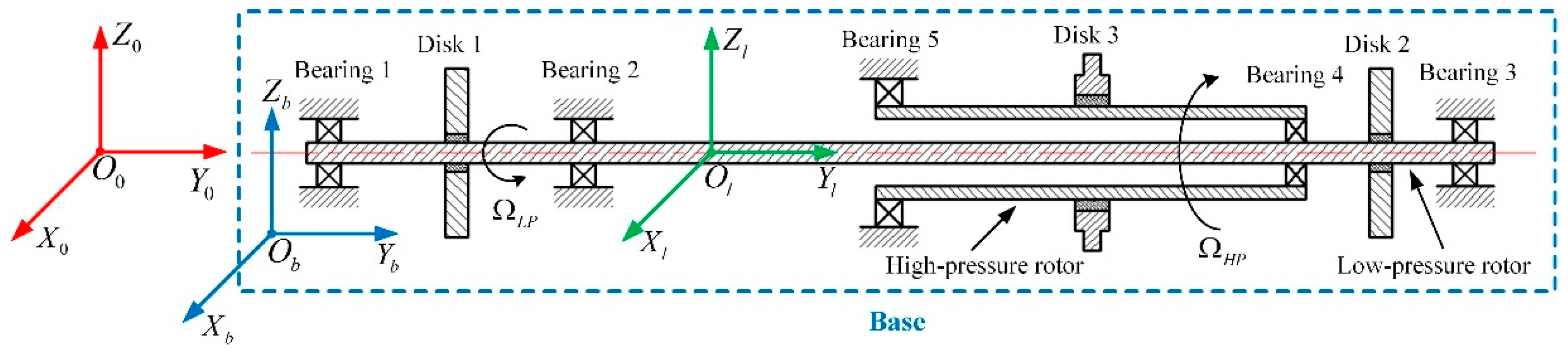
As shown in Figure 1, a counter-rotating dual-rotor system is mounted on a moving rigid base (the blue dashed box), which consists of a low-pressure rotor with a low rotating speed and a high-pressure rotor with a higher rotating speed . The excitations due to the base motions, mass unbalance and gravity are taken into consideration. Three coordinate systems are defined in this paper: an inertial frame of reference , which is fixed to the ground; a non-inertial frame of reference , which moves with the rigid base; and a local frame of reference , which moves with the rotor. All three coordinate systems have relative movement to each other. For the dual-rotor model in this paper, longitudinal vibration and rotor torsion are ignored.
2.1. Modeling for the Disks, Unbalance Force and Linear Bearings
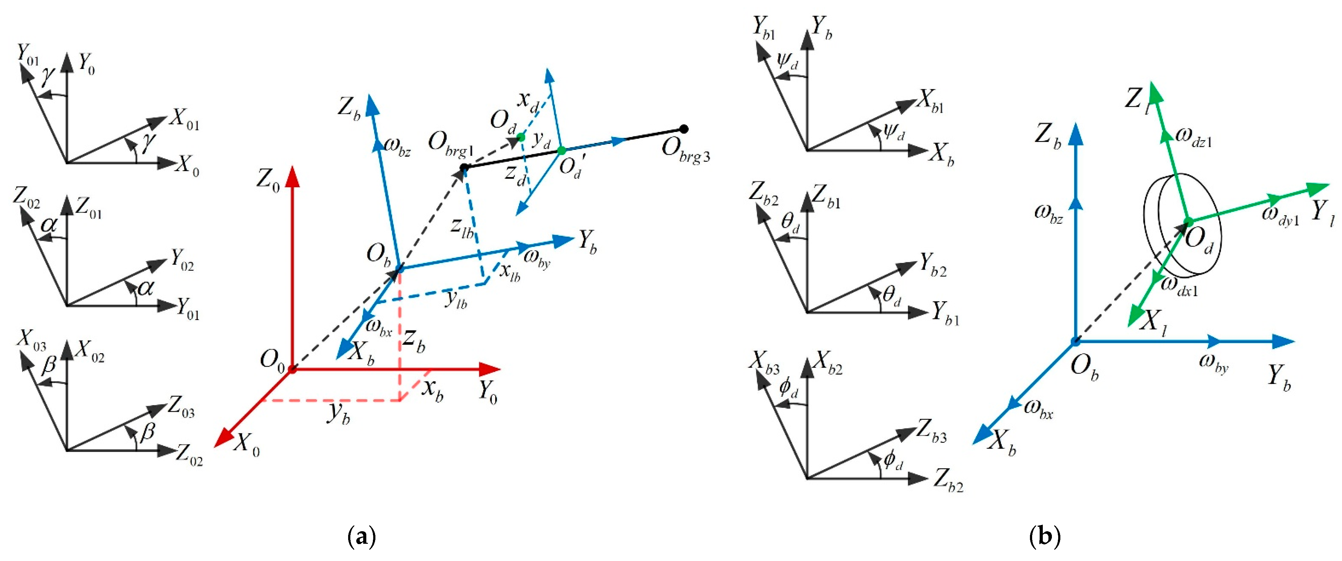
The modeling for the disks, unbalance force and linear bearings is similar to that in [1] and is quite simplified in this paper. Three base translations (, and ) and three base rotations (pitching angle , rolling angle and yawing angle ) are shown in Figure 2a. Two transverse displacements ( and ) and two angular displacements ( and ) relative to the base for the disk are unknown and remain to be solved as shown in Figure 2b. Firstly, the kinetic energy and the gravitational potential energy of the disk and the kinetic energy of the unbalanced mass are obtained as
where ; and are the mass and mass-moment matrix of inertia of the disk; and are the absolute translational velocity and absolute angular velocity of the disk, respectively; is the gravitational acceleration; is the absolute vertical displacement of the disk; denotes the unbalanced mass; is the absolute linear velocity of the unbalanced mass; and the superscript is the matrix transposition symbol.
Secondly, the Lagrange principle is applied to achieve the final equations of motion (EOMs) of the disk as following
where is the general displacement vector of the disk; and are the conventional mass and gyroscopic matrices of the disk, respectively; is or corresponding to the low-pressure or high-pressure rotor; is the additional damping matrix of the disk due to base rotations; , and are external forces induced by base linear motions, base angular motions and gravity, respectively; and is an additional external force due to both the base rotations and the position vector from the origin of the frame to the center of the left bearing.
The final unbalancing forces are given by
where denotes the eccentricity of the unbalanced mass, and is the unbalanced angle with respect to the axis .
The linear bearings are concerned by placing the stiffness and damping of the bearings in the proper position in the stiffness matrices and damping matrices.
2.2. EOMs for the Shaft
A two-node Timoshenko beam replaced the Euler beam element from [1] to model the shear deformation effect on the shaft. The two nodes of the shaft element were and , and their position vectors with respect to the base frame were defined as and . The length of the shaft element was denoted as . After the discretization of the shaft, the values of , and remained constant. The general coordinate vector of the shaft element was
After taking an arbitrary point with a distance of along from into consideration, its position vector was defined with respect to the base frame as , where ; and are unknowns; and and were attained by interposition:
For the Timoshenko beam element, the interposition function is given by
where
The absolute linear velocity and absolute angular velocity of the point can be derived in similar steps as the disk. Then, the kinetic energy of a shaft element is given by
where ; , , and are, respectively, the material density, area of shaft cross-section, the transverse and polar mass-moment of inertia per unit length of the shaft element. For a circular shaft, the and where ( is the shaft outer radius and is the shaft inner radius). The strain energy of a shaft element is given by
where is the Young’s modulus of the shaft material.
Let be the component of the absolute position vector along the axis . The gravitational potential energy of a shaft element is given by
After substituting , and into the Lagrange equation, simplifying (, , , ) and ignoring the high-order terms, the EOMs for a shaft element was accomplished as
where , and are the classical mass, gyroscopic and stiffness matrices of the Timoshenko beam element, respectively; and are additional time-varying damping and stiffness matrices due to the time-variable base rotations; , and are external forces motivated by base translations, base rotations and gravity, respectively; and are additional external forces due to both the position vector in Figure 2 and base rotations. The origin of the base frame is set right in the center of bearing 1; thus, . The precise coefficient matrices and force vectors are listed as follows:
2.3. FEM Equations of the Dual-Rotor System
2.3.1. EOMs for Dual-Rotor System under General Base Motions
The number of beam elements for the two shafts is denoted as , and the number of nodes is . After assembling equations for the disks, mass unbalance, linear bearings and shaft elements, the finite element equations for the dual-rotor system with base motions are obtained:
where is the dimension displacement vector. ; ; and . These are, respectively, the conventional mass, gyroscopic, damping and stiffness matrices, and represents the assembly of EOMs of the sub-systems. and are additional time-variable damping and stiffness matrices due to base angular motions. The subscripts ‘tr’, ‘lb’, ‘an’, ‘u’ and ‘g’ on the right of the equation represent the sources of the external forces; namely, base translations, left bearing, base angular motions, mass unbalance and gravity. Part of these matrices and vectors are given by
where ; ; ; ; and (, ). Those vectors and matrices––including , , and ––are determined by geometric and material parameters and kept constant for a dual-rotor system.
2.3.2. EOMs for the Dual-Rotor System under Specific Base Motions
For the counter-rotating dual-rotor system under harmonic base translation along the axis and base rotation around the axis with constant angular velocity, the additional damping and stiffing matrices and the force vectors in Equation (50) are rewritten as
For a counter-rotating dual-rotor system under harmonic base translation along the axis and base rotation around the axis with constant angular velocity, the additional damping and stiffness matrices and the force vectors in Equation (50) are rewritten as
3. Results and Discussions
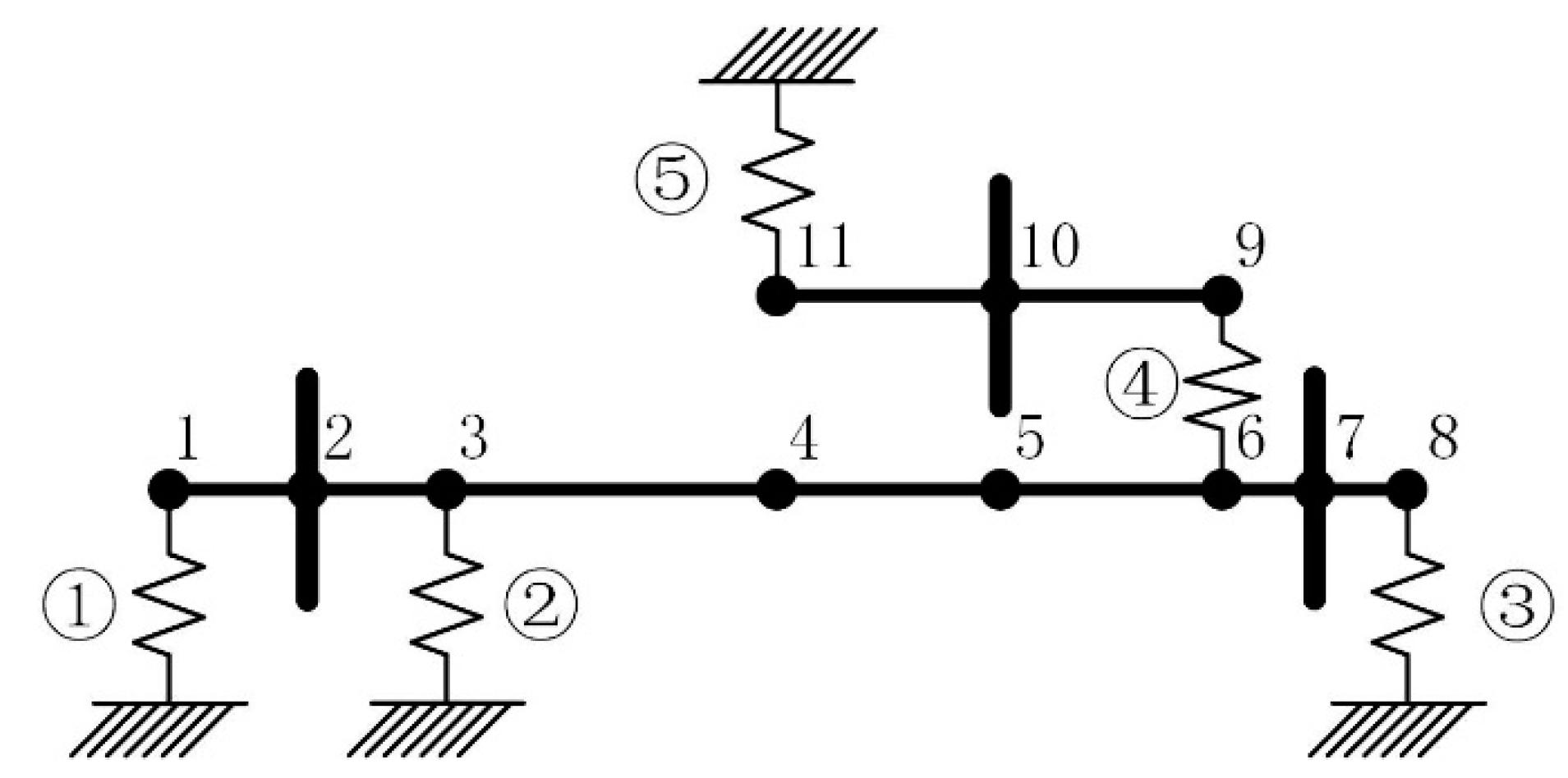
Compared with a co-rotating dual-rotor system, a counter-rotating system possess more modern industrial applications and has more complex dynamic properties. Thus, a counter-rotating dual-rotor system was selected as the research target for this paper. The rotating direction of the low-pressure rotor is the same as the positive direction of the axis according to the right-hand screw rule, whereas that of the high-pressure rotor is the opposite. It is defined as forward whirling when the direction of the whirling is the same as the rotating direction of the low-pressure rotor, and backward whirling otherwise. The finite element division of the dual-rotor-bearing system is shown in Figure 3. The physical parameters for the shaft segments, disks and bearings are summarized in Table 1, Table 2, Table 3 and Table 4.
3.1. Computation Method and Validation
From the results in Section 2.3.2, it is apparent that the mass, gyroscopic, damping and stiffing matrices on the left of the EOMs are constant and the forces on the right of the EOMs are constant or harmonic. Thus, the natural properties and responses of the linear dual-rotor system can be solved by direct matrix operations in the complex field.
Introducing a state-space vector and assuming that , the second-order homogeneous EOMs for the dual-rotor system with constant base rotations can be transformed into first-order state space form
The equivalent eigenvalue problem is
The solved and are the natural frequency and corresponding mode shape vector. For the constant forces assumed as , the responses are solved by
The harmonic forces assumed as can be rewritten in a complex field as
where is the imaginary unit. The steady-state solution is assumed to be
The harmonic responses are solved as
The results are the superposition of the constant and various harmonic responses.
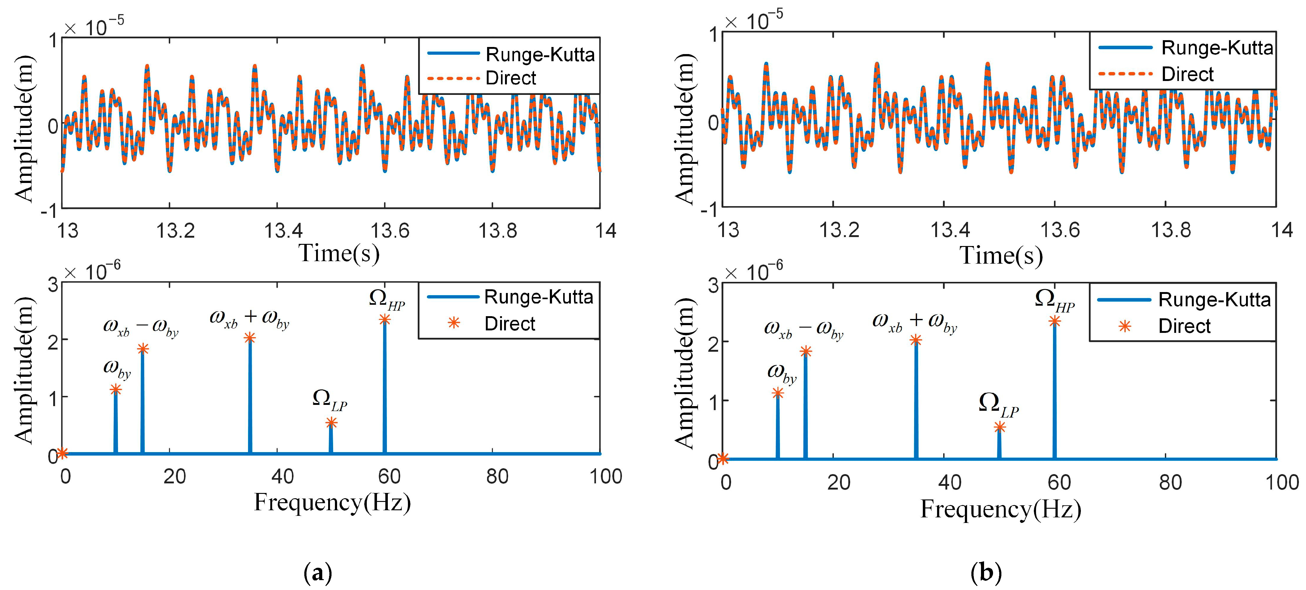
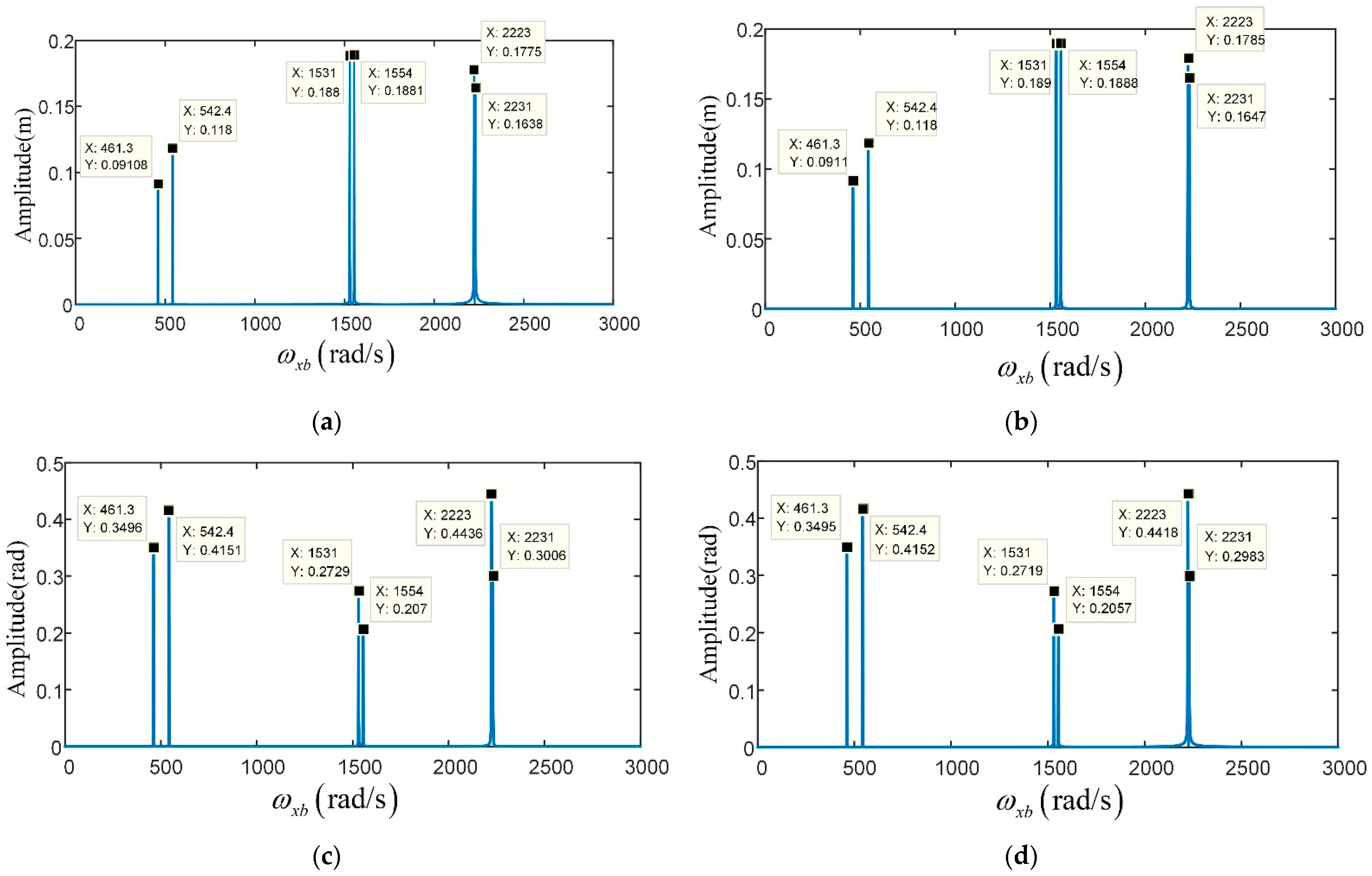
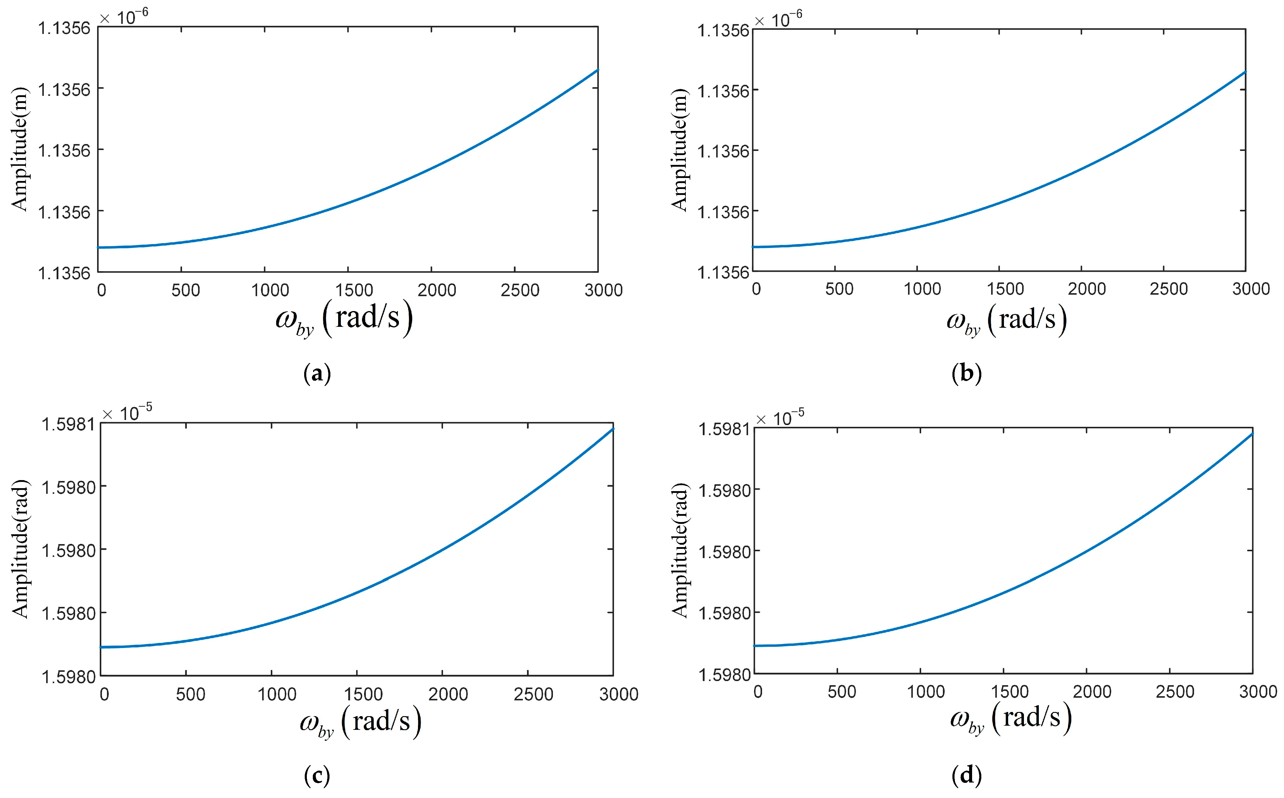
The accuracy of the above computation method is validated by comparison of the results solved by the Runge–Kutta numerical integration method. The base motions are set as , , , and , where , , . The rotation speeds of the dual-rotor system are set as , . The mass unbalances located on the three disks are set as . The results of disk 1 in both time and spectra domain are shown in Figure 4. By comparison, one can see that the results of two methods are in very good agreement with each other, verifying the accuracy of solving by direct matrix operation. The natural properties and harmonic responses of the counter-rotating dual-rotor system under constant base rotations are analyzed in following sections using direct computation method.
3.2. Natural Properties Influenced by Base Rotations
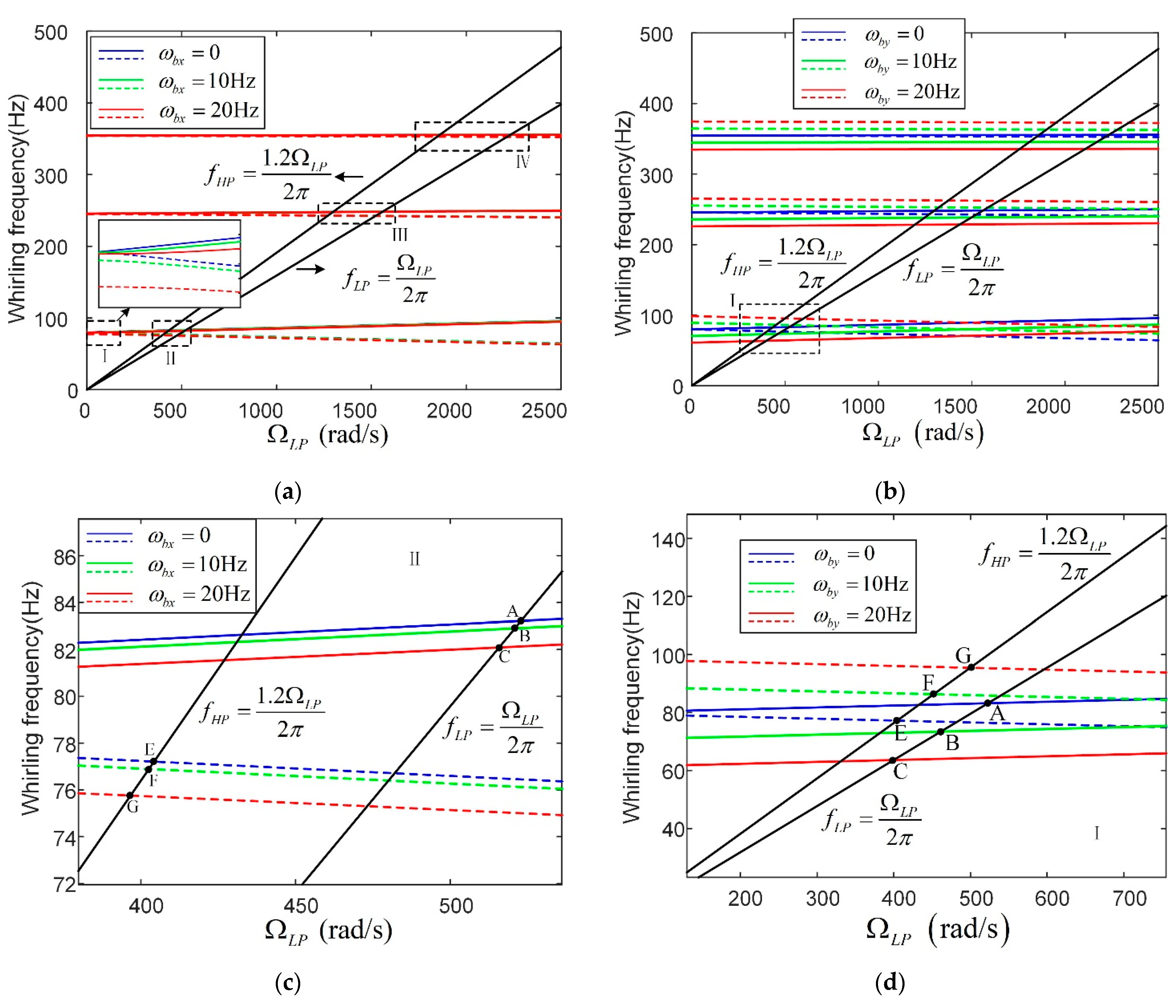
The influence of base rotations on the natural properties of a dual-rotor system are analyzed in this section. For a counter-rotating system, the rotating speed relationship between the two rotors was set at .
The Campbell diagrams with variable base rotations are summarized in Figure 5, where (a) and (c) represent the pitching base motion (), and (b) and (d) are for the rolling base motion (). As for the pitching base motion (), the overall effect was not strong. The limited differences showed that both the backward and forward whirling frequencies decreased with increasing base angular velocity (see zoom on Ⅰ and Ⅱ in (a) and (c)). Thus, the critical rotating speeds excited by unbalance decreased a little (see point A, B, C, D, E and F in (c)). Compared to the pitching base motion, the effect of rolling base motion was more noticeable. With increasing base angular velocity, the backward whirling frequencies increased while forward whirling frequencies decreased. In consequence, the critical speeds excited by the low-pressure rotor unbalance decreased, while the critical speeds excited by high-pressure rotor unbalance increased.
3.3. Forced Vibration Due to Mass Unbalance with Base Rotations
The influences of the constant base rotations on the mass unbalance responses of the dual-rotor system are analyzed in this section. As mentioned above, the rotation speed relationship between the rotors is set at .
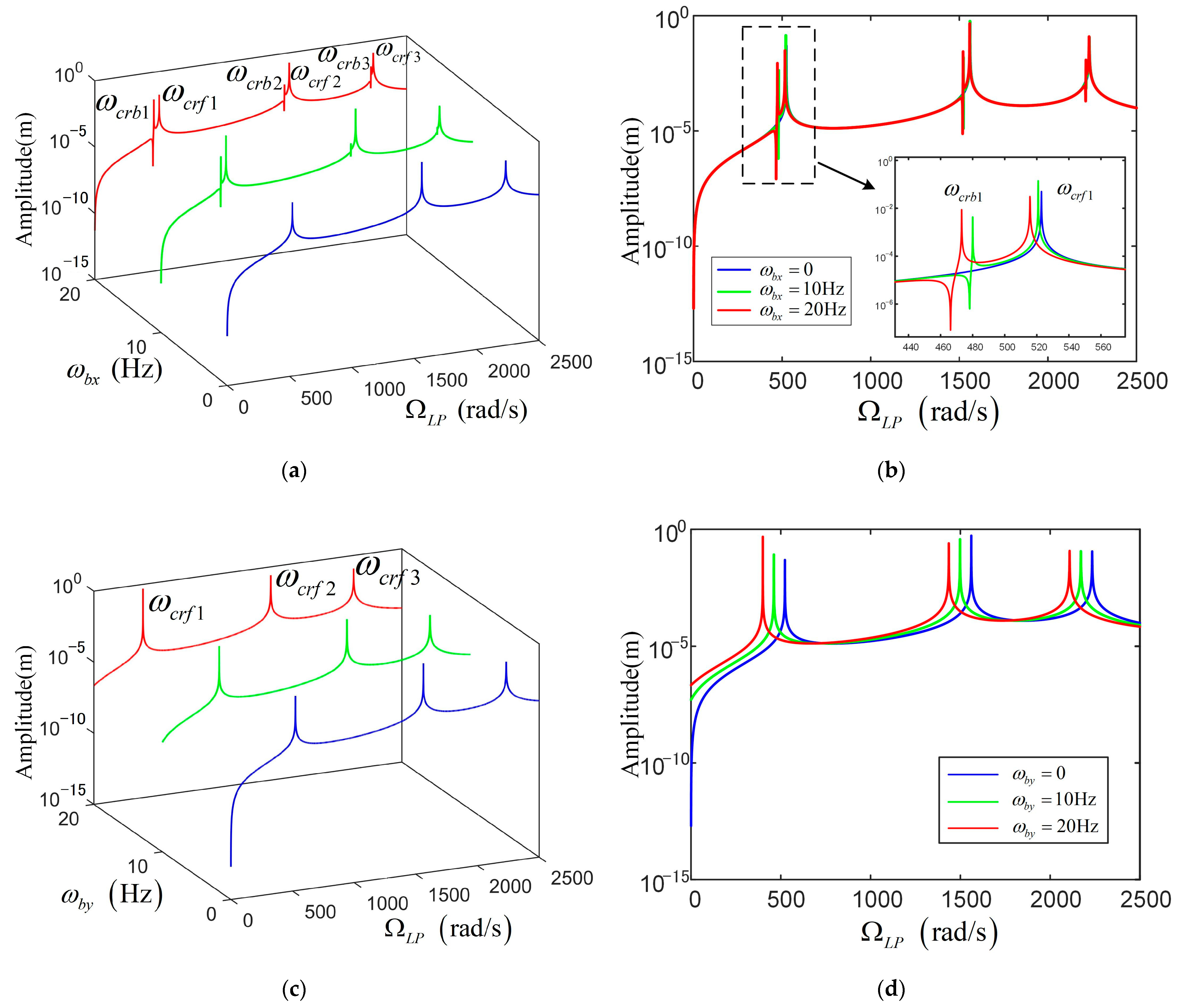
For the mass unbalance on a low-pressure rotor, the mass unbalances on the three disks are set as and . The frequency responses are shown in Figure 6. Only the forward whirling modes are excited when the base is fixed (see the blue lines). For the pitching base motion shown in Figure 6a,b, the backward whirling modes were also excited when the pitching base motion is concerned. The resonant frequencies decreased a little with increasing angular velocity of the pitching base motion. For the rolling base motion shown in Figure 6c,d, only the forward whirling modes were excited. The resonant frequencies decreased remarkably, when the angular velocity of the rolling base motion increased.
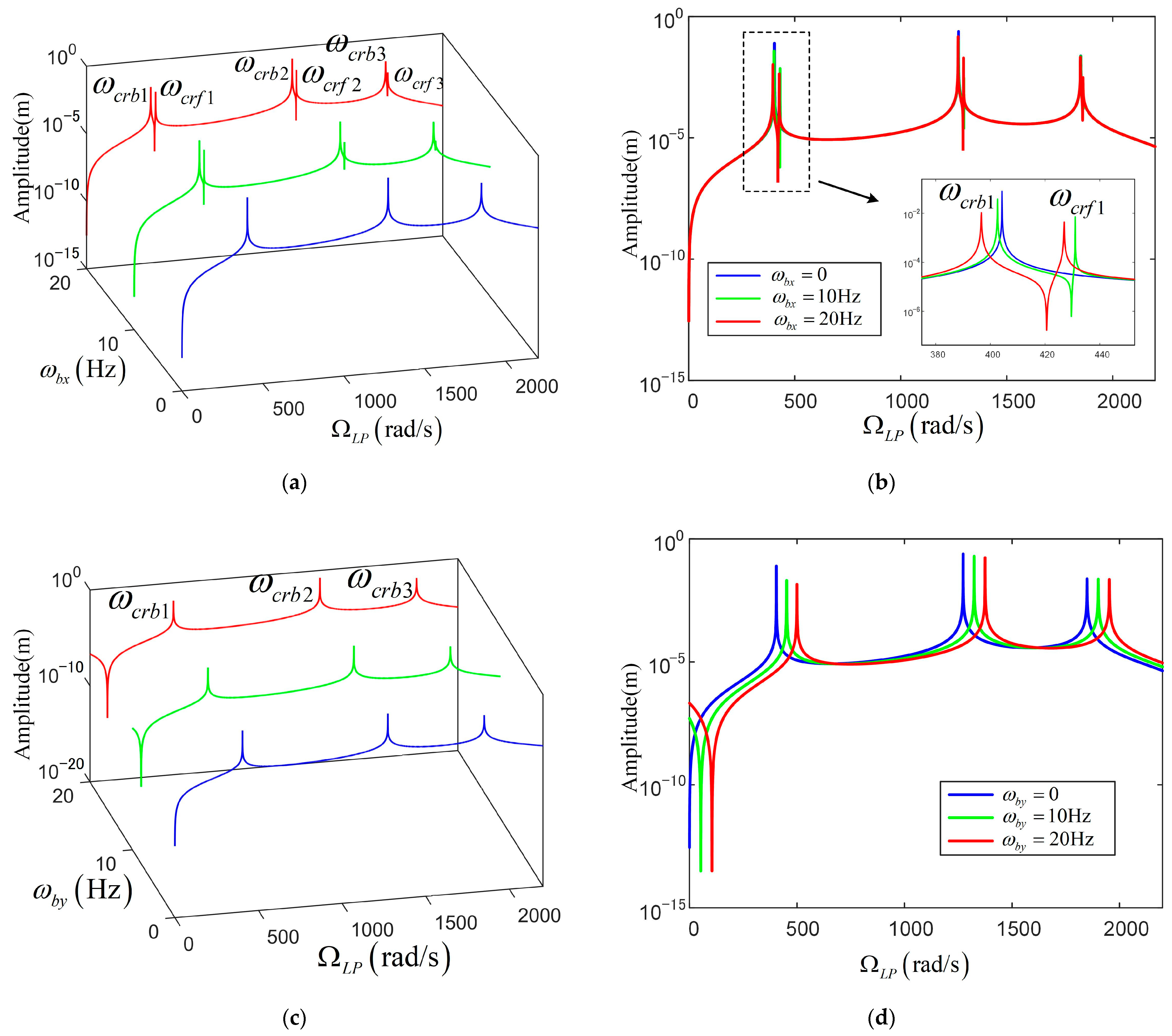
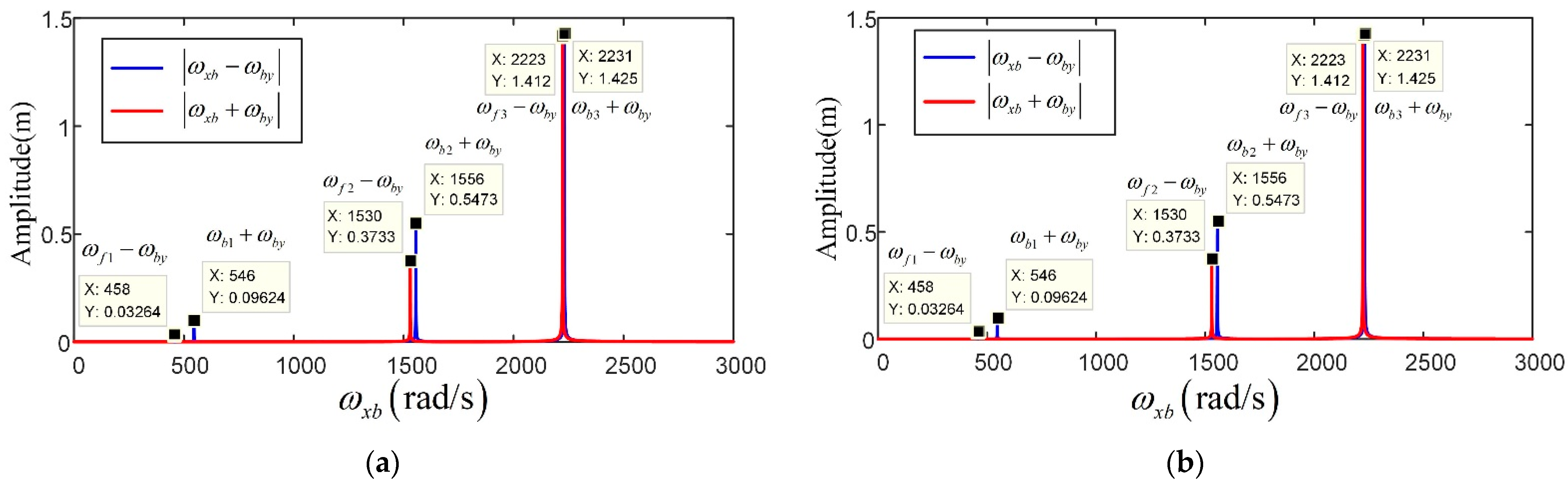
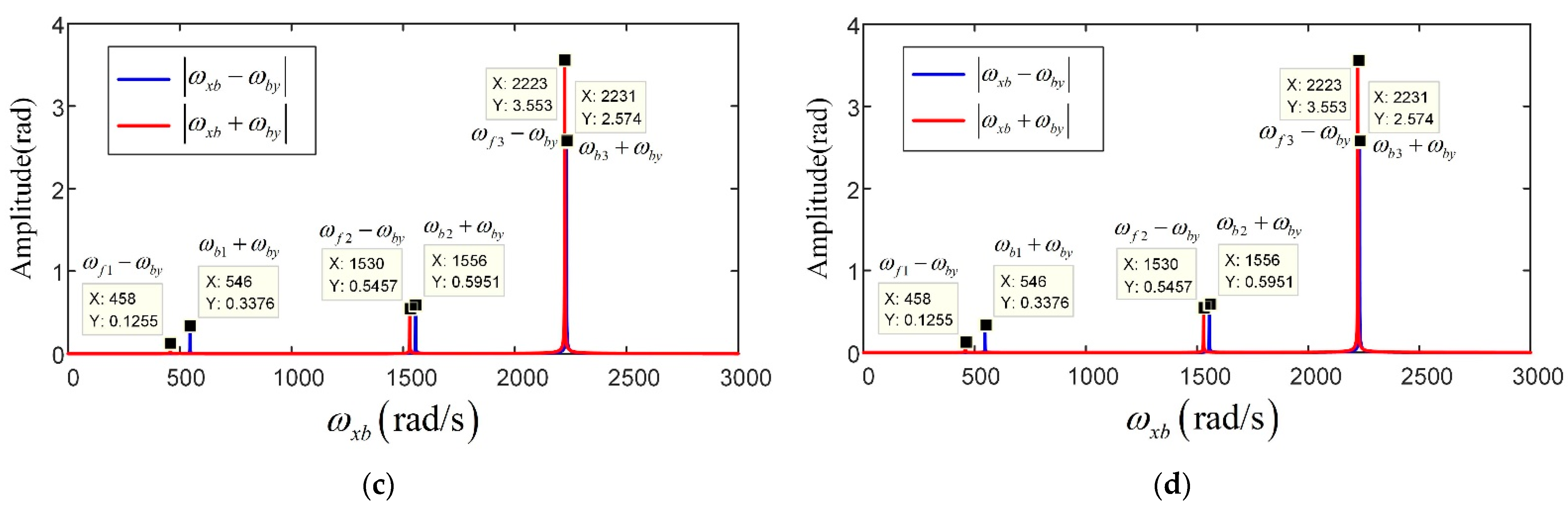
For the mass unbalance on a high-pressure rotor, the mass unbalances are set at and . The frequency responses are shown in Figure 7. Only the backward whirling modes were excited when the base was fixed (see the blue lines). For the pitching base motion shown in Figure 7a,b, the forward whirling modes were also excited when the pitching base motion was concerned. The resonant frequencies decreased a little with increasing angular velocity of the pitching base motion. For the rolling base motion shown in Figure 7c,d, only the backward whirling modes were excited. The resonant frequencies decreased remarkably, when the angular velocity of the rolling base motion increased.
Here are some explanations for the above phenomenon. When the base was fixed, the system possessed perfect symmetry along the two linear displacement directions ( and ). Even the amplitudes of the two components of the unbalance force along these directions were equal. Thus, the unbalanced force was only in accordance with whirling modes along one direction: backward for the mass unbalance on the low-pressure rotor and forward for the mass unbalance on the high-pressure rotor. The rolling base motion did not break this symmetry, and the amplitudes of the two components of the unbalance force remained equal (see Equations (32), (36), (39), (64), (65) and (70)). However, when the pitching base motion was involved, the stiffness symmetry along and was not maintained and the amplitudes of the two components of the unbalance force were not equal (see Equations (35), (58) and (63)).
3.4. Forced Vibration Due to Base Translations with Base Rotations
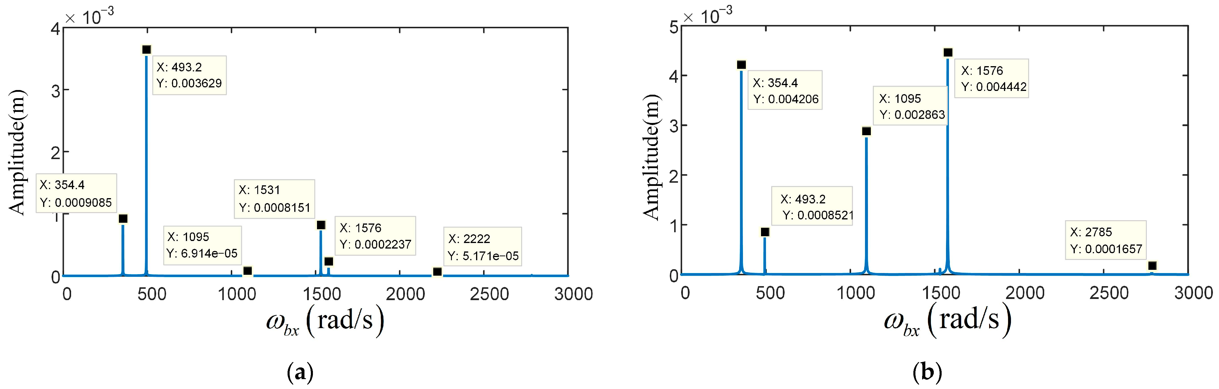
The influences of the base translations on the dual-rotor system are analyzed in this section. The counter-rotating dual-rotor system was taken as analysis target, and the rotating speeds of the LP and HP rotor were set at , . The natural frequencies were calculated first and listed in Table 5.
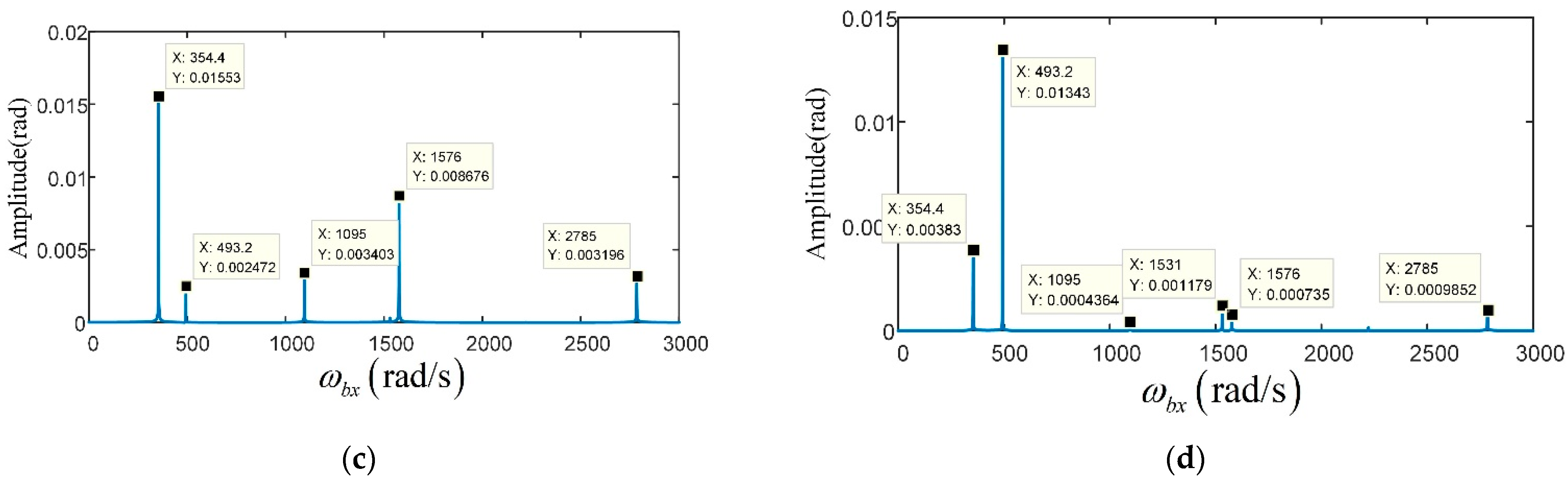
The base translations were assumed to be time-periodic: , and . The initial base angular angle was set to zero: . For the base translation along the , the base translation amplitude was set at . The harmonic responses of the disk 1 with and without base rotations are shown in Figure 8, Figure 9 and Figure 10. The results revealed that not only the forward whirling but also the backward whirling resonances could be excited by harmonic base translations, while some differences still merit attention. For the base translations with pitching base motion, the response amplitudes changed remarkably; however, the resonant frequencies had little distinction compared with the results without base rotations because the effects of the pitching base motion were applied through changes in the stiffness matrices and unbalance force amplitude (see Equations (58) and (63)). For the base translations with rolling base motion, the unbalance forces consisted of two frequencies: combined translation and rolling motion (see Equation (66)). Backward whirling modes could only be excited by part of the frequency , while forward whirling modes could only be excited by another part .
Here are some explanations for the above phenomenon. For the case of fixed base and pitching base motion, all components of additional forces changed as the cosine function of time (see Equation (59)). Thus, the excitation vector had components in accordance with all the whirling modes. However, in the case of rolling base motion, the two parts of the excitation vector only had components in accordance with backward whirling or forward whirling modes, respectively (see Equation (66)).
3.5. Forced Vibration Due to Gravity with Base Rotations
The influence of gravity on the dual-rotor system are analyzed in this section. For the counter-rotating system, the rotating speeds of the LP and HP rotors were set at and .
Gravity was constant and caused only constant displacements along its acting direction when the system was under a fixed base. It became a harmonic force with base angular frequency when the constant base rotations were concerned (see Equations (62) and (69)). The harmonic responses of the dual-rotor system due to gravity and constant base rotations are shown in Figure 11 and Figure 12. Both backward and forward whirling modes could be excited by gravity for the dual-rotor system with pitching base motion, but no resonance was excited with rolling base motion. The whirling frequencies changed with the value of base angular velocities as the additional stiffness and damping matrices were concerned with base angular velocities (see Equation (58), (64) and (65)).
4. Conclusions
The combined effects of base motions, mass unbalance and gravity on vibration properties of a counter-rotating dual-rotor system were studied in this paper for the first time. Some conclusions are summarized as follows:
- (1)
- Constant base rotations generated constant external stiffness and damping matrices, and so had some impact on its natural properties. The effects of rolling base motion are larger than that of pitching base motion.
- (2)
- When the base was fixed, mass unbalance on different rotors only excited whirling modes that were in the same direction with the rotor rotating. The constant pitching base motion caused other whirling modes to be excited by mass unbalance forces, while the constant rolling base motion did not.
- (3)
- Base translations can stimulate both backward and forward whirling modes of the counter-rotating dual-rotor system whether or not the constant pitching base motion was involved. It is interesting that when the constant rolling base motion and base translation along the horizontal direction were both taken into account, the combined frequencies of the base angular velocity and base translation frequency can induce different resonances.
- (4)
- Components along different directions of the gravity exhibited harmonic behavior when the constant base rotations were concerned. They can also excite different whirling modes, while one with rolling base motion did not. In addition, matrix transformation in a complex field was validated as a useful and efficient computing method.
Author Contributions
Conceptualization, L.C. and J.W.; methodology, L.C.; software, L.C.; validation, L.C. and Z.Z.; formal analysis, L.C.; investigation, L.C.; resources, L.C.; data curation, L.C.; writing—original draft preparation, L.C.; writing—review and editing, D.Z. and Z.Z.; visualization, Z.Z.; supervision, J.W.; project administration, J.W.; funding acquisition, D.Z. All authors have read and agreed to the published version of the manuscript.
Funding
This research was funded by the National Natural Science Foundation of China (grant numbers are 52175071 and 52105083); the major projects of aero-engine and gas turbines (grant number is J2019-I-0008-0008); the Innovation Centre for Advanced Aviation Power (grant number is HKCX2020-02-016).
Institutional Review Board Statement
Not applicable.
Informed Consent Statement
Not applicable.
Data Availability Statement
Not applicable.
Acknowledgments
Special thanks go to Donghai Jin for his encouragement and help in preparing of this article.
Conflicts of Interest
The authors declare no conflict of interest.
References
- Chen, L.Q.; Wang, J.J.; Han, Q.K.; Chu, F.L. Nonlinear dynamic modeling of a simple flexible rotor system subjected to time-variable base motions. J. Sound Vib. 2017, 404, 58–83. [Google Scholar] [CrossRef]
- Das, A.S.; Dutt, J.K.; Ray, K. Active vibration control of flexible rotors on maneuvering vehicles. AIAA J. 2010, 48, 340–353. [Google Scholar] [CrossRef]
- Das, A.S.; Dutt, J.K.; Ray, K. Active vibration control of unbalanced flexible rotor-shaft systems parametrically excited due to base motion. Appl. Math. Model. 2010, 34, 2353–2369. [Google Scholar] [CrossRef]
- Dakel, M.; Baguet, S.; Dufour, R. Steady-state dynamic behavior of an on-board rotor under combined base motions. J. Vib. Control 2014, 20, 2254–2287. [Google Scholar] [CrossRef] [Green Version]
- Dakel, M.; Baguet, S.; Dufour, R. Nonlinear dynamics of a support-excited flexible rotor with hydrodynamic journal bearings. J. Sound Vib. 2014, 333, 2774–2799. [Google Scholar] [CrossRef] [Green Version]
- Hori, Y.; Kato, T. Earthquake-induced instability of a rotor supported by oil film bearings. J. Vib. Acoust. 1990, 112, 160–165. [Google Scholar] [CrossRef]
- Lin, F.S.; Meng, G. Study on the dynamics of a rotor in a maneuvering aircraft. J. Vib. Acoust. 2003, 125, 324–327. [Google Scholar] [CrossRef]
- Xu, M.; Liao, M.F.; Liu, Q.Z. The vibration performance of the double-disk cantilever rotor in flight mission. J. Aerosp. Power 2002, 17, 105–109. [Google Scholar]
- Hou, L.; Chen, Y.S. Super-harmonic responses analysis for a cracked rotor system considering inertial excitation. Sci. China Technol. Sci. 2015, 58, 1924–1934. [Google Scholar] [CrossRef]
- Hou, L.; Chen, Y.S.; Lu, Z.Y.; Li, Z.G. Bifurcation analysis for 2: 1 and 3: 1 super-harmonic resonances of an aircraft cracked rotor system due to maneuver load. Nonlinear Dyn. 2015, 81, 531–547. [Google Scholar] [CrossRef]
- Wang, R.; Guo, X.L.; Wang, Y.F. Nonlinear analysis of rotor system supported by oil lubricated bearings subjected to base movements. Proc. Inst. Mech. Eng. Part C J. Mech. Eng. Sci. 2016, 230, 543–558. [Google Scholar] [CrossRef]
- Soni, A.H.; Srinivasan, V. Seismic analysis of a gyroscopic mechanical system. J. Vib. Acoust. Stress Reliab. Des. 1983, 105, 449–455. [Google Scholar] [CrossRef]
- Srinivasan, V.; Soni, A.H. Seismic analysis of a rotor-bearing system. Earthq. Eng. Struct. Dyn. 1984, 12, 287–311. [Google Scholar] [CrossRef]
- Samali, B.; Kim, K.B.; Yang, J.N. Random vibration of rotating machines under earthquake excitations. J. Eng. Mech. 1986, 112, 550–565. [Google Scholar] [CrossRef]
- El-Saeidy, F.M.A.; Sticher, F. Dynamics of a rigid rotor linear/nonlinear bearings system subject to rotating unbalance and base excitations. J. Vib. Control 2010, 16, 403–438. [Google Scholar] [CrossRef]
- Yang, Y.F.; Ren, X.M.; Qin, W.Y.; Wu, Y.F.; Zhi, X.Z. Analysis on the nonlinear response of cracked rotor in hover flight. Nonlinear Dyn. 2010, 61, 183–192. [Google Scholar] [CrossRef]
- Yang, Y.F.; Ren, X.M.; Qin, W.Y. Nonlinear response analysis of a cracked Jeffcott rotor in action of dive-hike. J. Vib. Shock 2007, 26, 21–24. [Google Scholar]
- Zhu, C.S.; Chen, Y.J. General dynamic model of aero-engine’s rotor system during maneuvering flight. J. Aerosp. Power 2009, 2, 020. [Google Scholar]
- Zhang, G.H.; Liu, S.P.; Ma, R.X.; Liu, Z.S. Nonlinear dynamic characteristics of journal bearing–rotor system considering the pitching and rolling motion for marine turbo machinery. Proc. Inst. Mech. Eng. Part M J. Eng. Marit. Environ. 2013, 229, 95–107. [Google Scholar]
- Duchemin, M.; Berlioz, A.; Ferraris, G. Dynamic behavior and stability of a rotor under base excitation. J. Vib. Acoust. 2006, 128, 576–585. [Google Scholar] [CrossRef]
- Driot, N.; Lamarque, C.H.; Berlioz, A. Theoretical and experimental analysis of a base-excited rotor. J. Comput. Nonlinear Dyn. 2006, 1, 257–263. [Google Scholar] [CrossRef]
- Driot, N.; Lamarque, C.H.; Berlioz, A. Dynamic of a rotor subjected to a base translational motion and an uncertain parametric excitation. In Proceedings of the 12th IFToMM World Congress, Besancon, France, 18–21 June 2007. [Google Scholar]
- Asgarisabet, M.; Ghazavi, M.R.; Shahgholi, M. Stability and bifurcations analysis of rotating shafts with base excitations. Nonlinear Dyn. 2014, 78, 2847–2859. [Google Scholar] [CrossRef]
- Han, Q.K.; Chu, F.L. Dynamic response of cracked rotor-bearing system under time-dependent base movements. J. Sound Vib. 2013, 332, 6847–6870. [Google Scholar] [CrossRef]
- Han, Q.K.; Chu, F.L. Parametric instability of flexible rotor-bearing system under time-periodic base angular motions. Appl. Math. Model. 2015, 39, 4511–4522. [Google Scholar] [CrossRef]
- Liu, Z.X.; Liu, Z.S.; Li, Y.; Zhang, G.H. Dynamics response of an on-board rotor supported on modified oil-film force considering base motion. Proc. Inst. Mech. Eng. Part C J. Mech. Eng. Sci. 2018, 232, 245–259. [Google Scholar] [CrossRef]
- Soni, T.; Dutt, J.K.; Das, A.S. Parametric stability analysis of active magnetic bearing supported rotor system with a novel control law subject to periodic base motion. IEEE Trans. Ind. Electron. 2019, 67, 1160–1170. [Google Scholar] [CrossRef]
- Soni, T.; Das, A.S.; Dutt, J.K. Active vibration control of ship mounted flexible rotor-shaft-bearing system during seakeeping. J. Sound Vib. 2020, 467, 115046. [Google Scholar] [CrossRef]
- Soni, T.; Dutt, J.K.; Das, A.S. Magnetic Bearings for Marine Rotor Systems—Effect of Standard Ship Maneuver. IEEE Trans. Ind. Electron. 2020, 68, 1055–1064. [Google Scholar] [CrossRef]
- Lee, A.S.; Kim, K.O.; Kim, Y.C. A finite element transient response analysis method of a rotor-bearing system to base shock excitations using the state-space Newmark scheme and comparisons with experiments. J. Sound Vib. 2006, 297, 595–615. [Google Scholar] [CrossRef]
- Sousa, M.S.; Del Claro, V.T.S.; Cavalini, A.A.; Steffen, V. Numerical investigation on the dynamic behavior of an onboard rotor system by using the fem approach. J. Braz. Soc. Mech. Sci. Eng. 2017, 39, 2447–2458. [Google Scholar] [CrossRef]
- Briend, Y.; Dakel, M.; Chatelet, E.; Andrianoely, M.A.; Dufour, R.; Baudin, S. Extended modal reduction for on-board rotor with multifrequency parametric excitation. J. Vib. Acoust. 2019, 141, 061009. [Google Scholar] [CrossRef]
- Briend, Y.; Dakel, M.; Chatelet, E.; Andrianoely, M.A.; Dufour, R.; Baudin, S. Effect of multi-frequency parametric excitations on the dynamics of on-board rotor-bearing systems. Mech. Mach. Theory 2020, 145, 103660. [Google Scholar] [CrossRef]
- Briend, Y.; Chatelet, E.; Dufour, R.; Andrianoely, M.A.; Legrand, F. Dynamics of on-board rotors on finite-length journal bearings subject to multi-axial and multi-frequency excitations: Numerical and experimental investigations. Mech. Ind. 2021, 22, 35. [Google Scholar] [CrossRef]
- Chen, X.; Gan, X.H.; Ren, G.M. Nonlinear responses and bifurcations of a rotor-bearing system supported by squeeze-film damper with retainer spring subjected to base excitations. Nonlinear Dyn. 2020, 102, 2143–2177. [Google Scholar] [CrossRef]
- Chen, X.; Gan, X.H.; Ren, G.M. Effect of flight/structural parameters and operating conditions on dynamic behavior of a squeeze-film damped rotor system during diving–climbing maneuver. Proc. Inst. Mech. Eng. Part G J. Aerosp. Eng. 2021, 235, 308–338. [Google Scholar] [CrossRef]
- Chen, X.; Gan, X.H.; Ren, G.M. Effects of journal static eccentricity on dynamic responses of a rotor system under base motions using FDM inertia model. J. Sound Vib. 2022, 519, 116591. [Google Scholar] [CrossRef]
- Hibner, D.H. Dynamic response of viscous-damped multi-shaft jet engines. J. Aircr. 1975, 12, 305–312. [Google Scholar] [CrossRef]
- Glasgow, D.A.; Nelson, H.D. Stability analysis of rotor-bearing systems using component mode synthesis. J. Mech. Des. 1980, 102, 352–359. [Google Scholar] [CrossRef]
- Li, D.F.; Gunter, E.J. A Study of the Modal Truncation Error in the Component Mode Analysis of a Dual-Rotor System. J. Eng. Power 1982, 104, 525–532. [Google Scholar] [CrossRef]
- Gupta, K.; Gupta, K.D.; Athre, K. Unbalance Response of a Dual Rotor System: Theory and Experiment. J. Vib. Acoust. 1993, 115, 427–435. [Google Scholar] [CrossRef]
- Ferraris, G.; Maisonneuve, V.; Lalanne, M. Prediction of the dynamic behavior of non-symmetrical coaxial co- or counter-rotating rotors. J. Sound Vib. 1996, 195, 649–666. [Google Scholar] [CrossRef]
- Chiang, H.D.; Hsu, C.; Tu, S. Rotor-Bearing Analysis for Turbomachinery Single- and Dual-Rotor Systems. J. Propuls. Power 2004, 20, 1096–1104. [Google Scholar] [CrossRef]
- Guskov, M.; Sinou, J.J.; Thouverez, F.; Naraikin, O.S. Experimental and Numerical Investigations of a Dual-Shaft Test Rig with Intershaft Bearing. Int. J. Rotating Mach. 2007, 2007, 075762. [Google Scholar] [CrossRef] [Green Version]
- Zhang, D.Y.; Liu, Y.H.; Liang, Z.C.; Ma, Y.H.; Hong, J. Prediction for critical speed of double spools system in aero engines. J. Propuls. Technol. 2015, 36, 292–298. [Google Scholar]
- Chen, X.; Liao, M.F. Steady-State Characteristics of a Dual-Rotor System with Intershaft Bearing Subjected to Mass Unbalance and Base Motions. In Turbo Expo: Power for Land, Sea, and Air, Proceedings of the ASME Turbo Expo 2018: Turbomachinery Technical Conference and Exposition, Oslo, Norway, 11–15 June 2018; American Society of Mechanical Engineers: New York, NY, USA, 2018. [Google Scholar]
- Chen, X.; Liao, M. TraAmerican Society of Mechanical Engineersnsient characteristics of a dual-rotor system with intershaft bearing subjected to mass unbalance and base motions during start-up. In Turbo Expo: Power for Land, Sea, and Air, Proceedings of the ASME Turbo Expo 2018: Turbomachinery Technical Conference and Exposition, Oslo, Norway, 11–15 June 2018; American Society of Mechanical Engineers: New York, NY, USA, 2018. [Google Scholar]
Figure 1.
A dual-rotor system on a moving base with various coordinate systems.

Figure 2.
Derivation of the linear and angular velocity of the disk: (a) Linear velocity of the disk; (b) Angular velocity of the disk.
Figure 2.
Derivation of the linear and angular velocity of the disk: (a) Linear velocity of the disk; (b) Angular velocity of the disk.

Figure 3.
The finite element model for the dual-rotor-bearing system: 1~11 are the serial numbers of nodes, ①~⑤ are the serial numbers of bearings.
Figure 3.
The finite element model for the dual-rotor-bearing system: 1~11 are the serial numbers of nodes, ①~⑤ are the serial numbers of bearings.

Figure 4.
Comparison of the Runge–Kutta method and direct matrix operation: (a) Displacement of the disk 1; (b) Displacement of the disk 1.
Figure 4.
Comparison of the Runge–Kutta method and direct matrix operation: (a) Displacement of the disk 1; (b) Displacement of the disk 1.

Figure 5.
Campbell charts of the counter-rotating dual-rotor system with variable base rotations: (a) Pitching base motion; (b) Rolling base motion; (c) Zoom on Ⅱ in (a); (d) zoom on Ⅰ in (b).
Figure 5.
Campbell charts of the counter-rotating dual-rotor system with variable base rotations: (a) Pitching base motion; (b) Rolling base motion; (c) Zoom on Ⅱ in (a); (d) zoom on Ⅰ in (b).

Figure 6.
Responses of the dual rotor system excited by mass unbalance on disk 2 with base motions: (a) Pitching base motion; (b) Pitching base motion; (c) Rolling base motion; (d) Rolling base motion.
Figure 6.
Responses of the dual rotor system excited by mass unbalance on disk 2 with base motions: (a) Pitching base motion; (b) Pitching base motion; (c) Rolling base motion; (d) Rolling base motion.

Figure 7.
Responses of the dual-rotor system excited by mass unbalance on disk 3 with base motions: (a) Pitching base motion; (b) Pitching base motion; (c) Rolling base motion; (d) Rolling base motion.
Figure 7.
Responses of the dual-rotor system excited by mass unbalance on disk 3 with base motions: (a) Pitching base motion; (b) Pitching base motion; (c) Rolling base motion; (d) Rolling base motion.

Figure 8.
Responses of the counter-rotating dual-rotor system at the disk 1 under harmonic base translations: (a) ; (b) ; (c) ; (d) .
Figure 8.
Responses of the counter-rotating dual-rotor system at the disk 1 under harmonic base translations: (a) ; (b) ; (c) ; (d) .

Figure 9.
Responses of the counter-rotating dual-rotor system under harmonic base translations and constant pitching base motion: (a) ; (b) ; (c) ; (d) .
Figure 9.
Responses of the counter-rotating dual-rotor system under harmonic base translations and constant pitching base motion: (a) ; (b) ; (c) ; (d) .

Figure 10.
Responses of the counter-rotating dual-rotor system under harmonic base translations and constant rolling base motion: (a) ; (b) ; (c) ; (d) .
Figure 10.
Responses of the counter-rotating dual-rotor system under harmonic base translations and constant rolling base motion: (a) ; (b) ; (c) ; (d) .


Figure 11.
Responses of the dual-rotor system at disk 1 due to gravity with pitching base motion: (a) ; (b) ; (c) ; (d) .
Figure 11.
Responses of the dual-rotor system at disk 1 due to gravity with pitching base motion: (a) ; (b) ; (c) ; (d) .


Figure 12.
Responses of the dual-rotor system at disk 1 due to gravity with rolling base motion: (a) ; (b) ; (c) ; (d) .
Figure 12.
Responses of the dual-rotor system at disk 1 due to gravity with rolling base motion: (a) ; (b) ; (c) ; (d) .


Table 1.
Shaft parameters for the dual-rotor-bearing system.
| Rotors | Node–Node | |||
|---|---|---|---|---|
| LP | 1–2, 2–3 | 75 | 0 | 6 |
| LP | 3–4 | 180 | 0 | 6 |
| LP | 4–5, 5–6 | 120 | 0 | 6 |
| LP | 6–7, 7–8 | 50 | 0 | 6 |
| HP | 9–10, 10–11 | 120 | 19.9 | 27.5 |
Table 2.
Disk parameters for the dual-rotor-bearing system.
| Rotors | Node | |||
|---|---|---|---|---|
| LP | 2, 7 | 0.7672 | 5.0924 × 10⁻⁴ | 9.9586 × 10⁻⁴ |
| HP | 10 | 0.1942 | 2.2109 × 10⁻⁴ | 4.3895 × 10⁻⁴ |
Table 3.
Bearing parameters for the dual-rotor-bearing system.
| Number | Node | ||
|---|---|---|---|
| 1 | 1 | 5 × 10⁷ | 100 |
| 2 | 2 | 5 × 10⁷ | 100 |
| 3 | 6, 9 | 5 × 10⁷ | 100 |
| 4 | 8 | 5 × 10⁷ | 100 |
| 5 | 11 | 5 × 10⁷ | 100 |
Table 4.
Material parameters of the shaft.
| Rotors | |||
|---|---|---|---|
| LP | 7800 | 2.06 × 10¹¹ | 0.3 |
| HP | 2800 | 7 × 10¹⁰ | 0.34 |
Table 5.
Natural frequencies of the counter-rotating dual-rotor system (rad/s).
| Orders | ||||||
|---|---|---|---|---|---|---|
| Without base rotations | 461.3 | 542.4 | 1530.7 | 1554.5 | 2223.5 | 2230.8 |
| With pitching base motion | 459.3 | 540.4 | 1530.0 | 1553.9 | 2223.0 | 2230.4 |
| With rolling base motion | 483.3 | 520.6 | 1492.7 | 1592.5 | 2168.2 | 2286.0 |
Publisher’s Note: MDPI stays neutral with regard to jurisdictional claims in published maps and institutional affiliations. |
© 2022 by the authors. Licensee MDPI, Basel, Switzerland. This article is an open access article distributed under the terms and conditions of the Creative Commons Attribution (CC BY) license (https://creativecommons.org/licenses/by/4.0/).
Share and Cite
MDPI and ACS Style
Chen, L.; Zeng, Z.; Zhang, D.; Wang, J. Vibration Properties of Dual-Rotor Systems under Base Excitation, Mass Unbalance and Gravity. Appl. Sci. 2022, 12, 960. https://0-doi-org.brum.beds.ac.uk/10.3390/app12030960
AMA Style
Chen L, Zeng Z, Zhang D, Wang J. Vibration Properties of Dual-Rotor Systems under Base Excitation, Mass Unbalance and Gravity. Applied Sciences. 2022; 12(3):960. https://0-doi-org.brum.beds.ac.uk/10.3390/app12030960
Chicago/Turabian StyleChen, Liqiang, Zhenkun Zeng, Dayi Zhang, and Jianjun Wang. 2022. "Vibration Properties of Dual-Rotor Systems under Base Excitation, Mass Unbalance and Gravity" Applied Sciences 12, no. 3: 960. https://0-doi-org.brum.beds.ac.uk/10.3390/app12030960
Note that from the first issue of 2016, this journal uses article numbers instead of page numbers. See further details here.