Article

Active Flutter Suppression and Aeroelastic Response of Functionally Graded Multilayer Graphene Nanoplatelet Reinforced Plates with Piezoelectric Patch

1
Beijing Key Laboratory of Nonlinear Vibrations and Strength of Mechanical Structures, Faculty of Materials and Manufacturing, Beijing University of Technology, Beijing 100124, China
2
Architecture and Civil Engineering Research Center, City University of Hong Kong Shenzhen Research Institute, Shenzhen 518057, China
3
Zhejiang Academy of Special Equipment Science, Hangzhou 310020, China
*
Author to whom correspondence should be addressed.
Submission received: 19 November 2021 / Revised: 11 January 2022 / Accepted: 14 January 2022 / Published: 25 January 2022
(This article belongs to the Special Issue Vibration Control and Applications)

Abstract

:
This paper investigates the aeroelastic flutter and vibration reduction of functionally graded (FG) multilayer graphene nanoplatelets (GPLs) reinforced composite plates with piezoelectric patch subjected to supersonic flow. Activated by the control voltage, the piezoelectric patch can generate the active mass and active stiffness that can accordingly increase the base plate’s stiffness and mass. As a result, it changes the GPLs reinforced plate’s dynamic characteristics. The motion equation of the plate-piezoelectric system is derived through the Hamilton principle. Based on the modified Halpin–Tsai model, the effects of graphene nanoplatelets weight fraction and distribution pattern on the dynamic behaviors of the plate are numerically studied in detail. The result illustrates that adding a few amounts of grapheme nanoplatelets can effectually enhance the aeroelastic properties of the plates. Two kinds of control strategies, including the displacement and acceleration feedback control, are applied to suppress the occurrence of the flutter of the plate. It shows that the displacement and acceleration feedback control can improve the critical flutter Mach number of the plate by attaching active stiffness and active mass, respectively. Furthermore, the combined displacement and acceleration feedback control has a better control effect than that of considering only one of them.

1. Introduction

Thin-walled structures with characteristics of lightweight, flexible, and low damping have been broadly applied in advanced aircraft. The increase of modern aircraft’s flight velocity causes the aeroelastic behaviors of these structures to be a significant concern. When the external skin of aircraft is subjected to complex aerodynamic flow conditions, the aeroelastic self-excited oscillation, termed the aeroelastic flutter, occurs. The large amplitude vibration produced by an aeroelastic flutter may lead to catastrophic consequences for aircraft. Hence, analysis of the aeroelastic flutter of panels under supersonic flow is important in designing and optimation of the supersonic aircraft vehicles’ external structures.
Aeroelastic flutter analysis is an important research branch of aerodynamics and is getting much more concern. Prakash and Ganapathi [1] investigated the supersonic flutter features of functionally graded plates based on the finite element procedure. The effects of different parameters, such as thermal gradient on aspect ratios, damping, and boundary conditions on the flutter behaviors were analyzed by solving the complex eigenvalue problem. Shin et al. [2,3] studied the aeroelastic and aero-thermoelastic flutter behaviors of the composite cylindrical panels and shells with viscoelastic layers under supersonic flows. Several types of damping treatments have been estimated and the results indicated that damping properties had important influences on the flutter boundaries of these sturctures. Chen et al. [4,5] investigated the nonlinear response and aeroelastic flutter of composite laminated plates and shells under the combined excitation of aerodynamic pressures and transverse excitation. Yang et al. [6] studied the supersonic flutter of laminated composite plate concluding a viscoelastic mid-layer and examined the influences of viscoelastic damping and aerodynamic damping on the flutter boundary of the plate. Singha and Mandal [7] numerically evaluated influences of the panel geometry, material parameters, boundary conditions, and airflow direction on the supersonic flutter characteristics and critical aerodynamic pressure of laminated composite cylindrical panels and plates. Lin et al. [8] proposed a theoretical model to analyze the nonlinear aeroelastic and random vibration of composite panels with shape memory alloy subjected to the thermal-aero-acoustic excitations.
Hence, flutter suppression became of particular interest and primary objective for aeroelastic investigation, considering its practical significance. Based on their proposed positive position feedback algorithm, Ferrari et al. [9,10] experimentally achieved an amplitude reduction of a free sandwich plate. Lee et al. [11,12] conducted theoretical and experimental investigations on the vibration control and performance of the aeroelastic stability of a rigid wing model attached with nonlinear energy sinks. Developing an adaptive output feedback controller, Reddy et al. [13] applied the control surface actuation of the leading edge and trailing edge to achieve the aeroelastic oscillation suppression of a nonlinear wing section. Lu et al. [14] proposed a robust control algorithm to enhance the aeroelastic performance of the composite laminated cantilever plates in a hygrothermal environment. Na et al. [15,16] applied a robust control strategy to suppress flutter and reduce the vibration amplitudes of an aeroelastic flapped wing system subjected to a pulse excitation in a supersonic flow. Utilizing a proportional derivative feedback approach, Oveisi and Nestorovic [17] investigated the active suppression of a nonlinear piezolaminated plate.
Piezoelectric material is one kind of smart material that has been widely utilized in active vibration suppression. Kasem and Dowell [18] investigated the aeroelastic stability and vibration characteristics of a plate with piezoelectric material. They concluded that the introduction of the piezoelectric effect could efficiently change the plate’s natural modes and aeroelastic modes. Li et al. [19,20,21] studied the aeroelastic flutter behavior and vibration control of supersonic beams and panels attached with piezoelectric materials. The results indicated that the aerodynamic performance of these structures could be greatly enhanced by considering the piezoelectric effects. According to a genetic algorithm, Song et al. [22] presented an optimal method to suppress the aeroelastic flutter of composite panels with smart piezoelectric under thermal effects. Oh and Lee [23] developed geometrically nonlinear finite elements for the aero-thermoelastic investigation of cylindrical piezoelectric laminated shells. They concluded that active piezoelectric actuation could efficiently improve the aerodynamic performance of the shell. Xue et al. [24] analyzed the oscillation reduction and static stability of a functionally graded piezoelectric plate under electro–mechanical excitations in a thermal environment. Results demonstrated that the volume fraction index of the plate’s material has an important influence on the vibration suppression performance. In order to control the flutter of a composite panel with piezoelectric actuators in supersonic airflow, Moon and Hwang [25] proposed an optimal control algorithm to improve the aeroelastic performance of the panel with a lower control input. Based on three different control strategies, Otiefy and Negm [26] utilized piezoelectric self-sensing actuators to reduce the flutter response of a transonic wing.
Graphene or graphene platelets (GPLs) are a kind of carbon-filled polymer composites that have extremely mechanical, electrical, and thermal properties and lower production costs. In addition, a large number of theoretical and experimental studies revealed that adding a low content of graphene into the pristine polymer matrix can significantly enhance its mechanical [27,28,29,30,31], thermal [32], and electrical properties [33]. Yang et al. [34] studied buckling and post-buckling characteristics of functionally graded multilayer composite beams reinforced with GPLs. Numerical results show that GPLs exhibited an excellent enhancement effect on the modulus and strength of beams and can increase the critical buckling load. Wang et al. [35] studied the influences of different GPL sizes on the mechanical properties of GPL nanocomposites. They concluded that a larger GPL size could dramatically increase the tensile modulus but decrease the nanocomposites’ strength. Song et al. [36,37] investigated the vibration characteristics, buckling, and dynamic responses of multilayer graphene nanoplatelet reinforced plates subjected to the combination of axial compression and transversal loads. Their study demonstrated that introducing a small amount of GPLs can remarkably enhance the beam’s buckling resistance and suppress oscillation response. Lin et al. [38] carried out an aeroelastic analysis of the dynamic behaviors of GPL plates subjected to in-plane excitations and applied voltage. Saidi et al. [39] analyzed the aeroelastic dynamics and stability of FG reinforced porous panels enclosed by piezoelectric layers subjected to supersonic airflow. Zhou et al. [40] investigated the dynamic response and flutter behavior of the graphene platelets reinforced porous panels in aerodynamic flow.
As reviewed above, the characteristics of structures made up of graphene reinforced composite materials have been extensively studied. The excellent properties of graphene provide us with new insights into the improvement of the aerodynamic performance of structures by adding graphene. Furthermore, the combined piezoelectric and graphene-reinforced materials make good candidates for the suppression of structural flutter. However, it seems to be limited for studies in the field of aeroelastic flutter and vibration reduction of plates consisting of graphene reinforced composite and piezoelectric patch.
To fill the aforementioned gap, the aeroelastic flutter properties of functionally graded GPLs reinforced composite plate are studied in the present study. The modified Halpin–Tsai model is utilized to calculate the material parameters. On the basis of the von-Karman geometry theory and first-order piston theory, the governing equations of GPLs plates with a piezoelectric patch are derived by Hamilton’s principle. The influences of GPLs distribution pattern and weight fraction of GPLs on critical flutter point are analyzed. According to the feedback method, the active vibration suppression is numerically investigated. The influence of feedback gain on flutter boundaries and the response near the critical flutter point is discussed in detail.

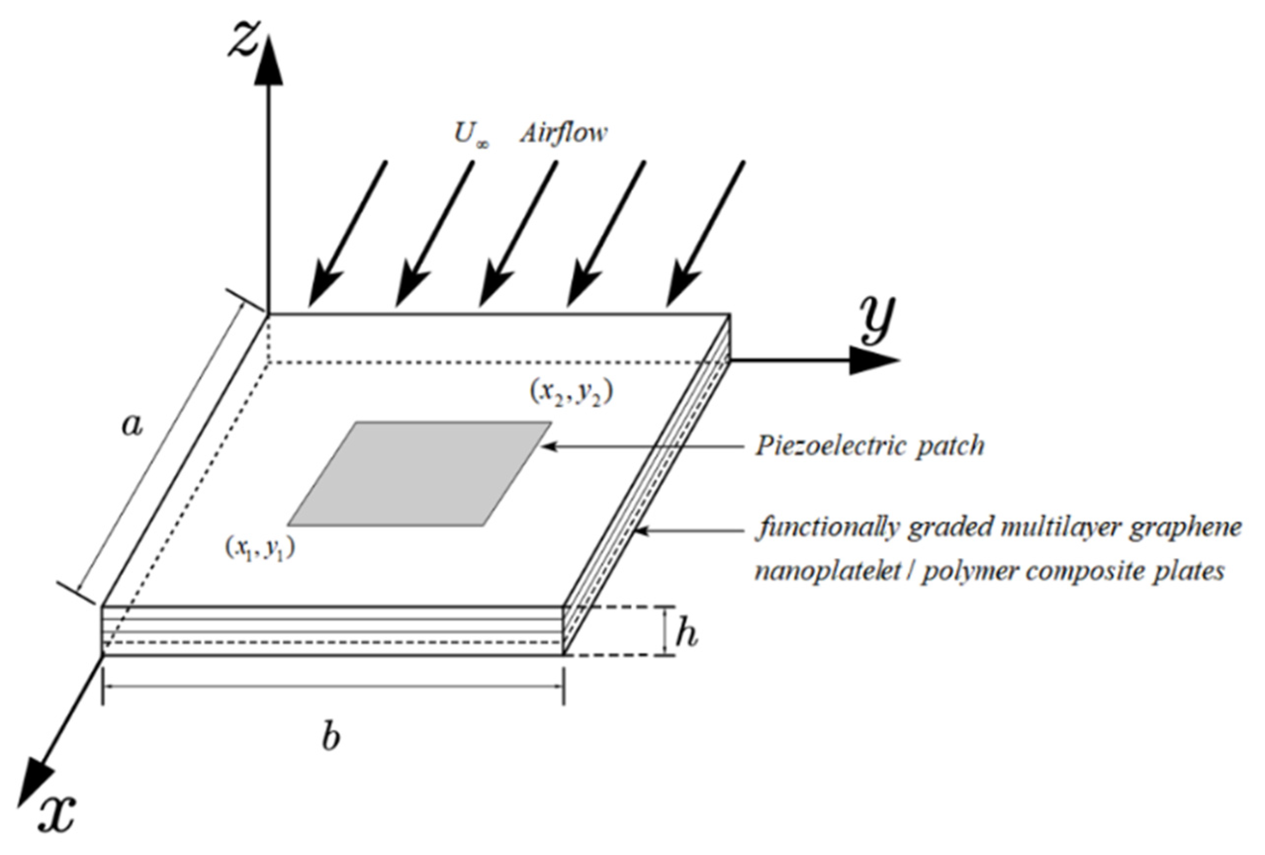
2. Problem Formulation

Figure 1 shows a functionally graded graphene composites plate attached with a piezoelectric patch. This plate and piezoelectric patch system consist of the base plate and the piezoelectric patch, which was used for vibration control. Simply supported at four edges, the rectangular plate was subjected to the supersonic flow where the incoming flow speed is expressed as U . Here, a , b and h represent the length, width, and thickness of the base plate.
Assuming the volume fraction of the GPLs linearly changes from layer to layer along with the thickness direction of the plate, two kinds of GPLs distribution patterns are considered in the present study— O-GPLs and X-GPLs distribution pattern—as shown in Figure 2. The O-GPLs distribution pattern means the GPL content reduces from the highest on plate’ midplane of the to the lowest on plate’s top and bottom surfaces. In comparison, the GPL content in the X-GPLs distribution pattern augments from the midplane to the top and bottom surfaces.
The modified Halpin–Tsai model was utilized to calculate the effective Young’s modulus of the GPL composite. Assume that the GPLs are effective rectangular solid fillers and uniformly dispersed in a polymer matrix. Consequently, the effective Young’s modulus E c of the GPLs can be approximately obtained by the Voigt Reuss model [37]
E c = 3 8 E Δ + 5 8 E
where E Δ is the longitudinal modulus, and E is the transverse modulus. They can be determined by Halpin—Tsai model
E Δ = 1 + ξ L η L V G P L 1 η L V G P L × E M ,             E = 1 + ξ W η W V G P L 1 η W V G P L × E M
Substituting Equation (2) into Equation (1) yields
E c = 3 8 1 + ξ L η L V G P L 1 η L V G P L × E M + 5 8 1 + ξ W η W V G P L 1 η W V G P L × E M
where
η L = ( E G P L / E M ) 1 ( E G P L / E M ) + ξ L ,           η W = ( E G P L / E M ) 1 ( E G P L / E M ) + ξ W
where E G P L and E M denote the Young’s moduli of the GPLs and polymer matrix, respectively. V G P L means the volume fraction of GPLs. ξ L and ξ W are the geometry and size parameters of GPL nanofillers, which can be expressed as
ξ L = 2 ( l G P L h G P L ) ,           ξ W = 2 ( w G P L h G P L )
in which l G P L , w G P L and h G P L represent the average length, width, and thickness of the GPLs, respectively. Mass density ρ c and Poisson’s ratio μ c of the GPL composite can be calculated by rule of mixture
ρ c = ρ G P L V G P L + ρ M V M ,           μ c = μ G P L V G P L + μ M V M
in which V M represents the volume fraction of polymer matrix, subscripts “ G P L ”, “ M ” and “ c ” respectively stand for GPLs, polymer matrix, and GPL composite.
The volume fraction of GPLs V G P L is given as
V G P L = g G P L g G P L + ( ρ G P L / ρ M ) ( 1 g G P L )
where g G P L is the weight fraction of GPLs in the nanocomposite.
The strain-displacement relationships of the base plate are presented as
ε 11 = z 2 w x 2 ,             ε 12 = 2 z 2 w x y ,             ε 22 = z 2 w y 2
where ε 11 , ε 22 and ε 12 are strains in x and y direction and the shear strain, respectively. w is the transverse displacement of the middle surface of the plate. On the basis of Generalized Hooke’s Law, the relationship between strains and stresses is obtained
σ 11 = E c 1 υ c 2 ( ε 11 + υ c ε 22 ) ,           σ 11 = E c 1 υ c 2 ( ε 22 + υ c ε 11 ) ,           σ 12 = G ε 12
where σ 11 , σ 22 and σ 12 , respectively, represent the normal stress components in x- and y- direction and shear stress component. E c , υ c , and G = E c / 2 ( 1 + υ c ) stand for the material’s modulus of elasticity, Poisson’s ratio, and shearing modulus, respectively.
The outer voltage is applied across the piezoelectric layer thickness. The relationship of strains and stresses for the piezoelectric patch can be expressed as
σ 11 p = c 11 ε 11 + c 12 ε 12 e 31 E 3 , σ 22 p = c 12 ε 11 + c 11 ε 12 e 31 E 3 σ 12 p = c 66 ε 12 , D 3 = e 31 ( ε 11 + ε 22 ) + 33 E 3
where σ 11 p , σ 22 p and σ 12 p represent the stress components. The elastic parameters c 11 , c 12 and c 66 can be expressed as c 66 = ( c 11 c 22 ) / 2 . e 31 and e 33 are the piezoelectric and coefficient, respectively. V 0 ( t ) represents the external applied voltage, and h p is the thickness of the piezoelectric layer. D 3 denotes the electric displacement, E 3 = V 0 ( t ) / h p means the electric intensity along the z-direction [41,42].
Considering the kinetic energies of the base plate and the piezoelectric layer, and neglecting the influence of rotatory inertia of thin plates considered herein [21], the total kinetic energy for the plate and piezoelectric layer system are obtained as
T = 1 2 V ρ c w ˙ 2 d v + 1 2 V p ρ p w ˙ 2 d v
where the dot denotes the differentiation with respect to the time. ρ c and ρ p , respectively, stand for the base plate’s and piezoelectric layer’s mass densities. V and V p represent the plate’s and piezoelectric layer’s volumes, respectively.
The total potential energy of the plate and piezoelectric patch system includes the strain energy of the base plate, The potential energy of the piezoelectric layer concludes the piezoelectric layer’s strain energy and electric potential energy. Therefore, the total potential energy of the plate and piezoelectric patch system can be obtained as
U = 1 2 V σ 11 ε 11 + σ 22 ε 22 + σ 12 ε 12 d v + 1 2 V p σ 11 p ε 11 + σ 22 p ε 22 + σ 12 p ε 12 d v 1 2 V p D 3 E 3 d v
The virtual work includes the effects of the external applied forces and the aerodynamic pressure, which are given as
δ W = A q δ w + Δ p δ w d A
where A is the plate’s surface area, q is the distributed load per unit area of the plate surface. On the basis of the supersonic piston theory [1,2,23], the aerodynamic load Δ p are obtained as
Δ p = ζ w x μ w t
where μ = ρ U ( M a 2 2 ) / M a 2 1 ( M a 2 1 ) is the aerodynamic damping parameters, ζ = ρ U 2 / M a 2 1 is the aerodynamic parameters. ρ , U and M a represent the free stream air density, velocity, and Mach number, respectively.
The transverse displacements variables w can be assumed in terms of mode shape and generalized coordinates
w ( x , y , t ) = i = 1 m j = 1 n W i j ( x , y ) r i j ( t ) = W T ( x , y ) r ( t )
where vector r ( t ) = [ r 11 r 1 n ,     r 21 r 2 n , ,   r m 1 r m n ] T denotes the generalized coordinate, and vector W ( x , y ) = [ w 11 w 1 n ,     w 21 w 2 n , ,   w m 1 w m n ] T means the mode shape function.
The mode shape of the four edges simply supported rectangular plates are presented as
w i j = sin i π x a sin j π y b ( i = 1 , , m ;     j = 1 , 2 , n )
Substituting Equations (8)–(10), and Equations (14)–(16) into Equations (12) and (13), and applying Hamilton’s principle, the governing equation the functionally graded multilayer graphene nanoplatelet composite plate with piezoelectric layer are derived as
M   r ¨ + ( F Δ p 2 T ) r ˙ + ( K 1 F Δ p 1 T ) r + V 0 K 2 = q F q
where M denotes the mass matrix of the base plate and piezoelectric patch system, K 1 represents the stiffness matrix of the base plate and piezoelectric layer, K 2 stands for the electromechanical coupling matrix of the piezoelectric layer, F q is the forcing matrices. Corresponding to the aerodynamic pressure Δ p , F Δ p 1 and F Δ p 2 represent the aerodynamic matrix and aerodynamic damping matrix of the base plate, respectively. The expression of these matrices is given in Appendix A.
Equation (17) is the motion equation of the actuator. It indicates that the piezoelectric actuator could be driven through the externally applied voltage V 0 , which relates to the structural deformation. Based on this equation, the active aeroelastic flutter of the supersonic plate attached with a piezoelectric layer was investigated through the displacement and acceleration feedback approach.

3. Flutter Analysis

As indicated in Equation (17), the applied voltage that is acted to the piezoelectric actuator can generate the base plate’s transverse displacement and acceleration. Meanwhile, the measured transverse displacement and acceleration, in turn, provided the feedback information for the piezoelectric actuator. Then, a control algorithm was utilized to control the vibration of the plate based on the feedback information. The activated piezoelectric layer, therefore, can provide the active stiffness and active mass to the base plate by the appropriate control voltage. Based on reference [21], the control voltage exerted to the piezoelectric actuator at the position ( x 0 , y 0 ) are derived in terms of the transverse displacement and acceleration
V 0 ( t ) = K d w ( x 0 ,   y 0 ,   t ) K a w ¨ ( x 0 ,   y 0 ,   t )
where K a and K d are the acceleration and displacement feedback gain of the piezoelectric actuator, respectively.
Substituting the expression of W ( x , y ) into Equation (18), and then substituting the resultant expression of voltage V 0 ( t ) into the actuator Equation (17), the motion equation of the plate with the active stiffness and mass is resented as
( M   +   M p ) r ¨ + ( - F Δ p 2 ) r ˙ + ( K 1 + K p - F Δ p 1 ) r = q F q
where M p and K p are the active mass and active stiffness matrices related to the piezoelectric layer, which can be obtained as
M p = K a K 2 W T ( x 0 , y 0 ) ,   K p = K d K 2 W T ( x 0 , y 0 )
Equation (19) demonstrates the displacement and acceleration feedback control strategy can provide the active stiffness and active mass to the base plate, respectively. By varying the feedback gain of K a and K d , the active mass M p and the active stiffness K p are accordingly added to the structure. As a result, it will change the structural nature frequency and damping ratio, which correspondingly alters the structural aeroelastic characteristics. This phenomenon can be observed in the following Section 4 that the active mass and stiffness can effectively enhance the plate’s aeroelastic flutter characteristics in supersonic flow.
The general solution of Equation (20) can be presented as
r ( t ) = r 0 e λ t
where r 0 and λ represent the eigenvector and eigenvalue of the system. Substituting Equation (21) into the homogeneous differential Equation (19) results in the following eigenvalue problem
[ ( M   +   M p ) λ 2 F Δ p 2 λ + ( K 1 + K p - F Δ p 1 ) ] r = 0
The nontrivial solution of Equation (22) can be obtained by solving its eigenvalues problem. The solution of the eigenvalue is a complex number that is obtained as
λ i = η i + i ω i
where η i is the parameter with respect to the damping ratio ξ i and eigenfrequency ω i by η i = ζ i ω i , and i = 1 . Calculating the complex eigenvalues problem of the system, the active aeroelastic flutter properties of the plate with the piezoelectric layer can be numerically analyzed.
The non-dimensional flutter velocity is usually obtained in the form of the non-dimensional aerodynamic pressure [2,43]. However, the variation of the weight fraction of GPLs will change the Young’s modulus of a material, which will accordingly alter the non-dimensional aerodynamic pressure. It indicates that the non-dimensional aerodynamic pressure cannot linearly reflect the change of aerodynamic pressure, so the non-dimensional flutter velocity in this paper is obtained in terms of the Mach number.
Increasing of Mach number M a , two consecutive eigenfrequencies ω i in the imaginary part of eigenvalues will approach each other and coalesce at a certain Mach number M a . It is termed as the critical Mach number M a c at which the flutter occurs. Besides, we can also consider the real part of eigenvalues η i which will become greater than zero as the aeroelastic flutter happens [35].
The following analysis mainly focused on the active aeroelastic flutter characteristics of the GPLs reinforced plate with a piezoelectric patch. Therefore, the externally applied force q in Equation (19) can be neglected.

4. Numerical Result

4.1. Comparison Study

The validity of the present formulations was verified by the comparison of the obtained dimensionless frequencies with those in the literature [37,44], as demonstrated in Table 1. The dimensionless frequencies ω ¯ = ω h ρ M / E M of a simply supported functionally graded GPLs reinforced composite plate are compared with the work by Song et al. [37] and the finite element method based on ANSYS [44]. The geometrical and material parameters of the GPLs plate involved in the comparison are the same as those of Ref. [37]. A good agreement can be found for the dimensionless frequencies obtained in the present study and those reported in the open literature. This comparative study demonstrates the accuracy of the present analysis.

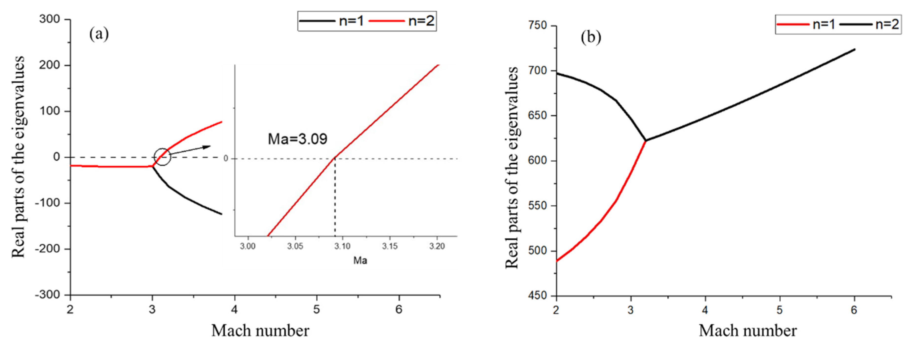
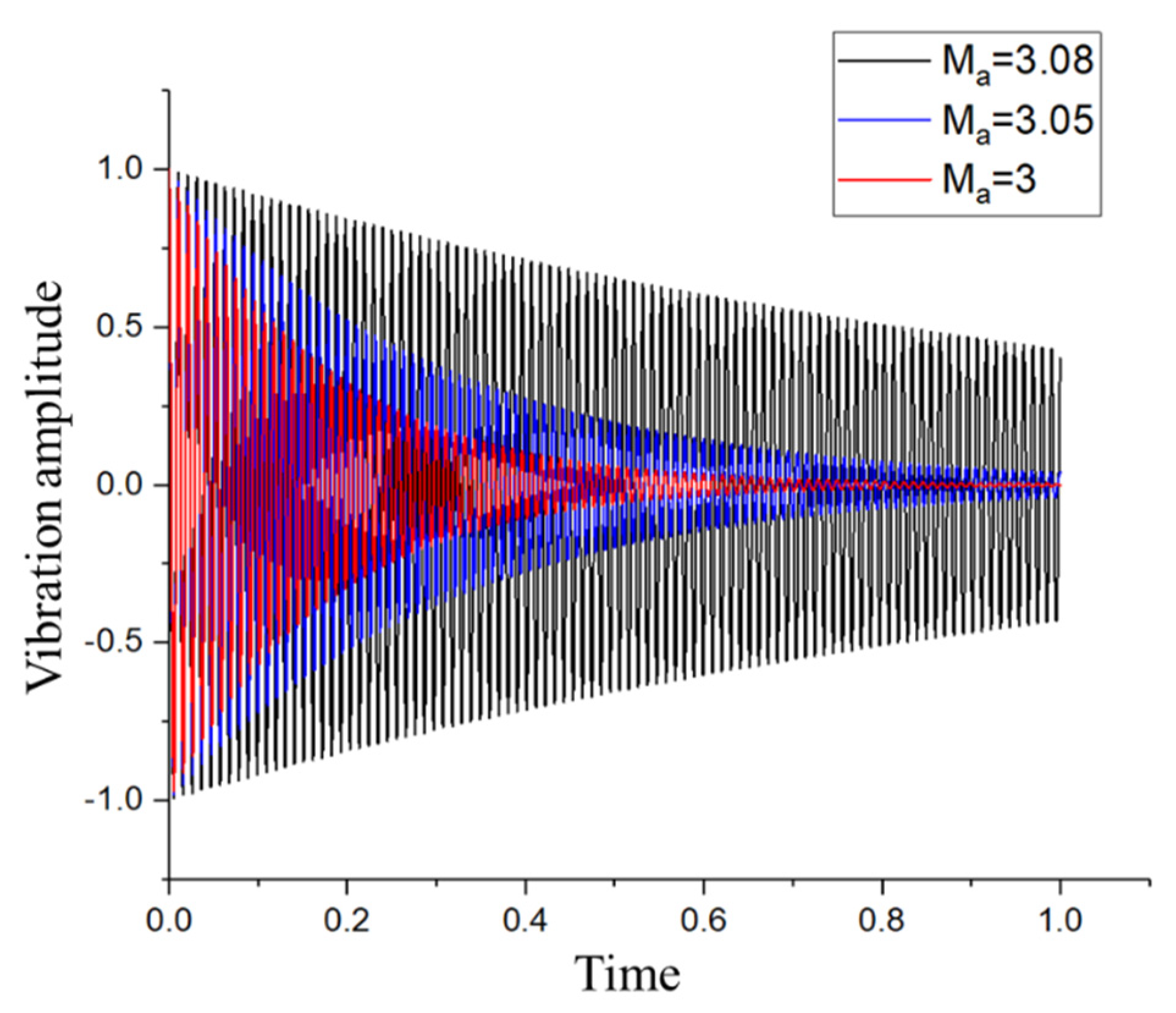
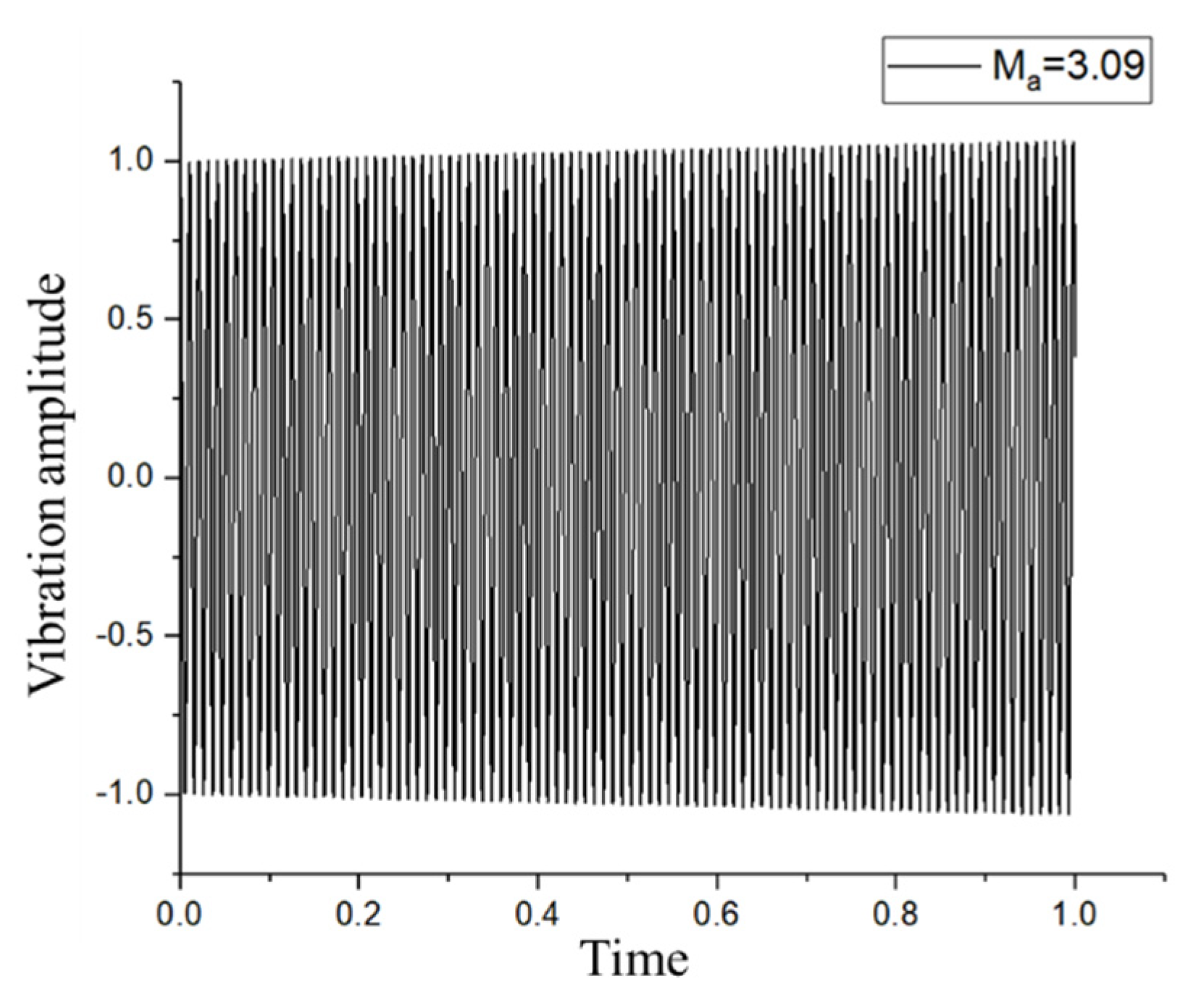
4.2. Vibration Characteristics

The effects of graphene material parameters, including GPLs distribution pattern and GPLs weight fraction, on the vibration characteristics of the functionally graded GPLs reinforced composite plate are investigated. The geometrical and material parameters of the plate are given as a = 0.6   m , b = 0.4   m , h = 0.006   m , l G P L = 2.5   μ m , w G P L = 1.5   μ m , h G P L = 1.5   μ m , υ M = 0.34 , υ G P L = 0.186 , ρ M = 1200   kg / m 3 , ρ G P L = 1062   kg / m 3 , E M = 3   GPa , N L = 10 , E G P L = 1010   GPa .
Figure 3 shows the changes of the dimensionless frequency with the increase of the weight fraction of GPLs for two kinds of GPLs distribution patterns. Herein, the abscissa denotes the GPLs weight fraction, while the ordinate denotes the relative frequency change rate, which is expressed as ( ω ω M ) / ω M × 100 % . It was introduced to present the variation of the frequency of plate after adding GPLs reinforcement, where ω M is the dimensionless frequency of pure epoxy polymer, ω represents the frequency of the plate after adding GPLs reinforcement.
It can be found from Figure 3 that with the increment of the GPLs weight fraction, the relative frequency change rate augments and keep positive for both the X-GPLs distribution pattern and the O-GPLs distribution pattern. This indicates that introducing GPLs reinforcement can raise the plate’s frequencies. Besides, the GPLs distribution pattern also can affect the vibration characteristics of the plate. Compared with the O-GPLs distribution patterns, the X-GPLs distribution pattern leads to a more dramatic improvement of the relative frequency change. It implies that the X-GPLs distribution pattern has a better effect on the increase of the plate’ frequencies than the O-GPLs distribution patterns. It is attributed to the fact that the X-GPLs distribution patterns can make better use of the high Young’s modulus GPLs reinforcement, hence, lead to a greater increment in the stiffness of the plate [37].
It is known that plates with greater stiffness often have better aerodynamic performance when they are subjected to aerodynamic load [38]. Figure 4 shows the effect of GPLs weight fraction on the critical Mach number for the occurrence of flutter of the GPLs reinforced plate. It illustrates that increasing the GPLs’ weight fraction will increase the critical flutter Mach number of the plate, which means that adding graphene can effectively suspend the flutter of plates happening. In Figure 4, the critical Mach number that is less than or equal to 1.5, is presented as equal to 1.5, as the first-order piston theory is only applicable as the speed of the airflow is above the Mach number of 1.5 [45]. It also can be observed from Figure 4 that when the GPLs weight fraction keeps increasing, both O-GPLs distribution and X-GPLs distribution will result in the increment of the critical Mach number of the GPLs plates. However, the critical Mach number for X-GPLs distribution is greater than the critical Mach number for O-GPLs distribution under the same value of the GPLs weight fraction.
Thereby, it indicates that graphene has a reinforcing effect on the aerodynamics of the plate, as it can increase the critical flutter Mach number of the plate. In addition, the X-GPLs distribution has better effects than the O-GPLs distribution.

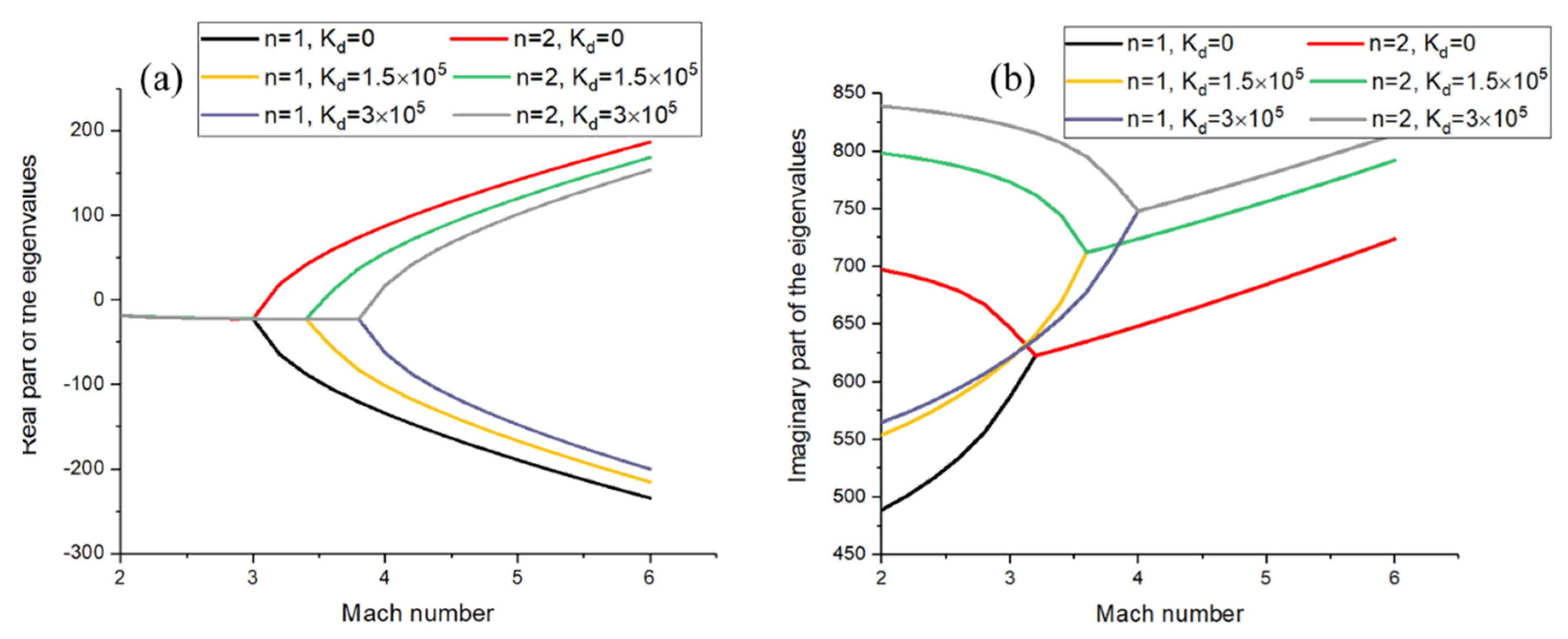
4.3. Flutter Suppression

In this subsection, the aeroelastic flutter and the vibration suppression were further studied for a GPLs reinforced composite plate attached with a piezoelectric patch under supersonic flow. As shown in Figure 1, the piezoelectric actuator and sensor were located at the center of the rectangular base plate. The weight fraction of the GPLs was fixed at 0.6%. The parameters of the piezoelectric layer PZT-4 were given as elastic constants c 11 = 139   GPa , c 12 = 77.8   GPa , c 66 = 30.6   GPa , mass density ρ = 7500   kg / m 3 , and piezoelectric constant e 31 = 6.98   C / m 2 . The length, width, and thickness of the piezoelectric layer were given as 0.2   m , 0.2   m and 0.001   m , respectively.
The aeroelastic flutter of the GPLs reinforced composite plate under supersonic flow without control was investigated first. Under this condition, the control gains K a and K d were equal to zero. Figure 5 shows the real parts and imaginary parts of the first two order eigenvalues of the plate in the supersonic airflow. It is found from Figure 5a that the real parts of all the eigenvalues keep negative when the Mach number is small. The real part of the eigenvalue changes from negative to positive as the Mach number increase to the critical Mach number M a c = 3.09 , which means the aeroelastic flutter of the plate occurs. Meanwhile, the first two frequencies represented by the imaginary parts of the eigenvalues coalesce at the critical Mach number, as shown in Figure 5b.
Figure 6 presents the responses of the functional graded GPLs plates under three different Mach numbers, which are both lower than the critical Mach number. It shows that the response of the GPLs plate will decay to zero after the initial transient response, if the Mach number is smaller than the critical Mach number M a c = 3.09 . Besides, the plate under the lower flow speed will decay faster.
The response of the GPLs reinforced composite plate near the critical Mach number M a c = 3.09 is shown in Figure 7. It indicates that the response of the plate no longer decays as time. However, the response of the plate becomes stable, which means the plate can continually absorb energy from the flow and then results in the occurrence of the flutter [40].
Then, the influnces of the active stiffness K p , which is related to the displacement feedback gain K d , on the aeroelastic flutter behaviors of the GPLs plate attached with piezoelectric layer were considered for three cases of control gains, ( K a = K d = 0 ) , ( K a = 0 ,   K d = 1.5 × 10 5 ) , and ( K a = 0 ,   K d = 3 × 10 5 ) . Figure 8 depicts the real parts and the imaginary parts of the eigenvalues of the GPLs plate with piezoelectric layer varying with Mach number.
It is seen from Figure 8a that the point at which the real part of the eigenvalues varies from negative to positive increases from M a = 3.1 to M a = 3.9 as the displacement feedback gain K d increases from K d = 0 to K d = 3 × 10 5 . It implies that the occurrence of the aeroelastic flutter of the plate can be suppressed and delayed if displacement feedback control is introduced. Thereby, the active stiffness K d can effectually enhance the aeroelastic flutter characteristics of the GPLs plate under supersonic flow. The same conclusion can also be obtained from Figure 8b, that the coalescence point of the imaginary parts of the eigenvalues moves towards the right as the displacement feedback gain K d increases.
The influences of the displacement feedback gain K d on the response of GPLs reinforced composite plate were considered when the Mach number M a = 3.08 was less than the critical Mach number. Figure 9 shows the plate’s response before and after displacement feedback control was introduced. It illustrates that the response of the GPLs plate will reduce more rapidly after applying the displacement feedback control.
Figure 10 compares the GPLs plate’s response before and after introducing the displacement feedback control at the critical flutter point M a = 3.09 . The response of the plate change from divergence to convergence, which means introducing the displacement feedback control can efficiently suppress the occurrence of flutter at the critical Mach number.
The influences of the active mass M p produced by the acceleration feedback control K a on the aeroelastic flutter properties of the GPLs plate with piezoelectric patch are addressed in Figure 11. Three cases of different acceleration feedback gain K a were considered; ( K a = K d = 0 ) , ( K a = 0.3 ,   K d = 0 ) , and ( K a = 0.5 ,   K d = 0 ) . Similar to the displacement feedback gain K d , the acceleration feedback gain K a can also sufficiently increase the critical Mach number of the GPLs plate from M a = 3.1 to M a = 4.0 . The result implies that the acceleration feedback gain K a could improve the aeroelastic characteristics of the GPLs plate.
Figure 12 demonstrates the influence of the acceleration feedback control on the response of the GPLs plate before the critical flutter point. It illustrates that the acceleration feedback control leads to a faster decrement of the plate’s response than that without the acceleration feedback control.
Figure 13 reveals the comparison of the response of the plate before and after introducing the acceleration feedback control at the critical flutter point. It presents that the response of the plate will decay to zero after inducing acceleration feedback control instead of increasing with time for the plate without the acceleration feedback control. The results of Figure 11, Figure 12 and Figure 13 indicate that adding an active mass M p to the GPLs reinforced composite plate through acceleration feedback control can also effectively enhance the aeroelastic flutter characteristics of the GPLs plate and suppress the response of the plate.
Furthermore, the combination effect of displacement feedback control K d and acceleration feedback control K a on aeroelastic flutter characteristics was demonstrated in Figure 14. Three cases of the feedback gain ( K a = 0.5 ,       K d = 0 ) , ( K a = 0 ,       K d = 3 × 10 5 ) , and ( K a = 0.5 ,       K d = 3 × 10 5 ) are considered. It can be seen that the flutter point under the combination of displacement feedback and acceleration feedback control M a = 4.5 is greatly larger than that of only considering one of the feedback controls M a = 4.0 , meaning that considering the combination of the two control effect can significantly improve the aeroelastic characteristics of the plate.
Figure 15 shows the response of the plate under different feedback control conditions. The response of the plate, considering both active stiffness K p and the active mass M p , was lower than other conditions. In conclusion, the combined displacement feedback and acceleration feedback control effect were better than considering only one of them.

5. Conclusions

This paper dealt with the aeroelastic characteristics and vibration suppression of simply supported functionally graded GPLs reinforced composite plates bond with a piezoelectric patch in a supersonic environment.
According to Hamilton’s principle, the motion equation of the GPLs plate with a piezoelectric patch was derived. The supersonic piston theory was applied to obtain the aerodynamic pressure. The effect of graphene nanoplatelet on the vibration characteristics of the plate was studied by changing the weight fraction of graphene. The displacement and acceleration feedback control strategies were utilized to improve the flutter characteristics of the GPLs plate. Based on the numerical results, the following conclusions can be drawn:
(1)
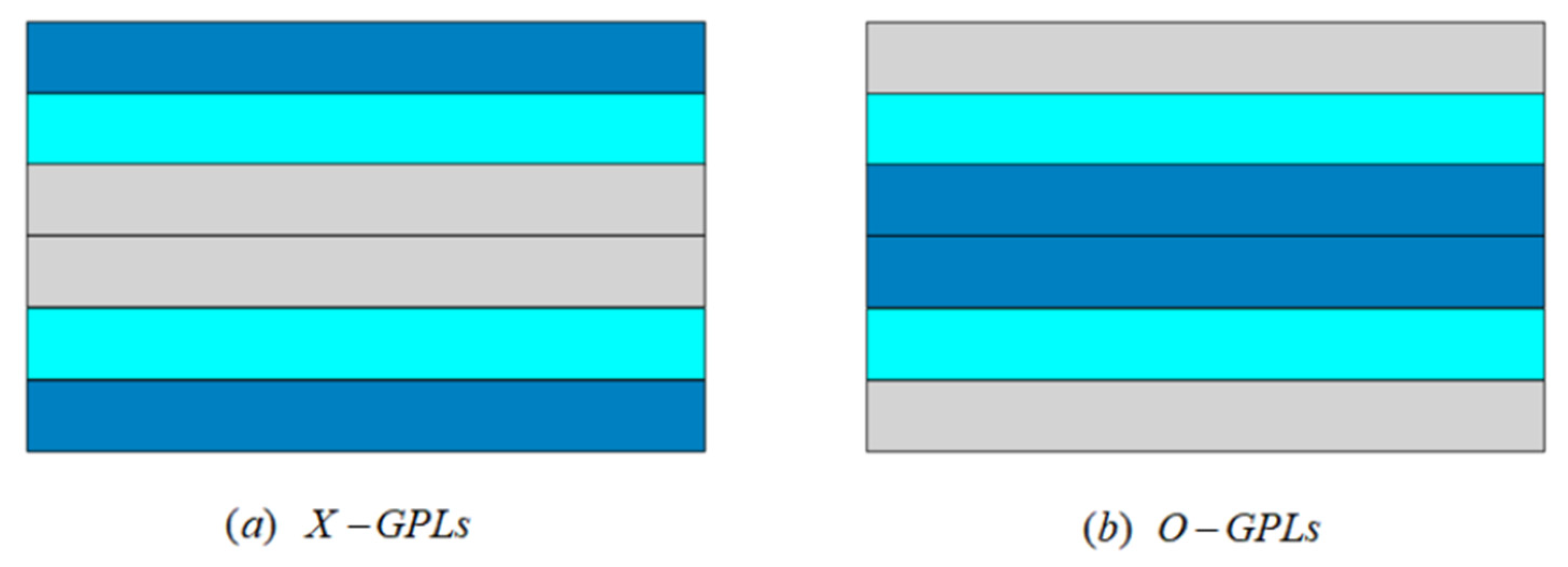
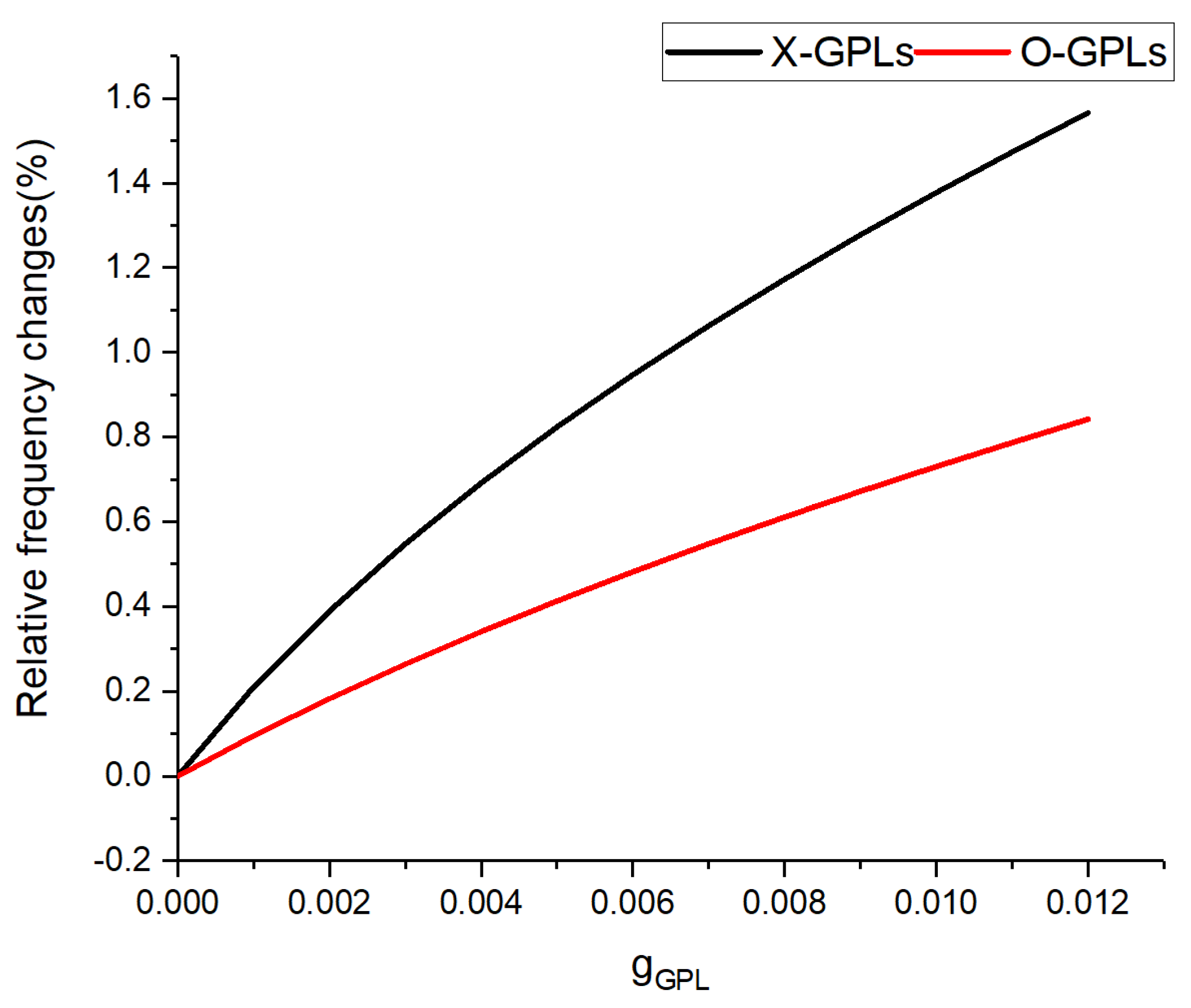
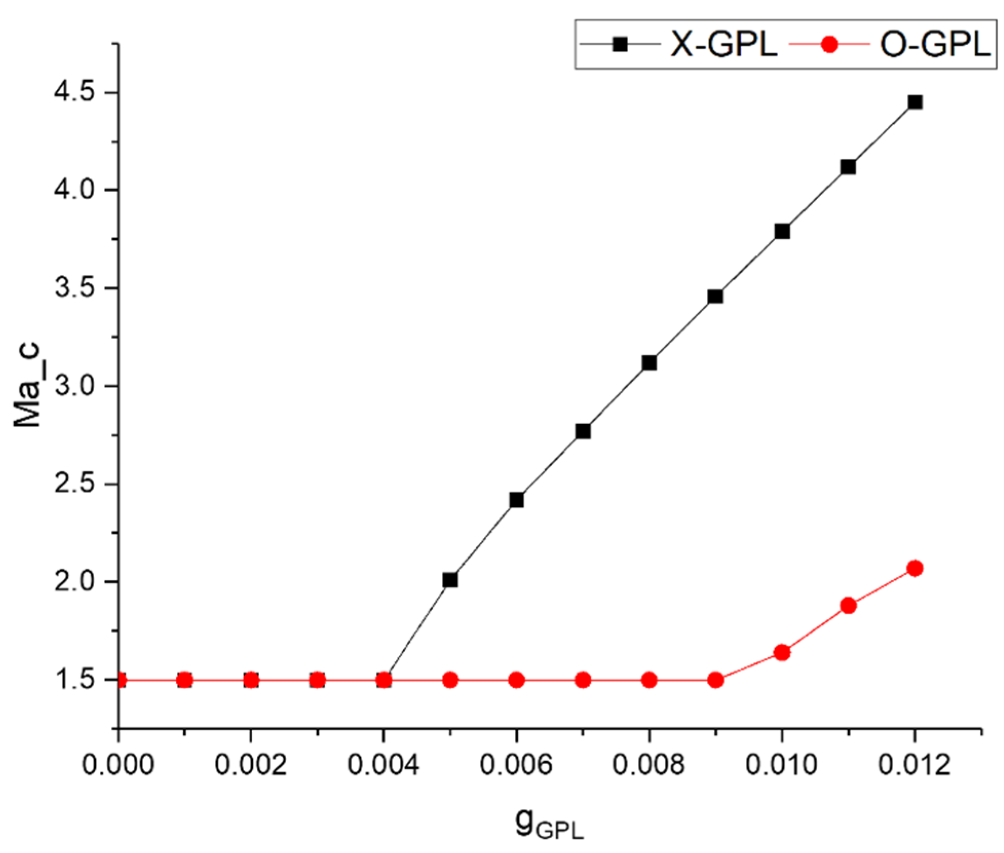
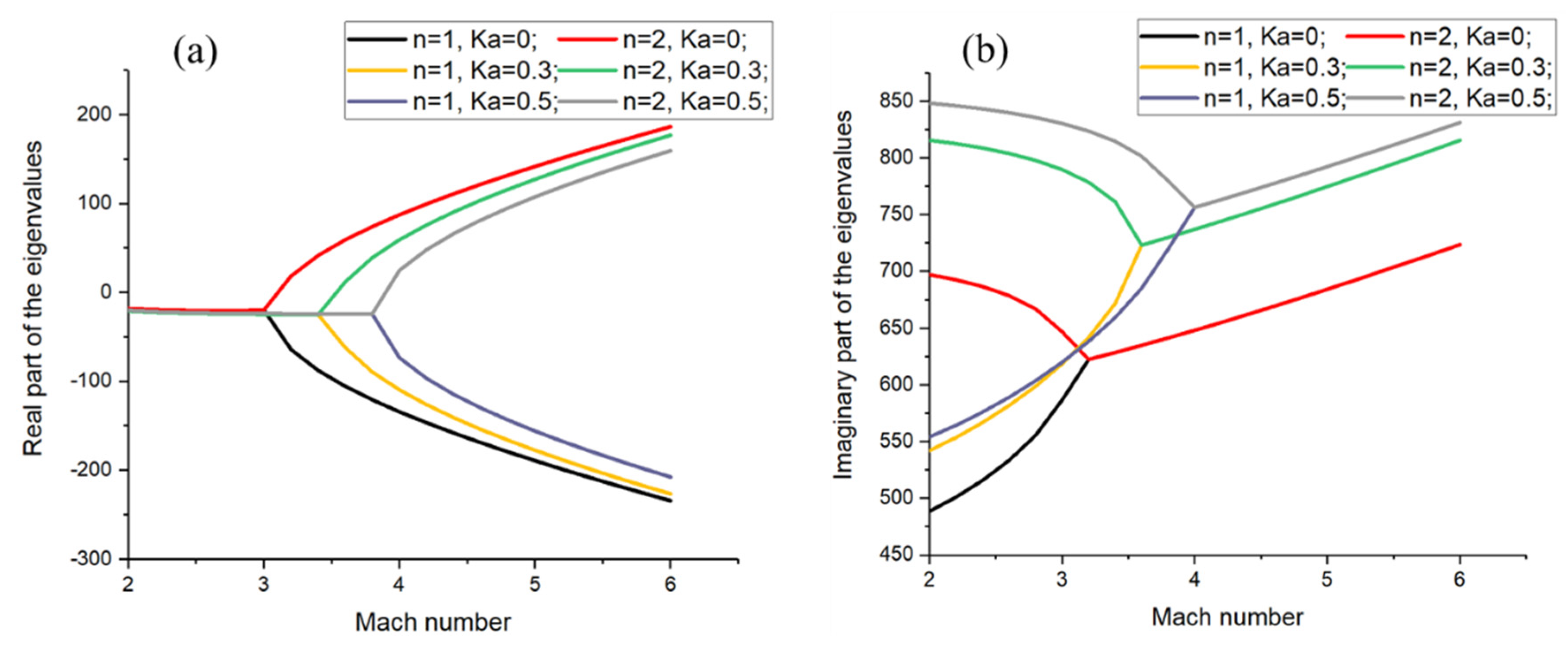
Adding a small content of GPLs nanofillers can raise the critical flutter Mach number. The reinforced effect of X-GPLs distribution is better than O-GPLs distribution.
(2)
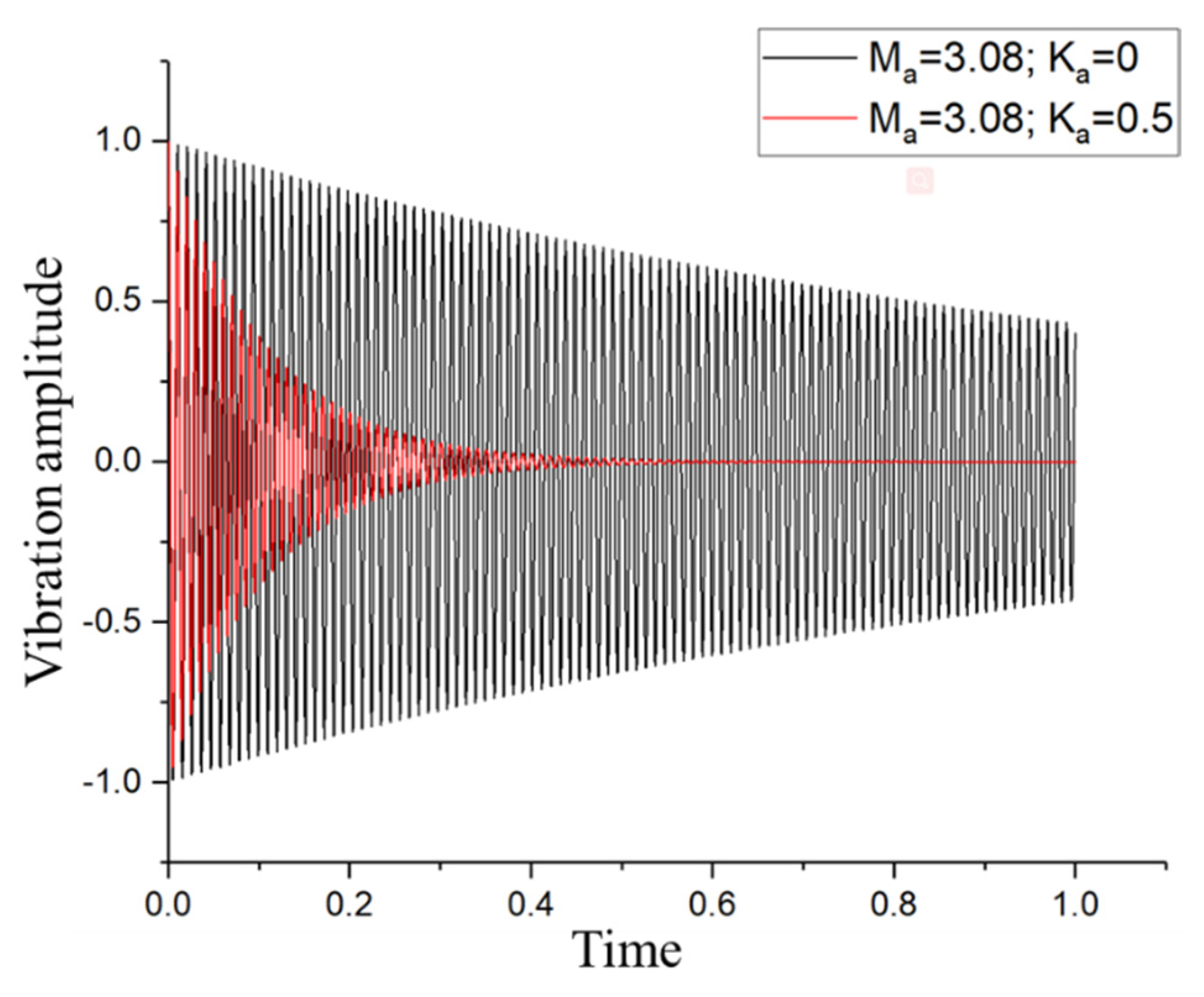
The displacement and acceleration feedback control can enhance the aeroelastic flutter characteristics of GPLs reinforced composite plate by attaching active stiffness and active mass.
(3)
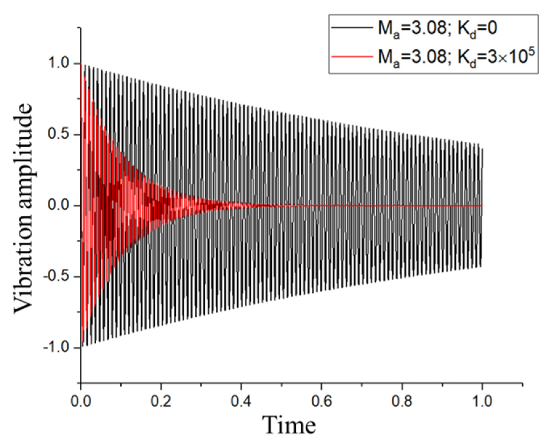
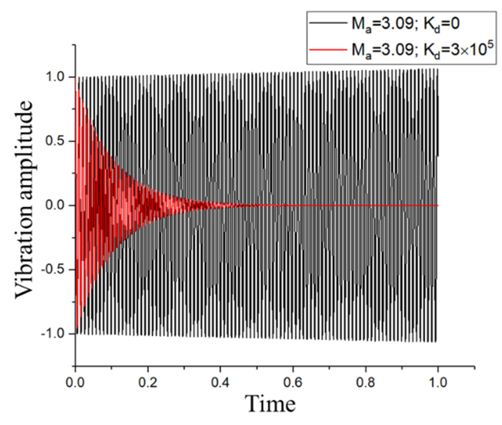
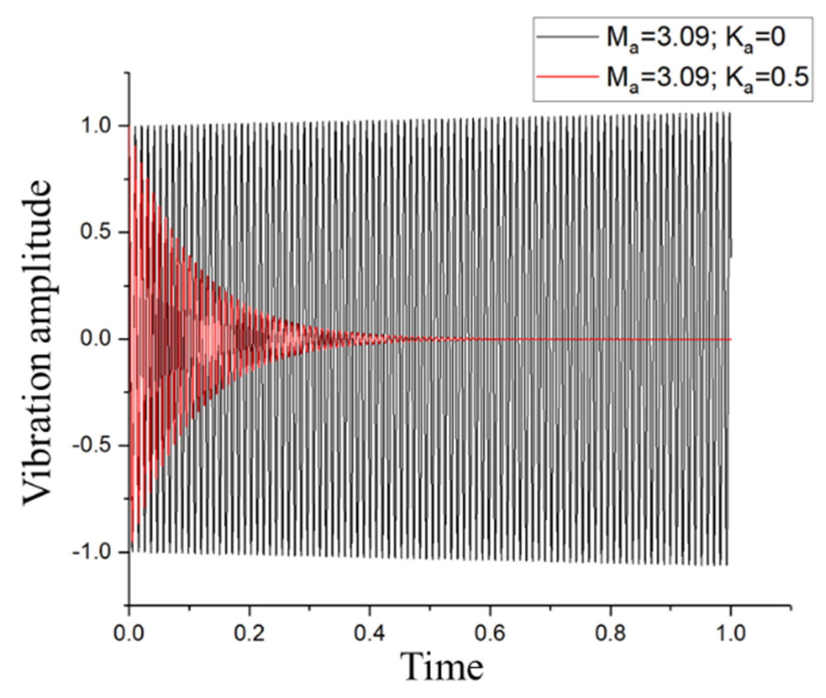
The displacement and acceleration feedback control can cause the vibration response to reduce faster before the critical flutter point. The displacement and acceleration feedback control can effectively suppress the occurrence of flutter at the critical flutter point.
(4)
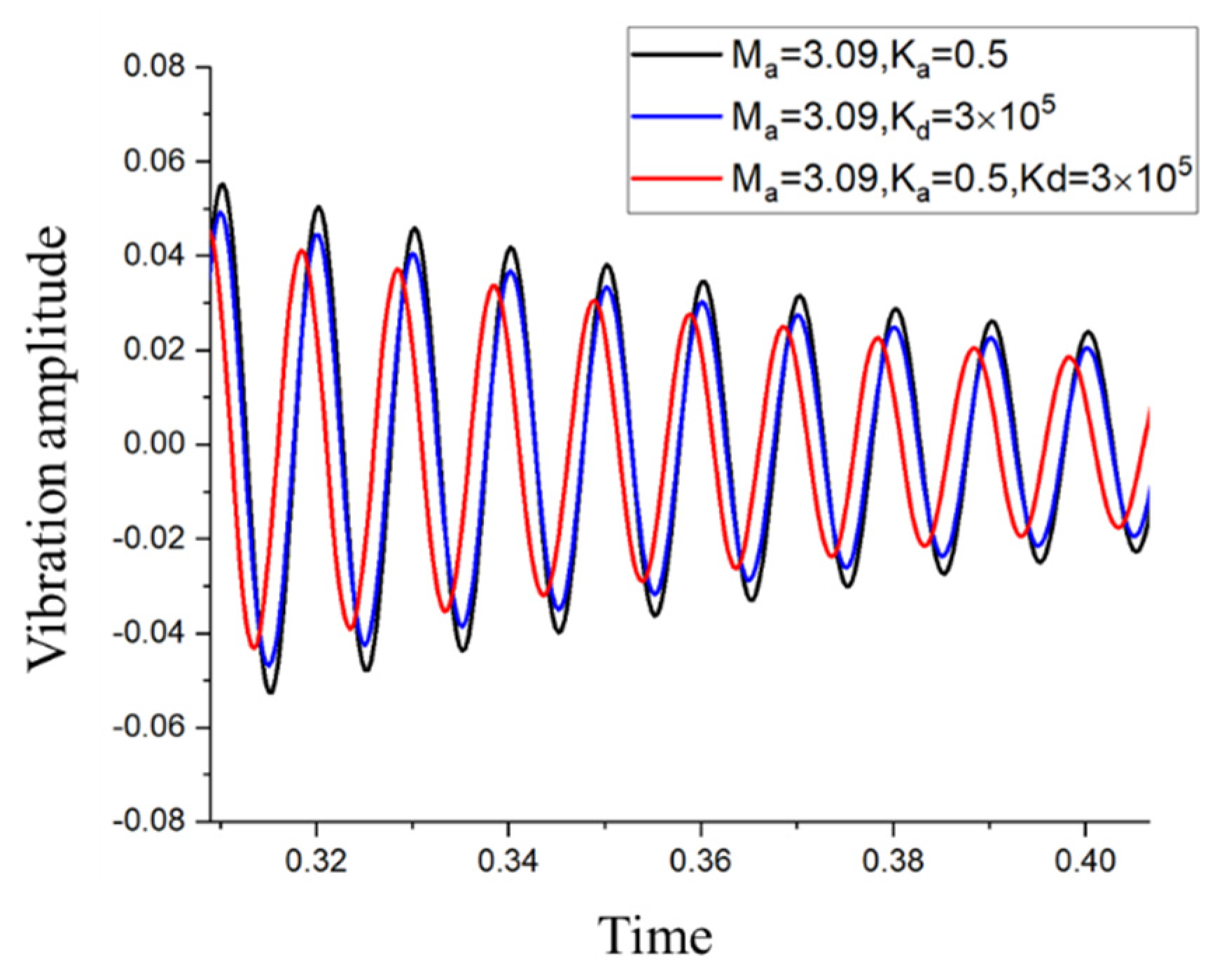
The combined control effect of active stiffness K p and active mass M p is better than considering only one of them.

Author Contributions

Conceptualization, J.C. and W.Z.; methodology, R.H. and D.L.; software, R.H. and D.L.; validation, J.C. and R.H.; formal analysis, D.L. and W.Z.; investigation, J.C. and R.H.; resources, J.C. and W.Z.; data curation, J.C. and R.H.; writing—original draft, R.H.; writing—review and editing, J.C. and D.L.; visualization, R.H.; supervision, W.Z.; project administration, J.C.; funding acquisition. J.C. All authors have read and agreed to the published version of the manuscript.

Funding

This research was funded by the Fundamental Research Program of Shenzhen Municipality, grant number JCYJ20170818094653701, the General Program of Science and Technology Development Project of Beijing Municipal Education Commission, grant number KM202110005030, and the National Natural Science Foundation of China (NNSFC), grant number 12102015.

Conflicts of Interest

The authors declare no conflict of interest.

Appendix A

The matrices in Equation (17) are written as
D c = i = 1 n i i + 1 E c i z 2 1 υ c 2 d z
M = 1 2 ρ c h 0 a 0 b W W T d x d y + 1 2 ρ p h p y 1 y 2 x 1 x 2 W W T d x d y
K 1 = D c 0 a 0 b ( 2 W T x 2 2 W T x 2 + υ c 2 W x 2 2 W T y 2 + 2 W y 2 2 W T y 2 + υ c 2 W y 2 2 W T x 2 ) d x d y + c 11 3 [ ( h 2 + h p ) 3 ( h 2 ) 3 ] x 1 x 2 y 1 y 2 2 W x 2 2 W T x 2 + 2 W y 2 2 W T y 2 d x d y + c 12 3 [ ( h 2 + h p ) 3 ( h 2 ) 3 ] x 1 x 2 y 1 y 2 2 W x 2 2 W T y 2 + 2 W y 2 2 W T x 2 d x d y + 4 c 66 3 [ ( h 2 + h p ) 3 ( h 2 ) 3 ] x 1 x 2 y 1 y 2 2 W x y 2 W T x y d x d y + G h 3 3 0 a 0 b 2 W x y 2 W T x y d x d y +
K 2 =   e 31 2 h p [ ( h 2 + h p ) 2 ( h 2 ) 2 ] x 1 x 2 y 1 y 2 2 W T 2 x 2 + 2 W T 2 y 2 d x d y
Κ 3 = 33 h p ( x 1 x 2 ) ( y 1 y 2 )
F q = 0 a 0 b W T d x d y δ r           F Δ p 1 = 0 a 0 b ζ W x W T d x d y           F Δ p 2 = 0 a 0 b μ W W T d x d y

References

  1. Prakash, T.; Ganapathi, M. Supersonic flutter characteristics of functionally graded flat panels including thermal effects. Compos. Struct. 2006, 72, 10–18. [Google Scholar] [CrossRef]
  2. Shin, W.H.; Oh, I.K.; Han, J.H.; Lee, I. Aeroelastic characteristics of cylindrical hybrid composite panels with viscoelastic damping treatments. J. Sound Vib. 2006, 296, 99–116. [Google Scholar] [CrossRef]
  3. Shin, W.H.; Oh, I.K.; Lee, I. Nonlinear flutter of aerothermally buckled composite shells with damping treatments. J. Sound Vib. 2009, 324, 556–569. [Google Scholar] [CrossRef]
  4. Chen, J.; Li, Q.S. Analysis of flutter and nonlinear dynamics of a composite laminated plate. Int. J. Struct. Stab. Dyn. 2016, 16, 1550019. [Google Scholar] [CrossRef]
  5. Chen, J.; Li, Q.S. Nonlinear aeroelastic flutter and dynamic response of composite laminated cylindrical shell in supersonic air flow. Compos. Struct. 2017, 168, 474–484. [Google Scholar] [CrossRef]
  6. Yang, X.D.; Yu, T.J.; Zhang, W.; Qian, Y.J.; Yao, M.H. Damping effect on supersonic panel flutter of composite plate with viscoelastic mid-layer. Compos. Struct. 2016, 137, 105–113. [Google Scholar] [CrossRef]
  7. Singha, M.K.; Mandal, M. Supersonic flutter characteristics of composite cylindrical panels. Compos. Struct. 2008, 82, 295–301. [Google Scholar] [CrossRef]
  8. Lin, H.G.; Shao, C.H.; Cao, D.Q. Nonlinear flutter and random response of composite panel embedded in shape memory alloy in thermal-aero-acoustic coupled field. Aerosp. Sci. Technol. 2020, 100, 105785. [Google Scholar] [CrossRef]
  9. Ferrari, G.; Amabili, M. Active vibration control of a sandwich plate by non-collocated positive position feedback. J. Sound Vib. 2015, 342, 44–56. [Google Scholar] [CrossRef]
  10. Zippo, A.; Ferrari, G.; Amabili, M.; Barbieri, M.; Pellicano, F. Active vibration control of a composite sandwich plate. Compos. Struct. 2015, 128, 100–114. [Google Scholar] [CrossRef]
  11. Lee, Y.S.; Vakakis, A.F.; Bergman, L.A.; McFarland, D.M.; Kerschen, G. Suppressing aeroelastic instability using broadband passive targeted energy transfers, Part 1: Theory. AIAA J. 2007, 45, 693–711. [Google Scholar] [CrossRef]
  12. Lee, Y.S.; Kerschen, G.; McFarland, D.M.; Hill, W.J.; Nichkawde, C.; Strganac, T.W.; Bergman, L.A.; Vakakis, A.F. Suppressing aeroelastic instability using broadband passive targeted energy transfers, part 2: Experiments. AIAA J. 2007, 45, 2391–2400. [Google Scholar] [CrossRef]
  13. Reddy, K.K.; Chen, J.; Behal, A.; Marzocca, P. Multi-input/multi-output adaptive output feedback control design for aeroelastic vibration suppression. J. Guid. Control Dyn. 2007, 30, 1040–1048. [Google Scholar] [CrossRef]
  14. Lu, S.F.; Jiang, Y.; Zhang, W.; Song, X.J. Vibration suppression of cantilevered piezoelectric laminated composite rectangular plate subjected to aerodynamic force in hygrothermal environment. Eur. J. Mech. Solids 2020, 83, 104002. [Google Scholar] [CrossRef]
  15. Na, S.; Librescu, L.; Kim, M.H.; Jeong, I.; Marzocca, P. Robust aeroelastic control of flapped wing systems using a sliding mode observer. Aerosp. Sci. Technol. 2006, 10, 120–126. [Google Scholar] [CrossRef]
  16. Na, S.S.; Librescu, L.; Marzocca, P.; Yoon, G.C.; Rubillo, C.; Bong, K. Robust aeroelastic control of two-dimensional supersonic flapped wing systems. Acta Mech. 2007, 192, 37–47. [Google Scholar] [CrossRef]
  17. Oveisi, A.; Nestorovic, T. Transient response of an active nonlinear sandwich piezolaminated plate. Commun. Nonlinear Sci. Numer. Simul. 2017, 45, 158–175. [Google Scholar] [CrossRef]
  18. Kasem, M.M.; Dowell, E.H. A study of the natural modes of vibration and aeroelastic stability of a plate with a piezoelectric material. Smart Mater. Struct. 2018, 27, 075043. [Google Scholar] [CrossRef]
  19. Li, F.M.; Chen, Z.B.; Cao, D.Q. Improving the aeroelastic flutter characteristics of supersonic beams using piezoelectric material. J. Intell. Mater. Syst. Struct. 2011, 22, 615–629. [Google Scholar] [CrossRef]
  20. Li, F.M.; Kishimoto, K.; Wang, Y.S.; Chen, Z.B.; Huang, A.H. Vibration control of beams with active constrained layer damping. Smart Mater. Struct. 2008, 17, 065036. [Google Scholar] [CrossRef]
  21. Li, F.M. Active aeroelastic flutter suppression of a supersonic plate with piezoelectric material. Int. J. Eng. Sci. 2012, 51, 190–203. [Google Scholar] [CrossRef]
  22. Song, Z.G.; Li, F.M.; Carrera, E.; Hagedorn, P. A new method of smart and optimal flutter control for composite laminated panels in supersonic airflow under thermal effects. J. Sound Vib. 2018, 414, 218–232. [Google Scholar] [CrossRef]
  23. Oh, I.K.; Lee, I. Supersonic flutter suppression of piezolaminated cylindrical panels based on multifield layerwise theory. J. Sound Vib. 2006, 291, 1186–1201. [Google Scholar] [CrossRef]
  24. Xue, Y.; Li, J.Q.; Li, F.M.; Song, Z.G. Active control of plates made of functionally graded piezoelectric material subjected to thermo-electro-mechanical loads. Int. J. Struct. Stab. Dyn. 2019, 19, 1950107. [Google Scholar] [CrossRef]
  25. Moon, S.H.; Hwang, J.S. Panel flutter suppression with an optimal controller based on the nonlinear model using piezoelectric materials. Compos. Struct. 2005, 68, 371–379. [Google Scholar] [CrossRef]
  26. Otiefy, R.A.H.; Negm, H.M. Wing box transonic-flutter suppression using piezoelectric self-sensing actuators attached to skin. Smart Mater. Struct. 2010, 19, 125001. [Google Scholar] [CrossRef]
  27. Potts, J.R.; Dreyer, D.R.; Bielawski, C.W.; Ruoff, R.S. Graphene-based polymer nanocomposites. Polymer 2011, 52, 5–25. [Google Scholar] [CrossRef] [Green Version]
  28. Rafiee, M.A.; Rafiee, J.; Yu, Z.Z.; Koratkar, N. Buckling resistant graphene nanocomposites. Appl. Phys. Lett. 2009, 95, 223103. [Google Scholar] [CrossRef]
  29. Rafiee, M.A.; Rafiee, J.; Wang, Z.; Song, H.H.; Yu, Z.Z.; Koratkar, N. Enhanced mechanical properties of nanocomposites at low graphene content. ACS Nano 2009, 3, 3884–3890. [Google Scholar] [CrossRef] [PubMed]
  30. Rafiee, M.A.; Rafiee, J.; Srivastava, I.; Wang, Z.; Song, H.H.; Yu, Z.Z.; Koratkar, N. Fracture and fatigue in graphene nanocomposites. Small 2010, 6, 179–183. [Google Scholar] [CrossRef] [PubMed]
  31. Montazeri, A.; Rafii-Tabar, H. Multiscale modeling of graphene- and nanotube-based reinforced polymer nanocomposites. Phys. Lett. A 2011, 375, 4034–4040. [Google Scholar] [CrossRef]
  32. Mortazavi, B.; Benzerara, O.; Meyer, H.; Bardon, J.; Ahzi, S. Combined molecular dynamics-finite element multiscale modeling of thermal conduction in graphene epoxy nanocomposites. Carbon 2013, 60, 356–365. [Google Scholar] [CrossRef]
  33. Wang, Y.; Yu, J.H.; Dai, W.; Song, Y.Z.; Wang, D.; Zeng, L.M.; Jiang, N. Enhanced Thermal and Electrical Properties of Epoxy Composites Reinforced With Graphene Nanoplatelets. Polym. Compos. 2015, 36, 556–565. [Google Scholar] [CrossRef]
  34. Yang, J.; Wu, H.L.; Kitipornchai, S. Buckling and postbuckling of functionally graded multilayer graphene platelet-reinforced composite beams. Compos. Struct. 2017, 161, 111–118. [Google Scholar] [CrossRef] [Green Version]
  35. Wang, F.Z.; Drzal, L.T.; Qin, Y.; Huang, Z.X. Mechanical properties and thermal conductivity of graphene nanoplatelet/epoxy composites. J. Mater. Sci. 2015, 50, 1082–1093. [Google Scholar] [CrossRef]
  36. Song, M.T.; Yang, J.; Kitipornchai, S.; Zhu, W.D. Buckling and postbuckling of biaxially compressed functionally graded multilayer graphene nanoplatelet-reinforced polymer composite plates. Int. J. Mech. Sci. 2017, 131, 345–355. [Google Scholar] [CrossRef] [Green Version]
  37. Song, M.T.; Kitipornchai, S.; Yang, J. Free and forced vibrations of functionally graded polymer composite plates reinforced with graphene nanoplatelets. Compos. Struct. 2017, 159, 579–588. [Google Scholar] [CrossRef]
  38. Lin, H.G.; Cao, D.Q.; Xu, Y.Q. Vibration, buckling and aeroelastic analyses of functionally graded multilayer graphene-nanoplatelets-reinforced composite plates embedded in piezoelectric layers. Int. J. Appl. Mech. 2018, 10, 1850023. [Google Scholar] [CrossRef]
  39. Saidi, A.R.; Bahaadini, R.; Majidi-Mozafari, K. On vibration and stability analysis of porous plates reinforced by graphene platelets under aerodynamical loading. Compos. Part B-Eng. 2019, 164, 778–799. [Google Scholar] [CrossRef]
  40. Zhou, X.P.; Wang, Y.W.; Zhang, W. Vibration and flutter characteristics of GPL-reinforced functionally graded porous cylindrical panels subjected to supersonic flow. Acta Astronaut. 2021, 183, 89–100. [Google Scholar] [CrossRef]
  41. Kumar, K.R.; Narayanan, S. Active vibration control of beams with optimal placement of piezoelectric sensor/actuator pairs. Smart Mater. Struct. 2008, 17, 055008. [Google Scholar] [CrossRef]
  42. Kim, H.W.; Kim, J.H. Effect of piezoelectric damping layers on the dynamic stability of plate under a thrust. J. Sound Vib. 2005, 284, 597–612. [Google Scholar] [CrossRef]
  43. Koo, K.N.; Hwang, W.S. Effects of hysteretic and aerodynamic damping on supersonic panel flutter of composite plates. J. Sound Vib. 2004, 273, 569–583. [Google Scholar] [CrossRef]
  44. Kumar, P.; Srinivas, J. Vibration, buckling and bending behavior of functionally graded multi walled carbon nanotube reinforced polymer composite plates using the layer-wise formulation. Compos. Struct. 2017, 177, 158–170. [Google Scholar] [CrossRef]
  45. Liu, C.; Ye, Z.Y. Aerodynamic nonlinearity for surface vibration in supersonic flow. Acta Aerodyn. Sin. 2018, 36, 1027–1033. [Google Scholar]
Figure 1. The model of the functionally graded GPLs reinforced plate with a piezoelectric patch.
Applsci 12 01244 g001
Figure 2. Distribution pattern of GPLs: (a) X-GPLs, (b) O-GPLs.
Applsci 12 01244 g002
Figure 3. Effects of weight fraction on the frequency change for GPLs plates with different GPLs distribution patterns.
Applsci 12 01244 g003
Figure 4. Effect of weight fraction on the critical flutter Mach number of the GPLs plates with different distribution patterns.
Applsci 12 01244 g004
Figure 5. The eigenvalues of the system with the Mach number, (a) the real parts of the eigenvalues, (b) the imaginary parts of the eigenvalues.
Applsci 12 01244 g005
Figure 6. Responses of the GPLs plate under different Mach numbers before the critical flutter number.
Applsci 12 01244 g006
Figure 7. Response of the plate at the critical flutter number.
Applsci 12 01244 g007
Figure 8. The eigenvalues of the GPLs plate bond with a piezoelectric patch with respect to the Mach number under displacement feedback control ( K d = 0 ,   K d = 1.5 × 10 5 ,   K d = 3 × 10 5 ) , (a) the real parts of the eigenvalues; (b) the imaginary parts of the eigenvalues.
Applsci 12 01244 g008
Figure 9. The comparison of the response of the plate after introducing the displacement feedback gain K d before the critical flutter point.
Applsci 12 01244 g009
Figure 10. The comparison of the plate’s response after introducing the displacement feedback gain K d control at the critical flutter point.
Applsci 12 01244 g010
Figure 11. The eigenvalues of the GPLs plate bond with piezoelectric layer with the Mach number under the acceleration feedback control ( K a = 0 ,   K a = 0.3 ,   K a = 0.5 ) (a) the real parts of the eigenvalues; (b) the imaginary parts of the eigenvalues.
Applsci 12 01244 g011
Figure 12. The comparison of the response of the GPLs plate after introducing the acceleration feedback control before the critical flutter point for K a = 0.5 .
Applsci 12 01244 g012
Figure 13. The comparison of the response of the GPLs plate after introducing the acceleration feedback control at the critical flutter point for K a = 0.5 .
Applsci 12 01244 g013
Figure 14. The eigenvalues of the GPLs plate, varying the Mach number under the combination of displacement feedback control and acceleration feedback control ( K a = 0.5 ,       K d = 0 ;   K a = 0 ,       K d = 3 × 10 5 ;   K a = 0.5 ,       K d = 3 × 10 5 ) (a) the real parts of the eigenvalues; (b) the imaginary parts of the eigenvalues.
Applsci 12 01244 g014
Figure 15. The comparison of the response of the GPLs plate after introducing the combination of the displacement feedback control and acceleration feedback control.
Applsci 12 01244 g015
Table 1. Comparisons of the frequency parameters ω ¯ = ω h ρ M / E M of the simply supported GPLs reinforced composite plate with references [37,44].
PatternSource p ,   q
1,12,12,23,13,2
Epoxy polymerSong et al.0.05840.13910.21320.25950.3251
ANSYS0.05630.13610.20640.25690.3173
Present0.05870.14060.21640.26410.3321
X-GPLsSong et al.0.13780.32490.49390.59840.7454
ANSYS0.13190.30430.44240.56570.6475
Present0.13850.32890.50280.61120.7645
O-GPLsSong et al.0.1020.24560.37960.46450.586
ANSYS0.08810.21620.33360.41660.5658
Present0.10230.24720.38350.47020.5949
Note: p and q mean the number of axial half-wave and circumferential wave in the modal functions for a simply supported GPLs reinforced composite plate.
Publisher’s Note: MDPI stays neutral with regard to jurisdictional claims in published maps and institutional affiliations.

