
Bent and Branched Microstrip-Line Antennas for Circular Polarization


1
College of Engineering, Shibaura Institute of Technology, Tokyo 135-8548, Japan
2
Science and Engineering, Hosei University, Tokyo 184-8584, Japan
*
Author to whom correspondence should be addressed.
Appl. Sci. 2022, 12(3), 1711; https://0-doi-org.brum.beds.ac.uk/10.3390/app12031711
Submission received: 31 December 2021
/
Revised: 28 January 2022
/
Accepted: 1 February 2022
/
Published: 7 February 2022
(This article belongs to the Special Issue Advances in Analytical-Numerical Techniques for Planar Microwave Circuits and Microstrip Antennas)
Abstract
:We analyze three transmission-line antennas using the moment method. Each line antenna comprises a coplanar feed line, loops, and straight segments connecting the loops and feedline. First, we investigate bent and branched line antennas with loops on one side of the feedline. It is found that the segment length affects both the beam direction and axial ratio for the bent line antenna; in contrast, it only affects the branched line antenna’s axial ratio, resulting in a more straightforward design. Subsequently, the branched line antenna is modified with loops on both sides of the feedline to enhance the gain. It is observed that the antenna shows a gain enhancement of 2.0 dB, maintaining the same axial-ratio bandwidth as that of the original branched line antenna. The simulated results are validated by experimental work.
1. Introduction
There have been many studies on microstrip transmission-line antennas (line antennas) radiating a circularly polarized (CP) wave [1,2]. The line antenna is created by using the feedline itself that is periodically bent [3,4,5] or branched [6,7,8] above the ground plane. It has the advantage of a simple feed system for a series-fed linear array. So far, line antennas have been designed individually, and there have been few systematic studies on different line antennas [9].
This paper investigates different line antennas, where a loop shape [5] is selected as the feedline’s periodical bend for a systematic study. Loop-shape selection enables us to study bent and branched line antennas (see Figure 1b,c), together with a modified branched one (see Figure 1d). All line antennas are analyzed using the moment method [10].
The systematic study aids in designing and understanding a line antenna since the study discusses three different line-antennas having relationships and presents new findings. The relationships concern both configurations (see Figure 1b–d) and radiation characteristics (Figures 3, 5, and 9a). The new findings include the following:
Note that a finding of (1) has never been presented in the authors’ publications [3,4,7], including a preliminary conference paper [9]. Moreover, note that in [9], there has been no experimental result to validate a finding of (2). This paper is the only systematic study on three different line antennas to the best of the authors’ knowledge.
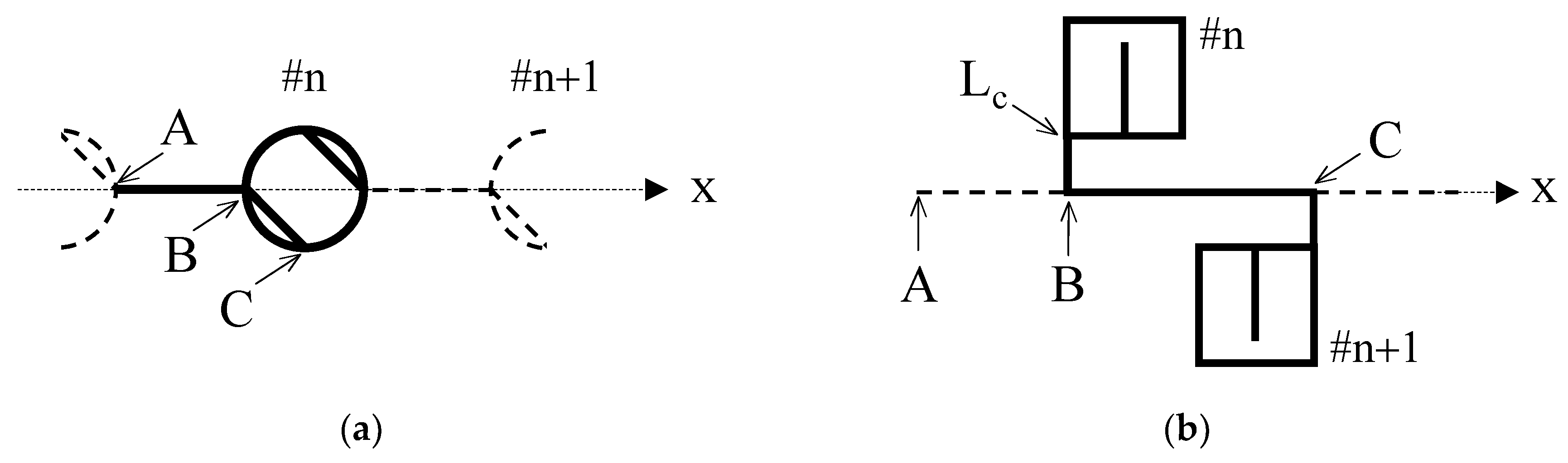
It should be emphasized that present elements (Figure 1b–d) are entirely different from the ones in the authors’ publications (see Figure 2a,b). In Figure 2a, a line A-B-C is bent inside the loop, while a line A-B-C is branched to a loop corner Lc (not the loop-side center) in Figure 2b. These traditional elements have never resulted in the systematic study of this paper. In other words, the present elements themselves constitute the novelty of this paper.
2. Bent Line Antenna
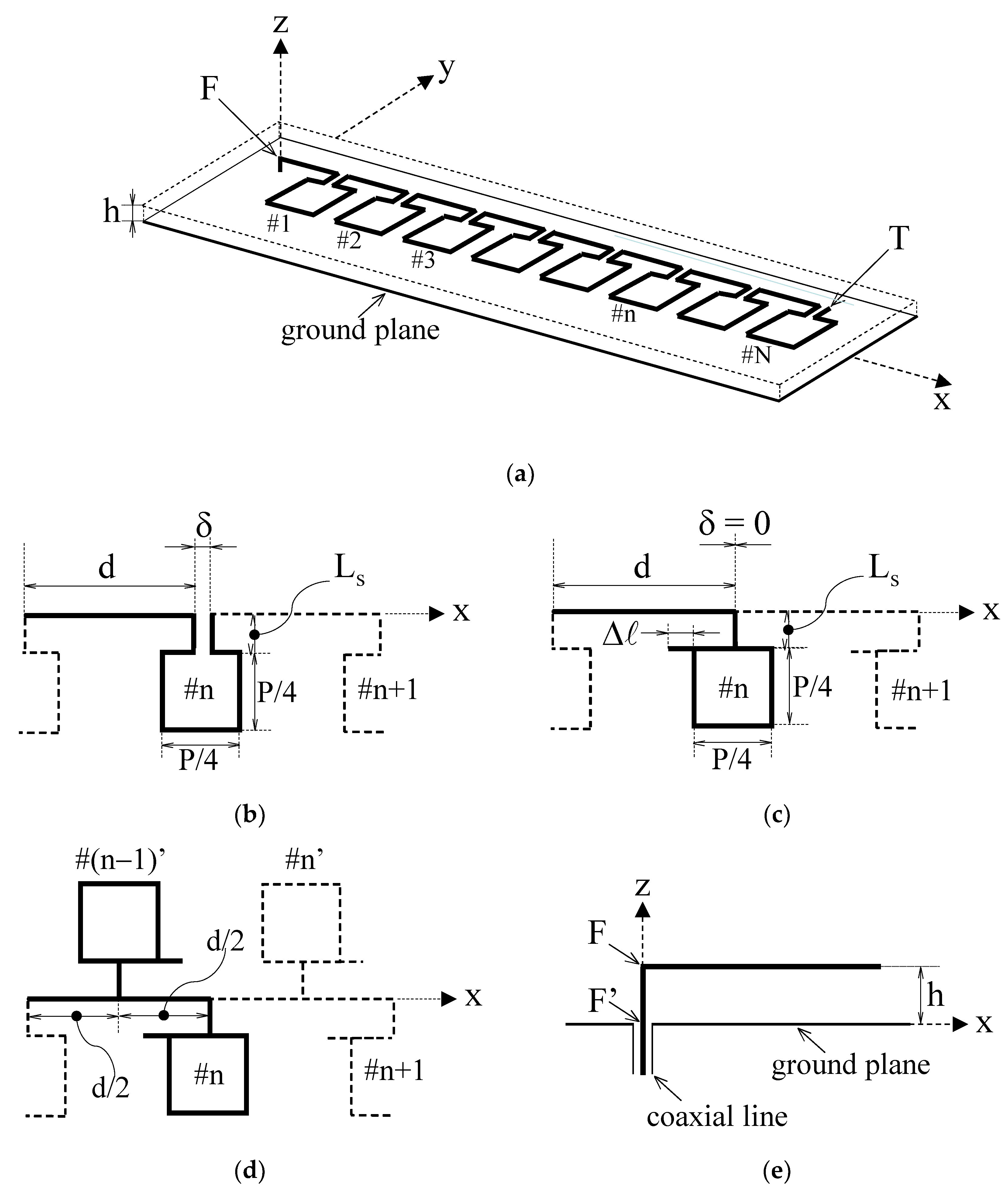
Figure 1a shows an antenna configuration. The antenna has N periodical bends in a feedline F-T located above the ground plane at height h. Each periodical bend consists of a line of length d, a square loop of perimeter P with a gap δ, and two segments of length Ls, as shown in Figure 1b. Feedline F-T is excited at the left terminal F via a vertical wire F-F’ using a coaxial line (see Figure 1e), and the right terminal T is open-circuited. A matched termination [1,2] is not used to avoid decreased radiation efficiency. The antenna is made of wires with a radius ρ [4,11].
It is known that a wire is regarded as a strip having the equivalent width of w = 4ρ [12]. Therefore, a wire analysis implies its equivalent strip one. In our analysis, the strip is located on an air-dielectric substrate to avoid decreased radiation efficiency [4]. An antenna printed on a conventional dielectric substrate may be designed based on the antenna on an air-dielectric substrate, i.e., by changing the configuration parameters in the free-space wavelength to those in the wavelength guided on the conventional dielectric substrate [2,4].
Using the moment method [10], we design the antenna to radiate a CP beam in a direction normal to the antenna plane in the +z-axis direction. For this, we chose the loop perimeter P and path length along the periodical bend (d + 2Ls + P − δ) to be 1λ0 and 2λ0, respectively, where λ0 is the free-space wavelength at a test frequency f0. The other configuration parameters are fixed to be (h, ρ) = (λ0/8, λ0/200) [9,11] throughout this paper. Note that the ground plane is assumed to be perfectly conducting and of infinite extent, and image theory [13] is used in the analysis. Moreover, note that the line length in a periodical bend of #1 is arbitrary (set to be d1 = λ0/8).
We use self-developed software, where wire radius ρ is assumed to be small compared with λ0 (ρ << λ0). This assumption ensures that the antenna characteristics can be calculated by only the current flowing in the wire axis direction. The current is expanded using piecewise sinusoidal functions. A segment length of approximately λ0/50 is used in the analysis.
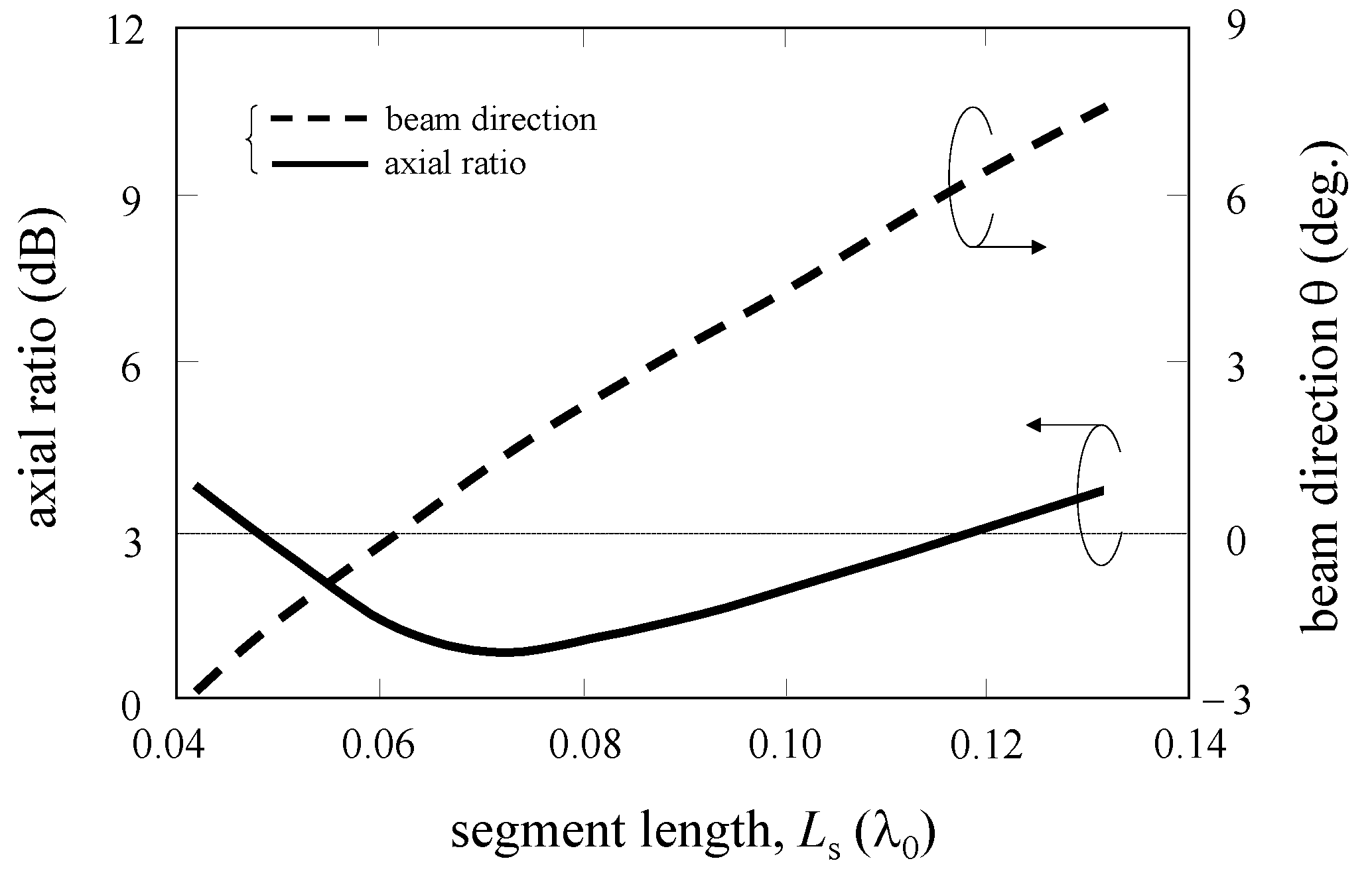
Calculations for N = 12 [4] show that one of the critical parameters for CP beam formation is segment length Ls. The simulated beam direction and axial ratio versus Ls are shown in Figure 3, where the other parameters are (d, P, δ) = (0.96λ0, 1.12λ0, 0.06λ0). It is observed that the beam direction becomes θ = 0° for Ls = 0.06λ0, together with an axial ratio of less than 3 dB. Note that Ls affects both the beam direction and axial ratio.
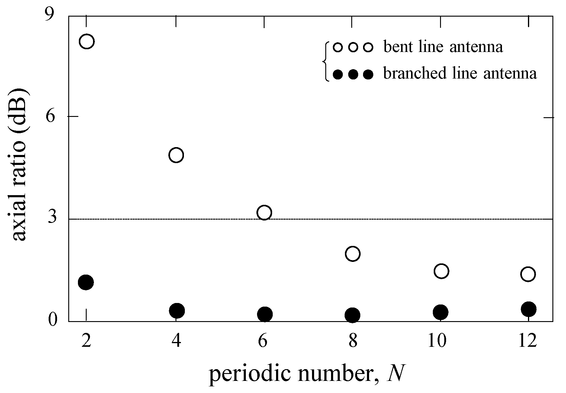
Since the antenna feedline F-T has open-circuited termination T, there should be a minimum number of periodical bends for CP radiation. This is shown with small circles in Figure 4. The axial ratio for Ls = 0.06λ0 is evaluated as a function of N with the other parameters being fixed. It is found that the antenna radiates a CP wave with an axial ratio of less than 3 dB for N > 6.
The increased axial ratios for a few periodical bends are due to increased current reflected from the terminal T [14]. The reflected current gives rise to the opposite rotational sense of CP radiation to that of traveling current, deteriorating the axial ratio. In the next section, we investigate a line antenna that travels and reflects currents that contribute to the same rotational sense of CP radiation.
3. Branched Line Antenna
We design two antennas: one has loops on one side of the feedline, and the other has additional loops on the other side to increase gain.
3.1. Original Antenna
Figure 1c shows an antenna configuration. We create the antenna using the bent line antenna in Section 2: Each loop gap is chosen to be δ = 0 (the two segments of length Ls are replaced with a single one), and a stub of length Δℓ is added to each loop [11]. The antenna is again designed for a CP beam in the +z-axis direction.
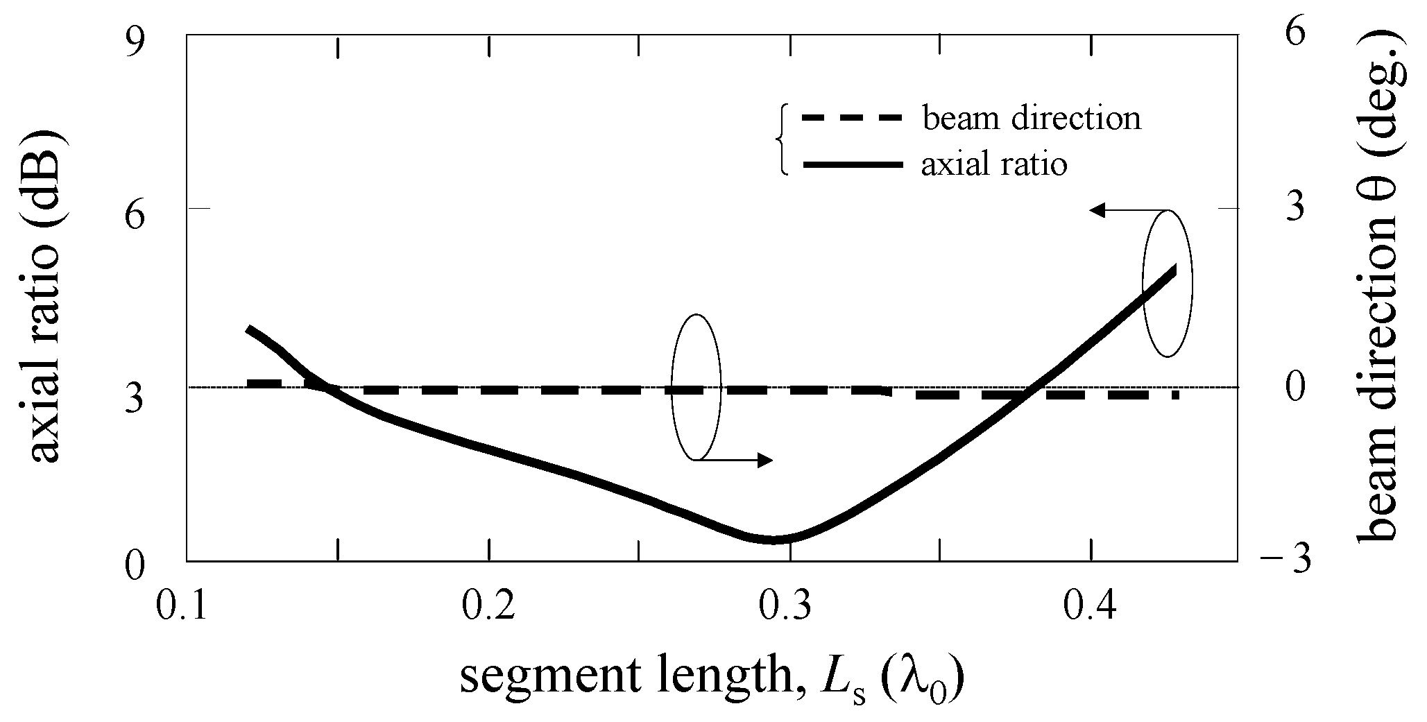
Figure 5 shows the simulated beam direction and axial ratio versus Ls for N = 12 and (d, P, Δℓ) = (1.00λ0, 0.90λ0, 0.12λ0). It should be noted that beam direction remains unchanged at θ = 0° regardless of the variation in Ls. It is also found that the minimum axial ratio is obtained at Ls = 0.30λ0. These two facts make the antenna design more straightforward when compared with that in Section 2 (see Figure 3).
We calculate the axial ratio versus periodic number N, as in Section 2. The result is shown with dots in Figure 4. It is emphasized that the axial ratio is almost constant even when the periodic number becomes small, e.g., N = 4.
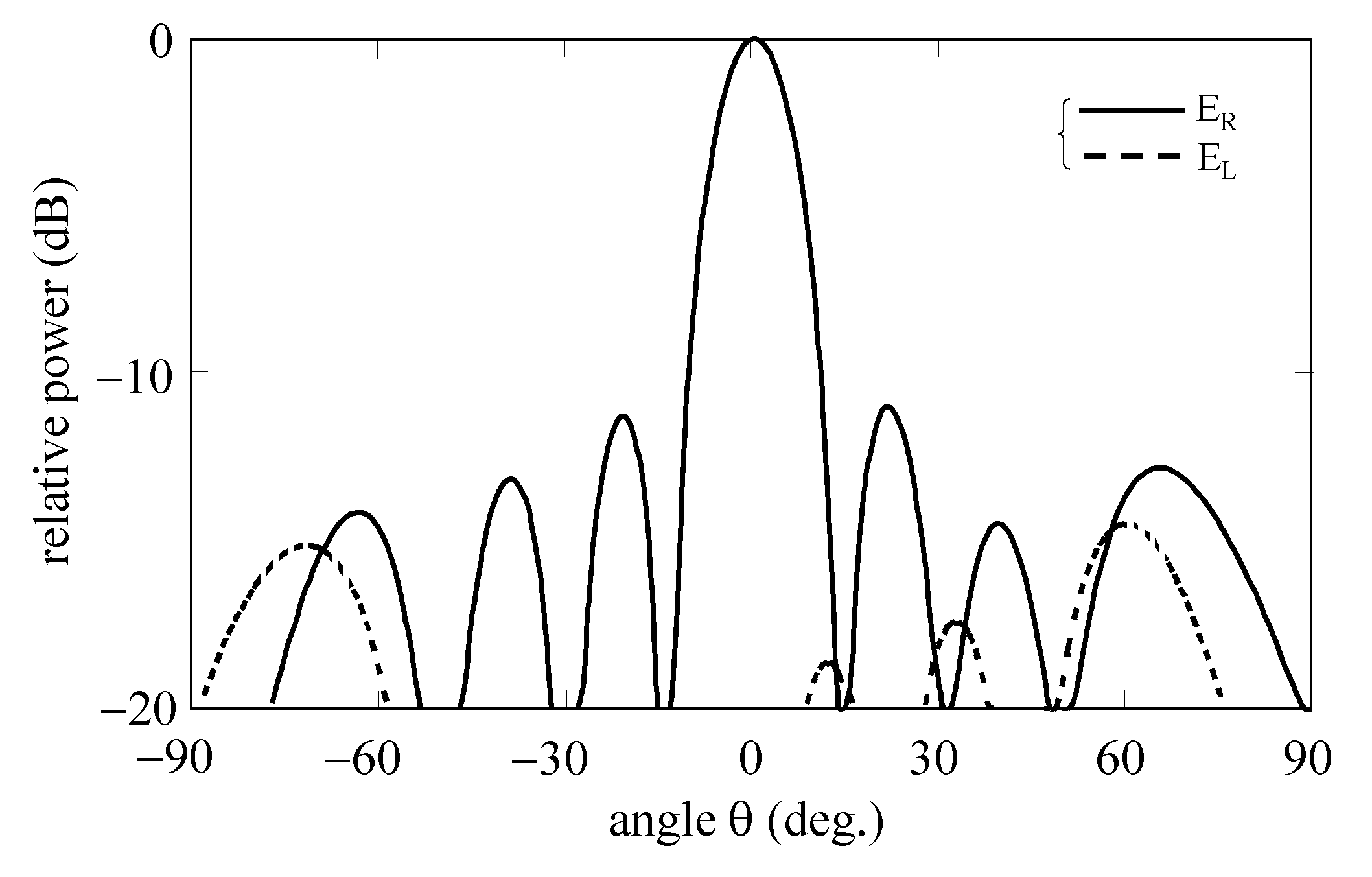
The simulated radiation pattern for N = 4 is shown in Figure 6. Radiation decomposed into right (ER) and left-hand (EL) CP wave components, which are shown with solid and dotted lines, respectively. It is observed that the antenna radiates a CP beam in the +z-axis direction. The half-power beamwidth (HPBW) and gain are 13° and 14.6 dBi, respectively. In order to increase the gain, we modify the antenna in the next section.
3.2. Modified Antenna
Figure 1d shows an antenna configuration. The antenna is created using the branched line antenna in Section 3.1: We add N−1 loops and segments on feedline F-T’s other side (the +y side). Each additional segment is connected to the line center of length d (=1λ0). For CP beam formation in the +z-axis direction, each additional loop #n’ is rotated by 180° concerning the original loop #n to compensate for an excitation phase difference of 180° (= d/2 × 360°/λ0). The other configuration parameters are the same as those of the original antenna with N = 4, resulting in 7 (=N + N − 1) loops and segments.
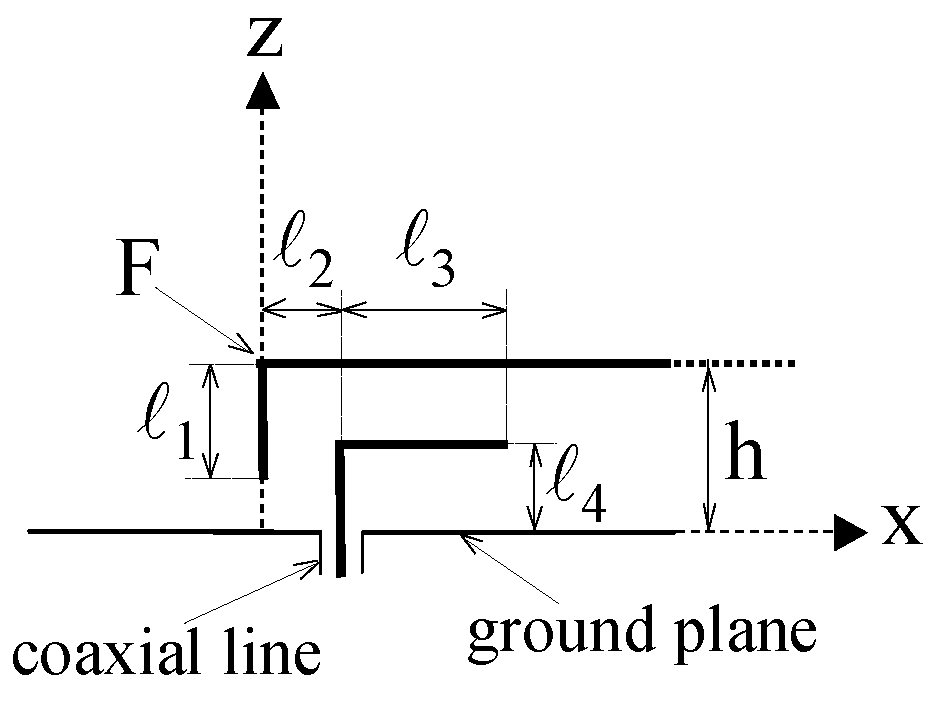
First, the antenna is analyzed for a direct feed using vertical wire F-F′ shown in Figure 1e. After confirming CP beam formation, we replace the direct feed with an electromagnetic-coupling one shown in Figure 7 to obtain impedance matching. The feed parameters are selected so that they do not deteriorate the radiation characteristics for the direct feed and are determined to be (ℓ1, ℓ2, ℓ3, ℓ4) = (0.08λ0, 0.02λ0, 0.18λ0, 0.08λ0).
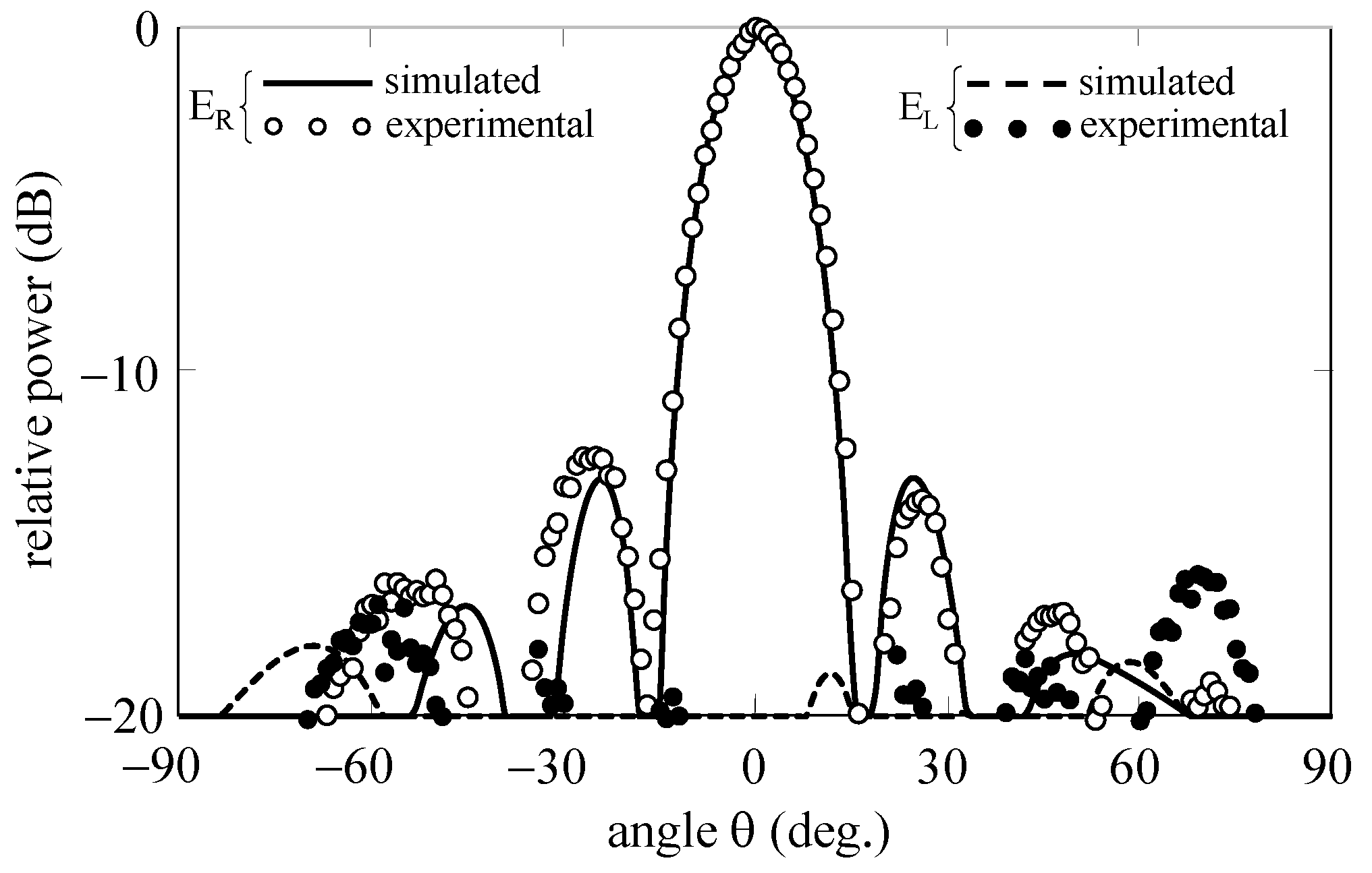
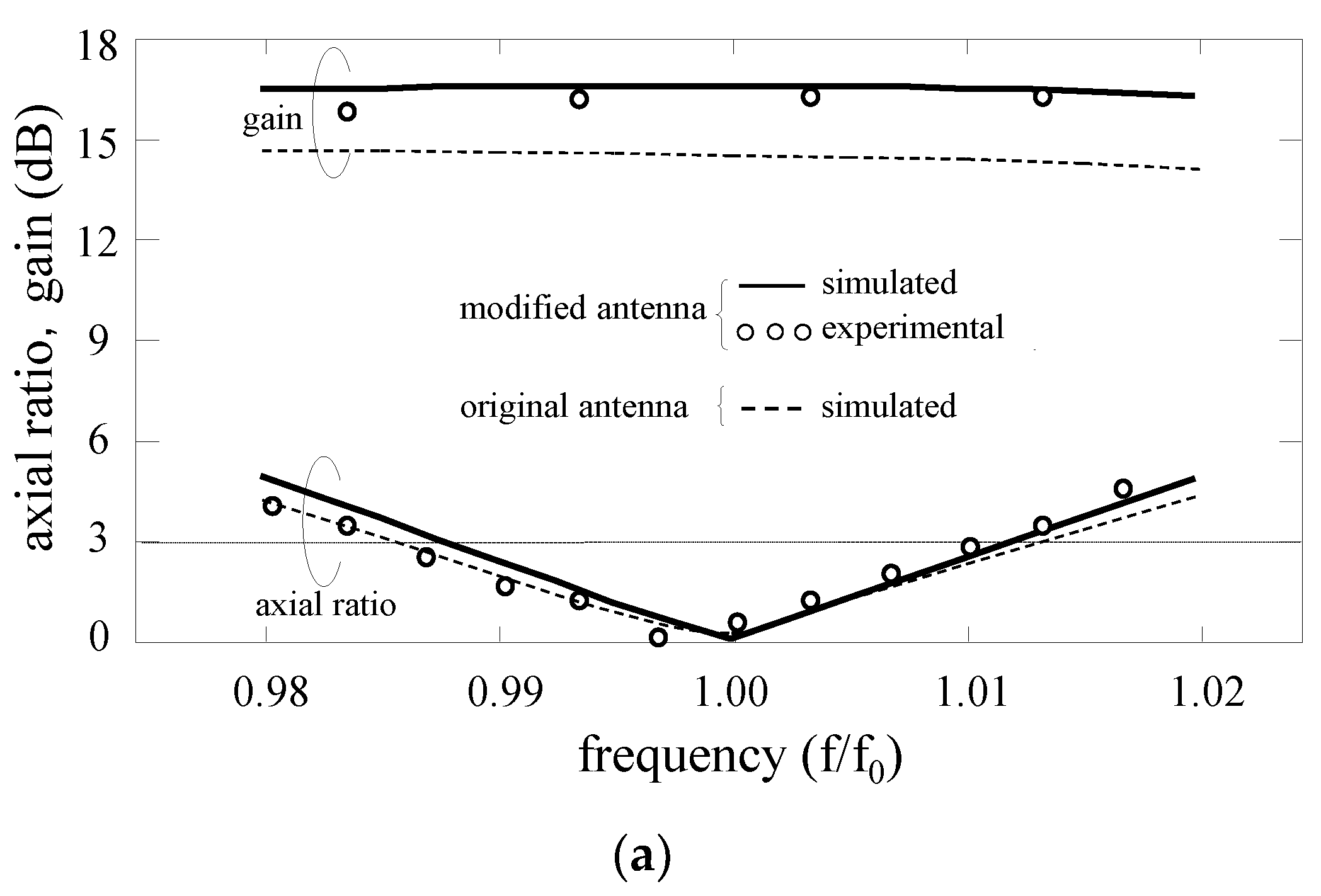
The simulated radiation pattern is shown with solid and dotted lines in Figure 8. It is observed that the antenna radiates a CP beam in the +z-axis direction. The HPBW is 12°, and the gain is evaluated to be 16.6 dBi. It is emphasized that the gain is increased by 2.0 dB compared with that of the original antenna.
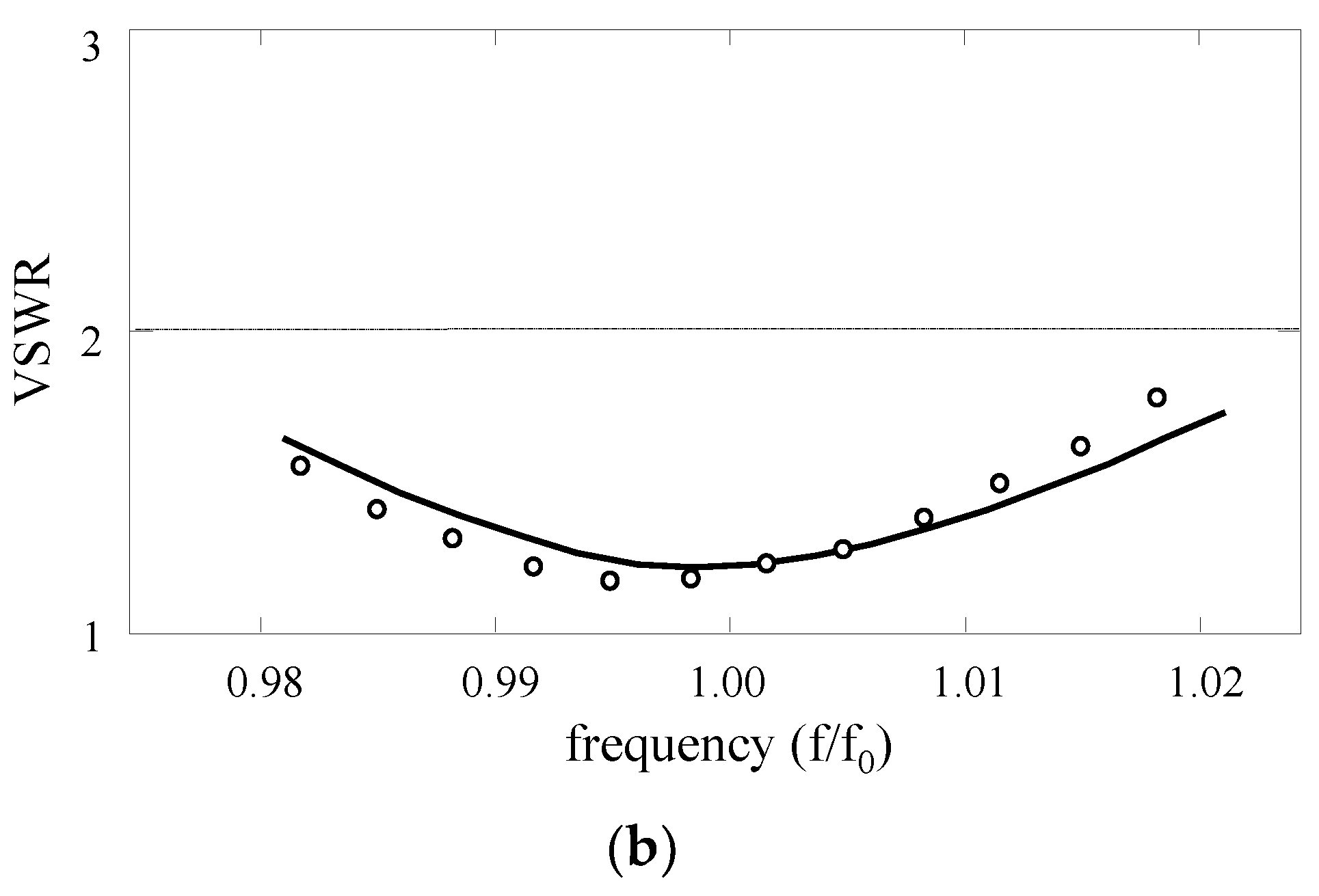
Solid lines in Figure 9 show the simulated frequency responses of the gain, axial ratio, and VSWR. It is found that a CP wave bandwidth for a 3 dB axial-ratio criterion is 2.5%, where the gain is almost constant with a VSWR of less than 2. For reference, the gain and axial ratio of the original antenna are also shown with dotted lines. The CP wave bandwidth is almost the same as that of the modified antenna. It can be said that the modified antenna has a gain enhancement of 2.0 dB without deterioration in the CP wave bandwidth of the original antenna.
The increased gain is explained using the radiation mechanism of a line antenna with loops [2,5]. Let us focus on a periodical bend of #n shown in Figure 1b. Radiation from the periodical bend is decomposed into partial radiation from the loop part and partial radiation from parts other than the loop. It is known that partial radiation from the loop part becomes dominant in the broadside (z-axis) direction for a loop perimeter of 1λ0. This radiation mechanism holds for other periodical branches of #n shown in Figure 1c,d. Note that partial radiation from the loop part is CP due to a traveling-wave current along the loop.
Keeping the abovementioned radiation mechanism in mind, we consider the gains of modified and original branched line antennas. Remember that each antenna is designed for a broadside beam, where the phase of partial radiation from each loop part is the same. This means that the gain depends on the number of loops. The modified antenna has more loops than the original one, resulting in a larger gain. In summary, the increased gain of the modified antenna is due to more loops than the original one.
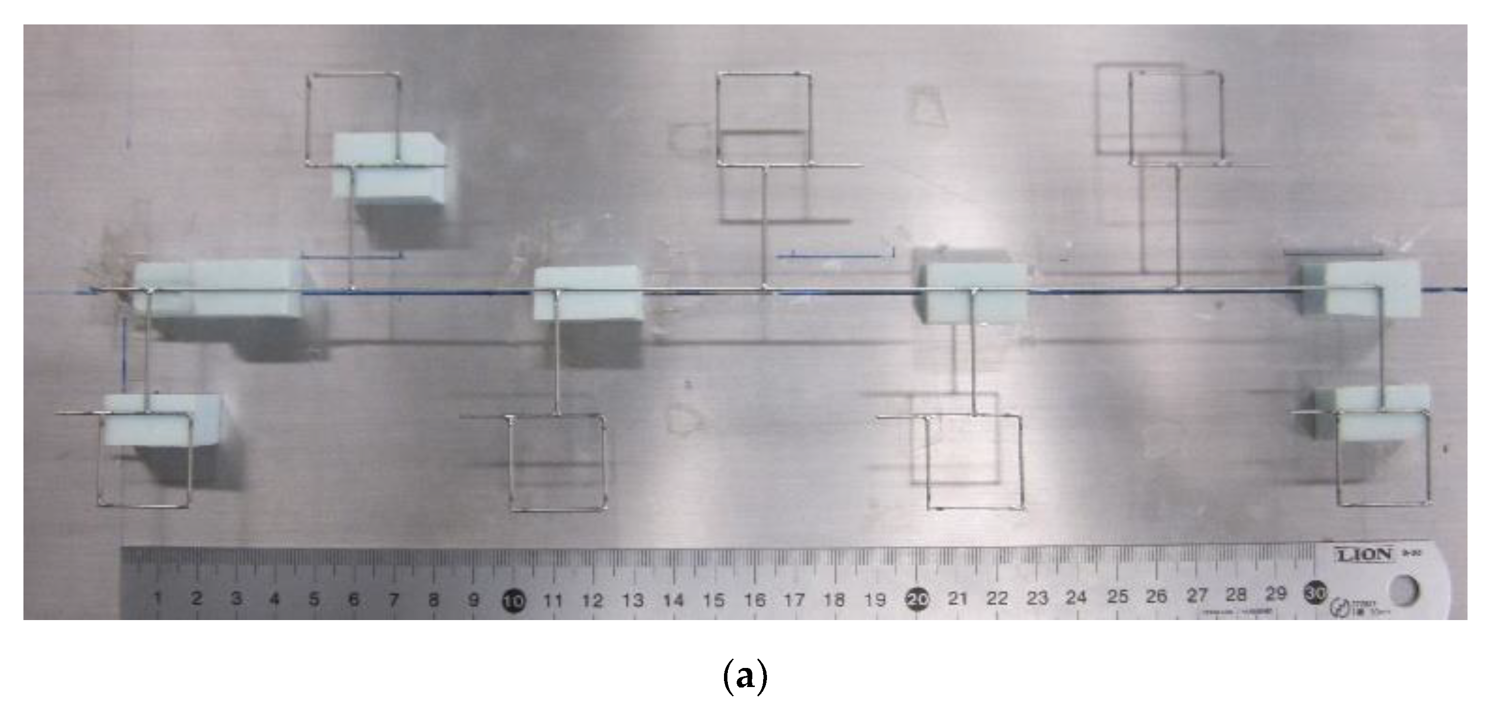
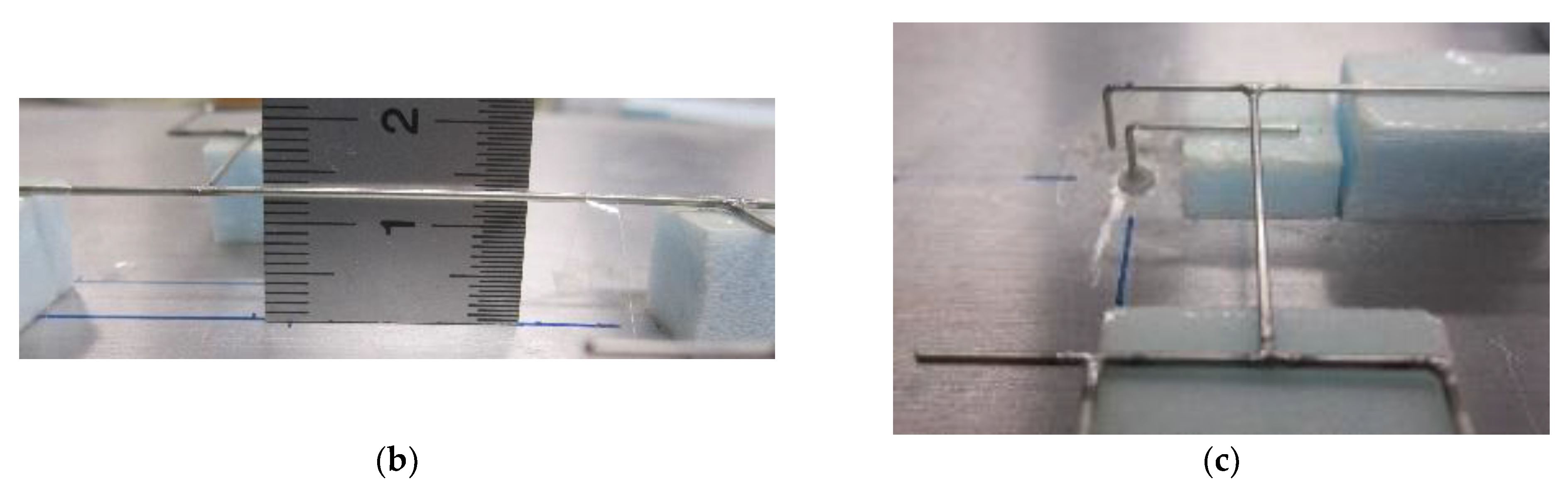
A final consideration is given to validating the simulated results. For this, we fabricate a modified antenna at f0 = 3 GHz using a ground plane of 9λ0 × 3λ0. The prototype’s photographs are shown in Figure 10. Small circles and dots in Figure 8 and Figure 9 show the experimental results. They are in good agreement with the simulated results. Our measurement system knows the radiation phase using a vector network analyzer (Anritsu MS46322A) as a transmitter and receiver. We calculate the axial ratio using the phase and check if the antenna radiates a CP wave.
We compare our results with those of other research groups. The comparisons are summarized in Table 1. The present antenna has the advantage that it does not require a matched termination. This advantage results in a higher gain even for a few periods than an antenna requiring the matched termination.
4. Conclusions
We have analyzed three line-antennas with loops. Analyses reveal that segment length Ls is one of the critical parameters of bent and branched line antennas for CP radiation. For the bent line antenna, Ls is influential in both the beam direction and axial ratio, while Ls is influential in only the axial ratio for the branched line antenna. Subsequently, we designed another branched line antenna modified with additional loops. It is demonstrated numerically and experimentally that loop addition results in a gain enhancement of 2.0 dB without any change in design parameters and CP wave bandwidth of the original antenna.
A comparison with other CP antennas such as helixes has yet to be conducted.
Author Contributions
Conceptualization, K.H.; software, K.H.; validation, K.N.; investigation, K.N.; resources, K.H.; data curation, K.N.; writing—original draft preparation, K.H.; writing—review and editing, K.H.; visualization, K.H.; supervision, K.H. and H.N.; project administration, K.H. All authors have read and agreed to the published version of the manuscript.
Funding
This research received no external funding.
Institutional Review Board Statement
Not applicable.
Informed Consent Statement
Not applicable.
Data Availability Statement
The numerical and experimental data used to support the findings of this study are included in this article.
Acknowledgments
The authors would like to thank Blair Thomson for his invaluable assistance in preparing this manuscript.
Conflicts of Interest
The authors declare that there are no conflict of interest regarding the publication of this article.
References
- Volakis, J.L. (Ed.) Antenna Engineering Handbook, 4th ed.; MacGraw-Hill: New York, NY, USA, 2007; Chapters 11 & 20. [Google Scholar]
- James, J.R.; Hall, P.S. (Eds.) Handbook of Microstrip Antennas; Peregrinus: Stevenage, UK, 1989; Chapters 13 & 14. [Google Scholar]
- Hirose, K.; Nakatsu, M.; Nakano, H. A loop-line antenna with enhanced bandwidth of circular polarization. Int. J. Antennas Propag. 2020, 2020, 5216132. [Google Scholar] [CrossRef]
- Nakano, H.; Oka, T.; Hirose, K.; Yamauchi, J. Analysis and measurements for improved crank-line antennas. IEEE Trans. Antennas Propag. 1997, 45, 1166–1172. [Google Scholar] [CrossRef]
- Makimoto, T.; Nishimura, S. Circularly Polarized Microstrip Line Antenna. U.S. Patent 4398199, 9 August 1983. [Google Scholar]
- Mishra, G.; Sharma, S.K.; Chieh, J.S. A high gain series-fed circularly polarized traveling-wave antenna at W-band using a new butterfly radiating element. IEEE Trans. Antennas Propag. 2020, 68, 7947–7957. [Google Scholar] [CrossRef]
- Hirose, K.; Nakatsu, M.; Nakano, H. A loop antenna with enhanced bandwidth of circular polarization—Its application in a comb-line antenna. PIER J. C 2020, 105, 175–184. [Google Scholar] [CrossRef]
- Cameron, T.R.; Sutinjo, A.T.; Okoniewski, M. A circularly polarized broadside radiating herringbone” array design with the leaky-wave approach. IEEE Antennas Wirel. Propag. Lett. 2010, 9, 826–829. [Google Scholar] [CrossRef]
- Hirose, K.; Kimizuka, A.; Nakano, H. Microstrip-line antennas with loop elements. In Proceedings of the 2007 IEEE Antennas and Propagation Society International Symposium, Hawaii, HI, USA, 9–15 June 2007; pp. 721–724. [Google Scholar]
- Harrington, R.F. Fields Computation by Moment Methods; Macmillan: New York, NY, USA, 1968. [Google Scholar]
- Hirose, K.; Shibasaki, T.; Yoshida, Y.; Nakano, H. Ladder antennas for dual circular polarization. IEEE Antennas Wirel. Propag. Lett. 2015, 11, 1174–1177. [Google Scholar] [CrossRef]
- Kraus, J.D. Antennas, 2nd ed.; MacGraw-Hill: New York, NY, USA, 1988; Chapter 9. [Google Scholar]
- Balanis, C.A. Advanced Engineering Electromagnetics, 2nd ed.; Wiley: New York, NY, USA, 2012; Chapter 9. [Google Scholar]
- Hirose, K.; Sakurai, K.; Nakano, H. Circularly polarized loop-line antennas. IEICE Trans. 2002, J85-B, 1624–1632. [Google Scholar] [CrossRef]
- Hall, P.S. Microstrip linear array with polarisation control. IEE Proc. H 1983, 130, 215–224. [Google Scholar] [CrossRef]
Figure 1.
Antenna configurations: (a) perspective view; (b) bent line antenna having loops with a gap δ; (c) branched line antenna having loops without a gap (δ = 0); (d) modified branched line antenna with additional loops #n′; (e) side view with a vertical wire F-F′.
Figure 1.
Antenna configurations: (a) perspective view; (b) bent line antenna having loops with a gap δ; (c) branched line antenna having loops without a gap (δ = 0); (d) modified branched line antenna with additional loops #n′; (e) side view with a vertical wire F-F′.

Figure 2.
Antenna configurations in [3,7]: (a) bent line antenna [3]; (b) branched line antenna [7].

Figure 3.
Simulated beam direction and axial ratio versus segment length Ls for a bent line antenna with N = 12.
Figure 3.
Simulated beam direction and axial ratio versus segment length Ls for a bent line antenna with N = 12.

Figure 4.
Simulated axial ratio versus periodic number N.

Figure 5.
Simulated beam direction and axial ratio versus segment length Ls for a branched line antenna with N = 12.
Figure 5.
Simulated beam direction and axial ratio versus segment length Ls for a branched line antenna with N = 12.

Figure 6.
Simulated radiation pattern in ϕ = 0° plane for a branched line antenna with N = 4.

Figure 7.
Electromagnetic-coupling feed for impedance matching.

Figure 8.
Radiation pattern in ϕ = 0° plane for a modified branched line antenna with N = 4.

Figure 9.
Frequency responses of branched line antennas with N = 4: (a) axial ratio and gain; (b) VSWR for 50 Ω.
Figure 9.
Frequency responses of branched line antennas with N = 4: (a) axial ratio and gain; (b) VSWR for 50 Ω.


Figure 10.
Prototype of a modified branched line antenna with N = 4: (a) top view; (b) side view; (c) perspective view of an electromagnetic-coupling feed.
Figure 10.
Prototype of a modified branched line antenna with N = 4: (a) top view; (b) side view; (c) perspective view of an electromagnetic-coupling feed.


Table 1.
Comparisons with line antennas of other research groups.
| Line Type | Periodical Shape | Number of Periods | 3 dB Axial Ratio Bandwidth (%) | Gain (dBi) | Operating Frequency (GHz) | Matched Termination |
|---|---|---|---|---|---|---|
| bent [2,15] | rampart | 10 | − 1 | − 1 | 15 | R 2 |
| branched [6] | butterfly | 24 | 3.5 | 17 | 86 | R 2 |
| branched [8] | herringbone | 12 | 13 | 12.5 | 8 | R 2 |
| present | loop | 4 | 2.5 | 16.6 | 3 | N 3 |
1 Not described. 2 Required. 3 Not required.
Publisher’s Note: MDPI stays neutral with regard to jurisdictional claims in published maps and institutional affiliations. |
© 2022 by the authors. Licensee MDPI, Basel, Switzerland. This article is an open access article distributed under the terms and conditions of the Creative Commons Attribution (CC BY) license (https://creativecommons.org/licenses/by/4.0/).
Share and Cite
MDPI and ACS Style
Hirose, K.; Nakamura, K.; Nakano, H. Bent and Branched Microstrip-Line Antennas for Circular Polarization. Appl. Sci. 2022, 12, 1711. https://0-doi-org.brum.beds.ac.uk/10.3390/app12031711
AMA Style
Hirose K, Nakamura K, Nakano H. Bent and Branched Microstrip-Line Antennas for Circular Polarization. Applied Sciences. 2022; 12(3):1711. https://0-doi-org.brum.beds.ac.uk/10.3390/app12031711
Chicago/Turabian StyleHirose, Kazuhide, Kohei Nakamura, and Hisamatsu Nakano. 2022. "Bent and Branched Microstrip-Line Antennas for Circular Polarization" Applied Sciences 12, no. 3: 1711. https://0-doi-org.brum.beds.ac.uk/10.3390/app12031711
Note that from the first issue of 2016, this journal uses article numbers instead of page numbers. See further details here.