
Research on the Flow and Transmission Performance of Magnetorheological Fluid between Two Discs


1
Department of Mechanical Engineering, Chongqing University of Technology, Chongqing 400054, China
2
State Key Laboratory of Mechanical Transmission, Chongqing University, Chongqing 400044, China
*
Author to whom correspondence should be addressed.
Appl. Sci. 2022, 12(4), 2252; https://0-doi-org.brum.beds.ac.uk/10.3390/app12042252
Submission received: 14 January 2022
/
Revised: 17 February 2022
/
Accepted: 17 February 2022
/
Published: 21 February 2022
(This article belongs to the Special Issue Intelligent and Bionic Transmission in Machinery)
Abstract
:The viscoplastic flow of magnetorheological fluid in a disc was analyzed based on the Navier–Stokes Momentum Equation, and the yielded and unyielded decomposition surfaces were obtained. For the shear-thinning phenomenon of magnetorheological fluid, the magnetorheological properties of the magnetorheological fluid were described based on the Herschel–Bulkley model. Then, the relationship between torque, magnetic field, material, size and motion was established, and the magnetic field and working gap were optimized and analyzed. The results show that in the unyielding region, the magnetorheological fluid flows rigidly. In the yielding region, it flows as a viscous fluid. The degree of error of the proposed torque equation decreased gradually with the increase to current, as observed by experimental comparison.
1. Introduction
Magnetorheological fluid (MRF) is a solid–liquid two-phase smart material whose rheological properties are controlled by an applied magnetic field. It consists of a base fluid, additives and micron-sized magnetic particles uniformly distributed in the base fluid [1]. MRF can complete the reversible transition from a liquid to a solid-like state in milliseconds under a magnetic field. The shear yield stress and apparent viscosity of the material can be continuously controlled with the applied magnetic field [2]. As the magnetorheological effect transformation is reversible and easy to control, rapid response and other characteristics give MRF in the field of transmission an extensive range of application prospects [3]. Magnetorheological (MR) clutches, MR dampers, MR brakes, etc. are a new class of power transfer devices based on the rheological effect that use MRF as the power transfer medium and regulate torque through an applied magnetic field to achieve the purpose of output control [4,5].
Theoretical research and the structural designs of MR actuators are the focus of researchers currently exploring the practical engineering applications of MRF. Choi et al. [6] introduced the torque characteristics of electrorheological and magnetorheological clutches and conducted experiments on the response speed and durability of disc-type MR clutches to verify the feasibility of an MR transmission by comparing the experimental data of two types of clutches. Huang et al. [7] established a relationship expression between the magnetorheological effect generated by a cylindrical MR brake, the required volume of MRF and the minimum gap thickness, to provide a theoretical basis for the design of a cylindrical MR drive. Farjoud et al. [8,9] deduced the torque equation of a cylindrical MR brake at a high shear rate based on the Herschel–Bulkley model and determined the plug flow region in the working gap of MRF through modeling to obtain the relationship between the plug flow region and the viscous torque. Fernandez et al. [10] optimized the structural design of an MR clutch which used permanent magnets by means of a finite element simulation and adopted a multifaceted magnetic field blocking mechanism which significantly improved the torque transfer capability of the transmission. Rizzo [11] proposed a magnetic design method for MR clutches by applying nonlinear materials to amend the magnetic axial force direction of a permanent magnet system. Thakur et al. [12] performed magnetic field analysis for radial MR clutches with different slot types, summarized the relationship between torque performance, disc radius and magnetic field based on their experimental results, and optimized the design of the working gap. Zhang et al. [13] proposed a torque estimation method for disc-type MR devices that considered the centrifugal effects and introduced radial stresses into magnetorheological constitution analysis to improve the accuracy of torque evaluation. Wang et al. [14] presented a computational fluid dynamics simulation model for simulating the behavior of a wet MR clutch and validated the model with experimental data to complement the hardware-based MR clutch design process.
The above research was focused on discussing the influence of a single factor on the torque of MR device, but rarely analyzed the flowing nature of MRF, and rarely considered the shear-thinning phenomenon of MRF in its working process. In terms of device optimization, the analysis of the influence of multiple factors on the transfer torque is rarely considered. Especially in the question of the optimal arrangement of the magnetic field of MR devices, the magnetic field distribution in the working gap of an MRF is highly uneven, resulting in a low MR transfer torque. In order to solve the above-mentioned problems, the viscoplastic flow of the MRF in a disk-type gap was analyzed, and the torque equation was established considering the shear-thinning phenomenon of MRF. Based on electromagnetic field theory and the finite element method, the distribution of the magnetic field in the disc-type working gap of MRF was analyzed. The optimal magnetic field design scheme was obtained through structural adjustment. This article provides a valuable reference for the design and manufacture of disc-type MR transmission devices.
2. Design of an MR Transmission Device
The working principle of the disc-type MR transmission device is shown in Figure 1. The support shell is fixed with the frame by screws to ensure that the coil does not rotate relatively, and the thickness of the air gap between the support shell and the output disc needs to be taken into account. Copper gaskets and sealing packing in the transmission device are magnetic field-blocking parts that are used to improve the magnetic flux distribution. The MR transmission device work process is as follows:
- (1)
- In the initial state, the drive shaft starts to rotate under the action of the input torque from the power source. At this time, the excitation coil is not energized, and the torque transmitted by the zero-field viscosity of the MRF alone is not enough to drive the output disk to rotate.
- (2)
- After the excitation coil is energized, the magnetic flux generated by the coil passes through the gap of the MRF perpendicularly, the magnetic particles in the MRF are arranged into a chain structure along the magnetic flux direction, and the shear yield stress gradually increases, driving the output disk to start rotating. When the current increases, until the MRF reaches magnetic saturation, the device transmission torque reaches the extreme value and the driven-disc rotation remains stable.
- (3)
- In the event that the system needs to stop the power input, the coil is disconnected, and the shear yield stress of MRF decreases rapidly. Finally, the input disk and the output disk are disconnected, and the output disk stops rotating.
3. Analysis of Torque Performance
3.1. Analysis of MRF Flow
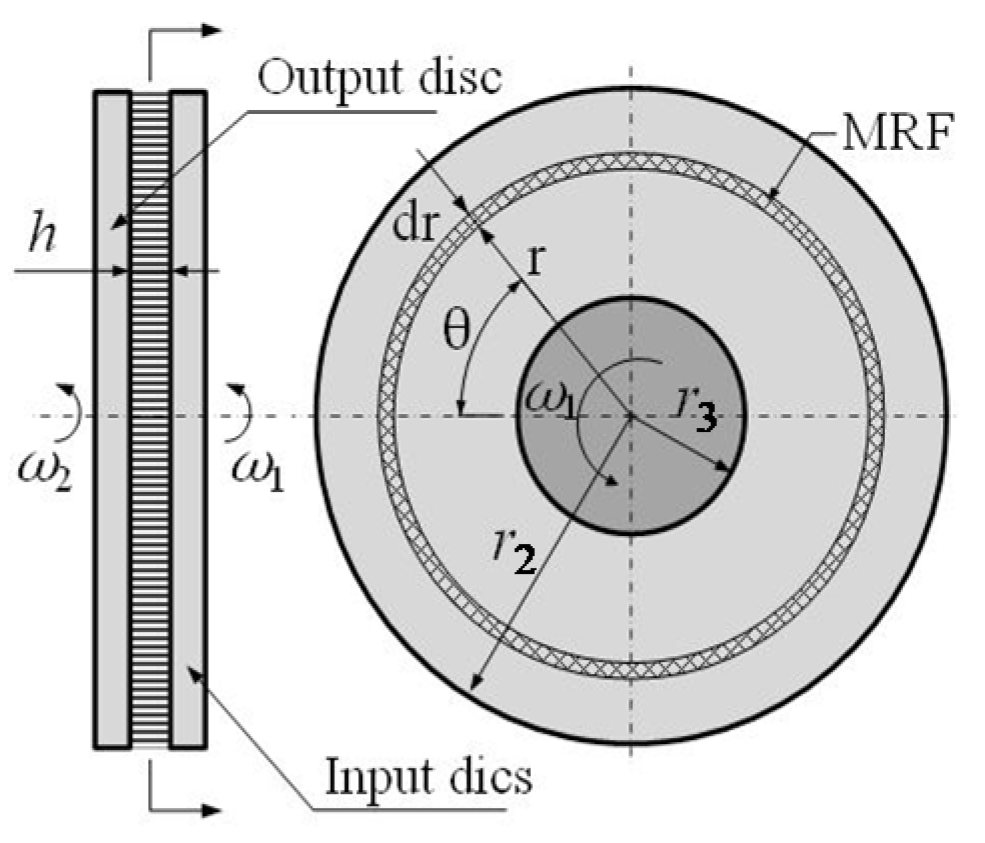
Figure 2 shows the shear model between disks and MRF. Consider two discs with radius r and distance h (h << r), where the working gap between the discs is filled with MRF. The right disc rotates along the z-axis with angular velocity ω1 and the MRF between the discs is sheared, which drives the output disc to rotate with angular velocity ω2.
As the working disk in the sudden change of speed, the impact of the working disk rotation on the fluid with time changes shows a certain hysteresis. The inertial force and vibration of the MRF during the drive process have some influence on the flow of the MRF, which increases the uncertainty of the MRF transient analysis [15]. Therefore, to negate the effect of response time on MRF flow, the steady-state assumption is used to analyze the parallel flow of the MRF in the working gap between the two disks. The following conditions are assumed: (1) the MRF is considered incompressible; (2) the flow of the MRF is steady-state; (3) there is no flow of the MRF in the radial direction; (4) the flow of the MRF is only a function of the radius; (5) ignore the volume force; (6) the magnetic field strength is uniformly distributed in the working gap; (7) the pressure in the MRF is along the thickness direction invariant; and (8) ignore the inertial force.
According to the above assumptions, in the cylindrical coordinate system (r, θ, z), the distribution of the flow velocity is assumed to be
where vr, vθ and vz are the velocities along the radius direction, rotation direction and thickness direction, respectively, and ω(z) is the angular velocity of the MRF in the thickness direction, which is a function of z.
Assume that the pressure gradient along the rotation direction is dp/dθ. For constant flow, ∂vθ/∂t = 0, there is no change in the r direction. The flow equation along the θ direction can be expressed as [16]
where η is the apparent viscosity of the MRF, which is related to the magnetic field strength H, and can be expressed as:
where τzθ is the dynamic shear yield stress of the MRF and is the shear strain rate.
Integrating Equation (2):
The flow boundary condition is:
After determining the integration constant according to the boundary conditions, the distribution of the flow velocity along the thickness direction of the MRF can be expressed as:
As can be seen from Equation (6), the flow of magnetorheological fluid can be divided into three forms according to different values of pressure gradient: (1) unyielding, the rigid–plastic flow of the MRF; (2) the shear-yielding flow of the MRF caused by the relative rotational speed of the two discs, with a linear distribution of flow velocity along the thickness direction of the MRF; and (3) the pressure flow of the MRF caused by the squeezing pressure, with a parabolic flow velocity along the thickness direction of the MRF distribution.
The case where the MRF is used for continuous flow is discussed below. Assuming that the volume flow rate per unit width is Q, the volume flow rate along the cross-sectional area integrated by Equation (5) can be obtained as
Suppose the thickness of MRF at p = pmax is h0, and dp/dθ = 0 at h = h0. The flow rate at this cross section can be expressed as
When the MRF flows continuously, the flow rate of each section is equal, and the gradient of pressure along the rotation direction is thus
Since the two flat plates are parallel, h = h0, and neither viscosity η nor (ω1 + ω2) is equal to zero, it can only be the case that dp/dθ = 0. When the magnetic field strength H varies, the magnetic shear yield stress of the MRF is τy(H). The interface of σzθ = τy(H) is defined as the decomposition surface of the yielded and unyielded regions. Assuming that zy is the dimension at the decomposition plane between the yielded and unyielded regions, the Navier–Stokes Momentum Equations for the MRF flowing between the two slit flat plates as circumferential shear are [17] (pp. 115–118).
where σθθ is the tangential pressure along the θ direction and τrθ and τzθ are the shear stresses of the MRF.
Since the angular velocity is constant along the flow direction, τrθ = 0. Since the two flat plates are parallel to each other, the pressure σθθ is constant, and the above equation can be simplified as
From Equation (11), it can be determined that τzθ is a constant, independent of z. Suppose the load torque on the driven shaft is TL, and the shear stress of the MRF required to make the output disk rotate is τL, then
By the Integral Median Theorem, the integration of Equation (12) is
where τ* is the value of the shear stress at point r0 in the interval (r3, r2), and when (r2 − r3)/r3 << 1, τ* is approximately equal to the value at r0 = (r2 + r3)/2.
Based on the Bingham model, the dynamic shear yield stress after the yielding of the MRF is τ* = τy(H) + η0, where η0 is the zero-field viscosity at H = 0, and the shear strain rate is denoted as [18]
In the yielding region, the angular velocity is obtained from Equations (13) and (14) as
Integrating Equation (15) and taking the boundary conditions when z = 0, ω(z) = ω1
In the unyielding region, the angular velocity is
Taking the boundary conditions when z = zy, ω(z) = ω2, the dimensions at the decomposition surface of the yielded and unyielded regions can be obtained as
Meanwhile, the output angular velocity of the disc-type MR drive can be expressed as
As shown in Equation (19), when the structure, material and load of the disc-type MR drive are fixed, the output angular velocity of the device increases linearly with increasing shear yield stress.
3.2. Analysis of Torque
Due to the fact that the Bingham model can only effectively describe the rheological properties of the post-shear yield region and cannot describe the shear thinning phenomenon, in order to describe the phenomenon of the shear thinning or thickening of the MRF viscosity during shear rheology more accurately, the 1-D flow model of the MRF can be described by the Herschel–Bulkley model [8]
where m and k are constants greater than zero, which are determined experimentally, and m is the flow behavior index of the MRF. When m = 1, the Herschel–Bulkley model degenerates to the Bingham model; when m < 1 (or m > 1), the shear thinning (or thickening) of the reacting liquid is observed. The equivalent zero-field viscosity in the Herschel-Bulkey model is
For the flow of the MRF between two discs, assume that the working area of the disc is a ring of radius from r3 to r2, and take a micro-circular area dA at radius r; since dA = 2πrdr, the torque M transferred by the whole disc can be expressed as
From the Herschel–Bulkley model shown in Equation (20), the torque M generated by the magnetorheological fluid after yielding can be composed of two parts, which are the magnetic torque MH generated by the MRF magnetic shear-yielding stress and the viscous torque Mη generated by the MRF viscosity.
Combining Equations (20) and (22), the torque MH transferred due to the shear yield stress generated by the chain-formation mechanism of the MRF is
Combining Equations (20)–(22), the viscous torque Mη transferred due to the shear yield stress generated by the viscosity of the MRF is
Therefore, the torque M transferred by the MRF between the two discs can be expressed as
4. Design and Analysis of Magnetic Fields
4.1. Magnetorheological Fluid Properties
The MRF used in this article was MRF-1 [18] and the material parameters are shown in Table 1. The relationship between the shear yield stress τy(H) and the magnetic field intensity H is derived from the experimental data, as shown in Figure 3.
From Figure 3a, it can be seen that the shear yield stress grows approximate linearly along with the increase of magnetic field intensity when the magnetic field intensity is lower than 100 kA/m. MRF starts to express the magnetic saturation phenomenon when the magnetic field exceeds 100 kA/m, at which point the shear yield stress changes more flatly with the magnetic field. The relationship between the magnetic field intensity H and the magnetic shear yield stress τy(H) is established from Figure 3 and fitted to the corresponding equation as
According to Figure 3b, it can be concluded that the viscosity of MRF decreases with an increase to the shear rate, and the phenomenon of shear thinning occurs. M = 0.75 and k = 0.085 Pa·sm were derived from the experimental data, as the speed error Δω was 10 rad/s.
4.2. Simplified Model of the Magnetic Circuit
According to the magnetic Ohm’s Law [19], we performed a magnetic field analysis of the working gap of the transmission device. The simplified equivalent model of the transmission device and the equivalent model of the magnetic circuit of radii r1~r7, the widths L1~L4, magnetoresistances R1~R9, etc., are shown in Figure 4 and Table 2.
The input disk, output disk and support shell of the MR drive are made of Steel-1020, the material of the drive shaft and driven shaft are Q235, the surrounding is set as an air boundary. and the thickness of the working gap is h. The thickness of the air gap h′ at R3 and R8 was 0.35 mm. According to the magnetic Ohm’s Law, the magnetomotive force Fm generated by the excitation coil is [20] (pp. 256–257)
where N is the number of turns of the coil (t) and I is the current passed into the excitation coil (A).
The ratio of the magnetomotive force Fm to the magnetic flux Φ is defined as the magnetic reluctance R.
From Figure 4, the magnetic circuit can be divided into a total of eight parts, labelled 1~9 [19], and the magnetoresistance of each part is
where μ1 and μ2 are the absolute permeability of Steel-1020 and MRF, respectively, and μ = μ0μr.
The total magnetoresistance of the magnetic circuit RM is obtained by summing up the magnetoresistance of each segment as follows
Therefore, the total magnetic flux of the whole magnetic circuit is
According to Kirchhoff’s Law, the magnetic flux density in the working gap is
Substituting Equation (30) into Equation (31), the relationship between magnetic induction and current can be obtained as
From the conversion relationship between magnetic flux density B and the magnetic field strength H [20] (pp. 248–251), the relationship between the magnetic field intensity H(I) of the working gap of the MRF and the current I of the coil is
where N is the number of turns of the excitation coil and μ0 is the vacuum permeability. Taking μ0 = 4π × 10−7 N/A2, μr is the relative permeability of the MRF, which is related to the volume fraction, diameter size and temperature of the magnetic powder particles in the MRF, and which can be measured experimentally [21,22].
Combined with Equations (19) and (33), the change to the output angular speed is positively correlated with the increase to the current when the load torque is constant, and the MR drive output speed is at its maximum when the current increases to the point of magnetic saturation of the MRF [23]. Define the distance between the yielded and unyielded partition interface of the magnetorheological fluid to the input disk as the yielded thickness hτ. The working gap thickness of MRF h is set to 1.0 mm, and the maximum transferable torque is 130 N·m. From Equation (13), it can be known that when the transmission is at full load and the speed difference Δω is 0 rad/s, the required minimum MRF shear yield stress τmin can be expressed as
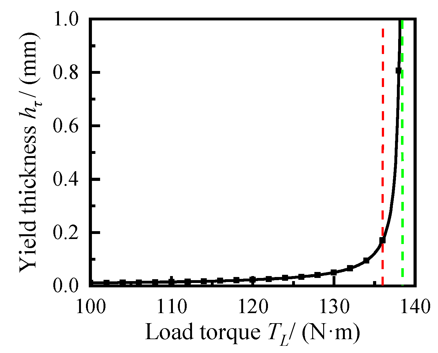
when the MRF is in a non-yielding state, zy = 0, τmin = 37.54 kPa. Therefore, when the magnetic shear yield stress is 38 kPa, the load torque TL and the yield thickness of MRF hτ are shown in Figure 5.
As can be seen from Figure 5, when the load torque is 136.1~138.2 N·m, the MRF transitions from a rigid–plastic flow state to shear yield flow state, and the yield thickness of the MRF multiplies from 0.18 mm to 1 mm; the MRF is wholly in shear yield at TL = 138.2 N·m. The partial yielding flow of the MRF occurs in a narrow range as a transition between the unyielding and fully yielding states.
4.3. Analysis of Magnetic Field
From Equations (26) and (33), it can be seen that the magnetic field intensity is related to the current, the working gap size, and the permeability of materials. The calculations were performed for the above variables to determine the magnetic field strength in the working gap.
The minimum magnetic field intensity Hmin = 67.82 kA/m within the MRF gap under a rated load was obtained by bringing τ = 38 kPa into Equation (26). Assuming that no magnetic saturation occurs in all parts of the MR drive, and the materials of the input disc, output disc and support shell are Steel-1020, the relative permeability of the housing and MRF are 1200 and 5, respectively. From Equation (29), the magnetoresistance is 1.06 × 10⁵ H−1. The design value of the coil parameter NI is 1500 A·t for a magnetic induction intensity H greater than 67.82 kA/m in the working gap of the MRF.
The relative magnetic permeability μr of the material changes with the magnetic field intensity H when the current of the excitation coil changes. In order to improve the accuracy of the magnetic field analysis, the Finite Element Method (FEM) was used to simulate the magnetic field in the whole working gap. Set the number of turns of the coil N = 500 t, the coil was placed through the currents from 1~4 A, respectively. The 2D axisymmetric model in Figure 4 was divided into 8909 cells using a 2D triangular mesh. We analyzed the influence of the copper gaskets on the transmission using the FEM, obtaining the results shown in Figure 6 and Figure 7.
As presented in Figure 6 and Figure 7, the overall magnetic flux distribution within the working gap of the MR transmission is uniform, and the working gap can be divided into four segments according to the variations in the magnetic field intensity. When the working gap radial distance r is from 0 to 5 mm, the magnetic field intensity increases rapidly to extremum with increases to the radial length. As the working gap radial distance is located in the two segments of r = 5~20 mm and r = 30~45 mm, the magnetic field intensity curve changes relatively smoothly and the magnetic field is more stable. With the radial distance from 20 mm to 30 mm, the magnetic field intensity curve decreases rapidly to 10 kA/m in the packing seal barrier interval. While r ranges from 45 to 50 mm, the magnetic field declines exponentially from the stable value.
In the absence of copper gaskets, the magnetic field in the working gap of the MRF on both sides is asymmetric. The maximum values of magnetic field intensity were 29.51 kA/m, 42.62 kA/m, 49.47 kA/m and 54.67 kA/m when the currents were 1.0 A, 2.0 A, 3.0 A and 4.0 A, respectively. The differences between the maximum values of the magnetic field strength on both sides were 3.28 kA/m, 3.87 kA/m, 4.0 kA/m and 6.1 kA/m, respectively. The magnetic field strength increased gradually with the increase of current, but the magnetic field was not uniform on both sides.
The magnetic field in the working gap was more uniform and the mean value was larger when the copper gaskets are added, and the maximum values of the magnetic field intensity were 43.0kA/m, 59.26 kA/m, 67.25 kA/m and 73.74 kA/m when the currents were 1.0 A, 2.0 A, 3.0A and 4.0 A, respectively. The differences between the maximum values of the magnetic field intensity on both sides were 0.25 kA/m, 0.29 kA/m, 0.05 kA/m and 0.03 kA/m. The magnetic field intensity increased gradually with the increase of coil current and it reached the design requirement at 3A. Furthermore, the magnetic field strength increased by 45.71%, 39.04%, 35.94% and 34.88%, compared to the values obtained without the isolation washer, respectively, when the coil current was the same.
In summary, for optimal torque characteristics, the working gap thickness of MRF h is 1.0 mm, the number of turns of the coil N is 400 t, and the current I is 0~3 A. These measurements were used as as the final optimization scheme of the transmission device.
4.4. Flow Analysis of Magnetorheological Fluid
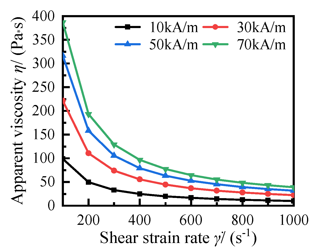
According to Equations (3) and (20), the apparent viscosity η of the MRF after yielding is
From Equation (35), it can be observed that the apparent viscosity of MRF is inversely proportional to the shear strain rate. Along with the increased magnetic field intensity, the effect of zero-field viscosity η0 on the apparent viscosity becomes smaller. When the magnetic field intensity is 10 kA/m, 30 kA/m, 50 kA/m and 70 kA/m, respectively, the relationships between apparent viscosity and the shear strain rate of the MRF were as shown in Figure 8.
As can be seen from Figure 8, along with the increase of magnetic field intensity, the effect of the shear strain rate on the apparent viscosity increases. The value of the apparent viscosity tends to stabilize when the shear rate is greater than 800 s−1.
To facilitate the analysis of the plug flow region (the unyielding region of the MRF), the ratio of the minimum shear yield stress τmin required by the load to the MRF magnetic shear yield stress τy(H) is defined as the plug flow coefficient λ. Then, λ can be expressed as
The magnetic field intensity data at 3A in Figure 7a was brought into Equations (26) and (36) to obtain the plug flow coefficient in the working gap, as shown in Figure 9, where hz is the distance across the gap, which indicates the distance between the plane where the MRF is located and the input disc.
As can be seen from Figure 9, when λ ≥ 1, the magnetorheological fluid is in the unyielding state, and it flows rigidly in the working gap. Since λ << 1 near the wall of the working gap of the transmission, the magnetorheological fluid near the wall of the working gap is in the yielding flow state. According to the plug flow coefficient in Figure 9a, the flow velocity distribution of the MRF in the working gap was plotted as Figure 9b.
From Figure 9b, it can be seen that the rotational speed of the disc-type magnetorheological transmission with the coil placed at one side is more related to the thickness of the gap, and the flow velocity distribution of the MRF in the unyielding region (regions A and B) is closer to the rotational speed of the input disc. In regions E, C and D, the magnetic field intensity is low, which leads to the yielding of the MRF, and the MRF is in a viscoplastic flow state. The flow velocity distribution in the cross section where the radius of disc r is 104 and 81 mm is intercepted in regions E and C, respectively, as shown in Figure 10.
The flow velocity of MRF varies widely along the thickness direction in the E, B, and C regions, the flow velocity does not decrease according to the linear law because the viscosity of the MRF undergoes shear thinning with the increase to the shear strain rate. The MRF in this region is not fully cured, which is one of the reasons for the unstable transmission performance.
According to the analysis of Figure 5, when the load torque is further increased, the magnetorheological fluid in the working gap changes from a rigid to a viscoplastic flow state. The load torque of the transmission was set to 137.7 N·m, the speed difference Δω = 22.74 rad/s was known from Equations (18) and (19), and the yield thickness was 0.52 mm. The flow of MRF in the working gap is shown in Figure 11.
As can be seen from Figure 11, the magnetic field intensity near the input disc was slightly greater than near the output disc when the shear yield stress required by the load exceeded the magnetic shear yield stress of the MRF. The MRF thus yields to flow near the output disc, and a rotational speed difference will appear. Figure 11b shows the flow velocity of the MRF in the cross section where the radius of the disc r was 89 mm, and the MRF in the yielding region was in a laminar flow state.
When hz > 0.52 mm, the MRF in the A region yields everywhere, and the flow rate of the MRF at this time is
When hz ≤ 0.52 mm, the magnetorheological fluid in the A region does not yield, and the magnetorheological fluid in in a solid-like flow state. At this time, when the flow velocity of the magnetorheological fluid is ω(z) = ω1, the input disk and the output disk rotate synchronously.
5. Comparative Experimental Study
5.1. Magnetorheological Torque Test
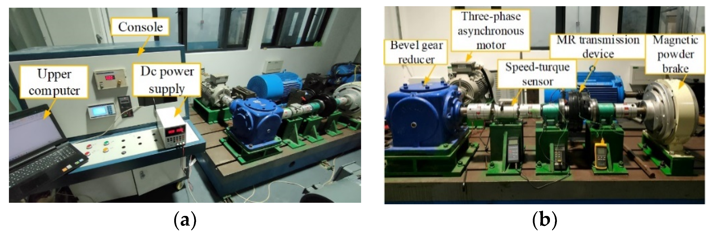
An MR transmission performance test bench was built to verify the correctness of the torque equation, as shown below (Figure 12).
The primary devices involved in the test system included a coupling, a ZH07 speed-torque sensor (range 500 N·m, indexing value 0.01 N·m, maximum speed 4000 rpm), a T16-1-L bevel gear reducer (transmission ratio i = 3), an MCK-S dynamic torque digital display meter, a magnetic powder brake, an RXN-3010D digital DC power supply, a YQ-3000-V7 inverter speed regulator, a 1LE0001-1DA4 three-phase asynchronous motor (power 18.5 kW, rated speed 2930 rpm), and a ZL3A-5S torque controller. The type of magnetorheological fluid was MRF-1 [18]. The internal structure of the MR drive is shown below (Figure 13).
5.2. Analysis of Experimental Results
During the experiment, different currents were passed into the excitation coil of the MR drive and the braking torque of the magnetic powder brake was continuously adjusted. The relationship between the current and the torque transmitted by the MRF was derived from the value measured by the torque sensor.
The Finite Element Analysis (FEA) results in Figure 7a were substituted into Equation (25), and the values obtained were r2 = 0.129 mm and r3 = 0.079 mm. The input disk speed ω1 was 100 rad/s, the output disk speed ω2 was 90 rad/s, the Herschel–Bulkley model coefficient m is 0.75, k was 0.085 Pa·sm and the thickness of the working gap h was 0.001 m. The relationship between the current passed into the excitation coil and the torque of the MR drive are shown in Figure 14.
As can be observed from Figure 14, the MR torque can be divided into roughly two stages according to the rate of change of the transmitted torque.
The transmission torque increased significantly with the current when the current was between 0.5 A and 1.5 A. When the current reached 0.5 A, the experimentally derived torque was 26.57 N·m, and the theoretically calculated torque was 48.99 N·m. The tested torque was 82.39 N·m when the current was 1.0 A, and the theoretically calculated torque was 93.10 N·m, with a transmission torque error of 11.50%.
The current I was in the range of 1.5 A to 3.0 A in the second stage. At this time, the torque of the transmission device increased slowly with the current. When the current was 3.0A, the experimentally derived torque was 129.84 N·m, and the theoretically calculated torque was 133.19 N·m with a torque error of 2.52%.
Due to problems such as the settling of the magnetic particles in the MRF [24], especially when the current is low, the magnetic force between magnetic particles decreased, the zero-field viscosity of the magnetorheological fluid and the shear yield stress under the action of the magnetic field decreased, the magnetorheological fluid performance was unstable, and the magnetic field distribution in the working gap was not uniform, resulting in a lower torque performance of the transmission than the calculated value.
The torque sensor was installed between the output disc and the magnetic powder brake, and the braking torque of the magnetic powder brake was set to 125 N·m. The input disc speed ω1 was controlled by the inverter and stabilized at 100 rad/s. The relationship between the current of the coil I and the output disc speed ω2 was determined according to the value taken by the speed–torque sensor and compared with the theoretical result of Equation (19).
As can be observed from Figure 15, when the current increased to 2.3 A, the output disk started to rotate under the shear yield stress of the MRF, and it grew linearly with the increase of current, with the yield flow area of the MRF decreasing. Because of the fluctuation of the motor speed and additional friction during the experiment, there were some errors between the experimental and theoretical values, but the overall trend was consistent. The results indicate that the magnitude of the current significantly affects the angular velocity distribution of the flow of MRF in the working gap.
6. Conclusions
In this research, magnetic field gap optimization and torque equation derivation were carried out for a disc-type MR drive. The equivalent reluctance was solved based on the magnetic Ohm’s Law, and the relationship between the magnetic field strength, coil current, structure size and material was derived. The magnetic flux distribution was analyzed by the FEA, and the maximum magnetic field strength in the working gap of the MRF was improved by the reasonable arrangement of magnetoresistive elements.
The working principle of the drive was elaborated, the flow velocity distribution of MRF in the working gap was analyzed, the output disc speed equation was derived based on the momentum equation, the torque equation of the disc MR drive was derived based on the Herschel–Bulkley model, and the shear torque generated by MRF at different currents was calculated. This research shows that:
- (1)
- When the coil is energized with DC current, the magnetic field strength under the steady-state magnetic field changes with the variations of the current, working gap size, and material magnetization, satisfying a cubic polynomial relationship with the shear yield stress of the MRF.
- (2)
- Magnetic field optimization through the reasonable use of magnetoresistive elements can effectively increase the torque performance of the MR drive and reduce the influence of the working gap thickness on the magnetic field. Under the same current, the magnetic field strength in the gap of the MRF can be enhanced by up to 45.71% through magnetic field optimization.
- (3)
- When the MRF has a continuous circumferential flow between two slit plates, the output angular velocity of the disc-type MR drive is positively correlated with the change in current, and the yield region of the MRF expands with the increase of the load torque, but does not satisfy the linear relationship.
- (4)
- When the torque of the drive is greater than the rated design value, the MRF rapidly changes from rigid flow to full-yield flow, and the partial yield flow state of the MRF exists only in a narrow torque zone. The flow mode of MRF in the yield flow region is laminar flow, and the flow velocity varies greatly with the thickness direction.
- (5)
- The trend of the experimentally tested curve was generally consistent with that of the theoretically calculated curve. The experimental comparison shows that the degree of error of the torque equation used in this paper decreases gradually with the increase of current.
Author Contributions
J.H. conceived this research; W.C. and J.H. deduced the calculation; W.C. wrote the original draft preparation; editing and review on this article was completed by R.S.; J.W. is responsible for overseeing the progress and visualization of the article. All authors have read and agreed to the published version of the manuscript.
Funding
This research was funded by the National Natural Science Foundation of China (NO. 51875068, NO. 51905060), the Science and Technology Research Program of Chongqing Municipal Education Commission under Grant (KJQN201901107), Natural Science Foundation Project of Chongqing Science and Technology Commission (cstc2020jcyj-msxmX0346), and the China Postdoctoral Science Foundation (2021M700619).
Acknowledgments
The authors would like to gratefully acknowledge the National Natural Science Foundation of China (NO. 51875068, NO. 51905060), the Science and Technology Research Program of Chongqing Municipal Education Commission under Grant (KJQN201901107), Natural Science Foundation Project of Chongqing Science and Technology Commission (cstc2020jcyj-msxmX0346), and the China Postdoctoral Science Foundation (2021M700619) for their support. Finally, the authors would like to thank the editors and reviewers for their valuable comments and constructive suggestions.
Conflicts of Interest
The authors declare no conflict of interest. And the funders had no role in the design of the study; in the collection, analyses, or interpretation of data; in the writing of the manuscript, or in the decision to publish the results.
References
- Spaggiari, A.; Castagnetti, D.; Golinelli, N.; Dragoni, E.; Scirè Mammano, G. Smart materials: Properties, design and mechatronic applications. J. Mater. Des. Appl. 2016, 233, 734–762. [Google Scholar] [CrossRef]
- Ashour, O.; Rogers, C.A.; Kordonsky, W. Magnetorheological Fluids Materials, Characterization, and Devices. J. Intel. Mat. Syst. Struct. 1996, 7, 123–130. [Google Scholar] [CrossRef]
- Kavlicoglu, B.; Gordaninejad, F.; Evrensel, C.; Fuchs, A. A semi-active, high-torque, magnetorheological fluid limited slip differential clutch. J. Vib. Acoust. 2006, 128, 604–610. [Google Scholar] [CrossRef]
- Phu, D.X.; Choi, S.-B. Magnetorheological Fluid Based Devices Reported in 2013–2018: Mini-Review and Comment on Structural Configurations. Front. Mater. 2019, 6, 19. [Google Scholar] [CrossRef]
- Sarkar, C.; Hirani, H. Theoretical and experimental studies on a magnetorheological brake operating under compression plus shear mode. Smart Mater. Struct. 2013, 22, 115032. [Google Scholar] [CrossRef]
- Choi, S.; Hong, S.; Cheong, C.; Park, Y. Comparison of Field-Controlled Characteristics Between ER and MR Clutches. J. Intel. Mat. Syst. Struct. 1999, 10, 615–619. [Google Scholar] [CrossRef]
- Huang, J.; Zhang, J.Q.; Yang, Y.; Wei, Y.Q. Analysis and design of a cylindrical magneto-rheological fluid brake. J. Mater. Process. Tech. 2002, 129, 559–562. [Google Scholar] [CrossRef]
- Farjoud, A.; Vahdati, N.; Yap Fook, F. Mathematical Model of Drum-type MR Brakes using Herschel-Bulkley Shear Model. J. Intel. Mater. Syst. Struct. 2007, 19, 565–572. [Google Scholar] [CrossRef]
- Farjoud, A.; Vahdati, N.; Fah, Y.F. MR-fluid yield surface determination in disc-type MR rotary brakes. Smart Mater. Struct. 2008, 17, 035021. [Google Scholar] [CrossRef]
- Fernandez, M.A.; Chang, J.-Y.; Huang, C.-Y. Development of a Passive Magnetorheological Fluid Clutch with Field-Blocking Mechanism. IEEE Trans. Magn. 2018, 54, 4601105. [Google Scholar] [CrossRef]
- Rizzo, R.; Musolino, A.; Bucchi, F.; Forte, P.; Frendo, F. Magnetic FEM Design and Experimental Validation of an Innovative Fail-Safe Magnetorheological Clutch Excited by Permanent Magnets. IEEE Trans. Energy Conver. 2014, 29, 628–640. [Google Scholar] [CrossRef] [Green Version]
- Thakur, M.K.; Sarkar, C. Investigation of Different Groove Profile Effects on Torque Transmission in Shear Mode Magnetorheological Clutch: Numerical Simulation and Experimental Study. J. Tribol. ASME 2021, 143, 091801. [Google Scholar] [CrossRef]
- Zhang, J.; Lu, S. Consideration of centrifugal effect in torque estimation for disc-type MR devices. Smart Mater. Struct 2018, 27, 105022. [Google Scholar] [CrossRef]
- Wang, P.; Katopodes, N.; Fujii, Y. Two-Phase MRF Model for Wet Clutch Drag Simulation. SAE Int. J. Engines 2017, 10, 1327–1337. [Google Scholar] [CrossRef]
- Mohammad, M.Z.; Mohammad, H.K.; Mahmood, N.; Amir, J. Parametric investigation of twin tube magnetorheological dampers using a new unsteady theoretical analysis. J. Intel. Mat. Syst. Struct. 2019, 30, 878–895. [Google Scholar] [CrossRef]
- Blanchard, D.; Ligrani, P.; Gale, B. Miniature Single-Disk Viscous Pump (Single-DVP), Performance Characterization. J. Fluids Eng. 2006, 128, 602–619. [Google Scholar] [CrossRef]
- Oertel, H. Prandtl-Essentials of Fluid Mechanics, 3rd ed.; Springer: New York, NY, USA, 2010; pp. 115–118. [Google Scholar]
- Sun, T.; Peng, X.; Li, J.; Feng, C. Testing device and experimental investigation to influencing factors of Magnetorheological fluid. Int. J. Appl. Electrom. 2013, 43, 283–292. [Google Scholar] [CrossRef]
- Song, W.-L.; Li, D.-H.; Tao, Y.; Wang, N.; Xiu, S.-C. Simulation and experimentation of a magnetorheological brake with adjustable gap. J. Intel. Mat. Syst. Struct. 2016, 28, 1614–1626. [Google Scholar] [CrossRef]
- William, H.; Hayt, J.; Buck, J.A. Engineering Electromagnetics, 8th ed.; McGraw-Hill Science: New York, NY, USA, 2011; pp. 248–251. [Google Scholar]
- Huang, J.P. New mechanism for harmonic generation in magnetorheological fluids. J. Phys.—Condens. Mat. 2004, 16, 7889–7894. [Google Scholar] [CrossRef] [Green Version]
- Bombard, A.J.F.; Joekes, I.; Alcântara, M.R.; Knobel, M. Magnetic Susceptibility and Saturation Magnetization of some Carbonyl Iron Powders used in Magnetorheological Fluids. Mater. Sci. Forum 2003, 416–418, 753–760. [Google Scholar] [CrossRef]
- Laherisheth, Z.; Upadhyay, R.V. Influence of particle shape on the magnetic and steady shear magnetorheological properties of nanoparticle based MR fluids. Smart Mater. Struct. 2017, 26, 054008. [Google Scholar] [CrossRef]
- Wen, M.; Chambers, J.; Sherman, S.G.; Wereley, N.M. Monitoring sedimentation of magnetorheological fluids using a vertical axis monitoring system with a low aspect ratio sensor coil. Smart Mater. Struct. 2019, 28, 025039. [Google Scholar] [CrossRef]
Figure 1.
Structure diagram of an MR transmission. (a) Schematic diagram, (b) Structure diagram.

Figure 2.
Circumferential flow of magnetorheological fluid (MRF) between two discs.

Figure 3.
Rheological characteristic curve of MRF. (a) Magnetic curve of MRF-1, (b) characteristics of viscosity.
Figure 3.
Rheological characteristic curve of MRF. (a) Magnetic curve of MRF-1, (b) characteristics of viscosity.

Figure 4.
Equivalent model of transmission device.

Figure 5.
Relationship between yield thickness and load torque.

Figure 6.
Cloud diagram of magnetic field intensity and magnetic vector potential at 3A. (a) h = 1.0 mm with copper gaskets, (b) h = 1.0 mm without copper gaskets.
Figure 6.
Cloud diagram of magnetic field intensity and magnetic vector potential at 3A. (a) h = 1.0 mm with copper gaskets, (b) h = 1.0 mm without copper gaskets.

Figure 7.
Relationship between current and magnetic field intensity. (a) h = 1.0 mm with copper gaskets, (b) h = 1.0 mm without copper gaskets.
Figure 7.
Relationship between current and magnetic field intensity. (a) h = 1.0 mm with copper gaskets, (b) h = 1.0 mm without copper gaskets.

Figure 8.
Relationship between apparent viscosity and shear strain rate.

Figure 9.
Flow of MRF in the working gap. (a) Plug flow coefficient of MRF, (b) flow velocity of MRF.
Figure 9.
Flow of MRF in the working gap. (a) Plug flow coefficient of MRF, (b) flow velocity of MRF.

Figure 10.
Flow of MRF in the working gap: (a) region E, (b) region C.

Figure 11.
Flow of MRF under incomplete yielding: (a) flow distribution in the whole working gap, (b) flow velocity of MRF in region A.
Figure 11.
Flow of MRF under incomplete yielding: (a) flow distribution in the whole working gap, (b) flow velocity of MRF in region A.

Figure 12.
MR transmission performance test bench: (a) control part, (b) testing part.

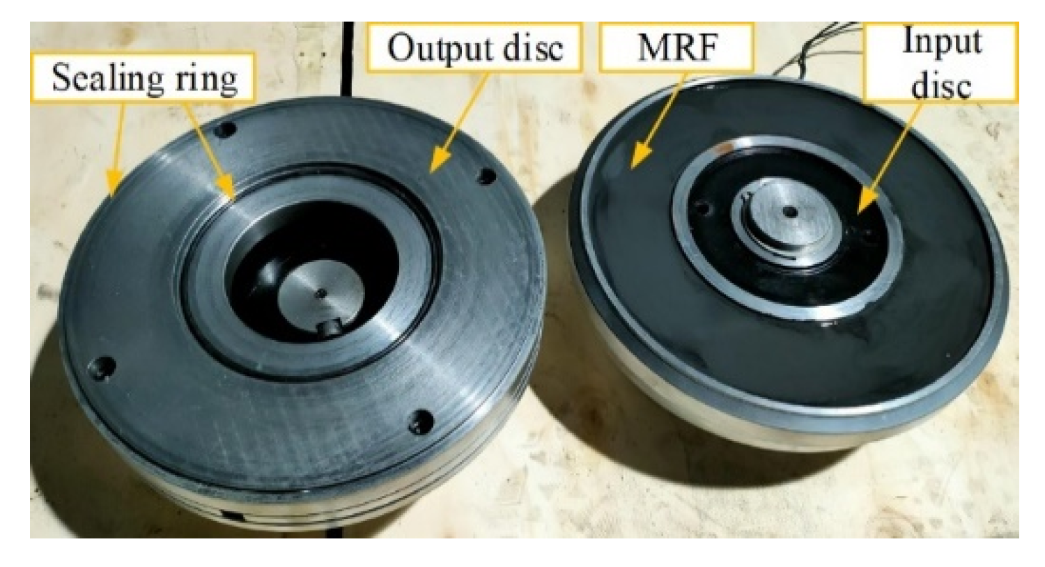
Figure 13.
Internal structure of the MR transmission device.

Figure 14.
Relationship between current and torque.

Figure 15.
Relationship between current and output disk speed.


Table 1.
Magnetorheological fluid (MRF-1) performance parameters.
| Volume Fraction/% | Additives Ratio/% | Base Fluid | Zero Field Viscosity/Pa·s |
|---|---|---|---|
| 5 | 1.4 | silicone oil | 0.12 |
Table 2.
Main dimensions of transmission device (mm).
| Parameter | Value | Parameter | Value |
|---|---|---|---|
| r1 | 135 | r7 | 125 |
| r2 | 129 | L1 | 10 |
| r3 | 79 | L2 | 26 |
| r4 | 73 | L3 | 12 |
| r5 | 83 | L4 | 25 |
| r6 | 92 | L5 | 4 |
Publisher’s Note: MDPI stays neutral with regard to jurisdictional claims in published maps and institutional affiliations. |
© 2022 by the authors. Licensee MDPI, Basel, Switzerland. This article is an open access article distributed under the terms and conditions of the Creative Commons Attribution (CC BY) license (https://creativecommons.org/licenses/by/4.0/).
Share and Cite
MDPI and ACS Style
Huang, J.; Chen, W.; Shu, R.; Wei, J. Research on the Flow and Transmission Performance of Magnetorheological Fluid between Two Discs. Appl. Sci. 2022, 12, 2252. https://0-doi-org.brum.beds.ac.uk/10.3390/app12042252
AMA Style
Huang J, Chen W, Shu R, Wei J. Research on the Flow and Transmission Performance of Magnetorheological Fluid between Two Discs. Applied Sciences. 2022; 12(4):2252. https://0-doi-org.brum.beds.ac.uk/10.3390/app12042252
Chicago/Turabian StyleHuang, Jin, Wenjian Chen, Ruizhi Shu, and Jing Wei. 2022. "Research on the Flow and Transmission Performance of Magnetorheological Fluid between Two Discs" Applied Sciences 12, no. 4: 2252. https://0-doi-org.brum.beds.ac.uk/10.3390/app12042252
Note that from the first issue of 2016, this journal uses article numbers instead of page numbers. See further details here.