Article

Microstructure and Phase Transformation Temperature of NiTiNb Shape Memory Alloy Prepared by Laser Solid Forming Using Mixed Powder

1
State Key Lab of Solidification Processing, School of Materials Science and Engineering, Northwestern Polytechnical University, Xi’an 710072, China
2
Shaanxi Key Laboratory of High-Performance Precision Forming Technology and Equipment, Northwestern Polytechnical University, Xi’an 710072, China
3
Yangtze River Delta Research Institute of NPU, Taicang 215400, China
4
Chengdu Aircraft Industry (Group) Corporation Ltd., Chengdu 610092, China
*
Author to whom correspondence should be addressed.
Submission received: 29 December 2021 / Revised: 22 January 2022 / Accepted: 17 February 2022 / Published: 24 February 2022
(This article belongs to the Special Issue Advanced Structure Materials and Processing)

Abstract

:
NiTiNb is a wide-hysteresis shape memory alloy. The Laser Solid Forming (LSF) technology can overcome the shortcomings of the traditional long cycle processing to prepare NiTiNb. In this work, we studied the microstructure and phase transformation temperature of the NiTiNb prepared by LSF., in which the Ni + Ti + Nb mixed powder was melted under different laser power P, scanning speed v, layer thickness t, and energy density EV. The results show that the combination of LSF process parameters with P = 2000 W and v = 900 mm/min can obtain a good metallurgical bond. As the laser power increases, the grain size increases, and the proportion of equiaxed crystals increases, the martensite transformation temperature increases. The inhomogeneity of the LSF-NiTiNb microstructure results in different phase transformation temperatures even in the same sample. The subsequent heat treatment at 850 °C for 3 h increases the phase transformation temperature and hysteresis of LSF-NiTiNb. The tensile properties of the LSF-NiTiNb samples with different building heights are significantly different. The maximum elongation reaches 8% and the minimum elongation is only 0.8%. The LSF parameter combination in this work has reference value for the parameter selection of subsequent preparation of NiTiNb.

1. Introduction

The combination of LSF parameters with P = 2000 W and v = 900 mm/min can obtain a good metallurgical bond. The microstructure of LSF-NiTiNb alloy is mainly composed of NiTi matrix and Nb phase, and Nb is mainly enriched in grain boundaries. As the laser power increases, the grain size increases, and the proportion of equiaxed crystals increases, the martensite transformation temperature increases. Heat treatment at 850 °C for 3 h will increase the phase transformation temperature and hysteresis of LSF-NiTiNb. However, the inhomogeneity of the microstructure results in different phase transformation temperatures in the same sample and the tensile properties of the LSF-NiTiNb samples with different building heights are also significantly different. The maximum elongation reaches 8% and the minimum elongation is only 0.8%.
NiTi-based shape memory alloy (SMA) is a smart material with shape memory effect (SME) and superelastic properties (SE). This is related to the reversible thermoelastic martensite transformation between the high-temperature austenite phase and the low-temperature martensite phase existing in NiTi-based shape memory alloys [1]. Because of the unique functional characteristics of NiTi-based SMA such as good biocompatibility [2], excellent corrosion resistance [3], excellent mechanical properties [4], NiTi-based SMA has a strong application potential [5] in aerospace [6], automation [7], medicine [8] as well as in daily life. NiTiNb shape memory alloy with Nb addition and NiTiFe shape memory alloy with Fe addition can be applied to pipeline connections of an aeroengine [9,10]. While NiTiNb has more potential because of the characteristics of wide hysteresis, the maximum phase transformation hysteresis temperature of pre-deformed NiTiNb alloy can reach 150 °C. A connector made of NiTiNb alloy can be stored, transported, and installed at room temperature, saving economic and time costs. Therefore, NiTiNb shape memory alloy has a wide range of application prospects and research value in aviation hydraulic pipeline connection systems. However, because of the characteristics of high work hardening, high toughness, high strength, and high ductility of NiTi-based SMAs [11], it is sensitive to processing parameters, so the workability is poor [12,13]. Powder metallurgy and casting usually cause pollution, chemical segregation, pores, and unsatisfactory functional properties [14,15,16]. It is difficult to manufacture NiTi-based components with complex structures using traditional processing techniques of subtractive or equivalent material manufacturing. This greatly limits its potential applications [17,18].
AM shows the reality of being able to transfer three-dimensional (3D) designs created on computers to a machine that can replicate the geometry into a physical object. We don’t need to consider the geometrical complexity or determine how each feature must be made and in what order, so AM has more advantages than conventional manufacturing like machining [19]. In aerospace field, a well-known example is the fuel nozzle for the GE LEAP engine which was manufactured by AM, when using AM, lead-time can be considerably reduced compared to conventional manufacturing. In volume production industries, such as the automotive sector, AM is able to prototype their models earlier and bring their products to the market as fast as possible [20]. In medical field, AM can convert patient-specific data for customized products and medical interventions [21]. Therefore, the use of AM technology to prepare NiTi-based alloys has attracted more and more attention [11,22,23,24]. In general, metallic AM techniques can be divided into three types based on heat source, i.e. laser-based AM and arc-based AM. In this field, wire and arc additive manufacturing (WAAM) using an electric arc as the heat source and metal wire as the feedstock has been applied to manufacture metallic components [25], and a series of related models have been developed to improve the accuracy of prepared components [26,27,28]. Laser-based AM using the laser as the heat source and the powder as the feedstock, and it gives better resolution and surface finish compared with WAAM [29]. Such as Selective Laser Melting (SLM) and Laser Solid Forming (LSF), also known as Laser-based Directed Energy Deposition (LDED) technology are two widely concerning technologies for preparing NiTi [22], SLM has high precision in preparing samples while LSF can build a larger sample volume, they gradually get more research because of their advantages. There are some works on the microstructure and phase transformation of NiTi or NiTiNb prepared by SLM or LSF. Hamilton RF et al. [22] found that NiTi alloys prepared by LDED appeared spatially varying composition. Bimber BA et al. [30] studied the distribution of precipitates in NiTi alloy prepared by LDED, they reported that the area fraction and size of Ni4Ti3 precipitates decreased as the z-height (building height) increased. The above research showed that the microstructure of the samples prepared by LDED changes with the building height, so we can speculate that the sample properties will also change with the building height. T. Bormann et al. [31] found that controlling the scanning speed can regulate the transformation temperature and controlling the laser power and scanning path can regulate the microstructure, that is, the shape and arrangement of grains and the grain size. S. Saedi et al. [32] found that NiTi alloy parts prepared by combining high laser power with high scanning speed or combining low laser power with low scanning speed often have high density. The above research mainly explained the relationship between the process parameters and the microstructure and phase transformation of the prepared samples. Recently, Igor Polozov et al. [33] explored the microstructure and phase transformation temperature of NiTiNb prepared by SLM, which provided a reference for us to prepare NiTiNb by LSF, they found that the microstructure of SLM-NiTiNb was composed of B2-NiTi matrix, fine NiTi+β-Nb eutectic phase and residual un-melted Nb particles, and the phase transformation hysteresis was increased by about 40 °C compared with the traditional cast NiTiNb alloy. Therefore, we can use the combination of process parameters for reference and expect the influence of LSF process parameters on NiTiNb microstructure and phase transformation to a certain extent.
In previous studies [11,31,34,35], the input energy density is often regarded as the key factor affecting the phase transformation behavior, and the phase transformation temperature increases with the increase of the energy density [36,37]. However, there are still some works that show that under the same energy density, there are significant differences in the phase transformation behavior of NiTi alloys [38,39]. Due to the complexity of potential physical phenomena in the process of AM preparation, such as large temperature gradient, extremely fast solidification, and complex thermal history, and the diversity of the combination of manufacturing process parameters, the prepared samples have great variability in microstructure and mechanical properties [40]. At the same time, the large thermal gradient in the AM process may lead to the accumulation of residual stress and deformation in the specimen [41]. The selection of different process parameters in AM preparation technology will change the microstructure, phase transformation temperature, and mechanical properties of the prepared components. In addition, due to the variability and diversity of additive manufacturing parameters, an inappropriate combination of parameters will lead to delamination and cracks. Therefore, the parameter combination has a great influence on the property of the component prepared by LSF. In traditional technology, such as the induction melting in vacuum atmosphere, has a long processing cycle and it is difficult to form complex components. Considering the connection application background of the NiTiNb SMA tube joint which has a complex structure, we note that LSF can provide a better method for preparing NiTiNb because of its advantage of rapid prototyping complex components. However, there are few reports on the properties of NiTiNb alloys prepared by LSF. So, the preparation of NiTiNb alloy by LSF has great research value and the work will provide guidance for using LSF to process complex NiTiNb SMA tube joints. Therefore, we selected a variety of parameter combinations to preliminarily explore the microstructure and phase transformation temperature of NiTiNb prepared by LSF, the results show that LSF can play a better role in the preparation of NiTiNb. Through experiments, we have obtained the feasible parameter combination of NiTiNb prepared by LSF, preliminarily obtained the microstructure and phase transformation temperature of NiTiNb prepared by LSF using mixed powder, which provides an experimental basis for the preparation of NiTiNb by LSF.
In this work, we explore the feasibility of preparing NiTiNb alloy by LSF using mixed powder, viz., elemental Ni, Ti, and Nb powders were mixed in the ratio of 47:44:9, and then NiTiNb alloys were prepared by seven LSF parameter combinations including laser power P, scanning speed v, layer thickness t, and corresponding energy density. The microstructure, phase transformation temperatures, phase transformation behaviors, and tensile properties of subsequent heat-treated LSF-NiTiNb were reported. According to the research results, some suggestions for preparing NiTiNb by LSF using mixed powder are put forward.

2. Experimental

2.1. Material and Process Parameters

LSF technology refers to the laser solid forming technology with synchronous material feeding as the main technical feature. It can realize the direct manufacturing of parts or molds. Its working principle is to layer the CAD files generated by the computer and transform the 3D manufacturing process into the accumulation of the 2D manufacturing process. The high-power laser scans the surface of the substrate in the set scanning direction to form a molten pool according to the set scanning strategy. Through the coaxial powder feeding device, the metal powder is blown into the molten pool, and the powder quickly melts and solidifies. As the scanning progresses, the cladding layers are fused and accumulated layer by layer to form three-dimensional metal parts [42].
The main parameters are laser power P (W), scanning speed v (mm/s), hatching spacing h (mm), layer thickness t (mm), volumetric energy density EV (J/mm3), etc. Volumetric energy density EV (J/mm3) refers to the energy absorbed by each volume of material during each layer scanning [43]. When not specified in this article, the laser energy input refers to the volumetric energy density, the calculation method is shown in formula (1):
E V = P vht
The powders used in additive manufacturing are pre-alloyed powders and mixed powders. By changing the ratio of the mixed element powder, the composition of the alloy can be easily adjusted. In particular, the cost is lower than that of pre-alloyed powder. Therefore, the use of mixed element powders as raw materials for additive manufacturing preparation is a very promising processing method [36]. The spherical nickel powder, spherical titanium powder, and niobium powder with a particle size of 150–300 meshes are uniformly mixed by a high-energy ball mill at the atomic ratio of 47:44:9 (parameter is 300 r/min, 7 h) to prepare NiTiNb mixed powder. SEM images of the powder are shown in Figure 1.
We use semiconductor laser LSF equipment, the laser spot diameter of which is 5mm. Then we use the mixed powder and TC4 substrate [44] to prepare the small size of 20mm × 10mm × 10mm and the larger size of 70 mm × 15 mm × 12 mm NiTiNb alloy, the preparation process is protected by argon. The parameter combination is shown in Table 1. The two-way scanning strategy (Figure 2) is adopted, and the next layer is rotated 90 degrees compared to the previous layer [24], the x-direction and y-direction are the scanning directions, and the z-direction is the building direction (BD). The physical map of the prepared samples is shown in Figure 3.

2.2. Characterization Method

The annealing treatment of samples L1–L8 is as follows (the sample L7 and the sample L8 are processed according to Figure 4):
  • Samples L1-L6 are heated to 950 °C and kept for 15 h;
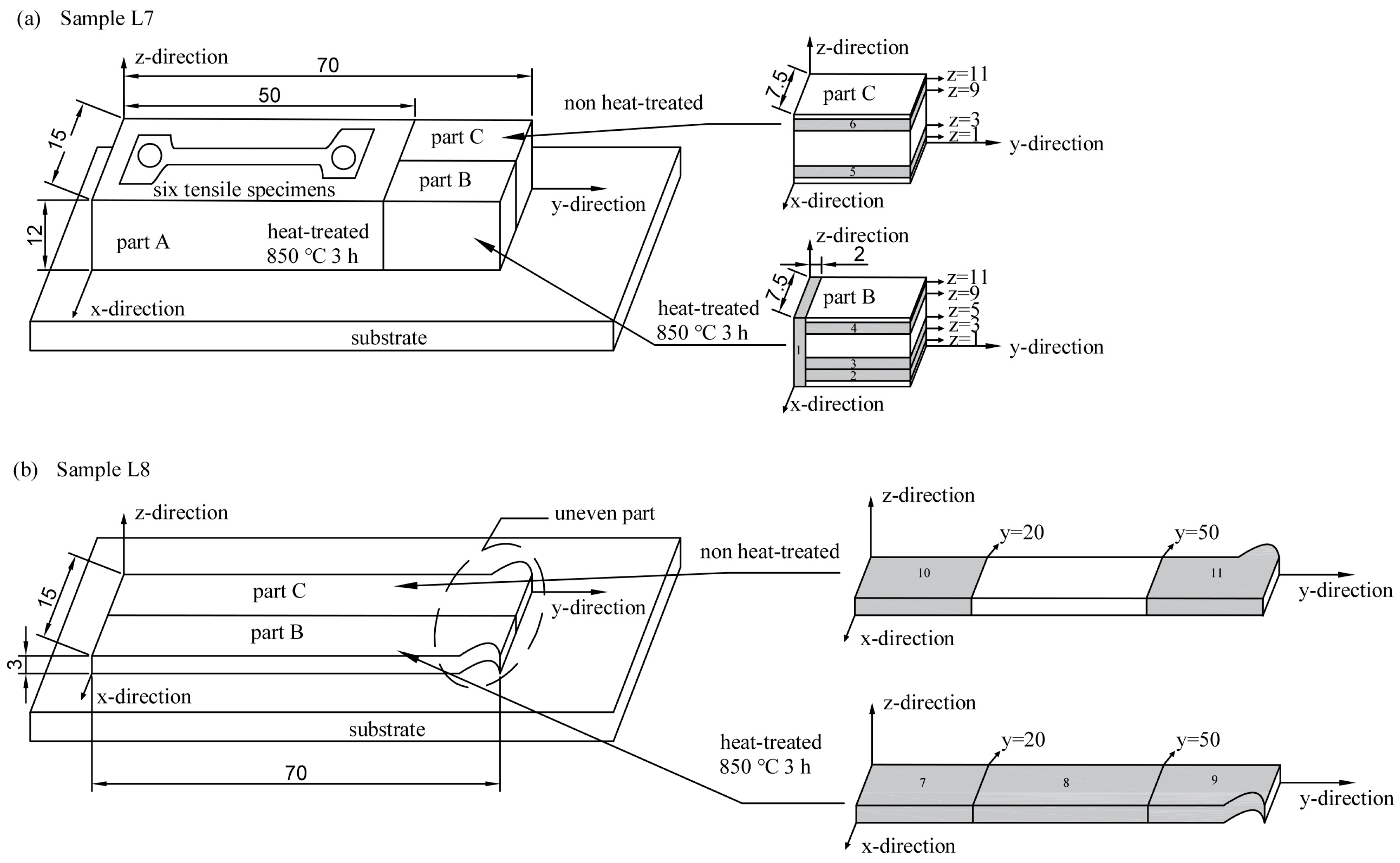
  • Sample L7 part A is heated to 850 °C and kept for 3 h;
  • Sample L7 part B is heated to 850 °C and kept for 3 h;
  • Sample L7 part C is not annealed;
  • Sample L8 part B is heated to 850 °C and kept for 3 h;
  • Sample L8 part C is not annealed.
First, the heat-treated samples L1–L6 are processed parallel to the building direction (z-direction) to obtain 2mm thick specimens for XRD, SEM, and 3 mm × 3 mm × 3 mm test blocks for DSC tests. The process of sample 7 and sample 8 is cumbersome, so we use Figure 4 to show it. Sample L7 and sample L8 are processed as follows according to Figure 4: we separate sample L7 and sample L8 from the substrate. For sample L7, we cut the tensile samples in part A and the CMT5205 electronic universal testing machine is used to test the L7 sample tensile property at 0 °C, all specimens are mechanically polished before testing. In part B, we take test block 1 which is parallel to the building direction (z-direction), take test block 2 (from z = 1 mm to z = 3 mm), block 3 (from z = 3 mm to z = 5 mm) and block 4 (from z = 9 mm to z = 11 mm), separately; In part C, we take test block 5 (from z = 1 mm to z = 3 mm) and block 6 (from z = 9 mm to z = 11 mm), separately. For sample L8, we take test block 7 (from y = 0 to y = 20 mm), block 8 (from y = 20 mm to y = 50 mm), and block 9 (from y = 50 mm to y = 70 mm) which are perpendicular to the building direction (z-direction) in part B, and take test block 10 (from y = 0 to y = 20 mm) and block 11 (from y = 50 mm to y = 70 mm) which are perpendicular to the building direction in part C. Secondly, after L1–L8 samples are processed, grinded on sandpaper, polished to obtain a mirror surface, and corroded (the corrosion solution is composed of hydrofluoric acid, nitric acid, and water at a ratio of 1:2:10), then are used for SEM observation, XRD observation, and DSC test (3 mm × 3 mm × 3 mm test blocks). The ZEISS Sigma 300 scanning electron microscope microscopy and LEICA vertical optical microscope are used to reveal the microstructure of LSF-NiTiNb. Phase structure is examined by SHIMADZU polycrystalline X-ray diffraction with Cu Kα radiation, the 2-theta is scanned in the range of 5–130 °C with a scan rate of 10 °/min. Phase transformation temperature is investigated by Netzsch DSC214 differential scanning calorimetry at a heating or cooling rate of 10 °C/min from −150 °C to 150 °C.

3. Results and Discussion

3.1. Microstructure Analysis of NiTiNb Prepared by LSF

3.1.1. Macroscopic Morphology

It can be seen from Figure 3 that the L1–L7 samples are well bonded to the substrate, while the L8 samples are separated from the substrate, and it can be seen from Figure 3 that spheroidization has occurred. Although the actual size accuracy of the samples is not high, the size accuracy of the samples prepared with the laser power of 1500 W and 2000 W in the small size samples is relatively good, and the samples do not appear serious oxidation. However, the actual size of samples L3 and L6 with a laser power of 2500 W deviate too much from the design size, and severe oxidation appears on the top of the sample, which is related to the excessively high power. When the scanning speed is 900 mm/min, the sample L7 with a laser power of 2000 W is close to the design size, and it is well combined with the substrate. The problem is that one side of the sample is warped, which indicates that internal stress has been generated during the preparation process. The sample L8 with a laser power of 1500 W is separated from the substrate and the bottom is uneven due to spheroidization, and the sample has a large degree of curvature. This is due to the low laser power and the difficulty to mix the powder completely evenly. When the size of the prepared sample is large, it is difficult for the laser to melt all the powder, so it is difficult to form a good combination between powder and powder. The composition of the powder is different from that of TC4 substrate, which may lead to poor metallurgical bonding due to unsatisfactory wetting. These will cause the samples to separate from the substrate or large warpage.
Under the same volumetric energy density, the line energy density [45,46] can also be used as a reference standard for energy input:
E L = P v
Under the same scanning speed, the line energy density of the high laser power is large. The formula calculation shows that the line energy density of sample L7 is EL7 = 133.33 J/m, and the line energy density of sample L8 is EL8 = 100 J/m. As the preparation process progresses, large residual stress will accumulate on the subsequent tracks, leading to the formation of cracks at the end of the part, so when processing long specimens, the end of the specimen will often break away from the substrate [47]. But increasing the input of line energy by increasing the laser power can increase the working temperature to completely melt the powder to form a dense deposit layer [8]. When the linear energy density is high, the high processing temperature can make the powder melt more fully. In the layer-by-layer process of LSF, the melting and solidification of the powder and the remelting and solidification of the previous layer occur in cycles. Therefore, the high linear energy density can form a tight combination between the layers of the sample. Therefore, L7 samples with high linear energy density can form close metallurgical bonding between layers during the melting–solidification–remelting-solidification process, so we can obtain a complete sample L7.
When LSF uses an energy density of more than 50 J/mm3 to prepare NiTi, a sample with a density of more than 90% can be obtained [8]. Compared with the powder bed system, the building volume of the powder feeding system is usually larger, so the LSF technology is easier to expand the building volume [48]. Observed from the morphology of the samples, it can be found that the combination of LSF process parameters with 2000 W laser power and 900 mm/min scanning speed can fully melt the Ni + Ti + Nb mixed powder, and the sample size will not deviate too much, and there is no serious oxidation on the surface, the powder, and the substrate can also form a good metallurgical bond when preparing larger size samples, so LSF has advantages when using Ni + Ti + Nb mixed powders.

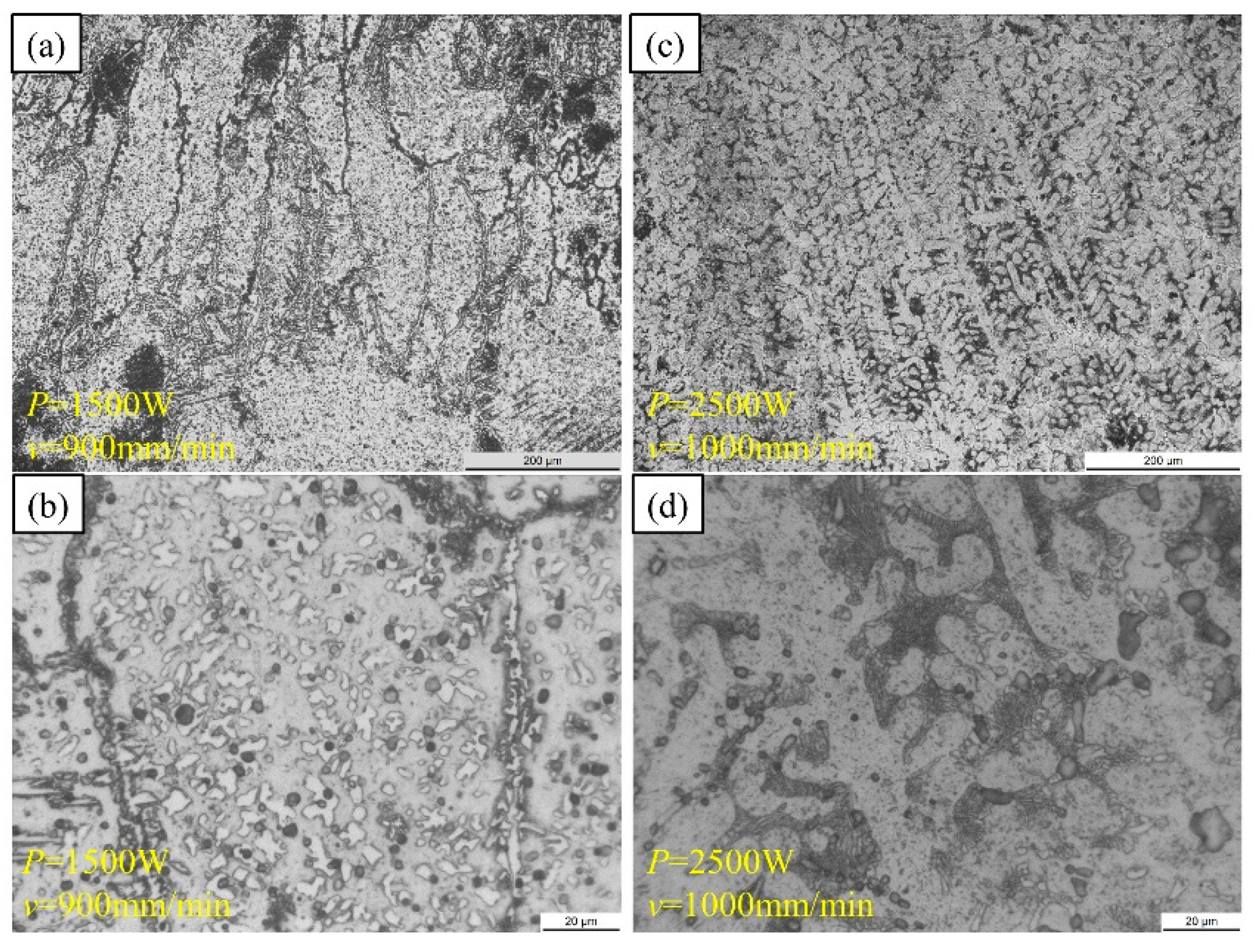
3.1.2. Microstructure Features

It can be seen from Figure 5 that there are B2 NiTi phase, Nb phase, and Ni4Ti3 phase in the samples prepared by LSF. The detection temperature is room temperature. Comparing the transformation temperatures (Table 2), it is found that the martensitic transformation start temperature (Ms) of the sample is 30 °C or above. The state of the sample should be a martensitic phase at room temperature, but B19′ phase is detected only in the L6 sample with P = 2500 W, v = 1000 mm/min, and EV = 33.33 J/mm3, The B2 parent phase still accounts for the majority, indicating that the high-temperature austenite phase is retained due to the rapid cooling rate during the preparation of LSF. It can be inferred that the samples prepared by LSF have uneven phase composition and element distribution in different building directions.
It can be seen from Figure 6 that because of the large energy input of sample L1, the molten pool is enlarged, the powder is exposed to high temperatures for a long time, and the grains are relatively coarse (Figure 6a). The dendrite structure grows in a preferred orientation, and the direction closest to the temperature gradient direction tends to occupy the most advantageous position in the dendrite growth. The dendrite microstructure with a large difference between the growth orientation and the temperature gradient direction disappears, and then presents directional dendrite growth along the building direction, as the energy input increases, the microstructure along the building direction evolves from short and thick columnar crystals to slender columnar crystals. The spheroidal particles in Figure 6f may be the etch pit caused by the corrosion process.
Figure 7 is a high magnification microstructure of the L1 and L6 samples. It can be found that there are many fine precipitated phases inside the grains of the NiTiNb alloy prepared by LSF. The L1 sample with a large energy input presents a cell morphology, and the L6 sample with a small energy input presents an obvious dendritic morphology, the eutectic region is obvious, and the grain size is smaller. During the process, layers have experienced constant remelting, and the grains in the remelted area are refined, and equiaxed grains are found in both samples.
Figure 8 shows the XRD curves of sample L7 position 1, sample L7 position 2, sample L7 position 4, sample L8 position 7 at room temperature. All four positions have been heat-treated (see Figure 4 for the position). Ni4Ti3 precipitation and B2 austenite phase are present in all positions, but the Nb phase is not detected in all positions, which indicates that the composition of the sample is unevenly distributed in space. The microstructure and phase transformation temperature of the sample parallel to the building direction are not the same, the range of reverse martensitic transformation start temperature (martensite begins to transform into austenite, As) of sample 7 is −31.5 °C to −24.1 °C, the range of reverse martensitic transformation finish temperature (martensite completely transforms into austenite, Af) is 13.7 °C to 23.5 °C, the test temperature of XRD is room temperature, which is between As and Af, and so we may consider with regard to the martensite detected in position 1 that the reverse martensite transformation is not completed and the martensite remains. It is considered that the martensite detected at position 7 may be the martensite phase caused by the repeated rapid solidification and stress caused by remelting during the preparation process and it is retained in the subsequent heat treatment.
The OM diagrams of sample L7 and sample L8 are shown in Figure 9. Compared with the microstructure parallel to the forging direction in the hot forged structure, which shows large and highly elongated grains [9,10], the NiTiNb microstructure prepared by LSF is closer to the cast microstructure. From the low magnification OM image, it can be observed that there are epitaxially grown columnar grains at position 1 parallel to the building direction [49] (Figure 9a). In the high-magnification OM image of this position, it is found that the crystal grain direction has changed during the growth of columnar crystals, and the sample microstructure no longer shows regular epitaxial growth, but grows along an irregular direction. Because the solid-liquid interface gradient will gradually change from the vertical laser scanning direction at the bottom of the molten pool to the scanning direction when the molten pool is solidified, the growth direction of the microstructure from the bottom to the top will change, and the adjacent layer is not prone to continuous epitaxial growth. During the preparation process, the temporal and spatial fluctuations of temperature cause the temperature gradient to deviate, and the microstructure will change in space [50]. Comparing the high-magnification OM microstructure of position 2 and position 4, it is found that in position 2 close to the substrate of sample L7 (Figure 9f), the grain size is larger, and in position 4 close to the top of the sample L7 (Figure 9g), the grain size becomes smaller, and the proportion of equiaxed grains increases. The grain size increases with the increase of laser power, but no obvious change is observed with the increase of laser scanning speed [51]. Figure 9f,h shows that as the laser power increases, the crystal grain size increases, and the proportion of equiaxed crystals increases. The martensite transformation temperature of the sample with reduced grain size will decrease [52], and the experimental results confirm the martensite transformation start temperature of position 7 is lower than that of position 2.
Figure 10 is the element distribution diagram of positions 1, 2 in sample L7 and positions 7 in sample L8. The structure of LSF-NiTiNb is similar to that prepared by traditional methods [53]. It is composed of NiTi matrix and β-Nb, eutectic β-Nb phase is obvious, meanwhile, large numbers of β-Nb precipitates densely distribute in the B2-NiTi matrix between eutectic regions. The difference is that the microstructure of LSF-NiTiNb parallel to the building direction (z-direction) presents epitaxial growth morphology, and the microstructure perpendicular to the building direction (z-direction) presents equiaxed crystal morphology, while most of the microstructure of the NiTiNb prepared by traditional methods presents irregular solidification structure, and most of the microstructure is columnar. In the three positions, a small amount of Nb is dispersed in the matrix and a large amount of Nb is enriched at the grain boundary. For the atoms of Ni: Ti: Nb, as shown in Table 2, during the preparation process, due to the high temperature, the evaporation of elements will occur, the evaporation of Ni in position 2 and position 7 (perpendicular to the building direction) is relatively more, and the content of Ti in position 1 (parallel to the building direction) decreases more, indicating that the element distribution of NiTiNb sample prepared by LSF is uneven, and the evaporation of elements is different at different building heights.
During preparation, the grains grow along the direction of the maximum temperature gradient, which is usually the same as the building direction (BD) [45]. In the additive manufacturing process, due to the inconsistency of temperature gradient, there are non-uniform nucleation and growth of equiaxed crystals and epitaxial growth of columnar crystals at the same time, which will produce a microstructure composed of coarse continuous columnar grains and fine inter columnar equiaxed grains [54]. Therefore, position 1 (Figure 10a) presents a discontinuous columnar morphology.

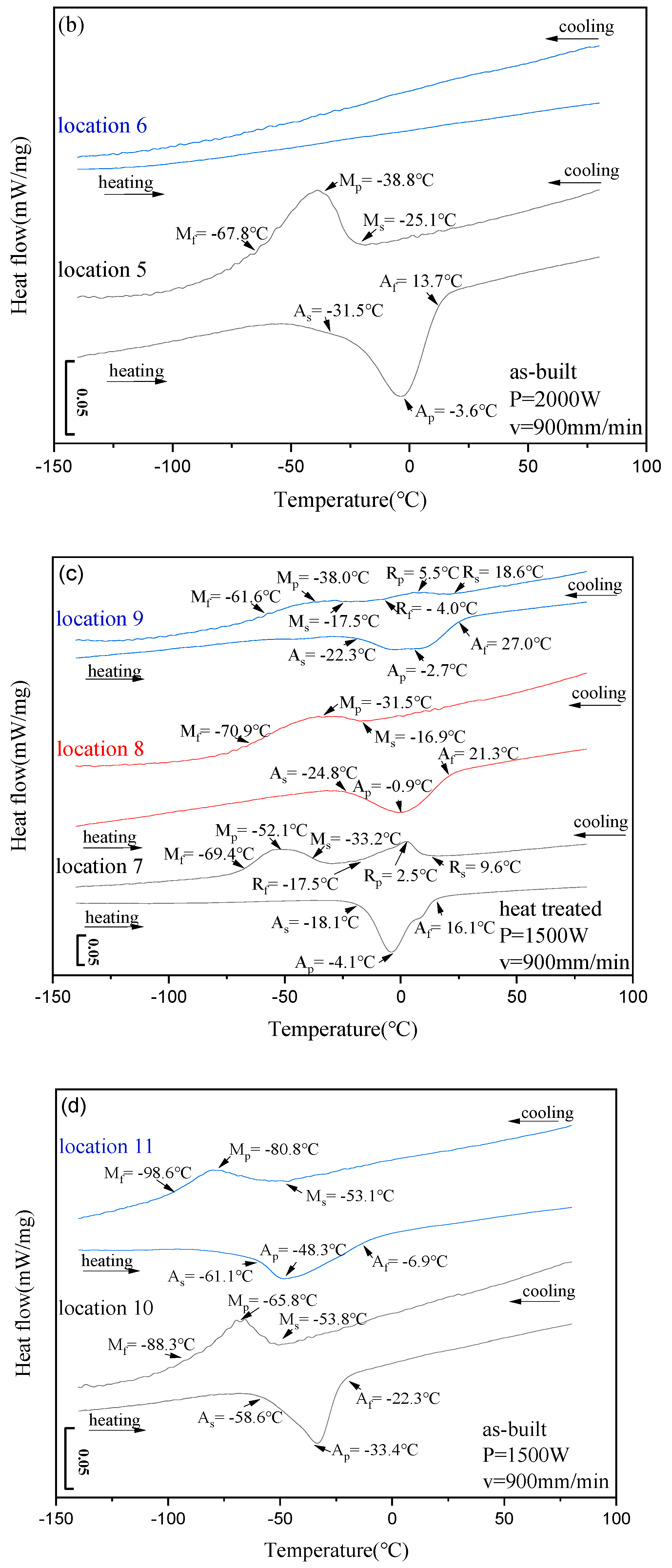
3.2. Phase Transformation of NiTiNb Prepared by LSF

The phase transformation of NiTiNb during heating and cooling is as follows: During cooling, when the temperature drops to the martensite transformation start temperature (Ms), austenite begins to transform into martensite, and this is called martensite transformation when the temperature continues to decrease to the martensite transformation finish temperature (Mf), the martensite transformation ends, and it is exothermic during cooling. During heating, when the temperature rises to the reverse martensite transformation start temperature (As), martensite begins to transform into austenite, and this is called reverse martensite transformation (austenite transformation). Continue to increase the temperature until the reverse martensite transformation finish temperature (Af), the reverse martensite phase transformation ends, and it is endothermic during heating. Mp and Ap correspond to the peak temperature of the forward and reverse transformation, respectively, indicating that about 50% of the transformation has occurred at this temperature. There are two transformation behaviors in NiTi, one is that B2 austenite directly transforms into B19′ martensite, called one-step transformation B2–B19′, the other is that B2 austenite transforms into R phase first, and then into B19′ martensite, called two-step transformation B2–R–B19′.
Figure 11 shows the DSC diagram of sample L1 and sample L6. The transformation temperatures (TTs) of samples are summarized in Table 3. Aging will produce a variety of precipitated phases. The precipitation of nickel-rich particles such as Ni4Ti3 in NiTi alloy will cause the change of Ni/Ti, thereby making the phase transformation temperature higher than room temperature. The diffusion of the Nb element will replace the Ni site in the matrix phase, causing a slight change in the atomic ratio of Ni/Ti in the matrix, which will also cause a change in the martensite transformation temperature. Although the process parameters of L1 and L6 are different, their phase transformation temperature values are very close except for the Mp and Ap values, which means that even if the energy density and the combination of process parameters are different, the phase transformation temperature may still be similar, so consider it may be that the heat treatment at 950 °C for 15 h had reduced the NiTiNb phase transformation temperature difference. This phenomenon also shows that after long-time heat treatment, the sample with small energy input needs to reduce or increase the temperature to reach 50% phase transformation. The phase transformation hysteresis temperature (AsMs) of sample L1 and sample L6 is only 3 °C, which does not exert the effect of the addition of Nb element on the wide hysteresis effect of NiTiNb alloy.
Under the heat treatment at 950 °C for 15 h, only L1 and L6 of the L1–L6 samples prepared by LSF show phase transformation behavior, but the L6 sample has poor forming accuracy (see Figure 3), therefore, we take the L1 process parameter combination as a reference, and considering that energy density is mostly considered to be an important factor affecting the structure and performance of the prepared samples, we choose energy density EV = 66.67 J/mm3, then reselect the process parameter combinations to explore. The long-term high-temperature heat treatment did not improve the phase transformation properties of L2–L5, Therefore, we appropriately lower the heat treatment temperature, reduce the annealing time, and choose 850 °C 3 h as the follow-up heat-treatment process.
The phase transformation curves of sample L7 and sample L8 are shown in Figure 12. The phase transformation temperatures at different locations are summarized in Table 4.
When the sample has not been heat-treated, the phase transformation temperature of the L7 sample with high laser power is higher than that of the L8 sample with low laser power, which may be related to the volatilization of Ni caused by high laser power, because the volatilization of Ni will increase the phase transformation temperature. Firstly, comparing Figure 12a and 12b, it is found that heat treatment will change the phase transformation behavior of the sample: from one-step B2–B19′ to two-step B2–R–B19′, and increase the characteristic temperature and phase transformation hysteresis. The characteristic temperatures related to martensitic transformation increase in a small range, the characteristic temperatures related to inverse martensitic transformation increase in a large range, and the transformation hysteresis (ApMp) increase by about 5.9 °C. Secondly, it can be seen from Figure 9a that the phase transformation behavior of the same sample after heat treatment is different at different building heights. The position of the sample close to the substrate is a two-step transformation; the middle position of the sample is a one-step transformation, and no phase transformation is detected near the top of the sample, which indicates that there is uneven microstructure in the building direction. However, no matter whether the sample is heat-treated or not, no phase transformation is detected near the top of the sample. It is speculated that the mixed powder near the top of the sample does not undergo a sufficient remelting process, and the uniformity of microstructure is damaged. The specific reasons need to be further explored. It is found that heat treatment changes the phase transformation behavior of the sample by comparing Figure 12c,d. Like sample L7, the phase transformation behavior of sample L8 also changes from one-step to two-step after heat treatment. The characteristic temperatures of phase transformation increase obviously, and the phase transformation hysteresis (ApMp) increases by about 2.8 °C. It can be seen from Figure 12c that the transformation behavior of the same sample after heat treatment is also different in the area perpendicular to the building height. R transformation occurs at both ends of the sample, and a small shoulder appears in the reverse martensitic transformation (austenite transformation), which may be related to the internal stress and high temperature during processing, similar to aging under pressure [55]. This indicates that the microstructure perpendicular to the building direction is also uneven.
Different combinations of LSF processing parameters will produce different microstructures, which will affect the phase transformation temperature. Heat treatment will increase the phase transformation temperature and change the phase transformation behavior. However, due to the non-uniformity of the microstructure of LSF prepared by mixed powder, the change degree at different positions of the sample is not completely consistent.
NiTi alloy powder melts and solidifies rapidly under the action of a high energy density laser as the preparation process proceeds, the previously solidified material undergoes a cyclic heating and cooling process. Therefore, the complex thermal history during the processing will lead to complex microstructures evolution [45], and the phase transformation behavior of NiTi alloy is very sensitive to microstructure changes [1], so the change of preparation process parameters will affect the microstructure of NiTi alloy and thus significantly affect the phase transformation. In previous studies, the input energy density is often considered to be the key factor affecting the phase transformation. Studies have found that the martensite transformation temperature generally increases with the increase of the input energy density [11,31,34,35,56,57,58,59]. Even under the same SLM energy density, the NiTi alloys prepared with different combinations of process parameters have a phase transformation temperature change of 205–277 K [38,39]. In the research of this article, it was also discovered that the phase transformation temperatures of NiTi prepared by different process parameters under the same energy density are not the same. Therefore, the input energy density is not the only factor that determines the quality of NiTi forming [46]. In this study, the phase transformation behavior of samples prepared with different process parameters is different and the phase transformation behavior of the same sample at different positions is also different [40]. After the samples were annealed at 850 °C for 3 h, not only did the phase transformation temperatures increase, but the phase transformation behavior also changes from one-step transformation to two-step transformation.
Aging leads to precipitation of Ni4Ti3 from the Ni-rich matrix, which reduces the Ni content in the NiTi matrix [55], thus increasing the phase transformation temperature [60]. In addition to affecting the phase transformation temperature, reducing the Ni content can also increase the thermal hysteresis width and phase transformation heat [5]. There is also another explanation that the change of Ni/Ti ratio caused by the loss of Ni is the main reason for the change of phase transformation temperature [31,39], and the decrease of Ni/Ti will cause the martensite transformation temperature to increase [5,45]. This is one of the reasons why the phase transformation temperature and the phase transformation hysteresis increase after the sample undergoes heat treatment. Zamani et al. [61] found that the martensite transformation temperature increases with the increase of laser power, indicating that Ni loss increases with the increase of input energy. Therefore, the L7 sample with high laser power without heat treatment has a higher phase transformation temperature than the L8 sample. As the laser energy increases from the heat-affected zone to the center of the molten pool, the loss of nickel increases, and the martensite transformation temperature gradually increases [62]. This will result in different phase transformation temperatures at different locations of the same sample. The R phase transformation can be induced by various thermomechanical treatments, such as annealing after deformation, thermal cycling, or aging of nickel-rich nickel-titanium alloys [52]. The thermal cycle of remelting solidification is continuously carried out in the LSF process, and the accumulated stress may also be one of the reasons for the R phase transformation. The XRD curve of this study shows the presence of Ni4Ti3, and Ni4Ti3 particles have a strong resistance to the formation of B19′, but their resistance to the formation of the R phase is much smaller [63]. Therefore, in a nickel-rich NiTi alloy that produces Ni4Ti3 precipitation, a one-step martensitic transformation B2–B19′ changes to a two-step transformation B2–R–B19′. Therefore, the main reason for the change in the phase transformation behavior of the sample may be the precipitation of Ni4Ti3 particles caused by the heat treatment. The existence of grain boundaries or similar defects in nickel-rich NiTi alloys and the content of nickel control whether the precipitation phases are distributed non-uniformly or uniformly [63]. Due to the complexity of the LSF processing history, the microstructure and Ni content will change, resulting in the uneven distribution of Ni4Ti3 particles. This is also one of the reasons for the different phase transformation temperature and different phase transformation behavior in the same sample. In the future, we can consider adjusting the LSF parameter combination to further optimize the phase transformation temperature characteristics of LSF-NiTiNb. V.I. Levitas and M. Javanbakht et al. simulated the twinning and microstructures in martensitic transformation [64,65] and temperature- and stress-induced phase transformations [66,67] by the phase-field method. The above work laid a foundation for our in-depth study of LSF-NiTiNb transformation by the phase-field method in the later stage.

3.3. Mechanical Properties of NiTiNb Prepared by LSF

Six tensile specimens prepared in the heat treatment part of specimen L7 were subjected to tensile tests at 0 °C, the loading direction was perpendicular to the building direction, and the temperature was between the austenite transformation start temperature (As) and the austenite transformation finish temperature (Af), the specimens were in the coexistence of martensite and austenite. All six specimens suffered a brittle fracture, and only one specimen shows the stress-induced martensitic transformation plateau [46].
The tensile properties of samples with different building heights are significantly different. The application of NiTi alloy puts forward high requirements for good mechanical and functional properties, especially excellent tensile properties because most NiTi devices work under tensile or partial tensile conditions [58]. Studies have found that NiTi alloys made by SLM exhibit good mechanical properties in compression mode [32]. However, NiTi alloys made by SLM are brittle under tension and the situation of total elongation <8% is often reported [68]. It can be seen from Figure 13 that the maximum elongation of LSF NiTiNb reaches 8% but the minimum elongation is only 0.8%. Due to the complex thermal history, microstructure with uneven grain size distribution is usually observed in parts manufactured by SLM [45]. The inhomogeneity of the microstructure will significantly affect the mechanical properties of NiTi made by SLM [44]. From the previous analysis, the samples prepared by LSF are not uniform in the area parallel and perpendicular to the building direction, so the tensile properties are not ideal and have no repeatability. Therefore, it may be necessary to improve the tensile properties and increase the repeatability from the aspects of powder uniformity, combination of process parameters, and subsequent heat treatment or processing.

4. Conclusions

In this work, we selected a variety of parameter combinations to prepare NiTiNb by LSF, the results show that LSF can play a better role in the preparation of NiTiNb. We have obtained the feasible parameter combination of NiTiNb prepared by LSF, preliminarily obtained the microstructure and phase transformation temperature of NiTiNb prepared by LSF using mixed powder, which provides an experimental basis for the preparation of NiTiNb by LSF. The main conclusions of this work are as follows:
(1)
The LSF process parameter combination of 2000 W laser power and 900 mm/min scanning speed can fully melt the Ni + Ti + Nb mixed powder, and obtain a sample with a small size deviation, no serious oxidation on the surface, and a good metallurgical bond between the powder and the substrate.
(2)
The microstructure of LSF-NiTiNb alloy is mainly composed of NiTi matrix and Nb phase, and Nb is mainly enriched in grain boundaries. As the laser power increases, the grain size increases, and the proportion of equiaxed crystals increases, the martensite transformation temperature increases.
(3)
Heat treatment at 850 °C for 3 h will increase the phase transformation temperature and hysteresis of LSF-NiTiNb and change the phase transformation behavior from one-step B2–B19′ to two-step B2–R–B19′. However, the inhomogeneity of the microstructure results in different phase transformation temperatures and phase transformation behaviors in the same sample.
(4)
The tensile properties of the heat-treated LSF-NiTiNb samples with different building heights are significantly different due to the uneven microstructure. The maximum elongation reaches 8% and the minimum elongation is only 0.8%.
In this work, LSF used Ni/Ti/Nb mixed powder to prepare NiTiNb alloy, and the prepared samples show uneven microstructure, which further affects the phase transformation and mechanical properties. To obtain the required phase transformation performance and mechanical properties with high repeatability, and then obtain samples with good shape memory effect, the most important issue is to solve the problem of uneven microstructure. It is possible to obtain a uniform microstructure or improve the microstructure from uniform powder, a good combination of process parameters, appropriate substrate, and the subsequent heat treatment or other processing methods, to realize the controllability of the preparation of NiTiNb by LSF.

Author Contributions

Conceptualization: H.L.; methodology: H.L.; validation: Y.Z.; X.L.; investigation: Q.G.; resources: H.L.; G.L.; data curation: Q.G.; writing—original draft preparation: Q.G.; writing—review and editing: Z.Y.; supervision, project administration, funding acquisition: H.L. All authors have read and agreed to the published version of the manuscript.

Funding

This work was supported by the National Natural Science Foundation of China (51775441).

Data Availability Statement

The data presented in this study are available on request from the corresponding author.

Acknowledgments

The authors would like to thank the National Natural Science Foundation of China (51775441) for their support for this experimental project. At the same time, we would like to thank the Analytical & Testing Center of Northwestern Polytechnical University for the XRD, SEM, DSC, and other related testing services.

Conflicts of Interest

The authors declare no conflict of interest.

References

  1. Otsuka, K.; Ren, X. Physical metallurgy of Ti–Ni-based shape memory alloys. Prog. Mater. Sci. 2005, 50, 511–678. [Google Scholar] [CrossRef]
  2. Zheng, Y.F.; Zhang, B.B.; Wang, B.L.; Wang, Y.B.; Li, L.; Yang, Q.B.; Cui, L.S. Introduction of antibacterial function into biomedical TiNi shape memory alloy by the addition of element Ag. Acta Biomater. 2011, 7, 2758–2767. [Google Scholar] [CrossRef] [PubMed]
  3. Rondelli, G. Corrosion resistance tests on NiTi shape memory alloy. Biomaterials 1996, 17, 2003–2008. [Google Scholar] [CrossRef]
  4. Miyazaki, S.; Kohiyama, Y.; Otsuka, K.; Duerig, T.W. Effects of several factors on the ductility of the Ti-Ni alloy. Mater. Sci. Forum 1991, 56–58, 765–770. [Google Scholar] [CrossRef]
  5. Frenzel, J.; George, E.P.; Dlouhy, A.; Somsen, C.; Wagner, F.X.; Eggeler, G. Influence of Ni on martensitic phase transformations in NiTi shape memory alloys. Acta Mater. 2007, 58, 3444–3458. [Google Scholar] [CrossRef]
  6. Hartl, D.J.; Lagoudas, D.C. Aerospace applications of shape memory alloys. Proc. Inst. Mech. Eng. Part G J. Aerosp. Eng. 2007, 221, 535–552. [Google Scholar] [CrossRef] [Green Version]
  7. Carpenter, B. Lightweight Flexible Solar Array Experiment. NASA/GSFC EO-1 Technology Validation Report. 2001. Available online: https://ntrs.nasa.gov/api/citations/20010086984/downloads/20010086984.pdf (accessed on 1 December 2021).
  8. Krishna, B.V.; Bose, S.; Bandyopadhyay, A. Fabrication of porous NiTi shape memory alloy structures using laser engineered net shaping. J. Biomed. Mater. Res. Part B Appl. Biomater. 2009, 89, 481–490. [Google Scholar] [CrossRef]
  9. Yang, Z.; Li, H.; Zhang, Y.; Liu, X.; Gu, Q.; Liu, Y. Tailoring of microstructure and shape memory properties of hot-forged NiTiNb alloy by multi-pass ECAP at high temperatures. Mater. Sci. Eng. A 2021, 828, 142011. [Google Scholar] [CrossRef]
  10. Yang, Z.; Li, H.; Zhang, Y.; Liu, X.; Gu, Q.; Liu, Y. ECAP based regulation mechanism of shape memory properties of NiTiNb alloys. J. Alloy. Compd. 2022, 897, 163184. [Google Scholar] [CrossRef]
  11. Elahinia, M.; Moghaddam, N.S.; Andani, M.T.; Amerinatanzi, A.; Bimber, B.A.; Hamilton, R.F. Fabrication of NiTi through additive manufacturing: A review. Prog. Mater. Sci. 2016, 83, 630–663. [Google Scholar] [CrossRef] [Green Version]
  12. Hassan, M.R.; Mehrpouya, M.; Dawood, S. Review of the machining difficulties of nickel-titanium based shape memory alloys. Appl. Mech. Mater. 2014, 564, 533–537. [Google Scholar] [CrossRef]
  13. Weinert, K.; Petzoldt, V. Machining of NiTi based shape memory alloys. Mater. Sci. Eng. A 2004, 378, 180–184. [Google Scholar] [CrossRef]
  14. Frenzel, J.; Zhang, Z.; Somsen, C.; Neuking, K.; Eggeler, G. Influence of carbon on martensitic phase transformations in NiTi shape memory alloys. Acta Mater. 2007, 55, 1331–1341. [Google Scholar] [CrossRef]
  15. Abdullah, Z.; Razali, R.; Subuki, I.; Omar, M.A.; Ismail, M.H. An overview of Powder Metallurgy (PM) method for porous nickel titanium Shape Memory Alloy (SMA). Adv. Mater. Res. 2016, 1133, 269–274. [Google Scholar] [CrossRef]
  16. Yi, X.; Wang, H.; Sun, K.; Gao, W.; Sun, B.; Shen, G.; Meng, X.; Gao, Z.; Cai, W. Characterization of high-strength Ti–Ni shape memory alloys prepared by hot pressed sintering. J. Alloy. Compd. 2021, 854, 157159. [Google Scholar] [CrossRef]
  17. Elahinia, M.H.; Hashem, M.; Tabesh, M.; Bhaduri, S.B. Manufacturing and processing of NiTi implants: A review. Prog. Mater. Sci. 2012, 57, 911–946. [Google Scholar] [CrossRef]
  18. Khoo, Z.X.; Liu, Y.; An, J.; Chua, C.K.; Shen, Y.F.; Kuo, C.N. A review of selective laser melted NiTi shape memory alloy. Materials 2018, 11, 519. [Google Scholar] [CrossRef] [Green Version]
  19. Khorasani, A.; Ghasemi, B.; Rolfe, I.G. Additive manufacturing a powerful tool for the aerospace industry. Rapid Prototyp. J. 2022, 28, 87–100. [Google Scholar] [CrossRef]
  20. Yakout, M.A.M.; Elbestawi, S.C. Veldhuis, S. Nangle-Smith, Influence of thermal properties on residual stresses in SLM of aerospace alloys. Rapid Prototyp. J. 2019, 26, 213–222. [Google Scholar] [CrossRef]
  21. Gibson, I.; Cheung, L.K.; Chow, S.P.; Cheung, W.L.; Beh, S.L.; Savalani, M.; Lee, S.H. The use of rapid prototyping to assist medical applications. Rapid Prototyp. J. 2006, 12, 53–58. [Google Scholar] [CrossRef] [Green Version]
  22. Hamilton, R.F.; Bimber, B.A.; Andani, M.T.; Elahinia, M. Multi-scale shape memory effect recovery in NiTi alloys additive manufactured by selective laser melting and laser directed energy deposition. J. Mater. Process. Technol. 2017, 250, 55–64. [Google Scholar] [CrossRef]
  23. Zhou, Q.; Hayat, M.D.; Chen, G.; Cai, S.; Qu, X.; Tang, H.; Cao, P. Selective electron beam melting of NiTi: Microstructure, phase transformation and mechanical properties. Mater. Sci. Eng. A 2019, 744, 290–298. [Google Scholar] [CrossRef]
  24. Fu, J.; Hu, Z.; Song, X.; Zhai, W.; Long, Y.; Li, H.; Fu, M. Micro selective laser melting of NiTi shape memory alloy: Defects, microstructures and thermal/mechanical properties. Opt. Laser Technol. 2020, 131, 106374. [Google Scholar] [CrossRef]
  25. Ke, Y.; Xiong, J. Microstructure and mechanical properties of double-wire feed GTA additive manufactured 308L stainless steel. Rapid Prototyp. J. 2020, 26, 1503–1513. [Google Scholar] [CrossRef]
  26. Fang, X.; Ren, C.; Zhang, L.; Wang, C.; Huang, K.; Lu, B. A model of bead size based on the dynamic response of CMT-based wire and arc additive manufacturing process parameters. Rapid Prototyp. J. 2021, 27, 741–753. [Google Scholar] [CrossRef]
  27. Tang, S.; Wang, G.; Song, H.; Li, R.; Zhang, H. A novel method of bead modeling and control for wire and arc additive manufacturing. Rapid Prototyp. J. 2021, 27, 311–320. [Google Scholar] [CrossRef]
  28. Dai, F.; Zhang, H.; Li, R. Process planning based on cylindrical or conical surfaces for five-axis wire and arc additive manufacturing. Rapid Prototyp. J. 2020, 26, 1405–1420. [Google Scholar] [CrossRef]
  29. Kulkarni, J.D.; Goka, S.B.; Parchuri, P.K.; Yamamoto, H.; Ito, K.; Simhambhatla, S. Microstructure evolution along build direction for thin-wall components fabricated with wire-direct energy deposition. Rapid Prototyp. J. 2021, 27, 1289–1301. [Google Scholar] [CrossRef]
  30. Bimber, B.A.; Hamilton, R.F.; Keist, J.; Palmer, T.A. Anisotropic microstructure and superelasticity of additive manufactured NiTi alloy bulk builds using laser directed energy deposition. Mater. Sci. Eng. Struct. Mater. Prop. Microstruct. Process. 2016, 674, 125–134. [Google Scholar] [CrossRef]
  31. Bormann, T.; Mueller, B.; Schinhammer, M.; Kessler, A.; Thalmann, P.; de Wild, M. Microstructure of selective laser melted nickel-titanium. Mater. Charact. 2014, 94, 189–202. [Google Scholar] [CrossRef]
  32. Saedi, S.; Moghaddam, N.S.; Amerinatanzi, A.; Elahinia, M.; Karaca, H.E. On the effects of selective laser melting process parameters on microstructure and thermomechanical response of Ni-rich NiTi. Acta Mater. 2018, 144, 552–560. [Google Scholar] [CrossRef]
  33. Polozov, I.; Popovich, A. Microstructure and mechanical properties of NiTi-based eutectic shape memory alloy produced via selective laser melting in-situ alloying by Nb. Materials 2021, 14, 2696. [Google Scholar] [CrossRef] [PubMed]
  34. Haberland, C.; Elahinia, M.; Walker, J.M.; Meier, H.; Frenzel, J. On the development of high quality NiTi shape memory and pseudoelastic parts by additive manufacturing. Smart Mater. Struct. 2014, 23, 104002. [Google Scholar] [CrossRef]
  35. Bormann, T.; Schumacher, R.; Mueller, B.; Mertmann, M.; de Wild, M. Tailoring Selective Laser Melting Process Parameters for NiTi Implants. J. Mater. Eng. Perform. 2012, 21, 2519–2524. [Google Scholar] [CrossRef] [Green Version]
  36. Zhao, C.; Liang, H.; Luo, S.; Yang, J.; Wang, Z. The effect of energy input on reaction, phase transition and shape memory effect of NiTi alloy by selective laser melting. J. Alloy. Compd. 2020, 817, 153288. [Google Scholar] [CrossRef]
  37. Yang, Y.; Zhan, J.B.; Sun, Z.Z.; Wang, H.L.; Lin, J.X.; Liu, Y.J.; Zhang, L.C. Evolution of functional properties realized by increasing laser scanning speed for the selective laser melting fabricated NiTi alloy. J. Alloy. Compd. 2019, 804, 220–229. [Google Scholar] [CrossRef]
  38. Speirs, M.; Wang, X.; Baelen, S.V.; Ahadi, A.; Dadbakhsh, S.; Kruth, J.P.; Humbeeck, J.V. On the transformation behavior of NiTi shape-memory alloy produced by SLM. Shape Mem. Superelasticity 2016, 2, 310–316. [Google Scholar] [CrossRef] [Green Version]
  39. Wang, X.; Speirs, M.; Kustov, S.; Vrancken, B.; Li, X.; Kruth, J.P.; Humbeeck, J.V. Selective laser melting produced layer-structured NiTi shape memory alloys with high damping properties and Elinvar effect. Scr. Mater. 2018, 146, 246–250. [Google Scholar] [CrossRef]
  40. Franco, B.E.; Ma, J.; Loveall, B.; Tapia, G.A.; Karayagiz, K.; Liu, J.; Elwany, A.; Arroyave, R.; Karaman, I. A sensory material approach for reducing variability in additively manufactured metal parts. Sci. Rep. 2017, 7, 3604. [Google Scholar] [CrossRef]
  41. Xu-Fei, L.U.; Lin, X.; Liang, M.A.; Cao, Y.; Huang, W.-D. Effect of scanning path on thermo-mechanical field of laser solid forming TC4 part. J. Mater. Eng. 2019, 47, 55–62. [Google Scholar]
  42. Xingke, Z. Additive manufacturing NiTi shape memory alloy and its application in aeronautical manufacturing. Aeronaut. Manuf. Technol. 2016, 507, 34–41. [Google Scholar]
  43. Thijs, L.; Verhaeghe, F.; Craeghs, T.; Van Humbeeck, J.; Kruth, J.-P. A study of the micro structural evolution during selective laser melting of Ti-6Al-4V. Acta Mater. 2010, 58, 3303–3312. [Google Scholar] [CrossRef]
  44. Hamilton, R.F.; Palmer, T.A.; Bimber, B.A. Spatial characterization of the thermal-induced phase transformation throughout as-deposited additive manufactured NiTi bulk builds. Scr. Mater. 2015, 101, 56–59. [Google Scholar] [CrossRef]
  45. Wang, X.; Kustov, S.; Van Humbeeck, J. A short review on the microstructure, transformation behavior and functional properties of NiTi shape memory alloys fabricated by selective laser melting. Materials 2018, 11, 1683. [Google Scholar] [CrossRef] [PubMed] [Green Version]
  46. Yu, Z.; Xu, Z.; Guo, Y.; Xin, R.; Liu, R.; Jiang, C.; Li, L.; Zhang, Z.; Ren, L. Study on properties of SLM-NiTi shape memory alloy under the same energy density. J. Mater. Res. Technol. 2021, 13, 241–250. [Google Scholar] [CrossRef]
  47. Gu, D.; He, B. Finite element simulation and experimental investigation of residual stresses in selective laser melted Ti-Ni shape memory alloy. Comput. Mater. Sci. 2016, 117, 221–232. [Google Scholar] [CrossRef]
  48. Frazier, W.E. Metal additive manufacturing: A review. J. Mater. Eng. 2014, 23, 1917–1928. [Google Scholar] [CrossRef]
  49. Dutkiewicz, J.; Rogal, L.; Kalita, D.; Weglowski, M.; Blacha, S.; Berent, K.; Czeppe, T.; Antolak-Dudka, A.; Durejko, T.; Czujko, T. Superelastic effect in NiTi alloys manufactured using electron beam and focused laser rapid manufacturing methods. J. Mater. Eng. Perform. 2020, 29, 4463–4473. [Google Scholar] [CrossRef]
  50. Collins, P.C.; Brice, D.A.; Samimi, P.; Ghamarian, I.; Fraser, H.L. Microstructural control of additively manufactured metallic materials. Annual Review of Materials Research; Clarke, D.R., Ed.; Annual Reviews Inc.: Palo Alto, CA, USA, 2016; Volume 46, pp. 63–91. [Google Scholar]
  51. Krishna, B.V.; Bose, S.; Bandyopadhyay, A. Laser processing of net-shape NiTi shape memory alloy. Metall. Mater. Trans. A 2007, 38, 1096–1103. [Google Scholar] [CrossRef]
  52. Wang, X.; Li, K.; Schryvers, D.; Verlinden, B.; Van Humbeeck, J. R-phase transition and related mechanical properties controlled by low-temperature aging treatment in a Ti-50.8 at.% Ni thin wire. Scr. Mater. 2014, 72–73, 21–24. [Google Scholar] [CrossRef]
  53. Fan, Q.C.; Sun, M.Y.; Zhang, Y.H.; Wang, Y.Y.; Zhang, Y.; Peng, H.B.; Sun, K.H.; Fan, X.H.; Huang, S.K.; Wen, Y.H. Influence of precipitation on phase transformation and mechanical properties of Ni-rich NiTiNb alloys. Mater. Charact. 2019, 154, 148–160. [Google Scholar] [CrossRef]
  54. Wang, T.; Zhu, Y.Y.; Zhang, S.Q.; Tang, H.B.; Wang, H.M. Grain morphology evolution behavior of titanium alloy components during laser melting deposition additive manufacturing. J. Alloy. Compd. 2015, 632, 505–513. [Google Scholar] [CrossRef]
  55. Khalil-Allafi, J.; Dlouhy, A.; Eggeler, G. Ni4Ti3-precipitation during aging of NiTi shape memory alloys and its influence on martensitic phase transformations. Acta Mater. 2002, 50, 4255–4274. [Google Scholar] [CrossRef]
  56. Dadbakhsh, S.; Speirs, M.; Van Humbeeck, J.; Kruth, J.-P. Laser additive manufacturing of bulk and porous shape-memory NiTi alloys: From processes to potential biomedical applications. MRS Bull. 2016, 41, 765–774. [Google Scholar] [CrossRef] [Green Version]
  57. Yang, Y.; Zhan, J.B.; Li, B.; Lin, J.X.; Gao, J.J.; Zhang, Z.Q.; Ren, L.; Castany, P.; Gloriant, T. Laser beam energy dependence of martensitic transformation in SLM fabricated NiTi shape memory alloy. Materialia 2019, 6, 100305. [Google Scholar] [CrossRef]
  58. Sam, J.; Franco, B.; Ma, J.; Karaman, I.; Mabe, J.H. Tensile actuation response of additively manufactured nickel-titanium shape memory alloys. Scr. Mater. 2018, 146, 164–168. [Google Scholar] [CrossRef]
  59. Ma, J.; Franco, B.; Tapia, G.; Karayagiz, K.; Elwany, A. Spatial control of functional response in 4D-printed active metallic structures. Sci. Rep. 2017, 7, 46707. [Google Scholar] [CrossRef]
  60. Halani, P.R.; Kaya, I.; Shin, Y.C.; Karaca, H.E. Phase transformation characteristics and mechanical characterization of nitinol synthesized by laser direct deposition. Mater. Sci. Eng. A 2013, 559, 836–843. [Google Scholar] [CrossRef]
  61. Zamani, N.; Khamesee, M.B.; Khan, M.I. Novel laser processed shape memory alloy actuator design with an embedded strain gauge sensor using dual resistance measurements. Part I: Fabrication and model-based position estimation. Sens. Actuators A Phys. 2017, 263, 234–245. [Google Scholar] [CrossRef]
  62. Oliveira, J.P.; Cavaleiro, A.J.; Schell, N.; Stark, A.; Miranda, R.M.; Ocana, J.L.; Braz Fernandes, F.M. Effects of laser processing on the transformation characteristics of NiTi: A contribute to additive manufacturing. Scr. Mater. 2018, 152, 122–126. [Google Scholar] [CrossRef]
  63. Fan, G.L.; Chen, W.; Yang, S.; Zhu, J.H.; Ren, X.B.; Otsuka, K. Origin of abnormal multi-stage martensitic transformation behavior in aged Ni-rich Ti-Ni shape memory alloys. Acta Mater. 2004, 52, 4351–4362. [Google Scholar] [CrossRef]
  64. Levitas, V.I.; Roy, A.M.; Preston, D.L. Multiple twinning and variant-variant transformations in martensite: Phase-field approach. Phys. Rev. B 2013, 88, 054113. [Google Scholar] [CrossRef] [Green Version]
  65. Levitas, V.I.; Javanbakht, M. Surface-induced phase transformations: Multiple scale and mechanics effects and morphological transitions. Phys. Rev. Lett. 2011, 107, 175701. [Google Scholar] [CrossRef]
  66. Javanbakht, M.; Sadegh Ghaedi, M. Thermal induced nanovoid evolution in the vicinity of an immobile austenite-martensite interface. Comput. Mater. Sci. 2020, 172, 109339. [Google Scholar] [CrossRef]
  67. Levitas, V.I.; Roy, A.M. Multiphase phase field theory for temperature- and stress-induced phase transformations. Phys. Rev. B 2015, 91, 174109. [Google Scholar] [CrossRef] [Green Version]
  68. Wang, X.; Yu, J.; Liu, J.; Chen, L.; Humbeeck, J.V. Effect of process parameters on the phase transformation behavior and tensile properties of NiTi shape memory alloys fabricated by selective laser melting. Addit. Manuf. 2020, 36, 101545. [Google Scholar] [CrossRef]
Figure 1. SEM images of Ni/Ti/Nb powder (Date: 4 December 2018):(a) Ni powder, (b) Ti powder, (c) Nb powder.
Applsci 12 02371 g001
Figure 2. Scanning strategy.
Applsci 12 02371 g002
Figure 3. NiTiNb prepared by LSF under different parameters. (The specimen size: L1–L6 20 mm × 10 mm × 10 mm; L7–L8: 70 mm × 15 mm × 12 mm).
Applsci 12 02371 g003
Figure 4. (a) partition of samples L7, (b) partition of sample L8 (unit: mm).
Applsci 12 02371 g004
Figure 5. The XRD diagram of NiTiNb prepared by LSF: (a) v = 900 mm/min, (b) v = 1000 mm/min.
Applsci 12 02371 g005
Figure 6. The OM image of the NiTiNb parallel to the building direction prepared by LSF: (a) Sample L1, (b) Sample L2, (c) Sample L3, (d) Sample L4, (e) Sample L5, (f) Sample L6.
Applsci 12 02371 g006
Figure 7. High magnification OM microstructure of NiTiNb prepared by LSF: (a) Sample L1, (b) Sample L1, (c) Sample L6, (d) Sample L6.
Applsci 12 02371 g007
Figure 8. XRD diagram of L7 and L8 samples with heat treatment.
Applsci 12 02371 g008
Figure 9. OM diagram of sample L7 and sample L8 (the left column is the low magnification microstructure, and the right column is the high magnification microstructure): (a) sample L7 position 1, (b) L7 position 2, (c) sample L7 position 4, (d) sample L8 position 7, (e) sample L7 position 1, (f) sample L7 position 2, (g) sample L7 position 4, (h) sample L8 position 7.
Applsci 12 02371 g009
Figure 10. EDS diagram of the selected position of sample L7 and sample L8: (a) sample L7 position 1, (b) sample L7 position 2, (c) sample L8 position 7.
Applsci 12 02371 g010
Figure 11. DSC diagram of NiTiNb prepared by LSF: (a) v = 900 mm/min, (b) v = 1000 mm/min.
Applsci 12 02371 g011
Figure 12. DSC diagram of NiTiNb prepared by LSF: (a) heat-treated part of sample L7, (b) non-heat treated part of sample L7, (c) heat-treated part of sample L8, (d) non-heat treated part of sample L8.
Applsci 12 02371 g012aApplsci 12 02371 g012b
Figure 13. Tensile properties of heat-treated part of sample L7.
Applsci 12 02371 g013
Table 1. LSF parameter combination for preparing NiTiNb.
ParameterP (W)v (mm/min)h (mm)t (mm)EV (J/mm3)Specimen Size
(mm × mm × mm)
Sample
L1150090050.366.6720 × 10 × 10
L2200090050.644.44
L3250090050.937
L41500100050.360
L52000100050.640
L62500100050.933.33
L7200090050.466.6770 × 15 × 12
L8150090050.366.67
Table 2. Atomic ratio of Ni: Ti: Nb.
LocationNi (at%)Ti (at%)Nb (at%)
149.6741.938.39
244.9946.328.69
745.1244.8210.06
Table 3. Phase transformation temperatures of L1 and L6 prepared by LSF.
TTs (°C)MsMpMfAsApAfApMpEV (J/mm3)
Sample
L13210−23551714166.67
L6351903858703933.33
Table 4. Phase transformation temperature of sample L7 and sample L8.
TTs (°C)RsRfMsMfAsAfRpMpApApMp
Location
27.4−16.8−23.1−67.3−24.116.9−6.3−37.43.741.1
3−3.8−70.4−28.123.5−36.4−2.434
4
5−25.1−67.8−31.513.7−38.8−3.635.2
6
79.6−17.5−33.2−69.4−18.116.12.5−52.1−4.148
8−16.9−70.9−24.821.3−31.5−0.930.6
918.6−4−17.5−61.6−22.3275.5−38−2.735.3
10−53.8−88.3−58.6−22.3−65.8−33.432.4
11−53.1−98.6−61.1−6.9−80.8−48.332.5
Publisher’s Note: MDPI stays neutral with regard to jurisdictional claims in published maps and institutional affiliations.

