
Experimental Study of Wave-Induced Response of Piles in Seabed with Various Permeability

1
College of Harbor, Coastal and Offshore Engineering, Hohai University, Xikang 1, Nanjing 210098, China
2
Department of Infrastructure Engineering, The University of Melbourne, C313, Engineering Block C, Parkville, Melbourne 3010, Australia
3
School of Civil Engineering, Southeast University, Sipailou 2, Nanjing 210096, China
*
Author to whom correspondence should be addressed.
Appl. Sci. 2022, 12(5), 2698; https://0-doi-org.brum.beds.ac.uk/10.3390/app12052698
Submission received: 18 January 2022
/
Revised: 26 February 2022
/
Accepted: 2 March 2022
/
Published: 4 March 2022
(This article belongs to the Special Issue Recent Progress on Advanced Foundation Engineering)
Abstract
:Subjected to continuous wave loading, the responses of pile foundations and seabed develop gradually, severely affecting the serviceability of piled structures. This paper presents the results of a series of flume experiments on pile foundations in fine sandy and silty seabed under regular wave loading. Pile-head displacement and pore water pressure were measured and the effects of pile diameter, cross-section, pile stiffness and wave height were investigated. The experimental results indicate that the pore pressure in fine sandy seabed varied only slightly even under 640 s of wave loading but showed an increase of 15.7–25.9% around a pile. In silty seabed with much lower permeability, pore pressure accumulated quickly due to piles and oscillated impressively at the depth of soil liquefaction. Based on the comparison between the calculated and measured pile-head displacement, we found that the response of smaller-diameter piles in lower-permeability seabed was much more easily magnified by the induced pore pressure. Increasing the pile diameter and attaching fins could lead to a smaller response of piles. Wave height was a major factor in the experiments that affected the development of response.
1. Introduction
Eighty percent of current offshore turbines in regions with water depth less than 40 m are supported by pile foundations [1]. Waves can cause the cyclic responses of piles and accumulate pore water pressure in the seabed, which is related to the permeability of seabed sediments. Understanding the responses of piles under wave loading is essential to secure offshore wind turbines.
The available literature on pile foundations subjected to wave loading covers two aspects, i.e., cyclic response of piles [2,3] and seabed response under wave loading. Relatively to the first aspect, a common simplification is to use cyclic concentrated loads to represent wave loading. For example, normal gravity tests [4,5,6] and centrifuge tests [7] were conducted, showing that displacement accumulation can be appropriately represented by a power function of cycle number N for rigid piles in dense sand [8,9,10]. Bhattacharya et al. [11] and API [12] reported that soil stiffness and strength degraded during laterally cyclic loading, with a recommended reduction of 10% for sand. Some different views were also recently presented in the literature [6,13,14,15,16], e.g., it was found that an increase in pile capacity can be led by cyclic loading. This reveals the complexity of this problem.
Regarding the second aspect of seabed responses, theoretical studies were carried out to describe the oscillation of pore water pressure [17,18,19] based on Biot’s theory [20] and mostly adopted linear theory for both elastic solid skeletons and compressible fluids. The accumulation of pore pressure is often studied through experiments because of the relatively complex mechanism [21,22,23,24]. In these studies, pile foundations are commonly neglected. In reality, pile foundations [25,26] and seabed are in an integrated interaction status, whereby separating the two aspects may not necessarily lead to conservative results.
A more promising approach to the study of piles in seabed is to use an integrated method by coupling the two aspects. This study utilized flume experiments via which the response of piles and seabed under wave loading were measured. Two types of seabed soil, fine siliceous sand with d50 = 0.15 mm and silt with d50 = 0.06 mm, were considered. In total, 12 tests were conducted, through which the effects of pile diameter, pile cross-section, pile stiffness and wave variations were investigated.
2. Testing Arrangements and Programs
2.1. Configuration of the Wave Flume
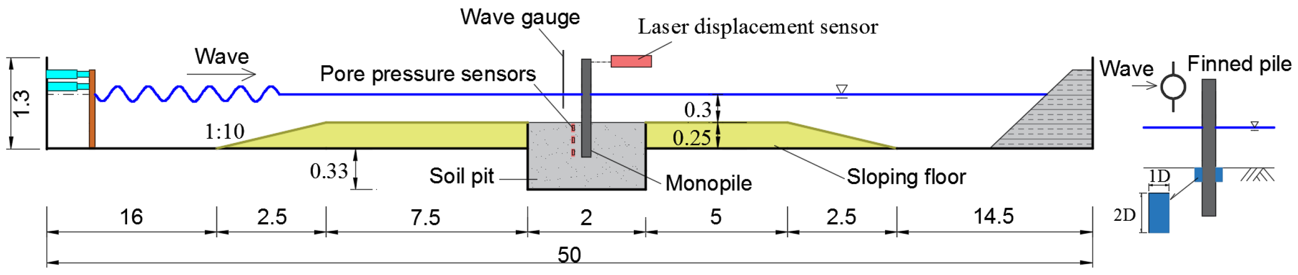
The wave flume at Hohai University was used; Figure 1 shows the experimental layout and Table 1 lists all the tests. The wave flume had a length of 50 m, a width of 1 m (perpendicular to the page) and a height of 1.3 m. Regular waves were generated from the propeller at the left end and porous material was used at the right end to absorb the wave, thus reducing the wave reflection. The wave generator of the propeller was capable of generating regular waves with a wave period of 0.6 s–2.5 s and a maximum wave height of 0.2 m. A soil pit with a depth of 0.33 m below the flume bottom was located in the middle of the flume. Two trapezoid-shaped blocks were placed on the flume floor adjacent to the pit [21], so the depth of the soil sample was extended to 0.58 m, which was sufficient to accommodate the pile foundation and sensors for the experiments. The length of the block was 7.5 m and 5 m with a 1:10 sloping ramp. Thus, the water depth was 0.3 m and the wave pattern could be appropriately controlled.
2.2. Soil and Model Piles
Two soil samples made from commercial silicon materials were adopted for testing. Sample 1 was fine sand mixed with particle sizes of 0.15 mm and 0.06 mm in a mass ratio of 3:1. Sample 2 was uniform silt with a particle size of 0.06 mm. No other particle sizes were adopted in the tests. The test soil beds were prepared by pluviation to achieve a targeted relative density (Dr) of 0.73 for Sample 1 seabed and 0.82 for Sample 2 seabed. The submerged unit weights of the two samples were γ’ = 7.3 kN/m3 and 11.5 kN/m3, respectively. The permeability coefficient of the two samples was determined by a constant-head-permeability test, which showed k = 1.88×10⁻³ cm/s and 4.32×10⁻⁵ cm/s for Sample 1 and Sample 2 seabed, respectively. Table 2 summarizes the properties of the soil samples.
Four closed-end model piles were fabricated as shown in Table 1 and as follows: (1) an up-straight pile made from a plexiglass tube (a frequently-used material in flume experiments [27]) with a thickness of 2 mm, an outer diameter of 30 mm and a length of 1 m; (2) a similar plexiglass pile with a 50 mm outer diameter; (3) a 30 mm outer-diameter plexiglass pile to which two fins were attached (0.2 cm in thickness, 3 cm in width and 6 cm in height), as shown in Figure 1; (4) an aluminum pile with a 30 mm diameter and a 2 mm thickness. The Young’s modulus of plexiglass and aluminum was found to be 4.4 GPa and 70.8 GPa, giving a bending rigidity EI = 76.25 N•m2 and 1.23 kN•m2. As shown in Figure 1, the piles were hoisted in the center of the pit during pluviation and their tip was kept at least 5.6 D (D = 50 mm) above the pit bottom to exclude the boundary effects on a laterally loaded pile [6]. The lateral distance from the piles to the pit side-wall was larger than 10 D to eliminate side effects [28,29].
Three non-dimensional numbers relative to flow characteristics in the wave–pile interaction problem [30] are (1) the Froude number, Fr = Um/(gD)1/2, which is the ratio of inertia force to gravitational force and represents the dynamic similarity; (2) the Keulegan–Carpenter number, KC = UmT/D, which controls the generation and development of a vortex around a pile and is related to the hydrodynamic force acting on the pile under wave motion; and (3) the Reynolds number, Re = UmD/υ, which is the ratio of inertia force to viscous force. Note that Um is the flow velocity, D is the pile diameter, T is the wave period and υ is the kinematic viscosity of water. Given all tests were conducted under normal gravity (1 g) conditions, the similarity of the Froude number was satisfied, so λFr =λUm /(λgλD)1/2 = 1, where λ represents the ratio of the parameters of the model to those of the prototype. Considering λg = 1, the following relationship should be maintained:
λUm = λD1/2,
Using the dimensional analysis method to consider the similarity of period T, it could be further rendered to
λT = λD / λUm = λD1/2
Therefore,
λKC = λUm λT / λD =1
The above analysis indicates that the KC number follows Froude’s law; this could also be satisfied during the flume experiments, meaning that the hydrodynamic force on the pile followed the principle. However, the viscosity force related to the Re number cannot be directly scaled to prototype. In the case of ocean wave with a free surface, the gravitational effect predominates. The effect of viscosity is generally small and can be neglected, which hardly affects the overall motion of fluid in a flume [31]. However, it is worth noting that low confining pressure in the seabed under normal gravity could lead to a fast progress of pile failure.
2.3. Data Acquisition
The miniature pressure sensors used (provided by Peneson; 6 mm in outer diameter and 20 mm in length) had a measurement range of 20 kPa with full-scale accuracy of ±0.1% and were installed along a vertical line at a distance of 1.5 D away from the pile axis and at depths of 0.05 m, 0.15 m and 0.25 m below the mudline. Pore-pressure signals were sampled and amplified through a signal-processing device (USB-2533) and DAQ-pro data acquisition software. The laser displacement sensor (optoNCDT1402-20; manufactured by Micro-Epsilon) used in the experiments had a measurement range of 20 mm, with a resolution of 0.002 mm and a maximum sampling rate of 1.5 kHz. The sampling locations for pile-head displacement were at the pile front and 20 mm below the pile top. Wave-height gauges, with a measurement range of 0.60 m and a measurement precision of 0.1 mm, were located along the central axis of the wave flume and in front of the piles. A remote computer was connected to the servo system and acquisition system to synchronously record the signals from the pore-pressure sensors, displacement sensors and wave-height gauges, using a typical sampling frequency of 50 Hz. All the sensors employed in the experiments were capable of providing adequate measured data to investigate pile–seabed interactions under wave loading.
2.4. Preparation and Testing
The testing procedure was as follows: (1) Three pore-pressure sensors (with their filters covered, to avoid particles entering) attached to a steel bar (diameter of 10 mm) were put to sit on the bottom of the pit. (2) The model pile was hoisted in the center of the pit during sand pluviation. (3) After the seabed (thickness of 0.58 m) had been formed, the water level was slowly adjusted to a height of 0.3 m above the bed surface. The soil sample and water level rested for 48 h to let the bed stabilize. (4) The wave generator was switched on according to the designed wave input and wave action was applied.
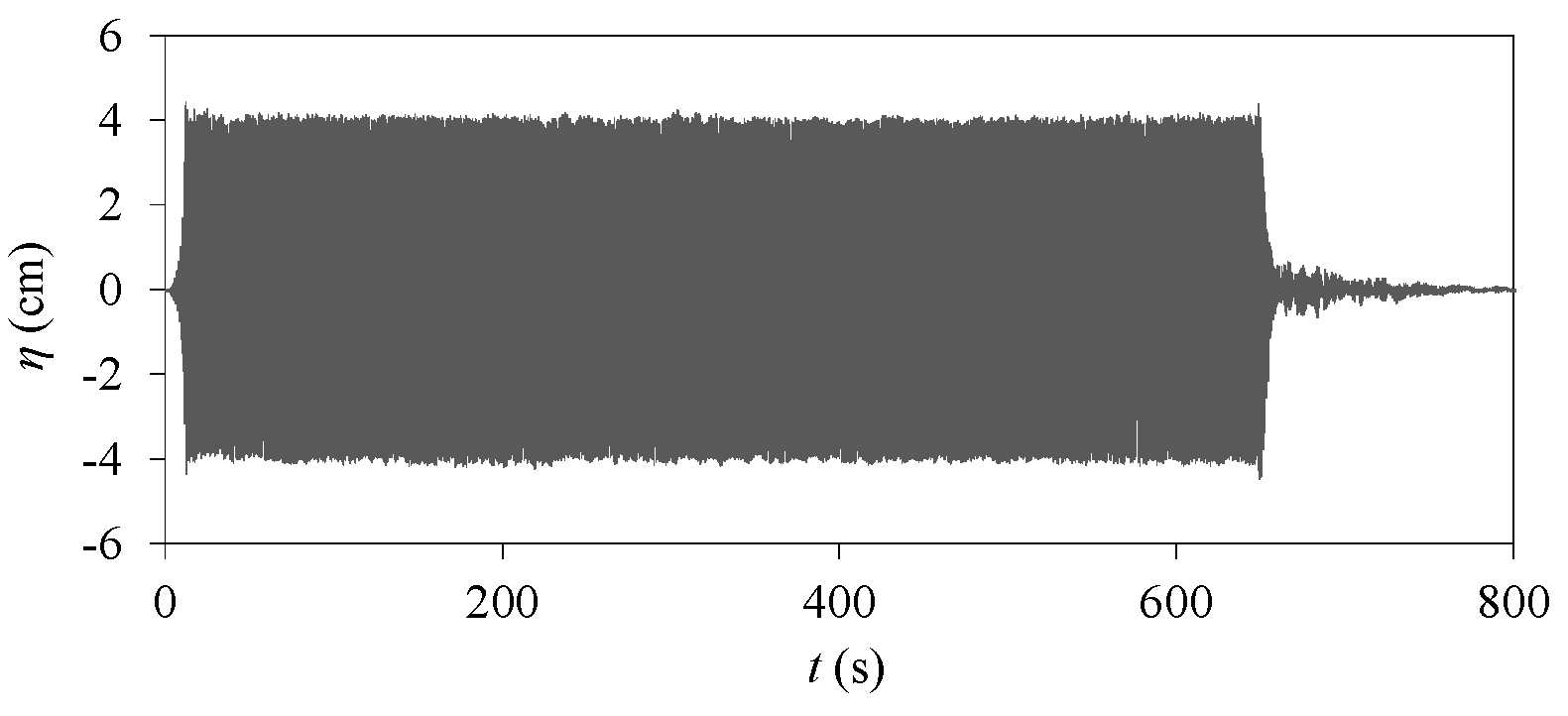
As shown in Table 1, regular waves were used with a period of 1 s and heights of 8 cm and 10 cm. Pore pressure and pile-head displacement were measured during 640 s of wave action. In T8(s-H8-D3p), a 200 s resting time was adopted before the second wave-loading stage. The 12 tests could be divided into two main groups according to Sample 1 and Sample 2 seabed, including the variation in pile diameter, pile cross-section, pile stiffness and wave height. Waves propagated in the flume with the same arrangement (Figure 1). Figure 2 shows the water-surface elevation (η) above the trapezoid-shaped blocks varying with loading time (t), H = 8 cm. Wave amplitude was uniform due to the incoming wave energy and wave reflection was dissipated well by the downstream wave absorber, indicating that the wave height selected in the tests was reasonable for the flume utilization and the resting time applied in the study was sufficient.
3. Testing Results
Among the 12 tests, T2(f-H8-D3p) and T8(s-H8-D3p) were the base tests including a plexiglass pile and seabed. T1(f-H8) and T7(s-H8) were pure seabed without any piles.
3.1. Responses of Sample 1 and Sample 2 Seabed
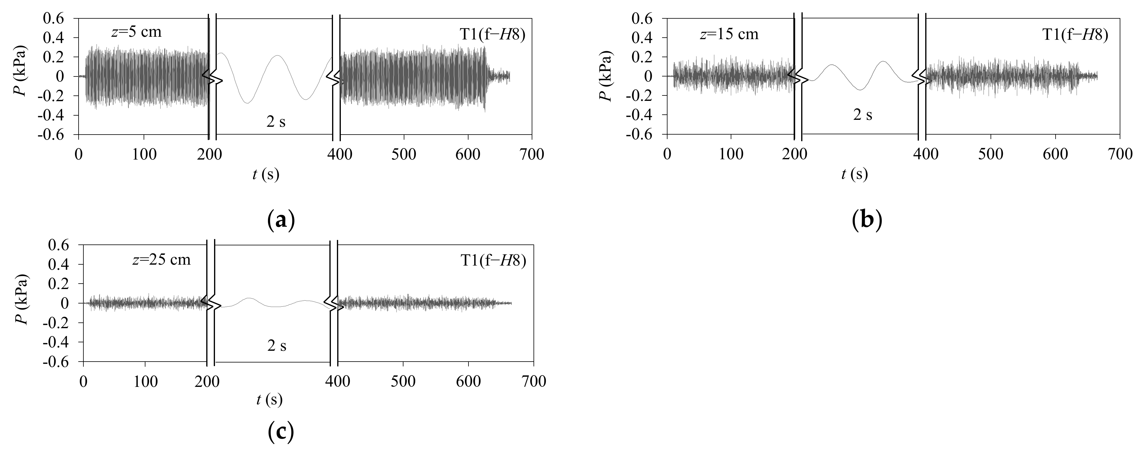
Figure 3 shows the pore pressure (P) recorded in T1(f-H8) in pure Sample 1 seabed (without any piles) during the wave action of 640 s; note that waves started at t= 10 s. The amplitude of pore pressure showed a value that was almost consistent with loading time, indicating that no substantial accumulation of pore pressure occurred. The pore-pressure amplitude decreased with seabed depth, as expected (see references [25,31]).
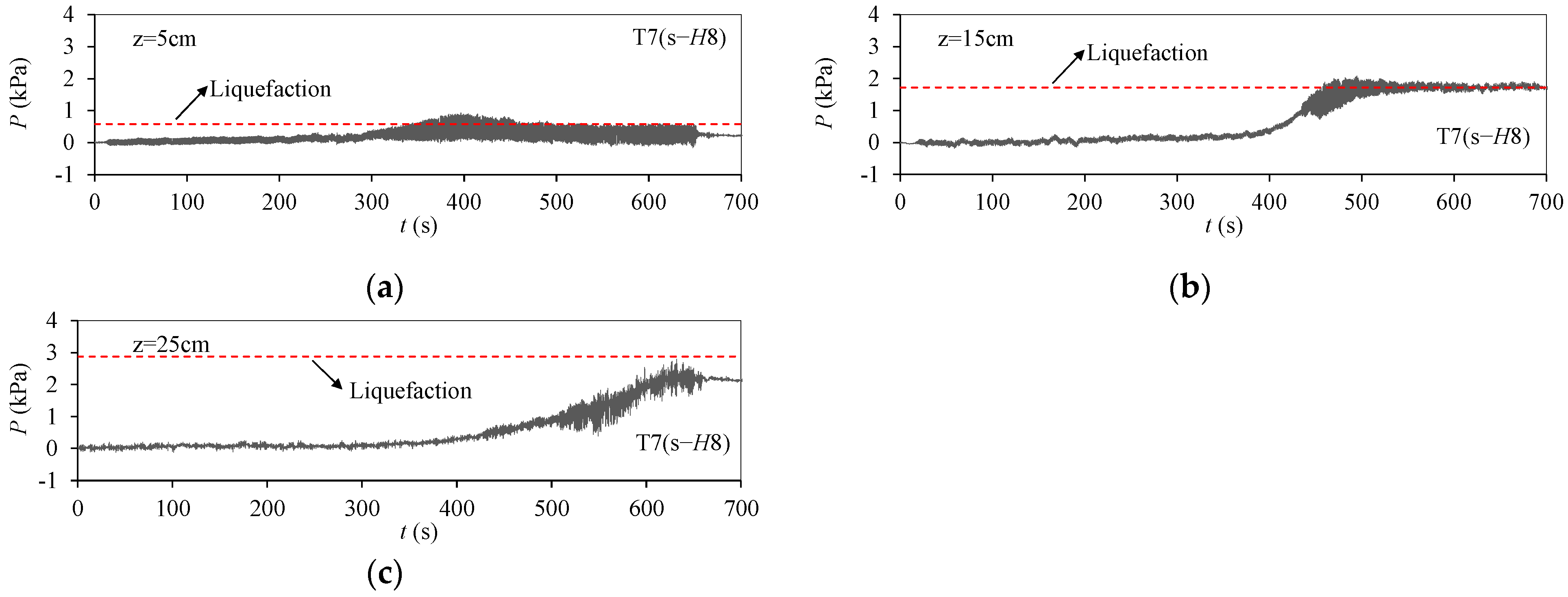
Figure 4 shows the development of pore pressure in T7(s-H8) in pure Sample 2 seabed. Different from T1(f-H8) with Sample 1 seabed, pore-pressure build-ups could be clearly observed after an earlier stable period and the beginning time varied from about 250 s to 400 s with depth. Then, the pore pressure in the upper seabed reached a peak value and that in the deep seabed kept increasing during wave loading. As soil liquefaction is defined as the residual pore pressure being equivalent to effective soil stress (see dashed line in Figure 4), the typical liquidated response of seabed could be found at depth z ≤ 15 cm. Unlike in Sample 1 seabed with two-order-higher permeability, the results measured in the silty seabed (Sample 2) displayed two properties. (1) The pore-pressure amplitude build-up increased significantly at each depth, e.g., increasing from nearly 0.1 kPa to 0.5 kPa at z = 5 cm and from 0.1 kPa to 0.8 kPa at z = 25 cm. (2) The accumulation of pore pressure was apparently related to depth and showed a higher value in the deep seabed, indicating the significant effect of soil permeability on seabed response.
3.2. Pore Pressure around Piles
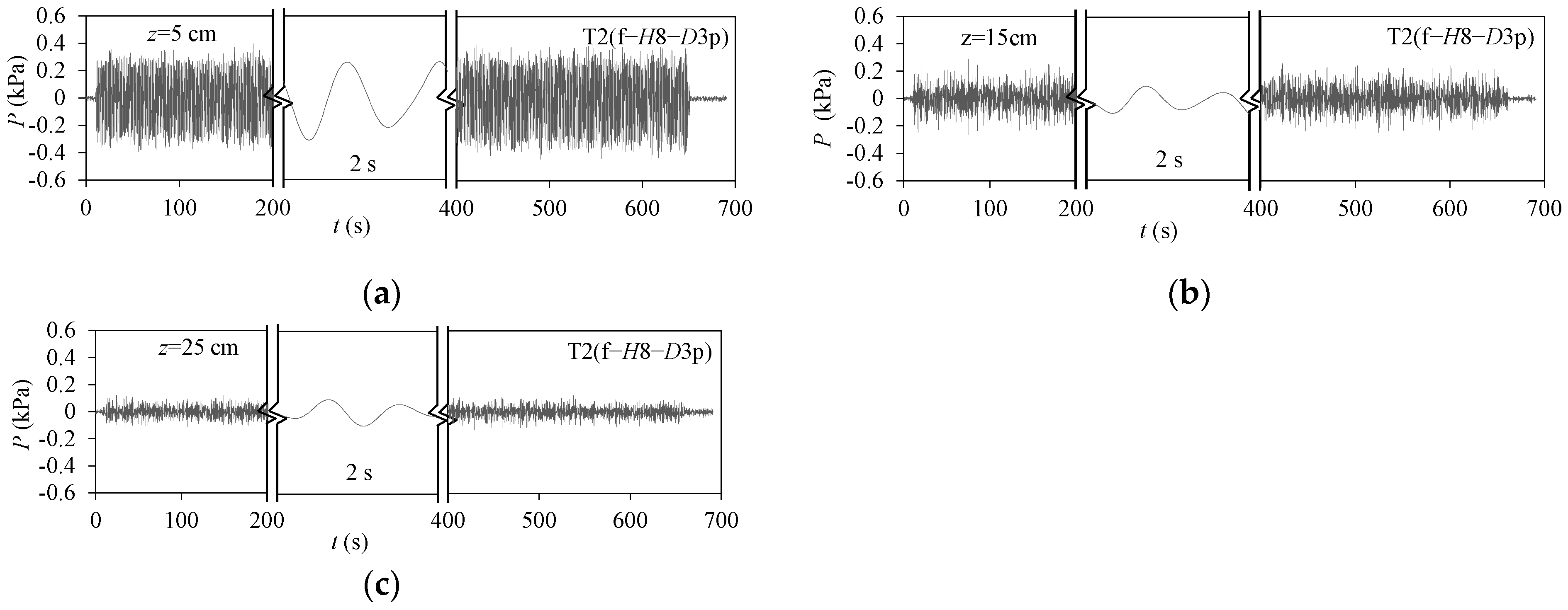
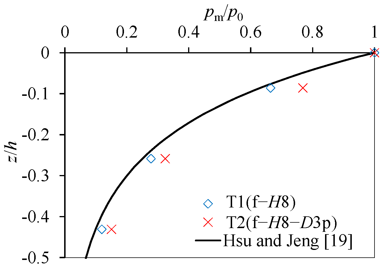
Figure 5 shows the response of pore pressure recorded in T2(f-H8-D3p) in Sample 1 seabed around a pile. A similar response of pore pressure with different amplitudes could be seen, showing a non-negligible effect of the pile on surrounding soil. Based on the measurements, Figure 6 illustrates the vertical distribution of the average amplitude of the pore pressure in Sample 1 seabed, where pm is the average amplitude of the pore pressure in the seabed and p0 is the amplitude of the dynamic water pressure on the seabed surface. Comparing with the result of T1(f-H8), pm around the pile increased by 15.7%, 16.5% and 25.9% at depths of 5 cm, 15 cm and 25 cm, respectively (see Figure 6), indicating that the effects of drained-path extension and surrounding-soil compression could be obvious in fine sandy seabed with a pile. Moreover, no evidence of residual pore pressure was observed because wave-induced pore pressure dissipated over time.
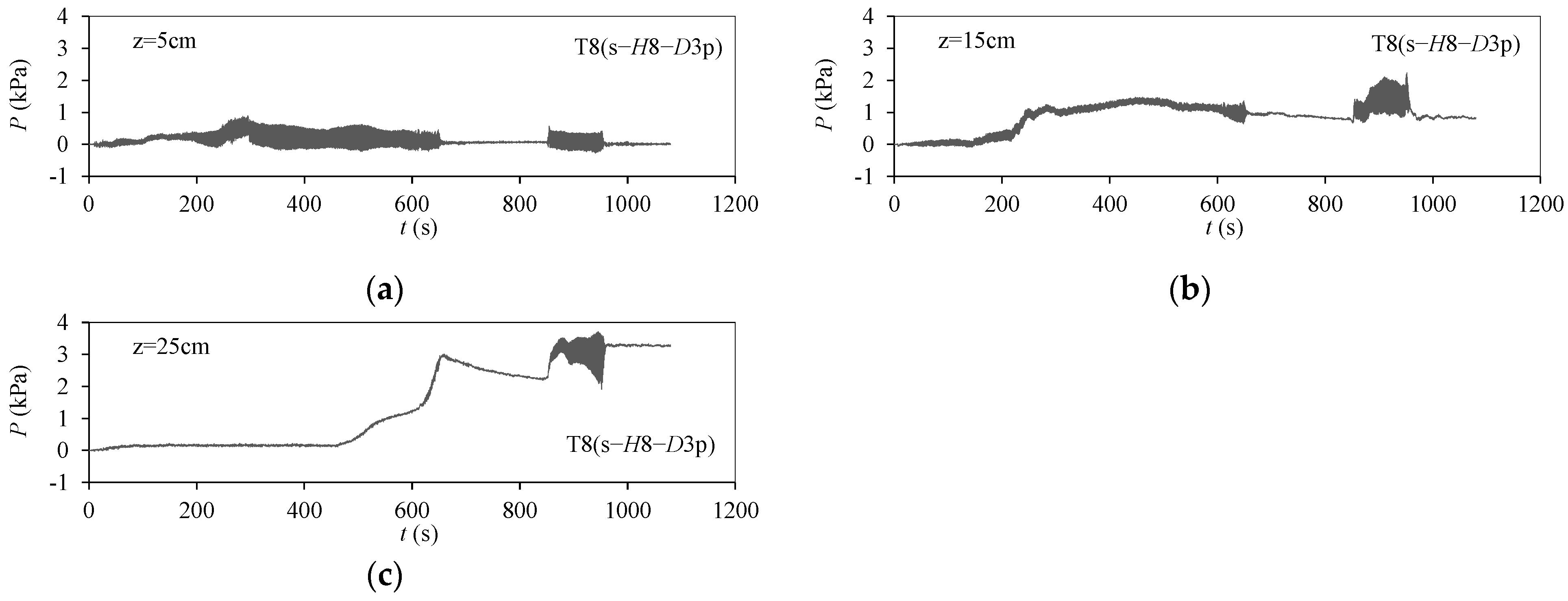
Similar to the responses of pure Sample 2 seabed (see T7(s-H8) in Figure 4), the pore pressure in the vicinity of the pile accumulated in T8(s-H8-D3p) in Sample 2 seabed, as shown in Figure 7. Further examination indicated that pore pressure increased more rapidly in T8(s-H8-D3p) than in T7(s-H8), which is associated with the early-liquefaction phenomenon. For example, the liquefaction that occurred at a depth of 15 cm (Figure 7b) occurred about 200 s earlier than that observed in T7(s-H8) (see Figure 4b). In the resting time between these two wave-action stages in T8(s-H8-D3p), pore pressure drained slowly and its decreased values were closely related to depth. Figure 7a,b also shows a sharp decrease after liquefaction at z = 5 cm and a remarkable increase during the first loading stage at z = 15 cm. An expected explanation was a seepage path forming in the liquefied seabed close to the pile, which released pore pressure and brought higher wave pressure to the deep seabed.
As mentioned in Figure 6, the mean value of the amplitudes of the pore pressure in Sample 1 seabed, pm, was much higher in shallow seabed because of shorter seepage paths, e.g., pm at z = 5 cm (z/h = 0.09) was 5.6 times that at z = 25 cm (z/h = 0.43). With respect to pore pressure varying with depth, Hsu and Jeng [19] suggested an analytical solution for wave-induced pore-pressure response, applicable to sandy seabed of finite thickness. The governing equations were deduced from Biot’s consolidation theory [20] and the amplitudes of pore pressure (|Δu|) normalized with those of dynamic-wave pressure at the seabed surface (p0), expressed as
where ν is Poisson’s ratio for the seabed. The other main parameters are
where n is the soil porosity; kx and kz are the soil permeability in the horizontal and vertical directions, respectively; γw is the water specific weight; G is the soil shear modulus; k is the wave number; ω is the wave frequency; Kw is the bulk modulus of water taken as 2×10⁹ N/m2; Sr is the degree of saturation; and pwo is the absolute pore pressure. The expressions for the six resulting coefficients, C1 – C6, were taken from Hsu and Jeng [19].
As shown in Figure 7, the experimental results agree well with the analytical solutions, in which the parameters involved were adopted as kx = kz = 1.88×10⁻³ cm/s, G = 3×10⁷ Pa, ν = 0.3, n = 0.53, Sr = 0.975 and Kw = 2×10⁹ Pa. It is noteworthy that pore pressure (p) in T2(f-H8-D3p) was comparatively larger, indicating an obvious promoting effect of the soil close to a pile on pore pressure. As a consequence of pile–soil interactions, the wave-induced pore pressure around a pile was difficult to estimate accurately using previous analytical methods.
3.3. Displacement of Piles
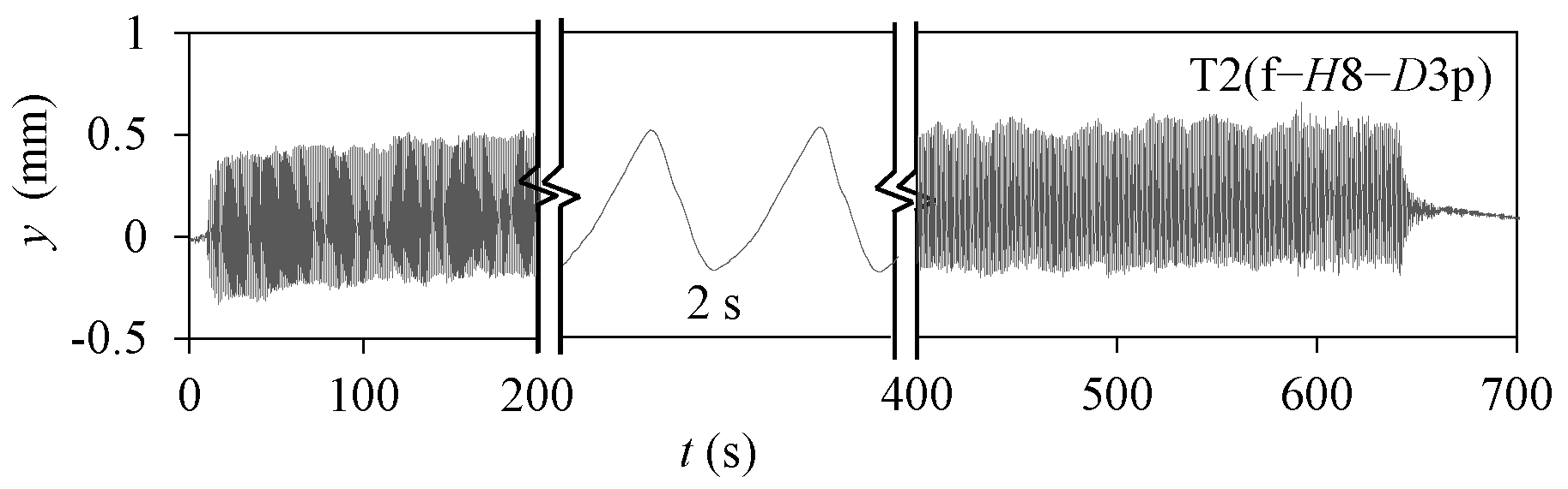
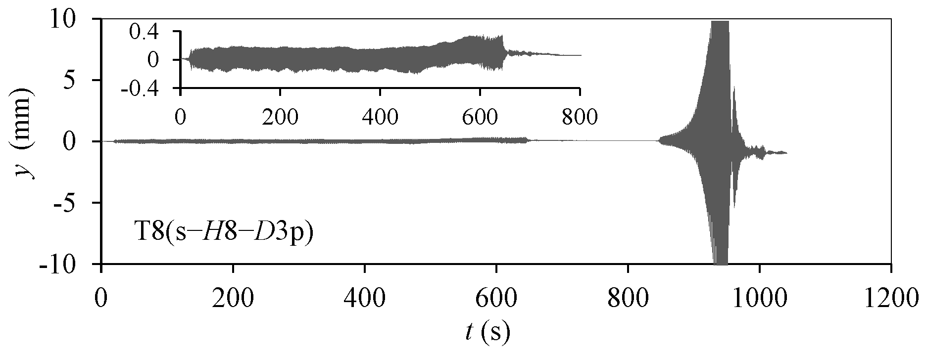
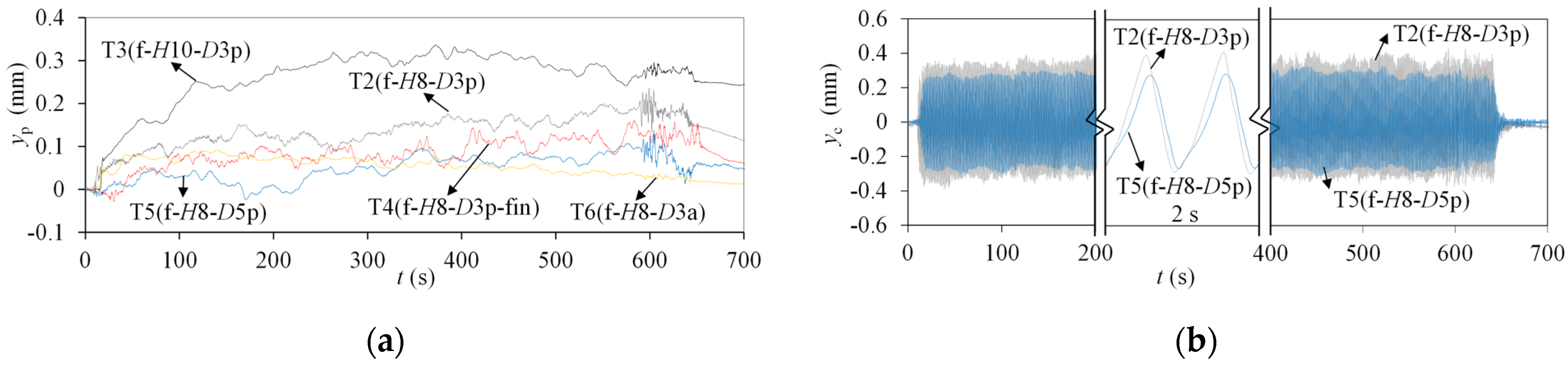
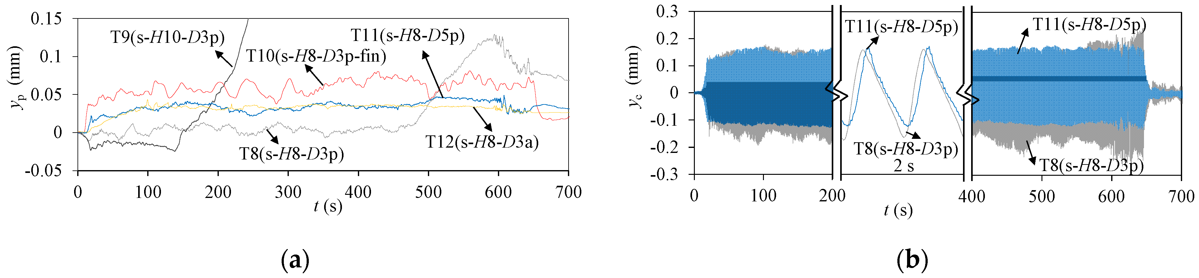
Figure 8 and Figure 9 show pile-head displacement in different seabed types under wave action. The response of the pile in Sample 1 seabed remained stable with loading time, although a small accumulation was observed in the overall trend of displacement development. By examining the pore pressure in Figure 5, it could be suggested that an increase in pore pressure did not firmly affect the pile response because of the high permeability of the seabed. In addition, the displacement response of the pile in Sample 2 seabed (small picture in Figure 9) was smaller than that recorded in Sample 1 seabed when they were in the first wave-loading stage. One explanation could be that Sample 2 seabed was prepared with a higher relative density of 0.82. Generally, denser soil is expected to provide higher lateral stiffness, which leads to lower pile response. Moreover, the pile behaved aggressively at the end of the first loading stage and quickly developed into the measured range at the beginning of the second loading stage in Figure 9. Obviously, continuous wave loading would accelerate pile failure in Sample 2 seabed due to pore-pressure accumulation. Referring to the pore-pressure graph for T8(s-H8-D3p) shown in Figure 6, the liquefaction that happened at z = 25 cm was a primary failure sign of the pile in Sample 2 seabed under wave loading; note that accumulated displacement started to grow progressively when the liquefaction depth was 15 cm.
4. Discussion of Wave-Induced Pile–Seabed Response
4.1. Pile-Diameter Effect
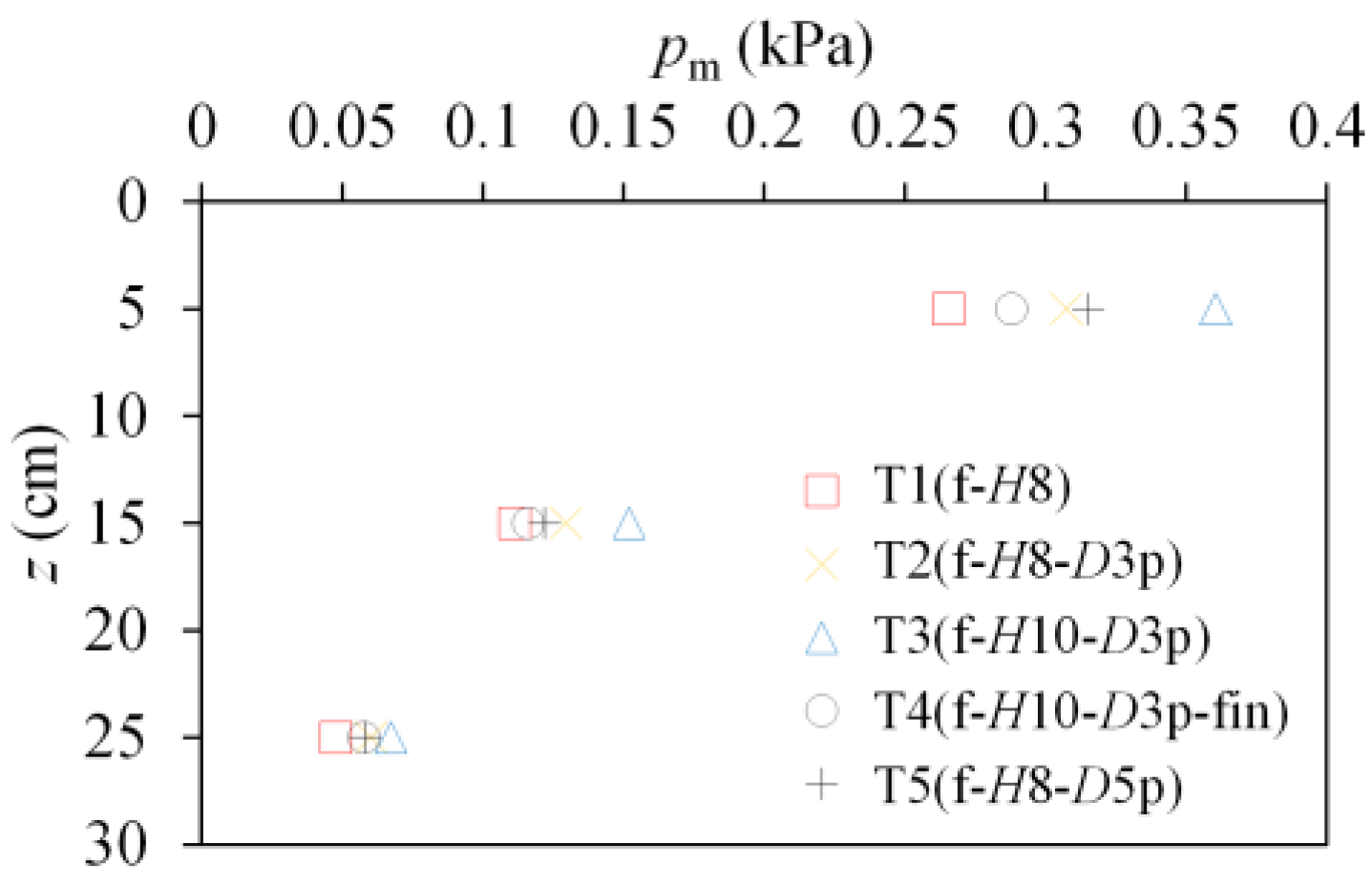
Figure 10 shows the average pore-pressure amplitudes, pm, varying with depth in the experiments with Sample 1 seabed. The value of pm for the piles with a 3 cm diameter in T2(f-H8-D3p) was close to the value for 5 cm diameter piles in T5(f-H8-D5p), especially as depth increased. This result indicates that the effect of diameter on pore-water dissipation was negligible, probably because of the high permeability of Sample 1, although previous studies have found that piles with larger diameters could be disadvantaged because of drainage boundary conditions.
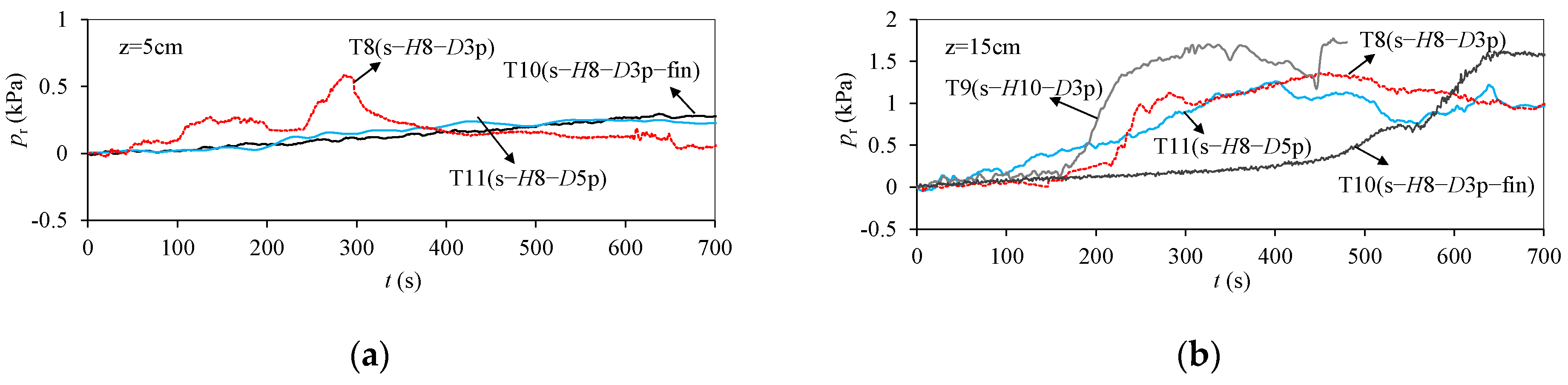
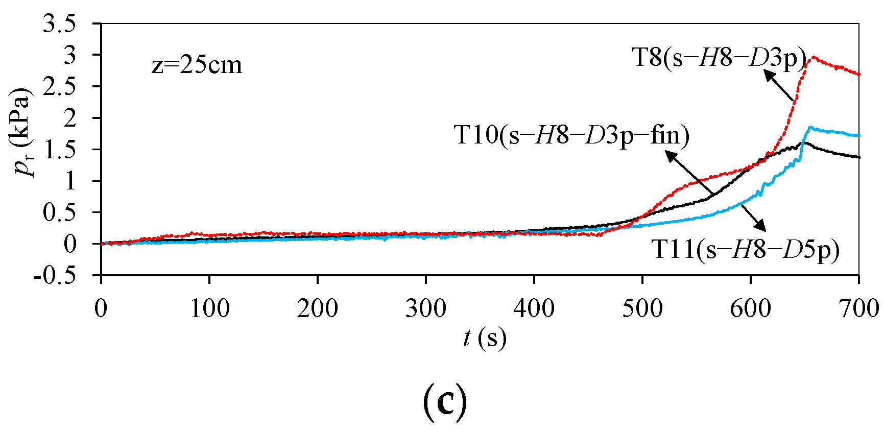
The pore pressure measured in pure Sample 2 seabed (see T7(s-H8) in Figure 4) comprises two temporal components, i.e., residual pore pressure pr and oscillating pore pressure po. Residual pore pressure can be derived by applying the linear-moving-average (LMAV) scheme, as suggested by Foda and Tzang [32]. Oscillating pore pressure is obtained by subtracting the residual component from the total pore pressure. Figure 11 presents the development of residual pore pressure close to the piles in Sample 2 seabed against wave-loading time. As the pile diameter increased from 3 cm (T8(s-H8-D3p)) to 5 cm (T11(s-H8-D5p)), the maximum pr decreased by 57.0%, 35.2% and 37.4%, with depth increasing from 5 cm to 25 cm. By inference from these results, it can be concluded that the contribution of pile displacement response to pore-pressure accumulation in Sample 2 seabed was greater than that of pile diameter. This deduction is further demonstrated in the following discussion.
Figure 12 and Figure 13 show the permanent components and cyclic components deduced from the pile-head-displacement values using the LMAV. Increases in pile diameter led to smaller permanent and cyclic components under 640 s of regular wave action in both Sample 1 and Sample 2 seabed, with curves shown in Figure 12 (T2(f-H8-D3p), T5(f-H8-D5p)) and Figure 13 (T8(s-H8-D3p), T11(s-H8-D5p)). From the results of the present experiments, a more stable state is expected for large-diameter piles under wave loading in Sample 2 seabed.
Although larger-diameter piles are subjected to enormous wave loads, an extra area of pile–seabed interaction also provides more lateral resistance, which limits pile displacement. Further work was conducted to explore the effect of pile diameter on pile displacement response. Wave length L in the tests was 1.55 m according to the linear wave theory, meaning that the maximum value of D/L was only 0.03. Hence, the wave load on the piles (Fw) could be calculated through the Morison equation (D/L ≤ 0.15) [33] as follows:
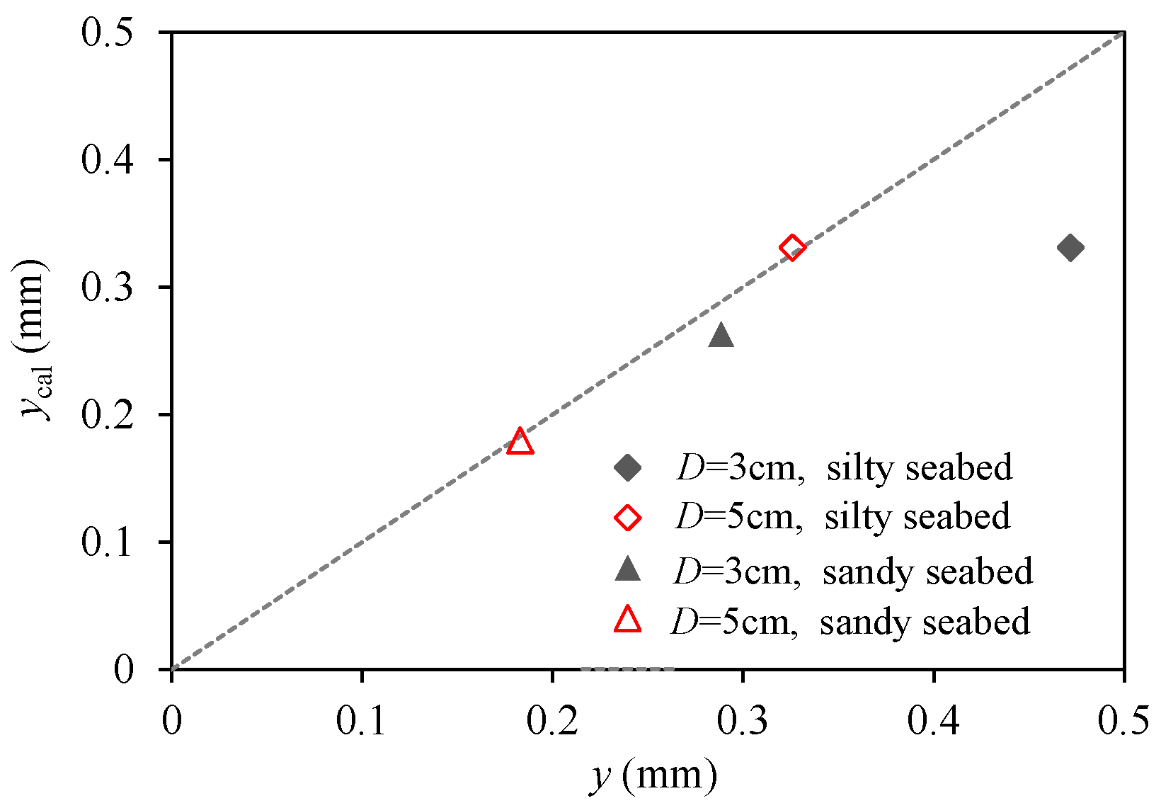
For simplification, the velocity of the piles was considered as zero, since the analysis here was mainly focused on small pile responses. It is worth noting that the horizontal acceleration of piles should be considered when pile displacement is large in actuality. CM and CD were given as 2 and 1.2, respectively. The third-order Stokes wave suggested by Le Méhauté [34] was used to calculate wave load Fw. The interaction between the pile and seabed was considered using the p–y curves suggested by API [12] for silt and by Reese et al. [4] for fine sand. Substituting the relative parameters into Equation (8) and combining the pile displacement analysis method, the calculated pile displacement ycal is shown in Figure 14, where y means the measured pile-head displacement.
Figure 14 indicates that the calculated and measured values of pile displacement increased with the decrease in pile diameter. By comparing the two, we could see that the calculated value agrees well with the measured value for the pile with a diameter of 5 cm. More-significant differences were found for the small-diameter pile. Larger pile responses were induced with the small-diameter pile and resulted in a strong compression effect on surrounding soil, leading to higher residual pore pressure and degenerating the lateral stiffness of the pile. However, these interactions could not be considered by the methods using the p–y curve, which led to errors. In other words, the effect of pore pressure induced by pile response was more significant than that induced by the increase in drainage path because of pile diameter; the traditional evaluation method of pile displacement is more applicable for piles with a large diameter or small pile response.
4.2. Pile-Cross-Section Effect
This paper also studied the effectiveness of fins attached to piles in different seabed types. The results of pore pressure in Sample 1 seabed with a finned pile can be seen in Figure 10. Compared with the results from T2(f-H8-D3p) with a normal pile, the application of fins in T4(f-H8-D3p-fin) led to a decline in pm by 6.4 %, 10.4 % and 4.1 % at z = 5 cm, 15 cm and 25 cm, respectively, which was especially significant at locations adjoining fin locations (see z = 15 cm in T4(f-H8-D3p-fin)). Fins contributed more lateral resistance by mobilizing more surrounding soil, along with small pile displacement and pore pressure.
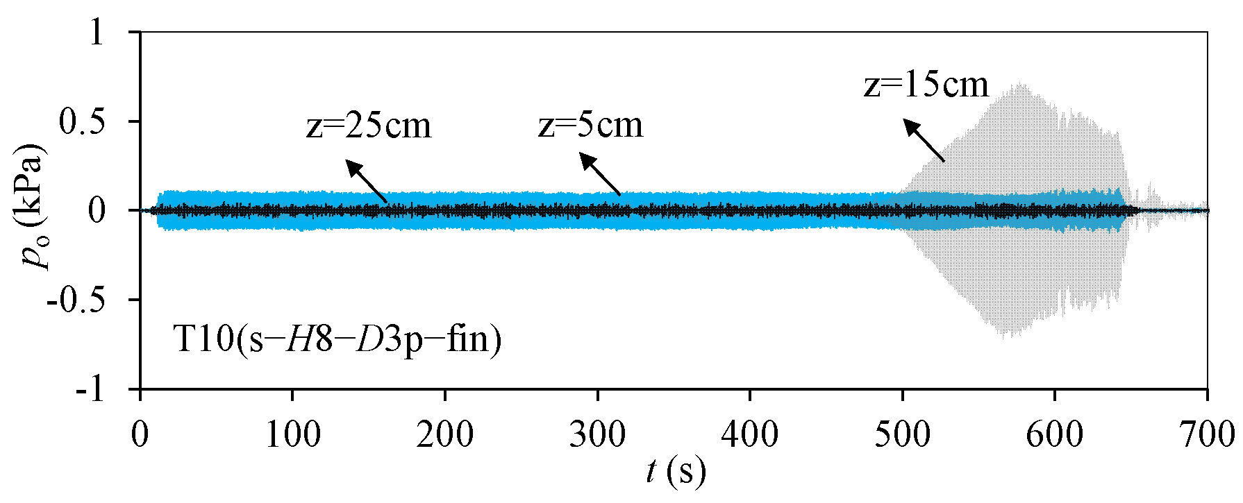
The effect of fins on the responses of pore pressure in Sample 2 seabed can be seen in Figure 11. As the depth increased from 5 cm to 25 cm, the residual pore pressure (pr) of the soil around the finned pile in T10(s-H8-D3p-fin) rose similarly to that around the normal pile in T8(s-H8-D3p), but its peak value was smaller, e.g., 45.6% lower at z = 25 cm in T10(s-H8-D3p-fin). Sample 2 seabed with higher relative density, which might be critical for fin application, allowed the fins to acquire more support from the subgrade and to stop surrounding soil from compacting. Figure 15 presents the oscillating pore pressure in T10(s-H8-D3p-fin) (po) decreasing with depth, especially in the stable response period, e.g., the mean values of amplitude at z = 5 cm were about four times those at z = 15 cm in the first 400 s and tended to rapidly develop with loading time when Sample 2 soil was close to liquefaction. Note that the amplitude of pr at z = 15 cm was even greater than the wave pressure at the seabed surface (see Figure 11b); this is because the constitution and structure of local soil had rebuilt and its particles had moved in response to periodic seepage. This alternation affected the permeability of the local seabed and resulted in a sharp secondary increase in pr.
The pile-head displacement of the finned pile in Sample 1 seabed (T4(f-H8-D3p-fin)) can be seen in Figure 12a. The permanent displacement of the finned pile developed much more slowly with a small peak value. Combined with the pore-pressure measurements, this result demonstrates that sufficient lateral resistance was mobilized by using fins and that the lateral stiffness of the pile in Sample 1 seabed was nearly unvaried.
Figure 13a gives the permanent displacement of the finned piles embedded in Sample 2 seabed (see T10(s-H8-D3p-fin)). Related to pore pressure, the reduction in lateral stiffness leading to poor efficiency of pile–seabed interactions was limited in Sample 2 seabed. Compared with normal piles, fin application is a very effective method for controlling pile response and sufficient lateral support from the seabed.
4.3. Pile-Stiffness Effect
Pile stiffness is another important factor in pile lateral-displacement response. Two materials, plexiglass and aluminum, were used to fabricate the model piles. The ratio of stiffness between these two piles reached 1:22 to facilitate the comparison. Regarding the permanent displacement shown in Figure 12a, the aluminum pile in T6(f-H8-D3a) in Sample 1 seabed presented the smallest responses, showing the noticeable effect of pile stiffness. Results similar to those obtained for Sample 2 seabed can be seen for the aluminum pile in T12(s-H8-D3a) (Figure 13a), where a small increment of permanent displacement was observed in the experiments. This was due to finite deflection being transmitted to the deep seabed, leading to small soil plastic strain and avoiding soil-strength degradation.
4.4. Wave-Height Effect
Greater water pressure was applied to the seabed surface as wave height increased from 8 cm in T2(f-H8-D3p) to 10 cm in T3(f-H10-D3p), as shown in Figure 10. The mean pore-pressure amplitudes (pm) increased by 12.1%–17.3%, which was the highest value among the experiments with Sample 1 seabed. Wave height seemed to have a major effect on the response of Sample 1 seabed.
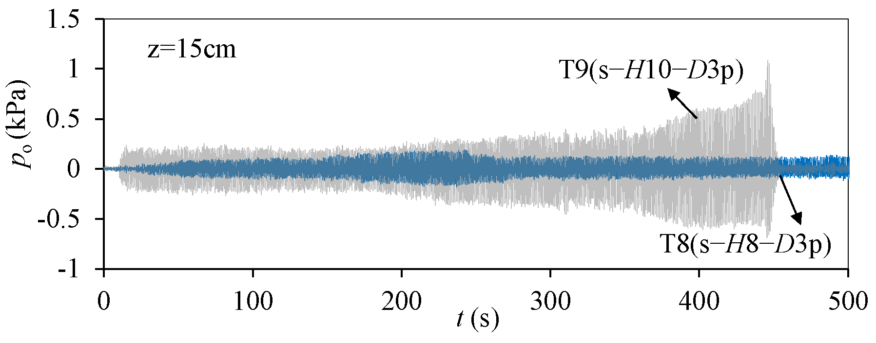
The effect of wave height on residual pore pressure in Sample 2 seabed can be found in Figure 11b. An earlier rapid accumulation process of pore pressure was observed with higher wave height in T9(s-H10-D3p) and with an unstable response state containing a descent period. The corresponding oscillating pore pressure values obtained from T8(s-H8-D3p) and T9(s-H10-D3p) are presented in Figure 16, showing that the oscillating pore pressure at z = 15 cm was high for H = 10 cm, including its increments. It is worth noting that the rapid ascending period of po in T9(s-H10-D3p) in Figure 16 corresponds to the descending period in Figure 11b, indicating that drastic fluctuations in oscillating pore pressure induced soil particles to form transient drained paths at that time. Moments later, these paths were closed, which resulted in another ascending period of residual pore pressure in T9(s-H10-D3p), as shown in Figure 11b.
Figure 12a also presents the permanent displacement of piles in Sample 1 seabed under different wave loadings (T2(f-H8-D3p) and T3(f-H10-D3p)). Due to slight residual pore pressure induced by 10 cm high waves (Figure 10), a relatively gentle curve of yp was observed in T3(f-H10-D3p). The main source of accumulated displacement was the finite plastic strain of surrounding soil induced by the cyclic response of the pile.
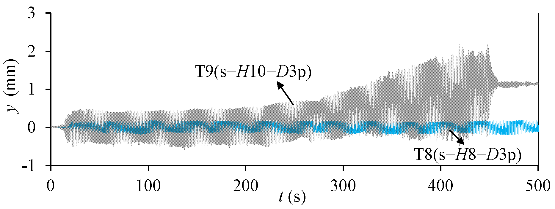
The permanent displacement of piles under 10 cm high waves in Sample 2 seabed is shown in Figure 13a, notated as T9(s-H10-D3p), showing a faster development than that subjected to 8 cm high wave action (T8(s-H8-D3p)). Apparently, the rise in residual pore pressure accelerated the pile response, which can also be verified by examining the total displacement of the pile presented in Figure 17. When pr in T9(s-H10-D3p) (Figure 13a) reached a high level, the cyclic displacement gradually magnified and caused a fast progress to pile failure. In conclusion, wave height was the major factor in the responses of piles and seabed according to the experiments; note that the confining pressure around the piles was low when compared to prototype, so the failure process should be partly accelerated.
5. Conclusions
This paper presents the results from wave-flume experiments exploring the response of pile–seabed systems under regular wave action and discusses the effect of pile diameter, pile cross-section, pile stiffness and wave height. From the results of the experiments, the following conclusions can be drawn:
1. During 640 s of regular wave loading, the pore pressure in Sample 1 fine sandy seabed varied slightly and its amplitude decreased with the increase in depth. The prior analytical method for predicting pore pressure agreed well with the measured values but led to a relatively large error for the fine sandy seabed embedded with piles. Around a pile, pore pressure increased by 15.7%–25.9% at different depths.
2. In Sample 2 silty seabed, pore pressure gradually built up with wave action and reached higher values at deep locations. A rapidly increasing period of pore pressure around the piles appeared earlier than in pure silty seabed. Pile failure occurred soon, with liquefaction occurring at z = 15 cm (half the embedment) and being accompanied by higher oscillating pore pressure.
3. As the pile diameter increased from 3 cm to 5 cm, residual pore pressure decreased by 57.0%, 35.2 % and 37.4 % with depths increasing from 5 cm to 25 cm in silty seabed. By comparing the calculated value to the measured value, it was found that the displacement response of small-diameter piles was more possibly enlarged by the induced pore pressure.
4. Compared with normal piles, the use of fins led to a decrease in pore-pressure amplitude by 4.1%–10.4% in fine sandy seabed and the decrease in residual pore pressure was also apparent in silty seabed. The permanent displacement of the finned piles developed much more slowly and reached low peak values in both seabed types.
5. Wave height was a major factor in the responses of piles and seabed. As wave height increased from 8 cm to 10 cm, pore pressure increased by 12.1%–17.3% in fine sandy seabed and rapid stage of displacement accumulation was apparent in silty seabed.
Author Contributions
Conceptualization, T.H. and Y.T.; methodology, T.H.; software, T.H.; validation, T.H., Y.T. and G.D.; formal analysis, T.H.; investigation, G.D.; resources, G.D.; data curation, A.J.; writing—original draft preparation, T.H.; writing—review and editing, Y.T. and G.D.; visualization, Y.T.; supervision, G.D.; project administration, G.D.; funding acquisition, T.H. All authors have read and agreed to the published version of the manuscript.
Funding
This paper was financially supported by Fundamental Research Funds for the Central Universities (B200202050), China Communications Construction Company (2018-ZJKJ-01) and National Natural Science Foundation of China (No.51408185).
Institutional Review Board Statement
Not applicable.
Informed Consent Statement
Not applicable.
Data Availability Statement
Some or all data, models, or code that support the findings of this study are available from the corresponding author upon reasonable request.
Conflicts of Interest
The authors declare no conflict of interest.
References
- Pineda, I.; Tardieu, P. The European Offshore Wind Industry—Key Trends and Statistics 2016; Wind Europe: Brussels, Belgium, 2017. [Google Scholar]
- Golightly, C. Tilting of Monopiles: Long, Heavy and Stiff; Pushed beyond Their Limits. Ground Eng. 2014, 1, 20–23. [Google Scholar]
- DNVGL-st-0126; Support Structures for Wind Turbines, Offshore Standard. DNV: Oslo, Norway, 2016.
- Reese, L.C.; Cox, W.R.; Koop, F.D. Analysis of Laterally Loaded Piles in Sand. In Proceedings of the 6th Offshore Technology Conference, Houston, TX, USA, 5 May 1974; pp. 473–483. [Google Scholar]
- Murchison, J.; O’Neill, M. Evaluation of p-y Relationships in Cohesionless Soils. In Proceedings of the Analysis and Design of Pile Foundations, San Francisco, CA, USA, 1–5 October 1984; pp. 174–191. [Google Scholar]
- Leblanc, C.; Houlsby, T.; Byrne, W. Response of Stiff Piles in Sand to Long-Term Cyclic Lateral Loading. Géotechnique 2010, 60, 79–90. [Google Scholar] [CrossRef]
- Truong, P.; Lehane, B.M.; Zania, V.; Klinkvort, R.T. Empirical Approach based on Centrifuge Testing for Cyclic Deformations of Laterally Loaded Piles in Sand. Géotechnique 2019, 69, 133–145. [Google Scholar] [CrossRef]
- Bienen, B.; Dührkop, J.; Grabe, J.; Randolph, M.F.; White, D.J. Response of Piles with Wings to Monotonic and Cyclic Lateral Loading in Sand. J. Geotech. Geoenviron. 2012, 138, 364–375. [Google Scholar] [CrossRef]
- Kuo, Y.S.; Achmus, M.; Abdel-Rahman, K. Minimum Embedded Length of Cyclic Horizontally Loaded Monopiles. J. Geotech. Geoenviron. 2012, 138, 357–363. [Google Scholar] [CrossRef]
- Albiker, J.; Achmus, M.; Frick, D. 1 g Model tests on the Displacement Accumulation of Large Diameter Piles under Cyclic Lateral Loading. Geotech. Test. J. 2017, 40, GTJ20160102. [Google Scholar] [CrossRef]
- Bhattacharya, S.; Carrington, T.M.; Aldridge, T.R. Design of FPSO Piles against Storm Loading. In Proceedings of the OTC, Houston, TX, USA, 1–4 May 2006. OTC 17861. [Google Scholar]
- API (American Petroleum Institute). Geotechnical and Foundation Design Considerations, API Recommended Practice 2GEO, 1st ed.; API: Washington, DC, USA, 2011. [Google Scholar]
- Klinkvort, R.T.; Leth, C.T.; Hededal, O. Centrifuge Modelling of a Laterally Cyclic Loaded Pile. In Proceedings of the 7th International Conference on Physical Modelling in Geotechnics, Zurich, Switzerland, 28 June–1 July 2010; pp. 959–964. [Google Scholar]
- Haigh, S.K. Foundations for Offshore Wind Turbines. In Proceedings of the 8th International Conference on Physical Modelling in Geotechnics 2014, Perth, Australia, 14–17 January 2014; pp. 153–159. [Google Scholar]
- Nicolai, G.; Ibsen, L.B.; O’Loughlin, C.D.; White, D.J. Quantifying the Increase in Lateral Capacity of Monopiles in Sand due to Cyclic Loading. Geotech. Lett. 2017, 7, 245–252. [Google Scholar] [CrossRef]
- Huang, T.; Bai, S.Y.; Hou, L.J.; Guo, Z.Y. The Effect of Wave Action on the Lateral Pile-Soil Interaction for Monopiles in Sandy Seabed. In Proceedings of the 28th ISOPE, Sapporo, Japan, 10–15 June 2018; pp. 488–492. [Google Scholar]
- Madsen, O.S. Wave-induced Pore Pressure and Effective Stresses in a Porous Bed. Géotechnique 2015, 28, 377–393. [Google Scholar] [CrossRef]
- Mei, C.C.; Foda, M.A. Wave-induced Responses in a Fluid-filled Poro-elastic Solid with a Free Surface-A Boundary Layer Theory. Geophys. J. R. Astronom. Soc. 2010, 66, 597–631. [Google Scholar] [CrossRef]
- Hsu, J.R.C.; Jeng, D.S. Wave-induced Soil Response in an Unsaturated Anisotropic Seabed of Finite Thickness. Int. J. Rock Mech. Min. Sci. Geomech. Abstr. 1994, 18, 785–807. [Google Scholar] [CrossRef]
- Biot, M.A. Theory of Elasticity and Consolidation for a Porous Anisotropic Solid. J. Appl. Phys. 1956, 26, 182–185. [Google Scholar] [CrossRef]
- Tzang, S.Y.; Ou, S.H. Laboratory Flume Studies on Monochromatic Wave-Fine Sandy Bed Interactions: Part 1 Soil Fluidization. Coast. Eng. 2006, 53, 965–982. [Google Scholar] [CrossRef]
- Kirca, V.S.O.; Sumer, B.M.; Fredsøe, J. Influence of Clay Content on Wave-Induced Liquefaction. J. Waterw. Port. Coast. Ocean. Eng. 2014, 140, 04014024. [Google Scholar] [CrossRef]
- Liu, B.; Jeng, D.S.; Ye, G.L.; Yang, B. Laboratory Study for Pore Pressures in Sandy Deposit under Wave Loading. Ocean. Eng. 2015, 106, 207–219. [Google Scholar] [CrossRef]
- Zhang, J.S.; Li, Q.Z.; Ding, C.; Zheng, J.H.; Zhang, T.T. Experimental Investigation of Wave-Driven Pore-Water Pressure and Wave Attenuation in a Sandy Seabed. Adv. Mech. Eng. 2016, 8, 1687814016651207. [Google Scholar] [CrossRef] [Green Version]
- Zhang, Q.; Zhai, H.; Wang, P.; Wang, S.; Chen, L.; Duan, L.; Liu, Y.; Jeng, D.S. Experimental Study for Wave-Induced Pore-Water Pressures in a Porous Seabed around a Mono-pile. Appl. Ocean. Res. 2020, 95, 102041. [Google Scholar] [CrossRef]
- Qi, W.G.; Li, Y.X.; Xu, K.; Gao, F.P. Physical Modelling of Local Scour at Twin Piles under Combined Waves and Current. Coast. Eng. 2019, 143, 63–75. [Google Scholar] [CrossRef] [Green Version]
- Bi, C.W.; Wu, G.Y.; Zhao, S.X.; Dong, G.H. Laboratory Experimental Investigation on the Hydrodynamic Responses of an Extra-Large Electrical Platform in Wave and Storm Conditions. Water 2019, 11, 2024. [Google Scholar]
- Nogami, T.; Novak, M. Resistance of Soil to a Horizontally Vibrating Pile. Earthq. Eng. Struct. D 1977, 5, 249–261. [Google Scholar] [CrossRef]
- Li, L.J.; Zheng, J.H.; Peng, Y.X.; Zhang, J.S.; Wu, X.G. Numerical Investigation of Flow Motion and Performance of a Horizontal Axis Tidal Turbine Subjected to a Steady Current. China Ocean. Eng. 2015, 29, 209–222. [Google Scholar] [CrossRef]
- Gao, F.P.; Gu, X.; Jeng, D.S. Physical Modeling of Untrenched Submarine Pipeline Instability. Ocean. Eng. 2003, 30, 1283–1304. [Google Scholar] [CrossRef]
- Sun, K.; Zhang, J.S.; Guo, Y.; Jeng, D.S.; Guo, Y.K.; Liang, Z.D. Laboratory Experimental Study of Ocean Waves Propagating over a Partially Buried Pipeline in a Trench Layer. Ocean. Eng. 2019, 173, 617–627. [Google Scholar] [CrossRef] [Green Version]
- Foda, M.A.; Tzang, S.Y. Resonant Fluidization of Silty Soil by Water Waves. J. Geophys. Res. 1994, 99, 20463–20475. [Google Scholar] [CrossRef]
- Morison, J.R.; Johnson, J.W.; Schaaf, S.A. The Force Exerted by Surface Waves on Piles. J. Petrol. Technol. 1950, 2, 149–154. [Google Scholar] [CrossRef]
- Le Méhauté, B. An Introduction to Hydrodynamics and Water Waves; Springer: Berlin/Heidelberg, Germany, 1976. [Google Scholar]
Figure 1.
Layout of the wave flume (unit: meter).

Figure 2.
Water-surface elevation.

Figure 3.
Pore pressure in pure Sample 1 seabed: (a) z = 5 cm; (b) z = 15 cm; (c) z = 25 cm.

Figure 4.
Pore pressure in pure Sample 2 seabed: (a) z = 5 cm; (b) z = 15 cm; (c) z = 25 cm.

Figure 5.
Pore pressure around a pile in Sample 1 seabed: (a) z = 5 cm; (b) z = 15 cm; (c) z = 25 cm.
Figure 5.
Pore pressure around a pile in Sample 1 seabed: (a) z = 5 cm; (b) z = 15 cm; (c) z = 25 cm.

Figure 6.
Measured values and analytical solutions in Sample 1 seabed. Solid line represents data taken form reference [19].
Figure 6.
Measured values and analytical solutions in Sample 1 seabed. Solid line represents data taken form reference [19].

Figure 7.
Pore pressure around a pile in Sample 2 seabed: (a) z = 5 cm; (b) z = 15 cm; (c) z = 25 cm.
Figure 7.
Pore pressure around a pile in Sample 2 seabed: (a) z = 5 cm; (b) z = 15 cm; (c) z = 25 cm.

Figure 8.
Pile-head displacement in Sample 1 seabed.

Figure 9.
Pile-head displacement in Sample 2 seabed.

Figure 10.
Averages of pore-pressure amplitudes in Sample 1 seabed.

Figure 11.
Residual pore pressure in Sample 2 seabed: (a) z = 5 cm; (b) z = 15 cm; (c) z = 25 cm.


Figure 12.
Displacement components in Sample 1 seabed experiments: (a) permanent component; (b) cyclic component.
Figure 12.
Displacement components in Sample 1 seabed experiments: (a) permanent component; (b) cyclic component.

Figure 13.
Displacement components in Sample 2 seabed experiments: (a) permanent component; (b) cyclic component.
Figure 13.
Displacement components in Sample 2 seabed experiments: (a) permanent component; (b) cyclic component.

Figure 14.
The calculated and measured pile displacement.

Figure 15.
Oscillating pore pressure around a finned pile in Sample 2 seabed.

Figure 16.
Oscillating pore pressure in Sample 2 seabed under different wave actions.

Figure 17.
Pile-head displacement in Sample 2 seabed under different wave actions.


Table 1.
Experimental conditions.
| Test No. | Related Model | Soil Type | Pile Material | Pile Diameter D (cm) | Wave Height H (cm) | Loading Time t (s) |
|---|---|---|---|---|---|---|
| T1(f-H8) | Seabed | Sample 1, fine sand | - | - | 8 | 640 |
| T2(f-H8-D3p) | Seabed and monopile | Sample 1, fine sand | Plexiglass | 3 | 8 | 640 |
| T3(f-H10-D3p) | Seabed and monopile | Sample 1, fine sand | Plexiglass | 3 | 10 | 640 |
| T4(f-H8-D3p-fin) | Seabed and finned pile | Sample 1, fine sand | Plexiglass | 3 | 8 | 640 |
| T5(f-H8-D5p) | Seabed and monopile | Sample 1, fine sand | Plexiglass | 5 | 8 | 640 |
| T6(f-H8-D3a) | Seabed and monopile | Sample 1, fine sand | Aluminum | 3 | 8 | 640 |
| T7(s-H8) | Seabed | Sample 2, silt | - | - | 8 | 640 |
| T8(s-H8-D3p) | Seabed and monopile | Sample 2, silt | Plexiglass | 3 | 8 | 760 |
| T9(s-H10-D3p) | Seabed and monopile | Sample 2, silt | Plexiglass | 3 | 10 | 640 (440) |
| T10(s-H8-D3p-fin) | Seabed and finned pile | Sample 2, silt | Plexiglass | 3 | 8 | 640 |
| T11(s-H8-D5p) | Seabed and monopile | Sample 2, silt | Plexiglass | 5 | 8 | 640 |
| T12(s-H8-D3a) | Seabed and monopile | Sample 2, silt | Aluminum | 3 | 8 | 640 |
Table 2.
Soil properties.
| Property | Sample 1, Fine Sand | Sample 2, Silt |
|---|---|---|
| Particle size, d50 | 0.15 mm | 0.06 mm |
| Minimum void ratio, emin | 0.856 | 0.833 |
| Maximum void ratio, emax | 0.411 | 0.412 |
| Selected void ratio, e | 0.53 | 0.49 |
| Friction angle, ϕ | 34.0° | 32.1° |
Publisher’s Note: MDPI stays neutral with regard to jurisdictional claims in published maps and institutional affiliations. |
© 2022 by the authors. Licensee MDPI, Basel, Switzerland. This article is an open access article distributed under the terms and conditions of the Creative Commons Attribution (CC BY) license (https://creativecommons.org/licenses/by/4.0/).
Share and Cite
MDPI and ACS Style
Huang, T.; Tian, Y.; Dai, G.; Jiao, A. Experimental Study of Wave-Induced Response of Piles in Seabed with Various Permeability. Appl. Sci. 2022, 12, 2698. https://0-doi-org.brum.beds.ac.uk/10.3390/app12052698
AMA Style
Huang T, Tian Y, Dai G, Jiao A. Experimental Study of Wave-Induced Response of Piles in Seabed with Various Permeability. Applied Sciences. 2022; 12(5):2698. https://0-doi-org.brum.beds.ac.uk/10.3390/app12052698
Chicago/Turabian StyleHuang, Ting, Yinghui Tian, Guoliang Dai, and Ao Jiao. 2022. "Experimental Study of Wave-Induced Response of Piles in Seabed with Various Permeability" Applied Sciences 12, no. 5: 2698. https://0-doi-org.brum.beds.ac.uk/10.3390/app12052698
Note that from the first issue of 2016, this journal uses article numbers instead of page numbers. See further details here.