
Axial Bearing Mechanism of Post-Grouted Piles in Calcareous Sand


1
Department of Underground Engineering, College of Transportation Engineering, Nanjing Tech University, Nanjing 211816, China
2
School of Civil Engineering, Southeast University, Nanjing 211189, China
*
Authors to whom correspondence should be addressed.
Appl. Sci. 2022, 12(5), 2731; https://0-doi-org.brum.beds.ac.uk/10.3390/app12052731
Submission received: 26 January 2022
/
Revised: 24 February 2022
/
Accepted: 2 March 2022
/
Published: 7 March 2022
(This article belongs to the Special Issue Recent Progress on Advanced Foundation Engineering)
Abstract
:Post-grouted piles, as a foundation form for large-span and large-scale structures on calcareous sand, are expected to provide a high bearing capacity, but research on the response of post-grouted piles subjected to axial load in calcareous sand is still in the exploratory stage. In this paper, a model test is constructed for static pressure piles in calcareous sand under axial loading. The response of axial compressive piles, with and without post-grouting, in calcareous sand were investigated, and the test results were compared with those of axial compressive piles, with and without post-grouting, in siliceous sand. The influence of post-side-grouting on the response of a single pile subjected to axial compressive load in calcareous sand and its bearing mechanism were further analyzed. The results show that the change in shaft resistance, caused by the lateral extrusion of calcareous sand, is less than the negative effect caused by particle breakage during pile driving, so single piles without post-grouting in calcareous sand exhibit weaker axial bearing behavior than that in siliceous sand. A single pile with post-side-grouting in calcareous sand can provide a higher bearing capacity by increasing the shaft resistance and tip resistance compared with a single pile without post-side-grouting, and the increased ratio of the bearing capacity of piles, after grouting in calcareous sand, is better than that of piles in siliceous sand. Post-side-grouting can not only strengthen the surrounding soil by the solidification effect of injected cement grout, but it can also have a strengthening effect on the tip resistance. In addition, ideal-geometry grouting has more obvious advantages in improving the bearing behavior of pile foundations than annular point grouting, and higher stability in improving the bearing properties of pile foundations is evident for ideal-geometry grouting. Therefore, it is suggested that a directional grouting device should be adopted in actual projects in the future to form a more stable pile-soil interaction system and to expand the application prospect of pile foundations in calcareous sand.
1. Introduction
Calcareous sediments are an important component of applications in coral reef engineering and are mainly carbonate sediments formed by the physical, biological, and chemical processes of the remains of marine organisms [1]. Given that most of the deposition process of calcareous sediments, without long-distance transport, retains the characteristics of a more native biological skeleton, it presents the characteristics of porosity, easy cementation, and easy breakage, resulting in obvious differences from the mechanical properties of terrestrial sediments [2,3]. This has also caused the traditional pile analysis approach for terrestrial sediments to be unsuitable for calcareous sediments; therefore, pile foundations in calcareous sand have gradually become an issue of great concern in engineering and academia.
An approach to form pile foundations with high strength in calcareous sand has become a major issue in the marine geotechnical field [4,5]. At present, research on the bearing behavior of pile foundations in calcareous sand mainly focuses on in situ tests and indoor model tests. Angemeer et al. [6] presented field load tests on driven piles in calcareous sand of the Bass Strait, and the results showed that the average ultimate shaft resistance was approximately 13 kPa, and its bearing capacity was only 20% of the empirically predicted value of the driven pile in quartz sand. Dutt and Cheng [7] analyzed a series of pull-out tests of driven piles in calcareous sand of the Gulf of Suez, and they provided a recommended value of 15 kPa for the ultimate shaft resistance and explained the reasons for the low bearing capacity of driven piles in calcareous sand. Poulos et al. [8] performed a series of static load tests on calcareous sand at the North Rankin A site, revealed the shaft resistance and deformation characteristics of piles, and found that the peak value of shaft resistance decreased with increasing burial depth. Renfrey et al. [9] also performed a static load test on jacked piles at the North Rankin A site and obtained the same conclusion as that given above. The peak value of the shaft resistance does not increase with increasing burial depth. Liu et al. [10] studied the response of large-diameter driven piles in coral reefs, based on a high-strain dynamic detection method, and found that the unit shaft resistance of calcareous sand in the upper soil layer of the pile shaft was only 10 kPa, which further indicated that the shaft resistance of the driven piles was small. Nauroy and Le Tirant [11] obtained the shaft resistance of piles in calcareous sand and quartz sand under different piling methods, through indoor model tests, and showed that the pile in calcareous sand had a much smaller shaft resistance than that in quartz sand. Lee and Poulos [12] performed a model test on the response of axial piles in calcareous sand under cyclic loading and studied the influence of the displacement magnitude and sliding displacement amplitude on the weakening of shaft resistance. McDowell and Bolton [13] reported the special boundary problem of model piles driving into two groups of calcareous sand with different particle sizes, based on centrifuge tests, and discussed the influence of fine particle content on pile tip resistance. Research on the bearing behavior of pile foundations in calcareous sand has made abundant achievements. However, calcareous sand particles will break under small stress; hence, the type of pile i.e., a driven pile, jacked pile, or bored pile—will decrease the skin friction because the pile installation disturbs the calcareous sand in the foundation soil, and it is difficult to satisfy the engineering design requirements for pile foundations in calcareous sand. These current pile installation techniques fundamentally limit the application of pile foundations in calcareous sand and restrict the development of coral reef infrastructure construction. Therefore, research on the improvement in the response of axial compressive piles in calcareous sand has important scientific significance and broad application prospects.
The post-grouting technique is considered an effective approach to solve the above problems and enhance the response of axial compressive piles in calcareous sand. Therefore, the post-grouting technique has been extended to the construction of coral island reef infrastructure. The work associated with many important projects such as the National Stadium of the Bahamas [14], the Port of Saudi Arabia [15], and the Male-Airport Island Cross-sea Bridge in the Maldives [16,17] has shown that axial piles with post-grouting can satisfactorily meet the functional and safety requirements of coral reef projects in serviceability limit states. However, most of the existing achievements focus on the bearing behavior of post-grouted piles at the pile tip, and there are few studies on the bearing behavior of post-grouted piles at the side of the pile, especially for piles in calcareous sand. For pile foundations in calcareous sand, due to the unique properties of calcareous sand, the pile installation process will disturb the soil surrounding the pile, where the broken particles move to the adjacent porous media, which results in a low lateral pressure of the pile. Therefore, attention should be given to the adhesion between calcareous sediments and pile shaft. In conclusion, it is necessary to further investigate the response of axial compressive piles with post-side-grouting in calcareous sand.
In this paper, axial load model tests of steel pipe piles, under the pile jacking-in method, are performed in calcareous sand, and the load-settlement response, load transfer mechanism, and mobilization of the shaft and tip resistances of axially loaded single piles are studied. On this basis, a comparative test is conducted on axial compressive piles, with and without post-grouting, and the test results are compared with those of axial compressive piles, with and without post-grouting, in siliceous sand. The influence of post-grouting on the response of axial compressive piles in calcareous sand is investigated, and the interaction mechanism of the pile-soil system in sand is analyzed.
2. Outline of the Model System
2.1. Test Material
The calcareous sand of the foundation material used for this test model was taken from the South China Sea and consisted of uncemented loose coral debris sediments. Meanwhile, siliceous sand from the lower reaches of the Yangtze River was collected to perform a comparative test. To produce similar particle size curves for calcareous sand and siliceous sand, the foundation soils were prepared by controlling the parameters, such as the particle size distribution, water content, and density of the sand samples. According to the conclusion given by Craig et al. [18], the ratio of the size of the model pile to the particle size of the soil in the model foundation is greater than 23 times, i.e., the influence on the static load test results of the pile foundation is negligible. In this test, a calcareous sand sample, with a particle size less than 1.0 mm, was selected. Calcareous sand materials with different particle sizes were obtained by a screening test. The unevenness coefficient and the curvature coefficient of calcareous sand and siliceous sand were 3.34 and 1.19, respectively, as calculated from the results of the screening test and mass percentage of the particle size in each range. Figure 1 shows the particle size distribution.
2.2. Model Container, Model Pile and Foundation Preparation
Steel pipe piles are widely applied in marine engineering. This model test uses large-diameter steel pipe piles, with a diameter of 1.2 m, as the research object of this model test to reflect the practical application of steel pipe piles in offshore platforms. Based on the principle of similarity theory, the geometric model similarity constant (CL = Lp/Lm) is selected as 60:1, and the elastic modulus similarity constant (CE = Ep/Em) is selected as 1:1 for this model test, where Lp and Ep are the prototype dimension and elastic modulus, respectively, and Lm and Em are the model dimension and elastic modulus, respectively. Therefore, small-scale piles with an outer diameter of 20 mm and a length of 500 mm (the actual embedded pile length is 350 mm) are adopted for this model pile, and its thickness is 1 mm. In addition, the pile base is sealed with a 2-mm-thick steel sheet of identical material.
In this test, a square iron model container is used with dimensions of 36 cm × 36 cm × 70 cm (length × width × height), and the wall thickness is 15 mm. Additionally, the size of the model pile is constrained by the inner wall and boundary effect. Ovesen [19] found that the ratio of the distance between the model and the inner wall of the model box to the size of the model is greater than 2.82, which can eliminate the influence of the boundary effect. In this test, the distance between the placed model pile and the inner wall of the model box should be greater than 2.82 times the diameter of the model pile, and the influence of the boundary effect on the test results can be ignored.
The foundation soil is prepared with a particular paving layer thickness (10 cm per layer) and a number of single layer compaction times (50 times per layer). After each sand sample is paved with a thickness of 10 cm, the sand sample of this layer is compacted 50 times with a wooden hammer; then, the sand sample of this layer is statically pressed with a steel plate. This method is used to fill the foundation to the specified height. To make the compactness of the foundation soil satisfy the actual requirements, the foundation soil is back pressed according to similarity theory and the self-weight stress of the foundation soil, and the surface of the foundation soil is subjected to a backpressure load of 100 kPa. Due to the low content of clay particles in the sand, consolidation is completed and tends to be stable after applying all reverse pressure loads on the sand samples of the model foundation for 1 h. Therefore, unloading is performed after 1 h of reverse pressure loading. The basic physical and mechanical indexes of the two sand samples can be obtained by measuring the parameters of the foundation soil, as shown in Table 1.
2.3. Pile Driving Test and Grouting Device
To achieve the static pressure penetration effect of steel pipe piles, a simple homemade device is used to simulate the penetration process of driving piles in the actual projects. Before the pile driving test, the standing time of the model foundation should not be less than 12 h after the reverse pressure load is removed. Static pressure pile driving mainly consists of three steps: the preparation stage, correction stage, and completion stage. (1) In the preparation stage, the single pile of the model is fixed to the preset position, through the threaded rod and the steel plate, to complete preparation before pile driving. (2) In the correction stage, torque is applied to the steel plate to drive the steel pipe pile to penetrate into the foundation soil. To ensure the verticality of the model pile, a time recorder is used to measure the penetration depth every 2 min to control the pile driving speed, and a horizontal ruler is employed to correct the verticality of the model pile. (3) In the completion stage, an identical method to that in the previous steps is employed to gradually apply static pressure to complete the static pressure pile driving test.
During the pile driving test, the required speed of the steel pressing plate must be ensured when torque is applied to control the pile pressurized speed and maintain the verticality of the model pile. The subsequent pile driving test shows that the homemade pile pressurized device can effectively simulate the penetration process of model piles in the actual projects by controlling the penetration rate. In addition, the distance between the model pile and the model container boundary in this test is 8.5D, which meets the requirements of boundary conditions 6D-8D during pile sinking [20,21].
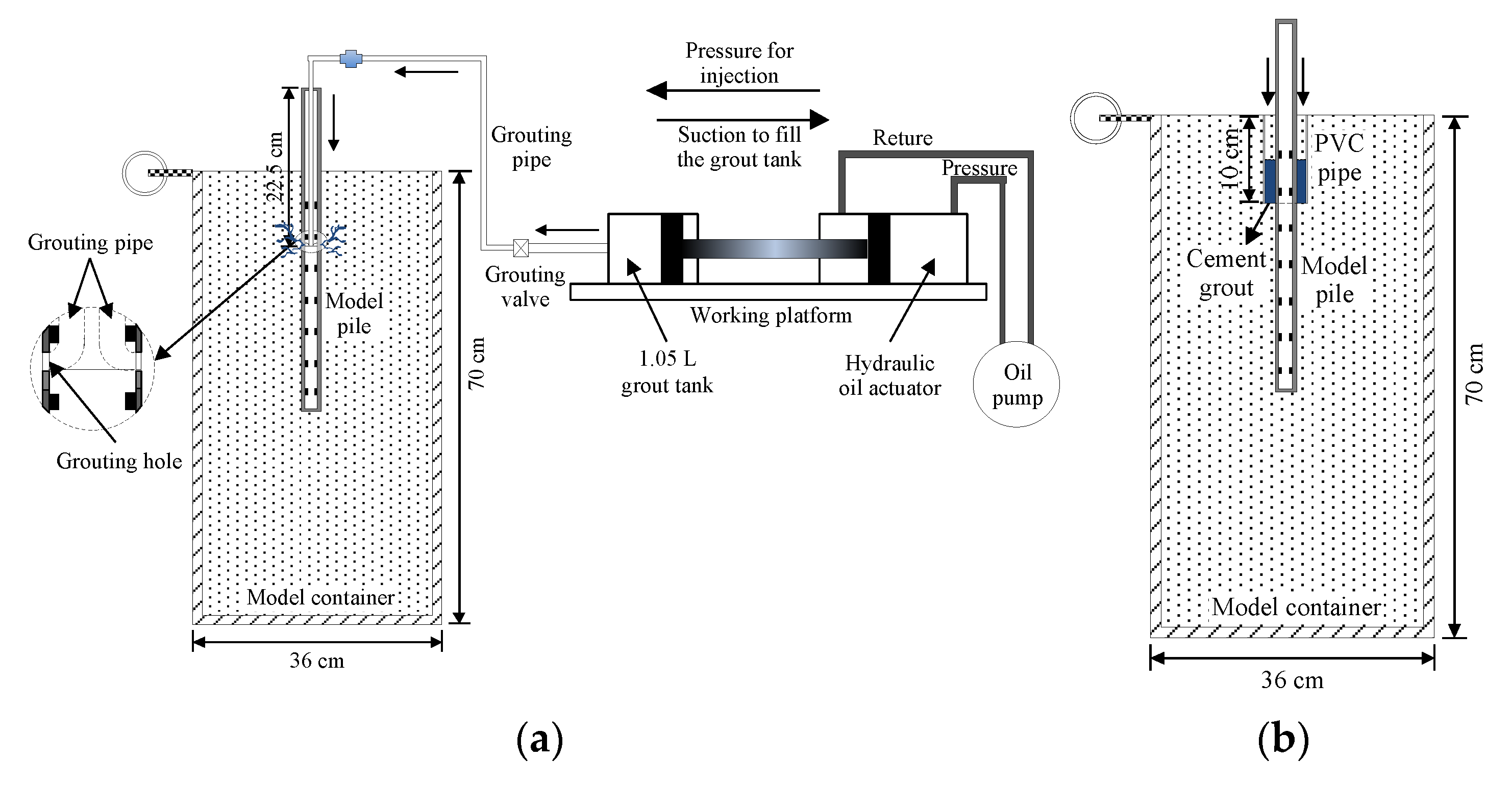
To explore the effect of post-grouting on the response of axially loaded piles in calcareous sand, two types of grouting tests were performed in this study, including grouting at the side of the pile and grouting at the pile shaft with Polyvinyl Chloride (PVC) pipes. Grouting at the side of the pile is referred to as annular point grouting, and grouting at the pile shaft with PVC pipe is referred to as ideal-geometry grouting. A detailed schematic diagram of the two grouting methods is shown in Figure 2. In the annular point grouting test, two grouting pipes are symmetrically arranged in the model pile, and the bottom of the grouting pipe is connected through the hole in the inner side of the tubular pile. The distance between the bottom of the grouting pipe and the pile head is 22.5 cm, the diameter of the grouting pipe is 8 mm, and the hole size of the pile shaft is 8 mm and sealed by a pushpin (Figure 2a). The ideal-geometry grouting test is performed by grouting the PVC pipe set on the pile shaft. After pile driving, the PVC pipe is pressed into the pile circumference with the model pile as the center, and the sand sample is excavated (Figure 2b).
Various grouting devices have been developed to satisfy the requirements of the post-grouting test. A grouting device mainly includes a hydraulic pump, a working platform, a storage tank, and a hydraulic oil actuator, as shown in Figure 2. Before the annular point grouting test, the homemade grouting device is adopted to inject water into the grouting tube to break the pushpin on the pile hole to ensure a smooth grouting pipeline; then, the prepared cement grout is stored in a 1.05 L grout tank after being transported through the grouting device. The grouting pipe is connected to the grouting pipe in the pile shaft by a three-way joint, and the hydraulic pump is used to adjust the pressure and rate of grouting. Cement grout is injected into the foundation soil to complete the annular point grouting test. The water-cement ratio of the cement grout prepared in this test is selected as 0.6. The hydraulic pump is employed to adjust the pressure and rate of grouting during the implementation process. During the whole grouting test of grout injected into two sand samples, the pressure fluctuates between 0.25 MPa and 0.3 MPa, and the injection volume of the cement grout is approximately 200 mL. The surface of the two foundation soils is uplifted, and the post-side-grouting test is completed.
For the ideal-geometry grouting test, the size of the PVC pipe should be determined before the test. The purpose of this test is to compare the bearing behavior of the annular point side grouted pile and the ideal-geometry grouted pile to maintain identical required amount of grout for the two grouting methods. The diameter and height of the PVC pipe were calculated to be 5 cm and 10 cm, respectively, based on the grouting process of the annular point side grouted pile. The annular point side grouting test is performed to strengthen the range from the surface of the model foundation to a depth of 10 cm, and the hole position of the annular point grouted pile is 10 cm from the surface; thus, the height of the PVC pipe can be determined. The homemade PVC pipe is pressed into the pile circumference, with the model pile as the center after pile driving, and the sand sample in the PVC pipe is removed. Identical water-cement ratio as that of the ideal-geometry grouted pile is prepared for the annular point side grouted pile, the cement grout is poured into the PVC pipe, and the PVC pipe is subsequently pulled out to complete the ideal-geometry grouting test. In this test, the detailed parameters of the model piles are listed in Table 2.
2.4. Test Setup, Test Method and Instrumentation
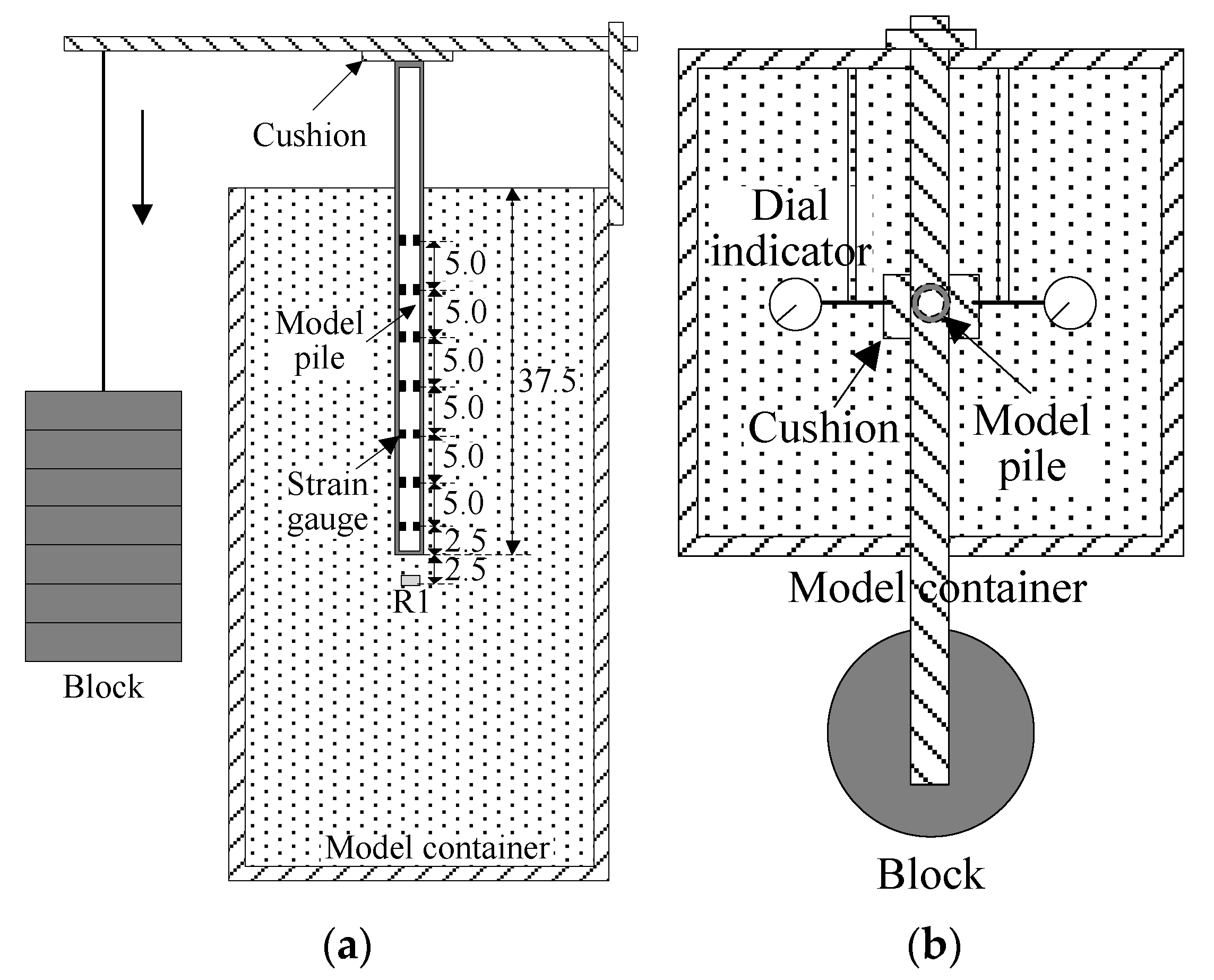
For ungrouted piles, the axial compressive load test is conducted after the completion of pile driving, and the standing time is not less than 24 h. For annular point grouted and ideal-geometry grouted piles, post-side-grouting is conducted immediately after the completion of pile driving, and the axial compressive load test is conducted on the grouted pile after the completion of grouting and not fewer than 20 days of rest. Based on the actual situation of the indoor model test, the axial compressive static load test adopts the rapid maintenance load method, and the maintenance time of each load level is not less than 1 h. When the settlement rate of the pile head under this load level converges, the next load level can be applied. The loading method was in accordance with the Chinese Technical Code for Testing of Building Foundation Piles [22]. The ultimate axial compressive bearing capacity of the ungrouted pile and grouted pile is preliminarily determined by the preloading test. Based on the 1/10 grading load of this value, the first loading amount is taken as twice the grading load, while the unloading amount of each stage is twice as high as that of the loading stage. The termination loading conditions are as follows: (1) the settlement of a single pile under a certain level of loading is five times that under the previous load level. (2) The settlement of a single pile, under a certain level of loading, is twice that under the previous load level, and it does not reach relative stability in that the settlement of the pile head does not exceed 0.1 mm after 1 h. (3) The single pile sinks sharply under a certain level of load so that it cannot be read. (4) The loading equipment reaches the maximum limit. The axial compressive static load test of a single pile is shown in Figure 3.
To study the response of axially loaded single piles in calcareous sand, various strain gauges are symmetrically installed along the longitudinal direction of the inner side of the steel pipe pile to measure the strain of different sections of the steel pipe pile. Two strain gauges are symmetrically arranged for each section of the steel pipe pile, and seven sections are arranged in the pile shaft from top to bottom, according to the actual penetration depth. The specific arrangement is shown in Figure 3. During the loading process, the strain gauge data can be acquired by the testing system. The measurement of the pile head displacement is an important part of the static load test, which can be obtained by a dial indicator with an accuracy of 0.01 mm. A steel block is placed on the head of the model pile, two dial indicators are symmetrically arranged at the left and right ends of the steel block, and the average value of the results is used to determine the pile head settlement. In addition, to measure the earth pressure at the pile base, a strained earth pressure cell R1, with a diameter of 17 mm, is arranged 2.5 cm from the end of the pile, as shown in Figure 3.
3. Analysis of the Loading Test Results
3.1. Load-Settlement Response of a Single Pile
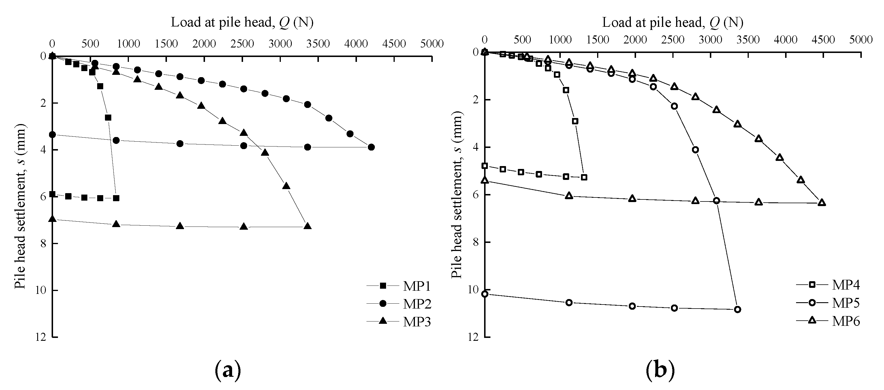
The load-settlement curves can be obtained by the loading test data for the six model piles. The load-settlement responses at the pile head of the six model piles under compression are shown in Figure 4.
Figure 4 shows that the load-settlement curves of ungrouted piles have obvious inflections, and the load-settlement curves of grouted piles tend to be smoother than those of ungrouted piles. The load-settlement curve of each single pile is relatively gentle and approximately linear during the initial load increments. The settlement of a single pile gradually increases with applied load, and the load-settlement curve of a single pile presents an obvious nonlinearity. For the ungrouted piles, when the ultimate load is reached, the load-settlement curve sharply plunges, which represents penetration failure of the pile. For grouted piles MP2 and MP6, the bearing capacity of a single pile after grouting has been greatly improved so that it is loaded to the device limit without a distinct inflection. Prakash and Sharma [23] and Li et al. [24] proposed that the load prior to failure is determined to be the axial compressive bearing capacity of a single pile, while the maximum test load is taken to be the axial compressive bearing capacity of a single pile in the case of no obvious inflections. Therefore, the ultimate bearing capacities of single piles MP1, MP2 and MP3 are 735 N, 4200 N, and 3080 N, respectively. The ultimate bearing capacities of MP4, MP5 and MP6 are 1200 N, 3080 N, and 4480 N, respectively.
Figure 4 also shows that MP4 for ungrouted piles has greater bearing capacity than MP1 because the soil around the pile is compacted by lateral extrusion of siliceous sand in the process of pile driving, and the lateral pressure increases. The calcareous sand is subjected to lateral compression and prone to particle breakage, due to its own particularity in the process of pile driving, which leads to the loosening of the soil around the pile, thus reducing the lateral pressure to some extent. The bearing capacity of a single pile is substantially improved after grouting in both siliceous sand and calcareous sand, and calcareous sand formations are effectively improved by injected cement grout; therefore, the single pile exhibits roughly identical bearing capacity in the two types of sand formations. In calcareous sand, the annular point grouted pile MP2 has greater ultimate bearing capacity than the ideal-geometry grouted pile MP3, while the annular point grouted pile MP5 in siliceous sand has a lower ultimate bearing capacity than the ideal-geometry grouted pile MP6, which indicates that annular point grouting promotes substantial discreteness in improving the response of the axial loaded single pile. In addition, the bearing capacities of post-grouted piles in calcareous sand and siliceous sand increase by 457–571% and 257–373%, respectively. The test results show that the post-grouting improves the bearing capacity of piles in calcareous sand better than that of piles in siliceous sand. Because that the surface of calcareous sand is uneven and porous, the injected cement grout fills its holes and pores to form a whole with high strength.
3.2. Load Transfer Response of a Single Pile
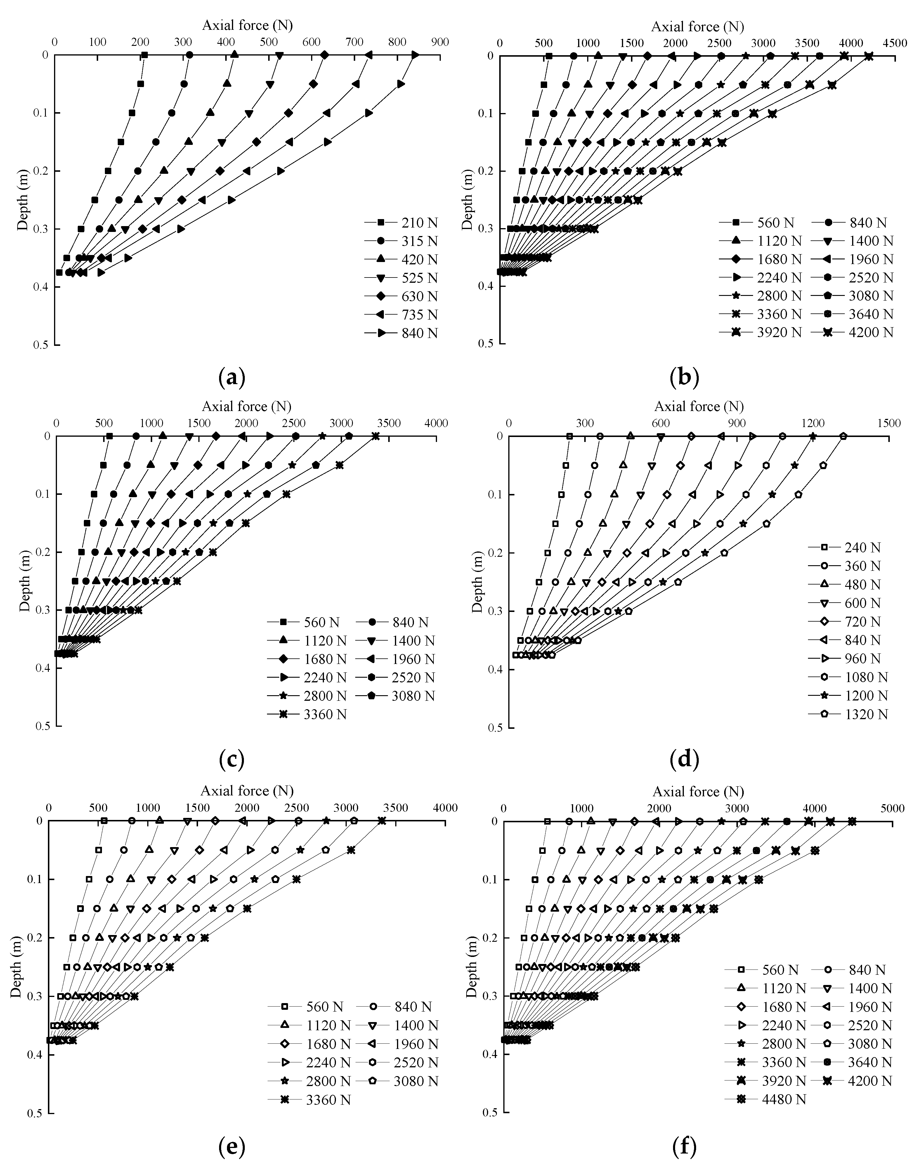
The load transfer response is a comprehensive reflection of the axial bearing behavior of a single pile, which can reflect not only the mobilization of shaft resistance but also the bearing performance of the pile tip. The axial force distribution of single piles MP1 to MP6, under different loading levels, can be obtained by the data collected from strain gauges. The strain is measured by the strain gauge arranged on each pile section, and the average strain value εi of pile section i can be calculated as follows:
where εi1 and εi2 are the strain values measured by the strain gauges on both sides of pile section i.
After the average strain value of pile section i is obtained, the axial force Ni of pile section i can be calculated as follows:
where Em is the elastic modulus of a single pile and Am is the cross-sectional area of a single pile.
The axial force distributions of each pile under different loading levels are shown in Figure 5.
Figure 5 shows that the axial force of the pile decreases with increasing depth at different loading levels. The slope of the axial force curve is larger during the initial load increments, which shows that the mobilized shaft resistance of the pile and the axial force transferred to the lower segment of the pile shaft are small. With increasing load, the slope of the axial force curve decreases, which indicates that the shaft resistance of the pile gradually develops, that axial force is gradually generated at the lower part of the pile shaft, and the tip resistance is also gradually mobilized. This also fully illustrates that the side friction of the soil around the pile gradually develops from the head of the pile to the bottom of the pile during the downward transmission of the axial load along the pile shaft, and the attenuation rate of the axial load reflects the distribution of the shaft resistance. In addition, grouting will change the stress path of the soil around the pile, which will affect the load transfer responses of the pile. The attenuation rate of the axial force of grouted piles is higher than that of ungrouted piles. Thus, grouting at the side of the pile increases the effective horizontal stress in the soil surrounding the pile, which increases the shear strength of the soil, and the increase in shaft resistance can effectively offset the transmission of the axial force of the pile shaft.
3.3. Mobilized Shaft Resistance of a Single Pile
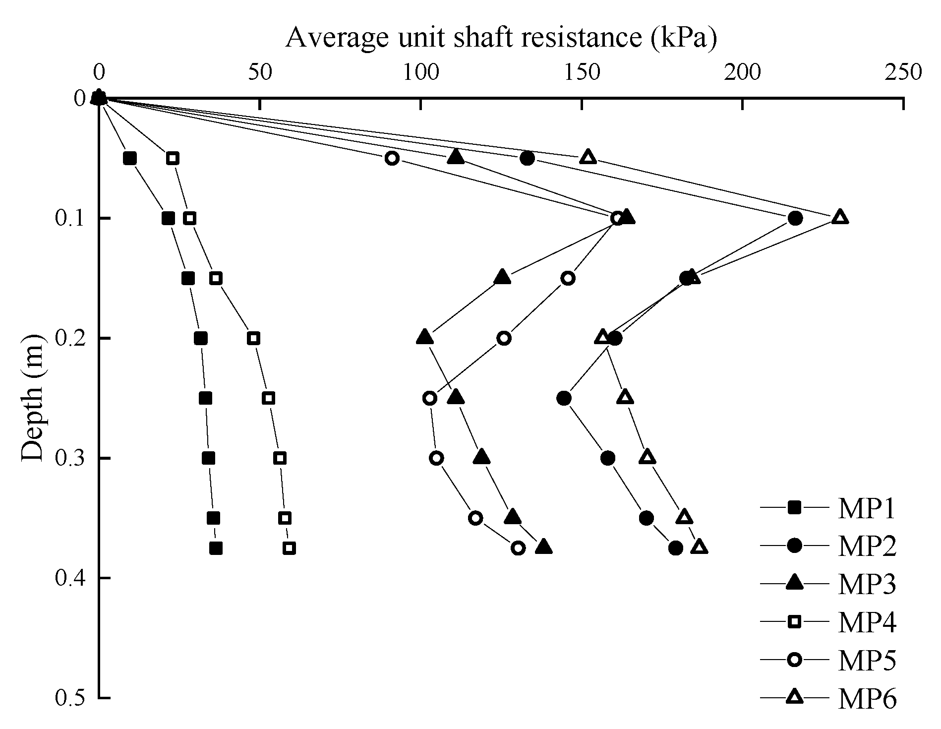
Figure 6 shows the distribution of the average unit shaft resistance of each single pile under ultimate loading. The shaft resistance is a process that gradually develops from the upper soil layer to the lower soil layer. For ungrouted piles, the shaft resistance of the pile gradually increases with the increase in buried depth when the load increases, while the grouted piles obviously increase the horizontal effective stress of the surrounding soil due to the grouting at the side of the pile, and the shaft resistance of the pile increases significantly; therefore, the extreme point of shaft resistance occurs approximately 0.1 m from the surface. Figure 6 shows that the average unit shaft resistances of single piles MP1, MP2, MP3, MP4, MP5, and MP6 under ultimate loads are 28.23 kPa, 167.33 kPa, 123.87 kPa, 44.26 kPa, 121.86 kPa, and 177.65 kPa, respectively. The shaft resistance of the ungrouted pile in calcareous sand is less than that in siliceous sand, which is mainly caused by the decrease in shaft resistance due to the particle breakage of calcareous sand during pile driving. In addition, compared with that of the ungrouted pile, the shaft resistance of the grouted pile improves substantially, which indicates that the injected cement grout effectively improves the physical and mechanical properties of the undisturbed surrounding soil. In addition, the effective stress of the soil around the pile increases, thereby enhancing the strength of the surrounding soil. After grouting at the side of the pile, the cement grout and calcareous sand particles condense to form stable cement-stabilized soil; therefore, the pile-soil interaction system forms a new structure, which greatly increases the shaft resistance of a single pile in calcareous sand, and the mobilization of side friction in calcareous sand basically demonstrates identical characteristics as those of side friction in siliceous sand.
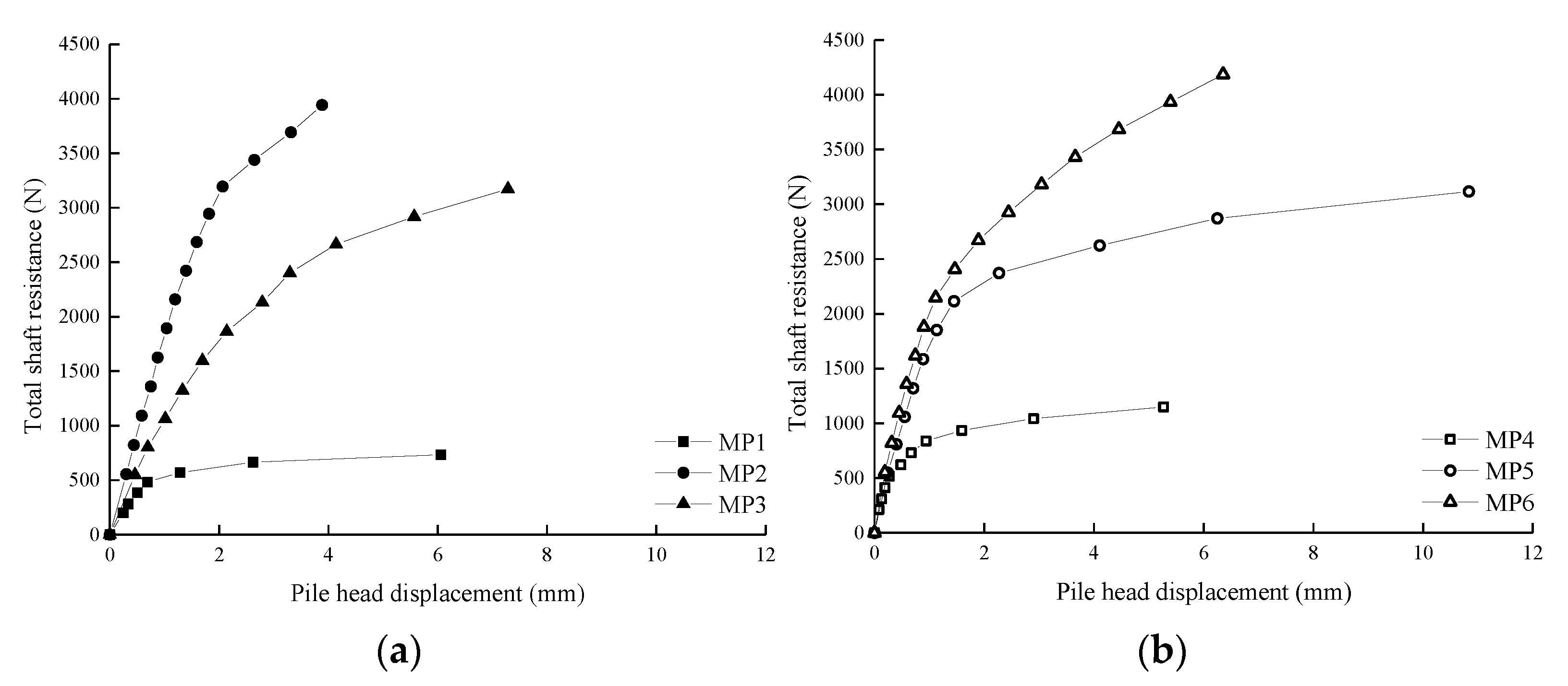
The relationship between total shaft resistance and pile head settlement for each pile, in two types of sandy soil, are plotted in Figure 7. Figure 7 shows that the variation in total shaft resistance of each pile is roughly identical to the displacement of the pile head, while the total shaft resistance of the grouted pile is significantly improved. The injected cement grout fills the pores, condenses into cement-stabilized soil with high strength, increases the resistance and roughness of the shear interface at the pile side, enhances the interaction between pile and soil, and improves the shaft resistance mobilization. Thus, the single pile with post-grouting has greater shaft resistance than the single pile without post-grouting, which effectively improves the stability of the bearing performance of the pile.
3.4. Mobilized Tip Resistance of a Single Pile under Compression
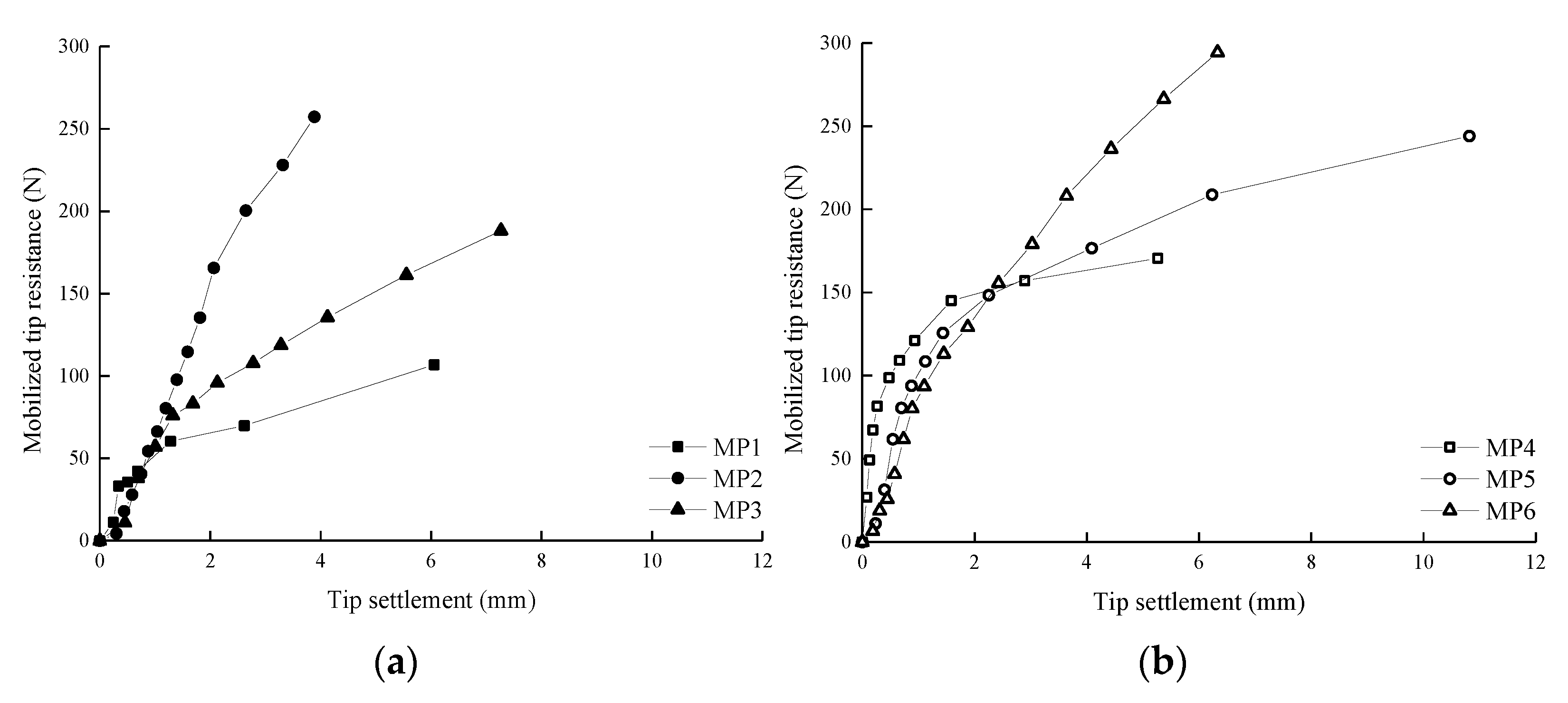
Figure 8 shows the relationship between tip resistance and tip settlement for each pile, in two types of sandy soil. Figure 8 shows that the tip resistance of a single pile varies with the change in tip displacement. The pile tip resistance increases rapidly with the displacement of the pile tip during the initial loading stage. With increasing load, the pile tip resistance gradually mobilizes. After reaching the ultimate load, the grouted pile has a larger tip resistance than the ungrouted pile because of the strengthening effect of the grouted lateral soil strength on the tip resistance of the pile. Thus, the tip resistance can also be improved by the enhancement in the surrounding soil, due to side grouting. In addition, the curves of the tip resistance versus the tip settlement show hardening characteristics after exceeding the ultimate load. The literature [25,26,27] also reported the hardening phenomenon of pile tip resistance in fine sand and calcareous sand after reaching the ultimate load.
4. Analysis of Grout Distribution and Bearing Mechanism of a Post-Grouted Single Pile
4.1. Grout Penetration and Diffusion of a Post-Grouted Single Pile
To observe the infiltration and expansion of the injected grout in the model foundation, the sand samples in the model container were excavated after the static load test was completed. For the annular point grouted pile, the cement grout migrates upward along the pile shaft and diffuses horizontally during the excavation process, forming a stable structure of cement-stabilized soil with the foundation soil. For the ideal-geometry grouted pile, the cement grout poured into the PVC pipe forms a cement-stabilized mass of the same size as the PVC pipe, and the cement-stabilized mass is fastened to the pile shaft. Its surface condenses with the sand sample to form a new structure, so the interaction among the pile, soil, and grout enters a new structural equilibrium state.
The cement-stabilized mass extracted after excavation is cleaned, and its size is measured to analyze the grout diffusion range in the foundation soil. The cement-stabilized masses, extracted from annular point grouted piles MP2 and MP5, and ideal-geometry grouted piles MP3 and MP6 are shown in Figure 9. The figure shows that the grout migrates upward along the side of the annular point grouted pile and forms a thick “flange body”. The grout migration height is approximately 6–8 cm (about 3–4D), and the cement soil thickness formed on the pile shaft is approximately 2–6 mm. The ideal-geometry grouted pile does not spread due to the restriction of the grout poured into the PVC pipe, but an uneven surface is formed at the bottom of the cement-stabilized mass due to the penetration of the self-weight into the foundation soil. Finally, the cement grout poured into the PVC pipe forms a cylindrical cement-stabilized mass with a height of approximately 10 cm and a diameter of approximately 5 cm.
4.2. Bond Strength between the Cement Grout and the Pile
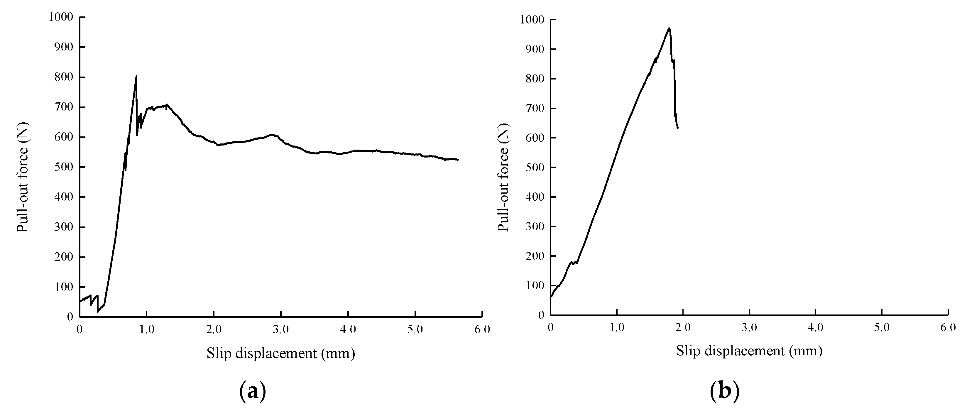
To evaluate the bond strength between the cement grout pressed into the side of the pile and the pile shaft, the two ends of the cement-stabilized mass of the ideal-geometry grouted pile were ground flat, and a pull-out test was conducted to detect the shear strength between the cement-stabilized mass and the pile shaft. The pull-out force-slip curves, between the cement-stabilized mass and the pile shaft in calcareous sand and siliceous sand, obtained in this test are shown in Figure 10.
Figure 10 shows that the relationship between the pull-out load and slip is approximately linear during the initial loading stage. When the slip amount is small, the pull-out force increases rapidly, and the initial slope is large. After reaching the peak point, the drawing load required by the specimen decreases gradually with increasing slip, and the pull-out force-slip curve shows a downward trend. After being reduced to a certain value, the required pull-out load of the specimen gradually stabilizes. Splitting failure of the siliceous sand specimen occurs during the pull-out process, which results in failure to measure the residual section of the pull-out force-slip curve. Figure 10 also shows that the maximum pull-out loads of the calcareous sand and siliceous sand specimens are 803 N and 971 N, respectively. To obtain the shear strength between the cement-stabilized mass and the pile, the pull-out force is divided by the surface area of the cement-stabilized mass that covers the length of the model pile. The maximum shear strengths of the calcareous sand and siliceous sand specimens are 142 kPa and 172 kPa, respectively. Since both ends of the cement-stabilized mass are ground flat, the cover length of the model pile is taken as 90 mm when calculating the shear strength. The shear strength obtained in this test is similar to the result obtained in the static load test. This may be due to the excessively long time that the specimens were tested in the pull-out test and drying shrinkage, which affects the bonding strength between the cement-stabilized mass and the pile shaft.
4.3. Analysis of Axial Bearing Mechanism of Post-Side-Grouted Pile
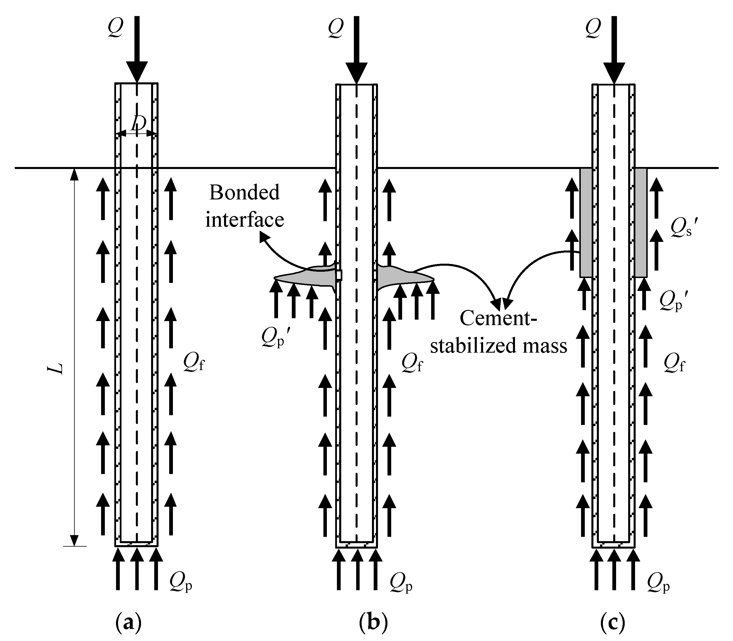
According to the comparative analysis of the test results, the post-side-grouted pile has significantly greater axial bearing capacity than the ungrouted pile, and the ideal-geometry grouted pile has greater axial bearing capacity than that of the annular point grouted pile. Combined with the morphological characteristics of the cement-stabilized mass, the contact interface between the cement-stabilized mass of the annular point grouted pile and the model pile is much smaller than that of the ideal-geometry grouted pile, and the annular point grouted pile and model pile show a separation state after loading. Therefore, it can be considered that, under the continuous increase in vertical load, the contact interface between the cement-stabilized mass of the annular point grouted pile and the pile shaft cannot provide sufficient cohesive force. At a certain axial load, the bonding surface slips, so the cement-stabilized mass and model pile fail to bear together, which seriously affects the bearing capacity of the grouted pile. Based on the above analysis, the force diagram of the three pile types is drawn, as shown in Figure 11, and the axial bearing mechanism of the post-side-grouted pile is analyzed.
It can be seen from the foregoing that the axial load of the model pile is supported by the tip resistance, Qp, and the total shaft resistance, Qs, that is, Q = Qp + Qs.
- (1)
- For the ungrouted pile (Figure 11a), the total shaft resistance is equivalent to the shaft resistance along the pile shaft, Qf, i.e., Qs = Qf. The axial bearing capacity, Q1, can be calculated as follows:where u is the perimeter of the cross section of the model pile; qsi is the unit shaft resistance between the pile and layer soil i around the pile, which is related to the compactness of the soil and the normal stress of the pile-soil interface; li is the thickness of layer soil i around the pile; qp is the pile tip stress; Ap is the pile tip area.
- (2)
- For annular point grouted piles (Figure 11b), the model pile and cement-stabilized mass form a common interaction. The radial dimension of the cement-stabilized mass is larger, the longitudinal dimension is smaller, the bonding surface between the model pile and the cement-stabilized mass is small, and it easily slips when the load is large. The bearing mechanism of the annular point grouted pile is different before and after the relative slip between the model pile and the cement-stabilized mass.
Before the slip failure of the bonding surface, the annular point grouted pile can be considered a special-shaped pile. The total shaft resistance, Qs, includes the shaft resistance along the pile shaft, Qf, and axial bearing capacity, Qp’, which is provided by the cement-stabilized mass, i.e., Qs = Qf + Qp’. The axial bearing capacity, Q2, of the annular point grouted pile, in this stage, can be expressed as:
where qps is the vertical stress at the bottom of the cement-stabilized mass, and As is the equivalent area of the cement-stabilized mass.
The vertical bearing capacity, Qp’, provided by the cement-stabilized mass is transferred to the model pile through the bonding surface. As the increase in the applied load, Qp’ also increases. When Qp’ increases to a certain extent, slip failure occurs at the bonding surface. At this time, the bonding surface becomes the contact interface. The model pile and cement-stabilized mass become two independent units and no longer bear the load together. The axial bearing capacity, Q2, of the annular point grouted pile at this stage can be expressed as:
where qs’ is the unit shaft resistance at the interface between the model pile and the cement-stabilized mass, and ls is the height of the bonding surface between the cement-stabilized mass and the pile shaft.
- (3)
- For the ideal-geometry grouted pile (Figure 11c), the bonding area between the model pile and the cement-stabilized mass is relatively large. After the cement-stabilized mass is excavated at the end of the loading, it is found that there is no relative slip between the cement-stabilized mass and the model pile, so the two can be regarded as a whole. Figure 11 shows that, different from the annular point grouted pile, the cement-stabilized mass of the ideal-geometry grouted pile is equivalent to increasing the diameter of a section of pile, and there is a large shaft resistance, Qf, between the cement-stabilized mass and the soil layer. The total shaft resistance, Qs, of the ideal-geometry grouted pile includes the shaft resistance along the pile shaft, Qf, which is provided by the pile shaft without the cement-stabilized mass, the shaft resistance along the pile shaft, Qf’, which is provided by the pile shaft with the cement-stabilized mass and the vertical bearing capacity Qp’ provided by the cement-stabilized mass, i.e., Qs = Qf + Qf’ + Qp’. The axial bearing capacity, Q3, can be expressed as:where u’ is the perimeter of the cement-stabilized mass; qsi’ is the friction stress between layer soil i around the pile and the cement-stabilized mass; li’ is the thickness of layer soil i outside the cement-stabilized mass.
Combined with the distribution of the unit shaft resistance along the pile shaft, shown in Figure 6, the cement-stabilized mass of the annular point grouted pile and ideal-geometry grouted pile can provide great axial bearing capacity. The major portion of the load is supported by the cement-stabilized mass of the annular point grouted pile and ideal-geometry grouted pile during the initial load, and the settlement of the pile is very small; thus, the shaft resistance of the lower pile section of the cement-stabilized mass is small. With increasing axial load, the cement-stabilized mass of the annular point grouted pile and ideal-geometry grouted pile begins to settle with the pile shaft, and the shaft resistance of the lower pile section of the cement-stabilized mass gradually increases. In addition, the protruding cement-stabilized mass has a certain compaction effect on the lower soil layer during loading, which increases the normal stress at the pile-soil interface of the lower pile section. Hence, the lower pile section of the annular point grouted pile and ideal-geometry grouted pile have greater shaft resistance than the ungrouted pile.
The cement-stabilized mass of the ideal-geometry grouted pile is firmly bonded to the pile shaft of the model pile. The test shows that the pile-soil system forms a close cooperative system, which is the most ideal effect of post-grouting on the side of the pile. For the annular point grouted pile, the cement grout diffuses, mainly, along the horizontal direction after entering the soil layer from the grouting hole, and the bonding surface between the cement-stabilized mass and the pile shaft is small. The cooperative bearing capacity of the cement-stabilized mass and model pile is restricted by the ultimate bonding ability of the bonding surface, which causes its bearing capacity effect inferior to that of the ideal-geometry grouted pile.
5. Discussion
The test results have proven that the post-grouting technique can increase the bearing capacity of a pile in calcareous sand by enhancing the shaft resistance and tip resistance, and calcareous sand formations can be effectively improved by injected cement grout. Table 3 shows the measured ultimate bearing capacity of each single pile, the corresponding measured values of the total shaft resistance, tip resistance, and their increase range. The table shows that, under the ultimate load, the load sharing of tip resistance is relatively small, which indicates that the single pile is mainly borne by the shaft resistance during the process of axial loading and the pile head load is mostly supported by the shaft resistance under the ultimate load. The total shaft resistance of annular point grouted piles MP2 and MP5 increases by 175.26–492.93%, and the tip resistance increases by 33.12–267.14%. The total shaft resistance of ideal-geometry grouted piles MP3 and MP6 increases in the range of 301.34–338.95%, and the tip resistance increases by 87.26–130.00%. The test results show that side grouting significantly improves the shaft and tip resistances of the pile foundation. It is also evident that the total shaft resistance and tip resistance of annular point grouted piles are more discrete than those of ideal-geometry grouted piles. Directional flow grouting can effectively increase the response of the axially loaded pile. In addition, the tip resistance of piles with post-grouting is improved compared with piles without post-grouting, which indicates that grouting at the side of the pile can not only enhance the strength of the soil at the side of the pile but also improve the strength of the bearing layer at the end of the pile. This conclusion is consistent with the conclusion, given by Wan et al. [28], that the mobilization of the tip resistance can be enhanced by the soil improvement at the pile side, due to side grouting.
As mentioned above, the increase in post-grouting on the bearing capacity of piles in calcareous sand is better than that of piles in siliceous sand. Simultaneously, in Table 3, the post-grouted pile in calcareous sand also has better increased ratio of total shaft resistance than that in siliceous sand, which further indicates that the injected cement grout fills the concave and convex holes on the surface of calcareous sand, enhances the interface meshing between calcareous sand particles and cement grout, and effectively improves the interface structure performance. The results are consistent with the conclusion, reported by Wan et al. [29], that cement stabilized calcareous sand has higher integral strength than cement stabilized siliceous sand using microscopic test methods.
Through the abovementioned analysis, the bearing capacity of an annular point grouted pile increases discretely, due to the uncertainty of the grout flow direction and the formation of an irregular cement-stabilized mass during the grouting process. Directional flow grouting can form an ideal geometric shape and can effectively control the amount of grouting, and reduce the uncertain factors in the grouting process, to achieve the expected effect of post grouting. Some scholars [30,31,32,33] developed a device for forming an ideal geometric shape of prefabricated piles and bored piles after grouting to solve the problem of the uncertainty of the grout flow direction and the difficulty of forming ideal geometric shapes, which can effectively control the grouting amount and grouting pressure to form an ideal geometric shape. The increased range of the shaft resistance and tip resistance can be predicted according to the ideal geometric size of the grout bubble, so the post-grouting technique is more reasonable. Therefore, a directional grouting device should be adopted in future engineering practice to reduce the uncertainties in the post-grouting process and ensure the expected effect of post-grouting.
Given that this study is limited to small-scale model tests, further validation is required from field full-scale load tests, especially field full-scale group tests. In addition, the test results and related analysis in this paper are limited to calcareous sand in the South China Sea, which is difficult to directly extend to any area because of its regional characteristics, so future studies will focus on performing relevant quantitative research. The main purpose of this paper is to elucidate the axial bearing mechanism of post-grouted piles, as well as provide a theoretical basis and technical support for the popularization and application of post-grouted piles in calcareous sand, and it is also instructive for improving the safety of island and reef engineering and reducing the economic cost.
6. Conclusions
This paper presents a model test of an axially loaded single pile in a calcareous sand foundation. The axial bearing behavior of single piles, with and without post-grouting, in calcareous sand are studied, and the test results are compared with those of single piles, with and without post-grouting, in siliceous sand. The distribution of the cement-stabilized mass and the bearing mechanism of grouted piles are analyzed by considering the excavation observation of grouted single piles. Based on the analyses and discussions of this study, the following conclusions can be reached:
- The change in shaft resistance, caused by the lateral extrusion of calcareous sand during pile driving, is less than the negative effect caused by particle breakage; therefore, the response of an ungrouted pile subjected to axial load in calcareous sand is lower than that in siliceous sand. After grouting, the axial bearing capacity of a single pile is greatly improved in both model foundations, and the calcareous sand formation is significantly enhanced by the injected cement grout; hence, the grouted single pile shows basically identical bearing behavior in the two types of sandy soil formations. In addition, compared with annular point grouting, ideal-geometry grouting has more obvious advantages in improving the bearing characteristics of pile foundations and shows higher stability in improving the bearing properties of pile foundations.
- Post-grouting has affects the load transfer responses of the pile. Given that grouting at the side of the pile increases the effective horizontal stress of the soil around the pile, the enhanced shear strength of the soil can effectively offset the transmission of the axial force of the pile, resulting in the load attenuation of the grouted pile along the depth direction is faster than that of the ungrouted pile.
- The particle breakage characteristics of calcareous sand during pile driving will reduce the shaft resistance of the pile, so the ungrouted single piles in calcareous sand has a lower shaft resistance than that in siliceous sand. The grout fills the holes and pores on the surface of calcareous sand and enhances the surrounding soil by the solidification effect of injected cement grout, which forms a new structural equilibrium state for the pile-soil interaction system and effectively improves the physico-mechanical properties of the surrounding soil. The grouted pile has a higher shaft resistance than the ungrouted pile, and the increased ratio of the total shaft resistance after grouting in calcareous sand formations is better than that of piles in siliceous sand formations.
- Grouting at the side of the pile can not only improve the strength of the surrounding soil but also increase the strength of the bearing layer at the pile tip so that the single pile without post-grouting has a lower tip resistance than that of the single pile with post-grouting. This result indicates that the mobilization of the tip resistance can be enhanced by the soil improvement at the pile side due to side grouting.
- The analysis of the static load test and excavation observations shows that the annular point grouting does not have an obvious reinforcement effect due to the uncertainty of the grouting flow direction, which results in a large discreteness of the increase in bearing capacity after grouting. The use of an ideal-geometry grouting device can effectively control the key parameters, such as the grouting amount and grouting pressure, so it can form an ideal geometric shape, which standardizes the application of the post-grouting technique.
- The analysis of the bearing mechanism of the post-side-grouted pile shows that, compared with the annular point grouted pile, the ideal-geometry grouted pile forms a larger bonding surface between the cement-stabilized mass and the pile shaft, which forms a more stable pile-soil interaction structure system. It is suggested that the directional grouting device should be used in actual grouting projects in the future to realize pile-soil effective bonding and load transfer.
Author Contributions
Conceptualization, G.D. and F.Z.; investigation, Z.W. and H.L.; data curation, Z.W.; writing—original draft preparation, Z.W.; writing—review and editing, Z.W., H.L., G.D. and F.Z.; supervision, G.D. and F.Z.; project administration, H.L. and G.D.; funding acquisition, Z.W. All authors have read and agreed to the published version of the manuscript.
Funding
This research was funded by the National Natural Science Foundation of China (No. 52008100) and Natural Science Foundation of Jiangsu Province (No. BK20200400).
Institutional Review Board Statement
Not applicable.
Informed Consent Statement
Not applicable.
Data Availability Statement
Not applicable.
Acknowledgments
The authors would like to express appreciation to the editors and reviewers for their valuable comments and suggestions.
Conflicts of Interest
The authors declare no conflict of interest. The funders had no role in the design of the study; in the collection, analyses, or interpretation of data; in the writing of the manuscript, or in the decision to publish the results.
References
- Joer, H.A.; Randolph, M.F.; Gunasena, U. Experimental modeling of the shaft capacity of grouted driven piles. Geotech. Test. J. 1998, 21, 159–168. [Google Scholar]
- Wang, X.Z.; Jiao, Y.Y.; Wang, R.; Hu, M.J.; Meng, Q.S.; Tan, F.Y. Engineering characteristics of the calcareous sand in Nansha Islands, South China Sea. Eng. Geol. 2011, 120, 40–47. [Google Scholar] [CrossRef]
- Meng, Q.S.; Wang, R.; Yu, K.F.; Qin, Y.; Wei, H.Z.; Wang, X.Z. Characteristics of rocky basin structure of Yongshu reef in the Southern South China Sea. Mar. Georesour. Geotechnol. 2014, 32, 307–315. [Google Scholar] [CrossRef]
- Nauroy, J.F.; Le Tirant, P. Driven piles and drilled and grouted piles in calcareous sands. In Proceedings of the 17th Annual Offshore Technology Conference, Houston, TX, USA, 6 May 1985; pp. 83–91. [Google Scholar]
- Joer, H.A.; Randolph, M.F. Modeling of the shaft capacity of grouted driven piles in calcareous soil. In Proceedings of the International Conference on Design and Construction of Deep Foundation, Orlando, FL, USA, 1 January 1994; pp. 873–887. [Google Scholar]
- Angemeer, J.; Carlson, E.D.; Klick, J.H. Techniques and results of offshore pile load testing in calcareous soils. In Proceedings of the 5th Annual Offshore Technology Conference, Houston, TX, USA, 28 April 1973; pp. 677–692. [Google Scholar]
- Dutt, R.N.; Cheng, A.P. Frictional response of piles in calcareous deposits. In Proceedings of the 16th Annual Offshore Technology Conference, Houston, TX, USA, 7 May 1984; pp. 527–530. [Google Scholar]
- Poulos, H.G.; Randolph, M.F.; Semple, R.M. Evaluation of pile friction from conductor tests. In Proceedings of the International Conference on Calcareous Sediments, Perth, Australia, 1 July 1988; pp. 599–605. [Google Scholar]
- Renfrey, G.E.; Waterton, C.A.; Goudoever, P. Geotechnical data used for the design of the North Rankin A platform foundation. In Proceedings of the International Conference on Calcareous Sediments, Perth, Australia, 1 July 1988; pp. 343–357. [Google Scholar]
- Liu, X.C.; Xu, J.; You, X.P.; Xie, F. Study on bearing behavior of large diameter driven steel pipe pile in coral reef geology. Ocean Eng. 2019, 37, 157–163. [Google Scholar]
- Nauroy, J.F.; Le Tirant, P. Model tests of piles in calcareous sands. In Geotechnical Practice in Offshore Engineering; ASCE: Austin, TX, USA, 1983; pp. 356–369. [Google Scholar]
- Lee, C.Y.; Poulos, H.G. Tests on model instrumented grouted piles in offshore calcareous soil. J. Geotech. Eng. 1991, 117, 1738–1753. [Google Scholar] [CrossRef]
- McDowell, G.R.; Bolton, M.D. Effect of particle size distribution on pile tip resistance in calcareous sand in the geotechnical centrifuge. Granul. Matter 2000, 2, 179–187. [Google Scholar] [CrossRef]
- Ghazali, F.M.; Sotiropoulos, E.; Mansour, O.A. Large-diameter bored and grouted piles in marine sediments of the Red Sea. Can. Geotech. J. 1988, 25, 826–831. [Google Scholar] [CrossRef]
- Chen, J.W. Application of cast-in-site bored pile in coral rock. Resour. Environ. Eng. 2013, 27, 769–772. [Google Scholar]
- Wan, Z.H.; Dai, G.L.; Gong, W.M. Post-grouting of drilled shaft tips in coral-reef limestone formations: A case study. In Proceedings of the 27th International Ocean and Polar Engineering Conference, San Francisco, CA, USA, 25–30 June 2017; pp. 719–724. [Google Scholar]
- Wan, Z.H.; Dai, G.L.; Gong, W.M. Full-scale load testing of two large-diameter drilled shafts in coral-reef limestone formations. Bull. Eng. Geol. Environ. 2018, 77, 1127–1143. [Google Scholar] [CrossRef]
- Craig, W.H. Installation studies for model piles. In Proceedings of the Symposium on the Application of Centrifuge Modeling to Geotechnical Design, Manchester, UK, 16 April 1984; pp. 440–455. [Google Scholar]
- Ovesen, N.K. The use of physical models in design: The scaling law relationships. In Proceedings of the 7th European Conference on Soil Mechanics and Foundation Engineering, Brighton, UK, 1979; pp. 318–323. [Google Scholar]
- Yegian, M.; Wrights, S.G. Lateral soil resistance displacement relationships for pile foundation in soft clays. In Proceedings of the Offshore Technology Conference, Houston, TX, USA, 28 April–1 May 1973. [Google Scholar]
- Rao, S.N.; Ramakrishan, V.; Raju, G.B. Behavior of pile-supported dolphins in marine clay under lateral loading. J. Geotech. Eng. 1996, 122, 607–612. [Google Scholar] [CrossRef]
- The Professional Standards Compilation Group of People’s Republic of China. Technical Code for Testing of Building Foundation Piles; JGJ 106-2014; China Architecture & Building Press: Beijing, China, 2014.
- Prakash, S.; Sharma, H.D. Pile Foundations in Engineering Practice; John Wiley & Sons: New York, NY, USA, 1990. [Google Scholar]
- Li, S.C.; Zhang, Q.; Zhang, Q.Q.; Li, L.P. Field and theoretical study on the response of super-long bored pile subjected to compressive load. Mar. Georesour. Geotechnol. 2016, 34, 71–78. [Google Scholar] [CrossRef]
- Qin, Y. Model Experimental Study on Bearing Characteristic of Single Pile in Calcareous Sand. Ph.D. Thesis, Institute of Rock and Soil Mechanics, Chinese Academy of Sciences, Wuhan, China, 2015. [Google Scholar]
- Dai, G.L.; Wan, Z.H.; Gong, W.M.; Wang, L. Calculation of bearing capacity for combined post-grouting bored piles based on settlement control. Chin. J. Geotech. Eng. 2018, 40, 2172–2181. [Google Scholar]
- Wan, Z.H.; Dai, G.L.; Gong, W.M. Field and theoretical analysis of the response of axially loaded grouted drilled shaft in extra-thick fine sand. Can. Geotech. J. 2020, 57, 391–407. [Google Scholar] [CrossRef]
- Wan, Z.H.; Dai, G.L.; Gong, W.M. Field study on post-grouting effects of cast-in-place bored piles in extra-thick fine sand layer. Acta Geotech. 2019, 14, 1357–1377. [Google Scholar] [CrossRef]
- Wan, Z.H.; Dai, G.L.; Gong, W.M.; Guo, L.C. Experimental study on micro-erosion mechanism of cement stabilized calcareous sand under seawater enviorment. Rock Soil Mech. 2021, 42, 1871–1882. [Google Scholar]
- McVay, M.; Thiyyakkandi, S.; Joiner, J.; Adams, V. Group Efficiencies of Grout-Tipped Drilled Shafts and Jet-Grouted Piles; University of Florida: Gainesville, FL, USA, 2010. [Google Scholar]
- Schwartz, L.J., III. Demonstrating the Ability to Develop Cylindrical and Spherical Cavity Expansions on Drilled Shafts in Cohesionless Soils through Full Scale Experimentation. Master’s Thesis, University of Florida, Gainesville, FL, USA, 2012. [Google Scholar]
- Thiyyakkandi, S.; McVay, M.; Bloomquist, D.; Lai, P. Measured and predicted response of a new jetted and grouted precast pile with membranes in cohesionless soils. J. Geotech. Geoenviron. Eng. 2013, 139, 1334–1345. [Google Scholar] [CrossRef]
- Thiyyakkandi, S.; McVay, M.; Lai, P. Experimental group behavior of grouted deep foundations. Geotech. Test. J. 2014, 37, 1–18. [Google Scholar] [CrossRef]
Figure 1.
Particle size distributions for the two types of sand.

Figure 2.
Post-grouting apparatus: (a) annular point grouting; (b) ideal-geometry grouting.

Figure 3.
Static load test of a single pile and testing element arrangement (unit: cm): (a) front view; (b) vertical view.
Figure 3.
Static load test of a single pile and testing element arrangement (unit: cm): (a) front view; (b) vertical view.

Figure 4.
Load-settlement curves of piles: (a) calcareous sand; (b) siliceous sand.

Figure 5.
Measured axial force distributions for test piles at different loading levels: (a) MP1; (b) MP2; (c) MP3; (d) MP4; (e) MP5; (f) MP6.
Figure 5.
Measured axial force distributions for test piles at different loading levels: (a) MP1; (b) MP2; (c) MP3; (d) MP4; (e) MP5; (f) MP6.

Figure 6.
Distribution of the average unit shaft resistance of each pile under ultimate loading.

Figure 7.
Total shaft resistance versus pile head displacement curves of each pile: (a) calcareous sand; (b) siliceous sand.
Figure 7.
Total shaft resistance versus pile head displacement curves of each pile: (a) calcareous sand; (b) siliceous sand.

Figure 8.
Curves of the mobilized tip resistance versus tip settlement for each pile: (a) calcareous sand; (b) siliceous sand.
Figure 8.
Curves of the mobilized tip resistance versus tip settlement for each pile: (a) calcareous sand; (b) siliceous sand.

Figure 9.
Cement grout material of a single pile with grouting: (a) MP2; (b) MP3; (c) MP5; (d) MP6.

Figure 10.
Pull-out force-slip curves for the cement grout and pile shaft: (a) calcareous sand; (b) siliceous sand.
Figure 10.
Pull-out force-slip curves for the cement grout and pile shaft: (a) calcareous sand; (b) siliceous sand.

Figure 11.
Equivalent model of the post-side-grouted pile subjected to axial loading: (a) MP1; (b) MP2. (c) MP3.
Figure 11.
Equivalent model of the post-side-grouted pile subjected to axial loading: (a) MP1; (b) MP2. (c) MP3.


Table 1.
Physicomechanical parameters of the sand foundations.
| Sand Type | Density, ρ (g·cm−3) | Moisture Content, ω (%) | Void Ratio, e | Relative Density, ds | Internal Friction Angle, φ (°) | Compression Modulus, Es1–2 (MPa) |
|---|---|---|---|---|---|---|
| Calcareous sand | 1.56 | 22.05 | 0.97 | 2.52 | 36.38 | 15.39 |
| Siliceous sand | 1.68 | 19.78 | 0.84 | 2.58 | 32.31 | 25.13 |
Table 2.
Experimental scheme of the model piles.
| Sand Type | Pile No. | Grouting Method | Grouting Device | Grouting Volume | Grouting Position |
|---|---|---|---|---|---|
| Calcareous sand | MP1 | ungrouting | N/A | N/A | N/A |
| MP2 | annular point grouting | Grouting pump | 200 mL | Grouting hole, 22.5 cm below the pile head | |
| MP3 | ideal-geometry grouting | PVC pipe | 200 mL | PVC pipe, Surface to depth of 10 cm | |
| Siliceous sand | MP4 | ungrouting | N/A | N/A | N/A |
| MP5 | annular point grouting | Grouting pump | 200 mL | Grouting hole, 22.5 cm below the pile head | |
| MP6 | ideal-geometry grouting | PVC pipe | 200 mL | PVC pipe, Surface to depth of 10 cm |
Table 3.
Measured values of the ultimate bearing capacity, total shaft resistances, tip resistances of each single pile, and their corresponding increased range.
Table 3.
Measured values of the ultimate bearing capacity, total shaft resistances, tip resistances of each single pile, and their corresponding increased range.
| Pile No. | Total Shaft Resistance, Qsu (N) | Mobilized Tip Load, Qbu (N) | Ultimate Bearing Capacity, Qu (N) | Total Shaft Resistance Increase Ratio (%) | Tip Resistance Increase Ratio (%) |
|---|---|---|---|---|---|
| MP1 | 665 | 70 | 735 | N/A | N/A |
| (90.50) | (9.50) | ||||
| MP2 | 3943 | 257 | 4200 | 492.93 | 267.14 |
| (93.87) | (6.13) | ||||
| MP3 | 2919 | 161 | 3080 | 338.95 | 130.00 |
| (94.76) | (5.24) | ||||
| MP4 | 1043 | 157 | 1200 | N/A | N/A |
| (86.91) | (13.09) | ||||
| MP5 | 2871 | 209 | 3080 | 175.26 | 33.12 |
| (93.22) | (6.78) | ||||
| MP6 | 4186 | 294 | 4480 | 301.34 | 87.26 |
| (93.43) | (6.57) |
Note: The values in parentheses in the table are the percentage (%) of the total shaft resistance and tip resistance to the ultimate bearing capacity.
Publisher’s Note: MDPI stays neutral with regard to jurisdictional claims in published maps and institutional affiliations. |
© 2022 by the authors. Licensee MDPI, Basel, Switzerland. This article is an open access article distributed under the terms and conditions of the Creative Commons Attribution (CC BY) license (https://creativecommons.org/licenses/by/4.0/).
Share and Cite
MDPI and ACS Style
Wan, Z.; Liu, H.; Zhou, F.; Dai, G. Axial Bearing Mechanism of Post-Grouted Piles in Calcareous Sand. Appl. Sci. 2022, 12, 2731. https://0-doi-org.brum.beds.ac.uk/10.3390/app12052731
AMA Style
Wan Z, Liu H, Zhou F, Dai G. Axial Bearing Mechanism of Post-Grouted Piles in Calcareous Sand. Applied Sciences. 2022; 12(5):2731. https://0-doi-org.brum.beds.ac.uk/10.3390/app12052731
Chicago/Turabian StyleWan, Zhihui, Heng Liu, Feng Zhou, and Guoliang Dai. 2022. "Axial Bearing Mechanism of Post-Grouted Piles in Calcareous Sand" Applied Sciences 12, no. 5: 2731. https://0-doi-org.brum.beds.ac.uk/10.3390/app12052731
Note that from the first issue of 2016, this journal uses article numbers instead of page numbers. See further details here.