
2D/3D Multimode Medical Image Registration Based on Normalized Cross-Correlation


1
School of Automation, University of Electronic Science and Technology of China, Chengdu 610054, China
2
Department of Geography and Anthropology, Louisiana State University, Baton Rouge, LA 70803, USA
*
Authors to whom correspondence should be addressed.
Appl. Sci. 2022, 12(6), 2828; https://0-doi-org.brum.beds.ac.uk/10.3390/app12062828
Submission received: 25 January 2022
/
Revised: 6 March 2022
/
Accepted: 7 March 2022
/
Published: 9 March 2022
(This article belongs to the Special Issue Advances in Artificial Intelligence for Perception Augmentation and Reasoning)
Abstract
:Image-guided surgery (IGS) can reduce the risk of tissue damage and improve the accuracy and targeting of lesions by increasing the surgery’s visual field. Three-dimensional (3D) medical images can provide spatial location information to determine the location of lesions and plan the operation process. For real-time tracking and adjusting the spatial position of surgical instruments, two-dimensional (2D) images provide real-time intraoperative information. In this experiment, 2D/3D medical image registration algorithm based on the gray level is studied, and the registration based on normalized cross-correlation is realized. The Gaussian Laplacian second-order differential operator is introduced as a new similarity measure to increase edge information and internal detail information to solve single information and small convergence regions of the normalized cross-correlation algorithm. The multiresolution strategy improves the registration accuracy and efficiency to solve the low efficiency of the normalized cross-correlation algorithm.
1. Introduction
Image-guided surgery, which involves computer vision, biomedicine, imaging, automatic control, and other disciplines, is an interdisciplinary research direction [1,2,3,4,5]. Through the comprehensive application of a variety of medical image information, it carries out the preoperative diagnosis, disease analysis, planning of surgical path, intraoperative localization of the lesion, real-time tracking of surgical instruments, and adjustment of the spatial position of surgical instruments to achieve an accurate diagnosis [6,7].
Image navigation surgery’s success largely depends on the registration accuracy of preoperative image data and intraoperative image data and the accuracy of the 2D/3D registration algorithm. Image registration is developed for the integration of multisource image information. Image registration’s primary purpose is to find the spatial transformation mapping relationship between two or more images in the same location to obtain the maximum image information [8]. Although there are many research and clinical applications, the image registration procedures in image navigation surgery still need further improvement [9,10,11,12,13]. Therefore, developing more advanced registration methods is necessary to accurately and effectively register medical images.
Two-dimensional/three-dimensional registration can be divided into pseudo-multimodal registration and multimodal registration. Generally, 3D CT imaging is used before the operation, and 2D X-ray imaging is used during operation [7,14]. Although the imaging principles of the two imaging methods are almost the same, the differences of the photon energy and detector characteristics and radiation and artifact will cause the difference of image gray [15,16]. MRI is the preoperative imaging method, while X-ray image is the intraoperative imaging mode [8]. Three-dimensional images and two-dimensional images must be unified into the same dimension to perform 2D/3D registration. By converting 3D images into 2D images or 2D images into 3D images, the former generates 2D/2D registration, while the latter generates 3D/3D registration [17,18]. More specifically, we can achieve dimensional unification through projection, back-projection, or reconstruction strategies [19,20].
The advantage of projection-based methods is that they only need little or no segmentation [21,22], so they hardly depend on the segmentation algorithm’s accuracy [23,24]. In addition, only one 2D image may be enough to achieve 2D/3D registration in the projection and back-projection strategy. However, the reconstruction method requires at least two or more 2D images to reconstruct 3D images with high enough accuracy to achieve accurate and robust 3D/3D registration for high-resolution 3D images collected before surgery [4,25,26]. In general, the greater the number of intraoperative 2D images, the higher the registration accuracy. However, in clinical practice, due to a long time of image acquisition and reconstruction and the limitation of radiation dose on human health, it is unrealistic to obtain multiple X-ray images simultaneously during the operation [22,27,28]. However, because a GPU can offset the projection algorithm’s time cost and other hardware-accelerated calculations, it is possible to realize clinical 2D/3D image registration by using the projection strategy [29].
There are a few research pieces on 2D/3D medical image registration using deep learning in recent years. Generally speaking, there are two strategies in the current literature [30]. The first is to estimate the similarity between images using a deep learning network instead of the traditional similarity measure, thus driving the iterative optimization strategy to optimize gradually. The second is to directly obtain the spatial transformation parameters through the end-to-end deep regression network without iterative execution. For example, Miao [30,31,32,33,34] directly predicted the spatial mapping relationship between two images using an end-to-end depth network. Furthermore, Miao used a convolution neural network (CNN) to perform a 3D model for 2D X-ray image registration to estimate the position relationship between surgical instruments and human tissues in real time. However, using deep learning to achieve registration requires many pairs of medical images for training, and the clinical data do not have such an amount of data [35].
This paper mainly studies the 2D/3D medical image registration method based on iterative regression, mostly the rigid registration algorithm in 2D/3D medical image registration. Many scholars have researched and improved the normalized cross-correlation (NCC) method. Wang et al., proposed an improved normalized cross-correlation algorithm for SAR image registration [36]. Heo et al., proposed a robust stereo matching method with adaptive normalized cross-correlation [37]. In this study, on the basis of the original normalized cross-correlation, the correlation coefficient of the Laplacian operator is added to the traditional normalized cross-correlation algorithm. Cosine similarity of linear combination Laplacian of Gaussian operators is proposed. The Gaussian Laplacian operator increases the edge information of the image and the internal details such as isolated points and lines. Based on the improvement of the Sobel operator, the angle between the gradient vectors is introduced, and the sum of the weight function of the angle between the gradient vectors and the normalized cross-correlation are multiplied to increase the sensitivity of the rotation transformation, thereby improving the accuracy and increasing the convergence area. Aiming at the computational efficiency problem caused by the normalized cross-correlation algorithm, a multiresolution algorithm is adopted. In this method, image registration can be achieved by using a single image through projection and back-projection. Compared with traditional 3D reconstruction methods, we use fewer CT images, save time and cost, and allow patients to receive lower radiation doses.
2. Materials and Methods
2.1. Dataset
The algorithms involved in this paper are all based on the open-source software toolkit ITK (Insight Toolkit) [38]. ITK is an open-source toolkit for medical image research, mainly used for medical image registration and segmentation. In addition, ITK includes a large number of image processing algorithms such as medical image reading, image generation, image filtering, and image data statistical analysis.
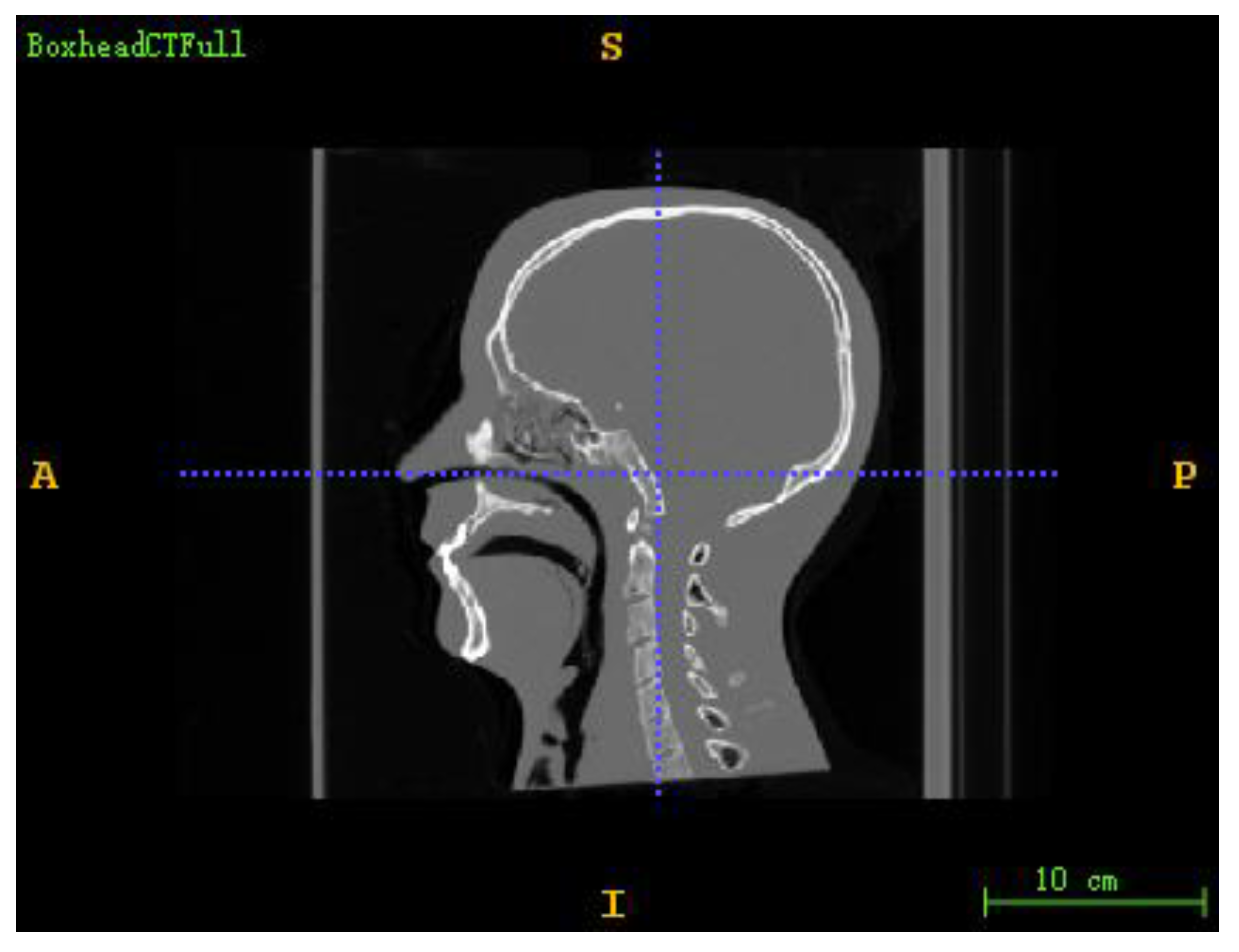
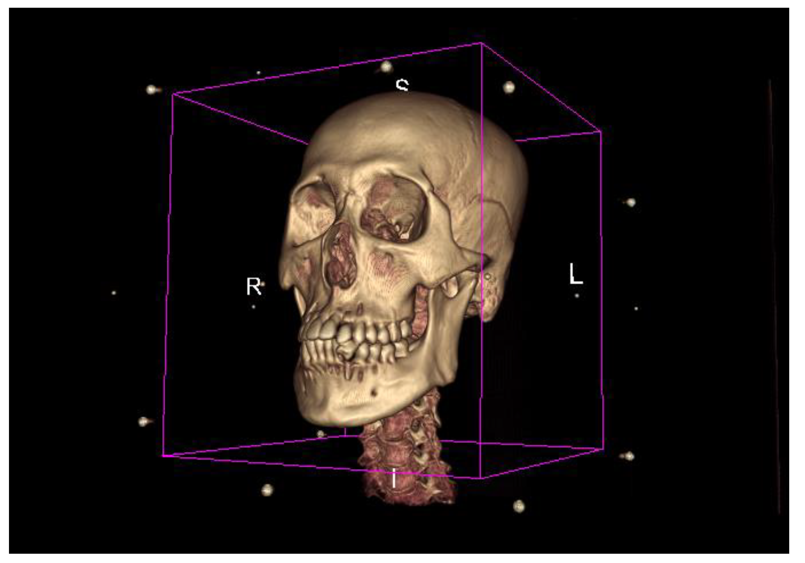
The DICOM sequence obtained from the human brain model’s CT scan is used as a 3D floating image in the registration experiment. The projection image (DRR) under specific CT parameters is used as a 2D reference image to simulate a real X-ray image. The size of the CT image is 512 × 512 × 283, the voxel spacing is 0.7813 × 0.7813 × 1.0, and the unit is mm. The projected image size is 512 × 512, the pixel spacing is 0.5 × 0.5, and the unit is mm. The 3D screenshot of the CT image is shown in Figure 1, and the 3D model rendered by the CT image is shown in Figure 2.
Resampling was carried out on CT images to facilitate the calculation and reduce the amount of experimental calculation. The sampled image data are shown in Table 1. The pixel range of all 2D images in the experiment was linearly mapped to 0–255 through (1).
2.2. Methods
2.2.1. Normalized Cross-Correlation Based on Sobel Operator
In this paper, the normalized cross-correlation based on the Sobel operator (NCCS) is proposed by combining gradient vector angle with normalized cross-correlation [39].
The gradient vectors of the reference image and DRR image at pixel coordinates can be expressed by and , respectively, then the angle between the reference image and DRR image at pixel coordinates can be expressed by (2).
We can achieve the registration by comparing the angle between the reference image and the DRR image. The smaller the angle between the gradient vectors, the more similar the 2D reference image and the DRR image and the more accurate the registration result between the 2D reference image and the 3D floating image. In order to make the angle between gradient vectors and normalized cross-correlation function have the same positive and negative trend, the weight function shown in (3) is adopted.
The range of gradient vector angle is , and the range of is . When the gradient vector angle between the 2D reference image and the DRR image is equal to zero, the registration result is the worst when the two images’ gradient vector angle is equal to zero. Then, the sum of the weight functions at all pixels corresponding to the 2D reference image and DRR image can measure the similarity between the 2D reference image and the DRR image [40], and the position relationship between the 2D reference image and the 3D floating image can be measured, as shown in (4).
The final similarity measure is obtained by multiplying the gradient term with the normalized cross-correlation coefficient. As shown in (5), the gradient information is introduced into the term to enhance the rotation sensitivity by . The optimization process based on the Sobel operator is shown in (6).
2.2.2. Normalized Cross-Correlation Based on LOG Operator
The Gaussian Laplacian can highlight the image’s details by analyzing edge extraction operators while extracting the edge information [41]. This paper proposes combining normalized cross-correlation coefficient with image edge information to overcome the shortcomings of normalized cross-correlation. The Laplacian of Gaussian (LOG) operator extracts image edge information. Normalized cross-correlation (NCCL) based on the LOG operator is obtained. The Laplacian image is obtained by convolution of the reference image and DRR image with the LOG operator. The zero-crossing point in the Laplacian image is no longer needed to obtain the image’s detailed edge. However, two Laplacian images’ consistency is directly measured to use image edge and detail information effectively. This paper uses cosine similarity to measure the similarity between Laplacian images. The new similarity measure composed of normalized cross-correlation coefficient and Gaussian Laplacian operator is shown in (8), and the relationship between and is shown in Equation (9).
The normalized cross-correlation coefficient between the reference image and the DRR image is . The cosine similarity between the Laplacian images is obtained by convolution of the reference image and DRR image with the LOG operator. The optimization process based on the LOG operator can be obtained by substituting Equation (8) into (10). Since the panel’s coordinates are fixed, and NCC and NC are calculated pixel by pixel, both consider the image coordinate information. In addition, the NCC part considers the gray information of the global image. The NC part takes the unique edge information and internal details such as lines and outliers. For medical image registration, the distribution of NCC values is between 0 and 1. The closer the NCC value is to 0, the more significant the difference between the two images. The closer the NCC value is to 1, the stronger the correlation between the two images and the higher the similarity degree is. When the NCC value equals 1, the two images are the same. The value of NC is also distributed between 0 and 1, which has the same meaning as NCC. Therefore, the closer the image registration value is to DR2, the better the image registration effect is.
2.2.3. Multiresolution Strategy
We use the multiresolution strategy to achieve image registration and reduce registration time consumption [42]. A multiresolution registration strategy is a kind of registration technology from coarse to fine, increasing the probability of searching global optimum in parameter space and accelerating the algorithm’s convergence. The basic idea is as follows: first, rough registration is carried out in the case of a low-resolution image, and then the result of low-resolution image registration is taken as the initial value of the next higher resolution image registration, and this step is repeated until the registration reaches the finest scale (original image). This coarse-to-sufficient registration strategy can further improve the image’s robustness by smoothing the low-resolution image.
The multiresolution registration strategy’s key is a multiresolution sampling of the reference image and floating image multiresolution technology. Wavelet transform [43], Laplacian pyramid [44], Gauss pyramid [45], average pyramid, and sampling pyramid are widely studied. This paper needs to obtain low-resolution images from the original high-resolution image, so a Gaussian pyramid in downsampling is used. Compared with the wavelet transform, downsampling can improve the signal-to-noise ratio. In addition, it samples and stores the sampling information of each point signal to improve the registration speed. At the same level, the Gaussian low-pass filter is used to smooth the image to increase the smoothing factor.
Moreover, smoothing in the low-resolution subsampled image can avoid the significant fluctuation of the registration objective function, thus preventing the optimizer from falling into the optimal local value. As a result, the registration algorithm can skip the optimal local value in low-resolution registration. As a result, the success rate of registration is improved. Multiresolution technology has strong robustness to image noise, speeding up the optimization speed and improving the capture range [46,47].
3. Experiments and Results
The environment configuration for this experiment is as follows:
CPU: Intel Core i7-8700K; RAM: 16GB; GPU: Nvidia GeForce RTX 2060S; Operating system: Microsoft Windows 10; Development tools: Microsoft Visual Studio2015; Development language: Microsoft C++.
3.1. Experiment Process
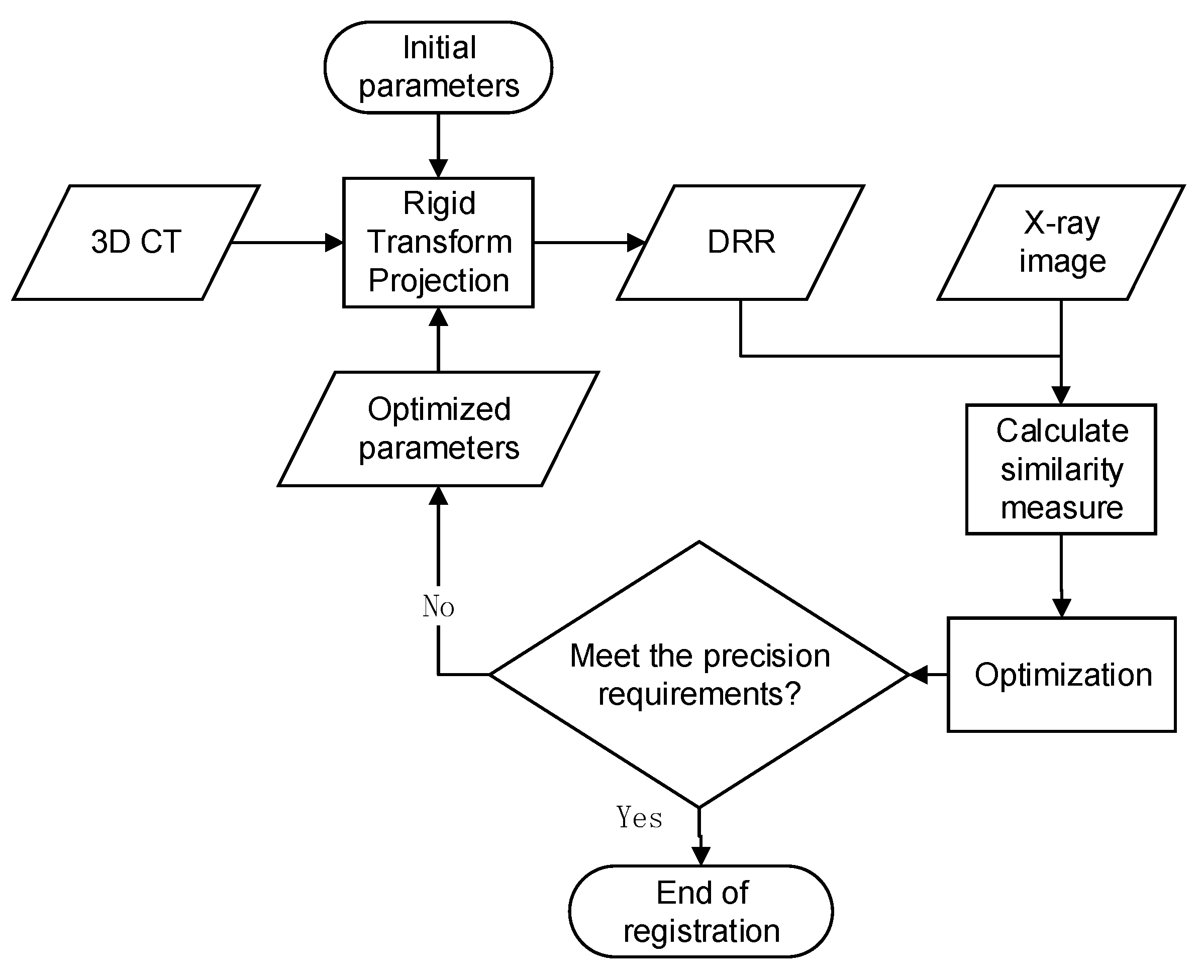
In this paper, the image pyramid is divided into three levels: the shrinkage factor of the first level is 4, the second level is 2, and the third level is 1. Each layer is the standard single-resolution image registration. Firstly, the CT image is transformed according to the initial space transformation parameters. Since this paper is for the human brain model registration, the rigid transformation model is adopted. Then, the DRR image is generated by the projection of the CT image. First, the projection threshold is set to 0 to obtain the DRR image, mainly composed of bone information. Next, the similarity measure between the DRR and reference images is calculated. After taking the similarity measure as the objective function, the Powell Brent optimization algorithm optimizes the space transformation parameters until the iteration stop condition, stop registration, and output space transformation parameters are reached. The flow chart of image registration is shown in Figure 3.
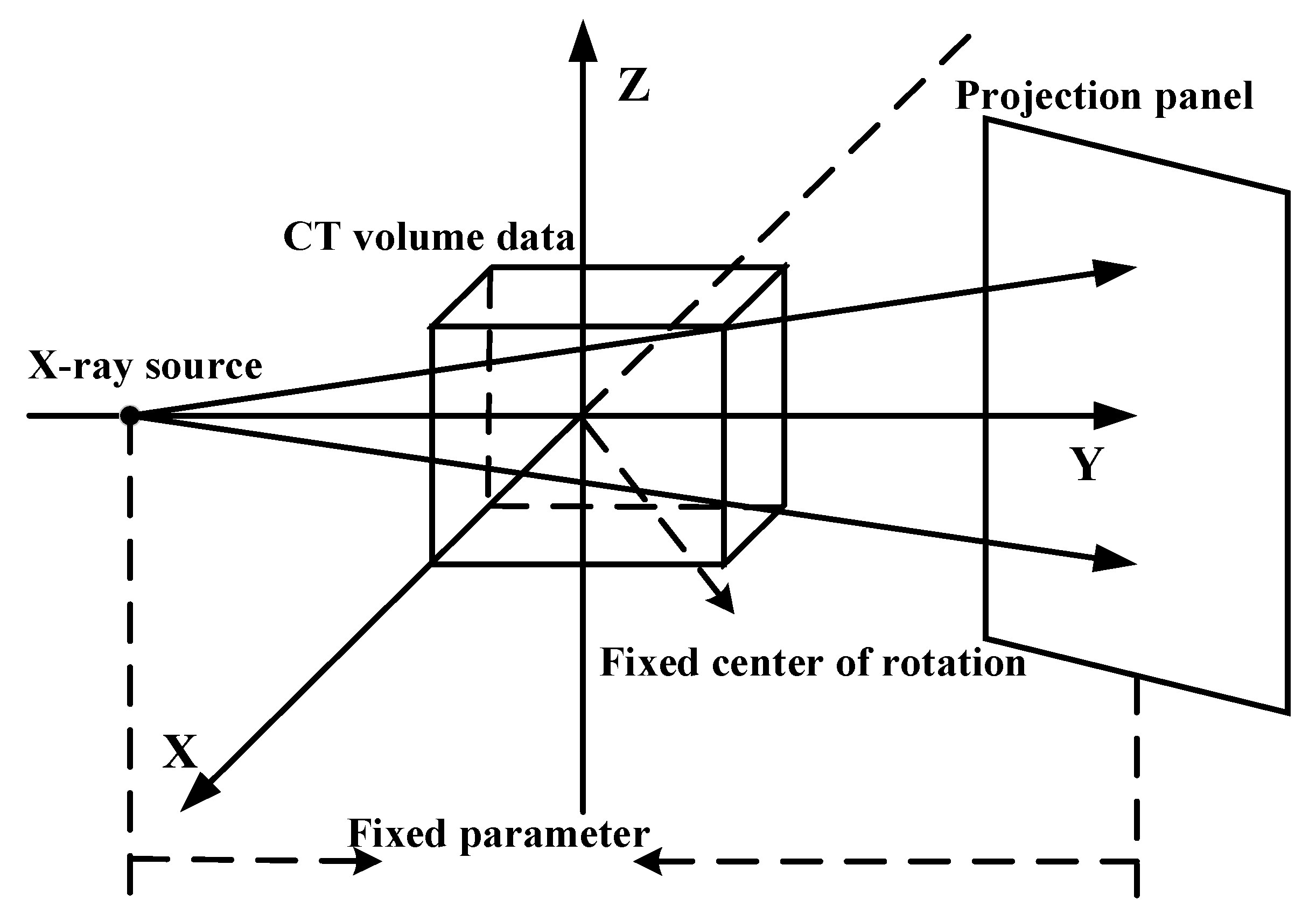
In CT image projection, the traditional ray casting algorithm is inefficient and not conducive to registration experiments. Therefore, a fast Siddon Jacobs ray tracing algorithm is adopted [48,49]. The algorithm sums up the iterative formula of ray path according to the geometric law. According to the formula, it then calculates the intersection point of ray and voxel space. The Siddon Jacobs algorithm is at least one order of magnitude faster than the ray tracing algorithm based on linear interpolation. Before using the projection algorithm, it is necessary to establish the projection coordinate system, that is, the coordinate registration system. In this paper, the coordinate system, as shown in Figure 4, is designed. Since the patient is almost in the X-ray field center when taking X-ray images, the center of initial CT volume data is set at the coordinate system’s origin. The coordinate system is established according to the direction of CT volume data. The projection panel is located on both sides of CT volume data. This projection coordinate system is similar to the real shooting scene. The standard LPS (left poster superior) coordinate system can reduce the calculation [50,51]. In practical application, if the CT image is used to register with the real X-ray image, when the X-ray imaging coordinate parameters are unknown, it is necessary to calibrate the X-ray image to determine the relevant parameters of the projection coordinate system.
3.2. Experimental Evaluation Criteria
In this paper, the difference between the images after registration is selected for qualitative analysis, and repeated registration experiments are carried out. Furthermore, the mean absolute error (MAE) [52], target registration error (MTRE) [53], and iteration time are selected for quantitative analysis. The registration is considered successful when the errors of rotation and translation parameters are less than 5.
MSE is represented by Equation (10), and MAE is represented by Equation (11).
The original normalized cross-correlation (NCC) algorithm is used as the registration experimental control group to verify the effectiveness and accuracy of the normalized cross-correlation algorithm with the Sobel operator (NCCS) and the normalized cross-correlation algorithm with the LOG operator (NCCL). The experiments are divided into two categories. The first one is to register the original single-resolution image directly. The second is to use a multiresolution strategy for registration.
The Powell optimization algorithm’s one-dimensional search accuracy in the experiment is set to 0.01. The algorithm’s overall iterative accuracy is set to 0.001, and the maximum number of iterations is set to 1000. For the original resolution image registration, three groups of experiments are set up, and the rigid body transformation parameters are arranged according to the order . The first three parameters are rotation along the X-, Y-, and Z-axes. The last three parameters are translation along the X-, Y-, and Z-axes. The true values of the first group of experimental reference images are set to (−3,4,2,5,5,5). The second group of experimental reference images is set to (−3,4,2,10,10,10). Finally, the third group of experimental reference images is set to (5,6,7,8,9,10). In the experiment, the initial value is optimized by (0,0,0,0,0,0). As shown in Figure 5, the DRR image projected by CT at the initial value is shown. The reference images of the three groups of experiments are shown in Figure 6a–c and correspond to the reference images of experiment 1, experiment 2, and experiment 3, respectively.
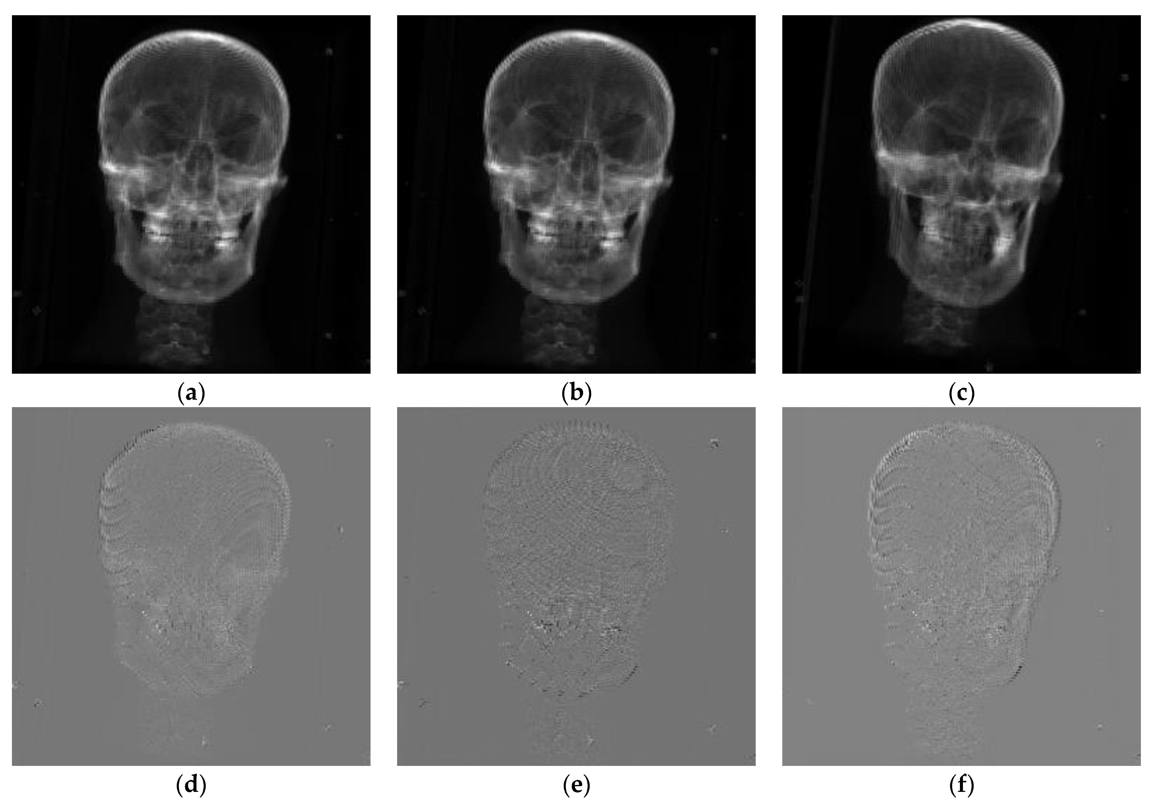
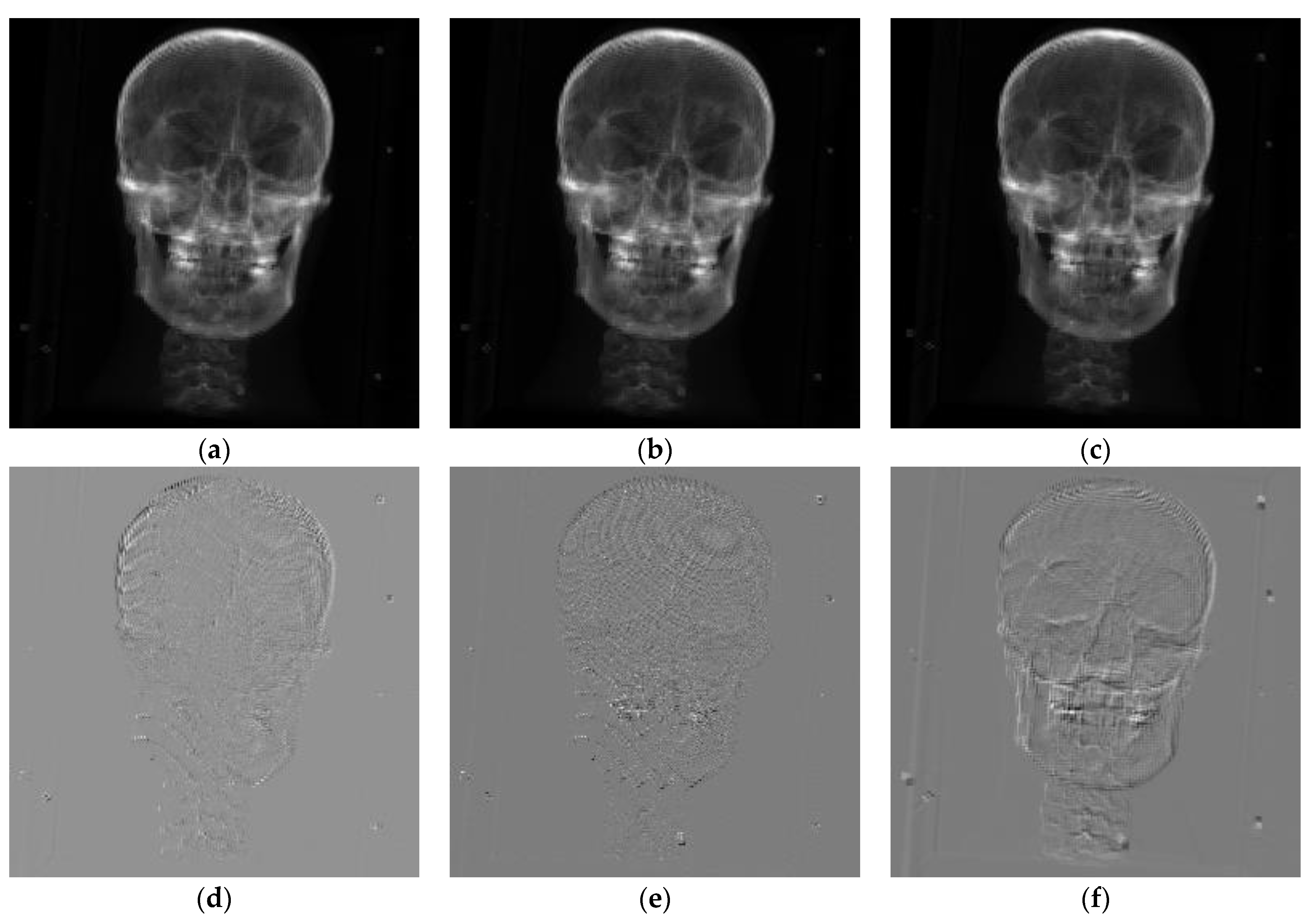
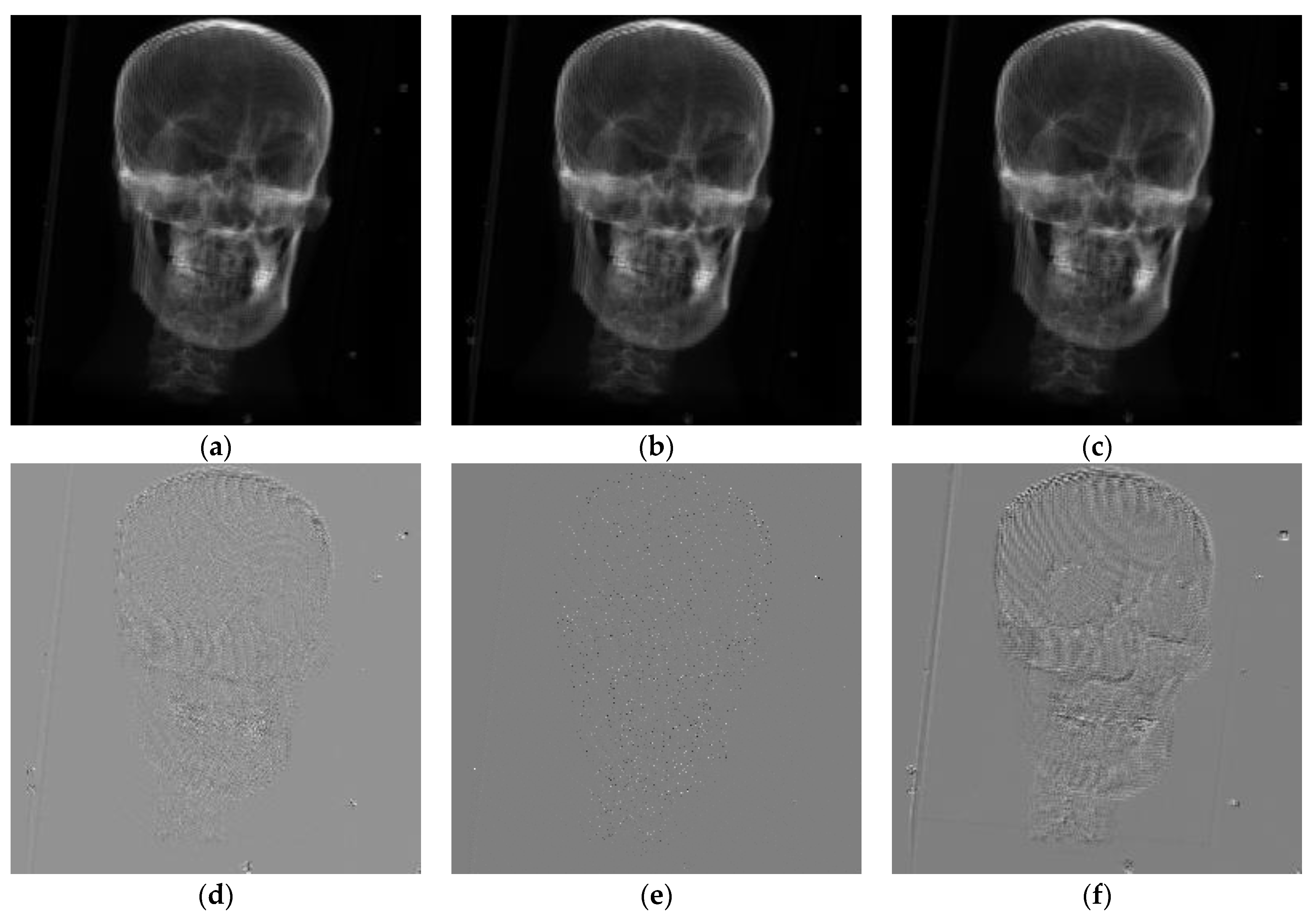
The results of the first group of experiments are shown in Figure 7. The second group of experimental results is shown in Figure 8, and the third group of experiments is shown in Figure 9. NCCS represents normalized cross-correlation based on the Sobel operator. NCCL represents normalized cross-correlation based on the LOG operator, and NCC represents normalized cross-correlation. Each result display chart is divided into two rows and three columns for comparative analysis of registration results. The first line represents the DRR image generated by CT projection after registration. The second line represents the difference between the reference image and the registered DRR image. The first column corresponds to the normalized cross-correlation based on the Sobel operator from top to bottom. The second column corresponds to the normalized cross-correlation based on the LOG operator. The third column corresponds to the original normalized cross-correlation. The different images of the three experiments show that the difference image is the smoothest when NCC based on the LOG operator is used as the similarity measure. The difference between the registration result and the reference image is the smallest; NCC’s registration effect based on the Sobel operator is the second. The difference between the original NCC algorithm and the reference image is the largest. The NCC based on the LOG operator is the largest. The registration results are similar to those obtained by NCC based on the Sobel operator.
Next, we will verify the experimental results by quantitative statistical analysis of the registration results.
The three rotation parameters of the optimized initial value are selected within degrees for the true value point of for the rigid body transformation. The sampling unit is 5 degrees to analyze the performance difference between the original normalized cross-correlation and the improved normalized cross-correlation. The three translation parameters of the optimized initial value are selected within mm and 5 mm as the sampling unit. MAE, MTRE, and time are taken as the measurement indexes. MAE and MTRE are calculated as the average of multiple tests.
The statistics of registration results of the three similarity measures are shown in Table 2. NCC represents normalized cross-correlation. NCCS represents normalized cross-correlation based on the Sobel operator. Finally, NCCL represents normalized cross-correlation based on the LOG operator.
In order to verify the influence of the Sobel operator and LOG operator on the convergence region of the normalized cross-correlation algorithm, is used as the initial value point of rigid body transformation. However, the sampling space of the rotation parameter truth-value point is expanded to [−40,40] degrees. Furthermore, the sampling space of translation parameter true-value point is expanded to [−40,40] mm. The experimental results are shown in Table 3. The data of the two experiments are recorded in the table.
3.3. Multiresolution Registration Experiment
This paper introduces the multiresolution strategy to realize the registration step by step from coarse to fine to speed up the registration algorithm’s convergence speed and improve the registration efficiency. At each registration experiment level, the Powell optimization algorithm’s one-dimensional search accuracy is set to 0.01. The algorithm’s overall iterative accuracy is set to 0.001, and the maximum number of iterations is set to 1000. The rigid-body transformation parameters are arranged in . The first three parameters are rotation along the X-, Y-, and Z-axes, and the last three are translation along the X-, Y-, and Z-axes. The experimental results show that when the initial value is optimized, the true value point of the rotation parameter is and is sampled within degrees. Likewise, the true value point of the translation parameter is sampled within mm.
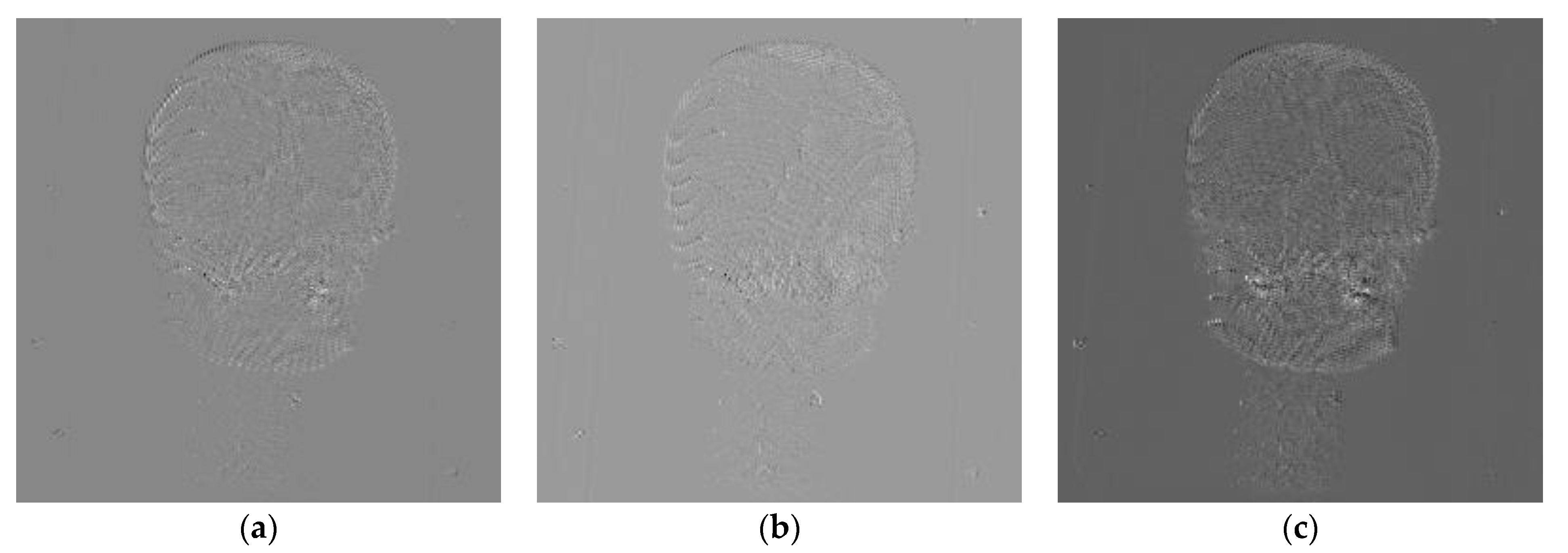
Figure 10 shows the difference image between CT and DRR image registration results under the multiresolution framework. The true value image is shown as . NCC’s true value points are based on the Sobel operator, NCC based on LOG operator, and original NCC from left to right.
Table 4 shows the statistical registration results of the three similarity measures under the multiresolution registration framework.
4. Discussion
From the intuitive comparison of the three experiments, it can be concluded that after introducing gradient information or edge information, the registration performance of the new normalized correlation is significantly improved compared with the original normalized cross-correlation. Furthermore, from the perspective of image qualitative analysis, the improved normalized cross-correlation based on the LOG operator is better than that of the Sobel operator. Finally, we will verify the above conclusion through the quantitative statistical analysis of the registration results.
From the statistical results, when CT and DRR simulated X-ray images are registered, the average values of MTRE and MAE of NCC based on the LOG operator are significantly improved compared with the original NCC. NCC’s performance based on the Sobel operator is also improved compared with the original NCC in MTRE and MAE’s mean value. It is smaller than the NCC based on the Sobel operator, but the gap is smaller. NCC’s registration time based on the Sobel operator or LOG operator is longer than that of the original NCC. This is because the two improved algorithms need to extract image features through the Sobel operator or LOG operator while calculating the original NCC. Each iteration of the rigid body transformation parameter update needs to re-extract features. However, due to NCC calculation and feature extraction’s sequential execution, unnecessary time waste can be caused. Hence, the registration time gap can be further reduced by optimizing the code.
According to the results in Table 2, when the translation parameter is small and the rotation parameter reaches 40 degrees, both the original NCC and the log-based NCC cannot achieve accurate registration. In contrast, the NCC based on the Sobel operator can still achieve enough registration accuracy. However, the accuracy is slightly reduced compared with the registration experiment with a small angle. When the rotation parameter is small and the translation parameter reaches 40 mm, NCC registration based on the Sobel operator can still be achieved within acceptable accuracy compared with the original NCC and LOG operator. Compared with the original NCC experiment, the larger the difference between the true value point and the initial value point in the rotation parameters, the more difficult it is to approach the true value. This is because the order of rigid body transformation is rotation first and then translation. NCC is more sensitive to translation, so it is challenging to ensure rotation accuracy, limiting the translation’s accuracy. The improved Sobel operator increases the algorithm’s sensitivity to the rotation, thus increasing NCC’s convergence range.
To sum up, introducing edge information through the LOG operator or introducing angle information of the gradient vector through the Sobel operator can reduce the registration indexes MAE and MTRE of normalized cross-correlation. Both can improve registration accuracy and registration stability. The LOG operator’s edge information can significantly improve the normalized cross-correlation as far as the registration accuracy is concerned. However, the gradient vector’s angle information introduced by the Sobel operator can increase the NCC measure’s sensitivity to rotation transformation to improve the registration accuracy and increase the convergence range of the algorithm. The multiresolution strategy can accelerate the convergence speed of registration, which is very beneficial to improve registration efficiency. However, the multiresolution strategy does not affect the convergence region of registration. Sometimes, it will lead the registration process to fall into local optimization. The registration may not be successful if the parameter settings of the optimizer are changed. This shows that the multiresolution registration depends on the parameter setting of the optimizer.
5. Conclusions
This paper introduces a 2D/3D medical image registration method based on normalized cross-correlation. It analyzes the advantages and disadvantages of normalized cross-correlation. It is only suitable for small-angle rotation. The registration accuracy is relatively low to solve the normalized cross-correlation algorithm only using global gray information. An improved normalized cross-correlation algorithm is proposed. Based on the LOG operator’s improvement, based on the original normalized cross-correlation, the cosine similarity of linear combination Laplacian of Gaussian operators is proposed. The operator increases the edge information and the internal details such as outliers and lines. Based on the improvement of the Sobel operator, the angle of the gradient vector is introduced. The sum of the gradient vector angle’s weight function is multiplied by normalized cross-correlation to increase the rotation transformation’s sensitivity to improve the accuracy and the convergence region. The multiresolution algorithm is adopted to aim at the computational efficiency problem caused by the normalized cross-correlation algorithm. The experimental results show that the improved normalized cross-correlation has higher registration accuracy. The multiresolution strategy can reduce the registration algorithm’s initial value sensitivity and reduce the algorithm’s probability of falling into the local optimum.
This experiment can be improved in the future. In the optimization process of iterative 2D/3D medical image registration, DRR images need to be generated continuously through projection rendering, which will lead to a lot of time consumption. Furthermore, the DRR projection belongs to graphics rendering, so we can consider using a GPU to accelerate the DRR projection process and improve the algorithm’s calculation speed. This study assumes that only rigid body transformation is performed on 3D images. However, in clinical application, some tissues of the human body and between bones will deform to a certain extent. Therefore, 2D/3D registration based on rigid body transformation cannot fully meet the clinical needs. More complex deformation registration problems can be studied in the future.
Author Contributions
Conceptualization, W.Z. and B.Y.; methodology, B.Y. and S.L.; software, Y.W. and J.T.; validation, Y.W., J.T. and B.Y.; formal analysis, W.Z.; investigation, J.T.; resources, W.Z.; data curation, Y.W.; writing—original draft preparation, Y.W. and L.Y.; writing—review and editing, W.Z. and S.L.; visualization, Y.W. and S.L.; supervision, S.L.; project administration, B.Y.; funding acquisition, W.Z. All authors have read and agreed to the published version of the manuscript.
Funding
This work was jointly supported by the Sichuan Science and Technology Program (2021YFQ0003).
Institutional Review Board Statement
Not applicable.
Informed Consent Statement
Not applicable.
Data Availability Statement
The data presented in this study are available on request from the corresponding author. The data are not publicly available in their current status due to the request of the production team.
Conflicts of Interest
The authors declare that they have no known competing financial interests or personal relationships that could have appeared to influence the work reported in this paper.
References
- Alam, F.; Rahman, S.U.; Ullah, S.; Gulati, K. Medical image registration in image guided surgery: Issues, challenges and research opportunities. Biocybern. Biomed. Eng. 2018, 38, 71–89. [Google Scholar] [CrossRef]
- Chen, X.; Yin, L.; Fan, Y.; Song, L.; Ji, T.; Liu, Y.; Tian, J.; Zheng, W. Temporal evolution characteristics of PM 2.5 concentration based on continuous wavelet transform. Sci. Total Environ. 2020, 699, 134244. [Google Scholar] [CrossRef] [PubMed]
- Ni, X.; Yin, L.; Chen, X.; Liu, S.; Yang, B.; Zheng, W. Semantic representation for visual reasoning. MATEC Web Conf. 2019, 277, 02006. [Google Scholar] [CrossRef]
- Otake, Y.; Armand, M.; Armiger, R.S.; Kutzer, M.D.; Basafa, E.; Kazanzides, P.; Taylor, R.H. Intraoperative image-based multiview 2D/3D registration for image-guided orthopaedic surgery: Incorporation of fiducial-based C-arm tracking and GPU-acceleration. IEEE Trans. Med. Imaging 2011, 31, 948–962. [Google Scholar] [CrossRef] [Green Version]
- Steininger, P.; Neuner, M.; Fritscher, K.; Sedlmayer, F.; Deutschmann, H. A Novel Class of Machine-Learning-Driven Real-Time 2D/3D Tracking Methods: Texture Model Registration (TMR). In Proceedings of the Medical Imaging 2011: Visualization, Image-Guided Procedures, and Modeling. International Society for Optics and Photonics, Lake Buena Vista, FL, USA, 12–17 February 2011; p. 79640G. [Google Scholar]
- Cleary, K.; Peters, T.M. Image-guided interventions: Technology review and clinical applications. Annu. Rev. Biomed. Eng. 2010, 12, 119–142. [Google Scholar] [CrossRef]
- Fu, D.; Kuduvalli, G. A fast, accurate, and automatic 2D–3D image registration for image-guided cranial radiosurgery. Med. Phys. 2008, 35, 2180–2194. [Google Scholar] [CrossRef]
- Markelj, P.; Tomaževič, D.; Pernuš, F.; Likar, B. Optimizing bone extraction in MR images for 3D/2D gradient based registration of MR and X-ray images. In Proceedings of the Medical Imaging 2007: Image Processing. International Society for Optics and Photonics, San Diego, CA, USA, 17–22 February 2007; p. 651224. [Google Scholar]
- Ding, Y.; Tian, X.; Yin, L.; Chen, X.; Liu, S.; Yang, B.; Zheng, W. Multi-scale Relation Network for Few-Shot Learning Based on Meta-learning. In International Conference on Computer Vision Systems; Springer: Cham, Switzerland, 2019; pp. 343–352. [Google Scholar]
- Liu, S.; Gao, Y.; Zheng, W.; Li, X. Performance of two neural network models in bathymetry. Remote Sens. Lett. 2015, 6, 321–330. [Google Scholar] [CrossRef]
- Liu, X.; Zheng, W.; Mou, Y.; Li, Y.; Yin, L. Microscopic 3D reconstruction based on point cloud data generated using defocused images. Meas. Control 2021, 54, 1309–1318. [Google Scholar] [CrossRef]
- Xu, C.; Yang, B.; Guo, F.; Zheng, W.; Poignet, P. Sparse-view CBCT reconstruction via weighted Schatten p-norm minimization. Opt. Express 2020, 28, 35469–35482. [Google Scholar] [CrossRef]
- Yang, B.; Liu, C.; Zheng, W.; Liu, S.; Huang, K. Reconstructing a 3D heart surface with stereo-endoscope by learning eigen-shapes. Biomed. Opt. Express 2018, 9, 6222–6236. [Google Scholar] [CrossRef] [Green Version]
- Aouadi, S.; Sarry, L. Accurate and precise 2D–3D registration based on X-ray intensity. Comput. Vis. Image Underst. 2008, 110, 134–151. [Google Scholar] [CrossRef]
- Tang, Y.; Liu, S.; Deng, Y.; Zhang, Y.; Yin, L.; Zheng, W. Construction of force haptic reappearance system based on Geomagic Touch haptic device. Comput. Methods Programs Biomed. 2020, 190, 105344. [Google Scholar] [CrossRef] [PubMed]
- Tang, Y.; Liu, S.; Deng, Y.; Zhang, Y.; Yin, L.; Zheng, W. An improved method for soft tissue modeling. Biomed. Signal Process. Control 2021, 65, 102367. [Google Scholar] [CrossRef]
- Yang, B.; Liu, C.; Huang, K.; Zheng, W. A triangular radial cubic spline deformation model for efficient 3D beating heart tracking. Signal Image Video Process. 2017, 11, 1329–1336. [Google Scholar] [CrossRef] [Green Version]
- Yang, B.; Liu, C.; Zheng, W.; Liu, S. Motion prediction via online instantaneous frequency estimation for vision-based beating heart tracking. Inf. Fusion 2017, 35, 58–67. [Google Scholar] [CrossRef]
- Yang, B.; Liu, C.; Zheng, W. PCA-based 3D pose modeling for beating heart tracking. In Proceedings of the 2017 13th International Conference on Natural Computation, Fuzzy Systems and Knowledge Discovery (ICNC-FSKD), Guilin, China, 29–31 July 2017; pp. 586–590. [Google Scholar] [CrossRef]
- Zheng, W.; Li, X.; Yin, L.; Wang, Y. The retrieved urban LST in Beijing based on TM, HJ-1B and MODIS. Arab. J. Sci. Eng. 2016, 41, 2325–2332. [Google Scholar] [CrossRef]
- Yang, B.; Cao, T.; Zheng, W. Beating heart motion prediction using iterative optimal sine filtering. In Proceedings of the 2017 10th International Congress on Image and Signal Processing, BioMedical Engineering and Informatics (CISP-BMEI), Shanghai, China, 14–16 October 2017; pp. 1–5. [Google Scholar] [CrossRef]
- Zhou, Y.; Zheng, W.; Shen, Z. A New Algorithm for Distributed Control Problem with Shortest-Distance Constraints. Math. Probl. Eng. 2016, 2016, 1604824. [Google Scholar] [CrossRef]
- Goitein, M.; Abrams, M.; Rowell, D.; Pollari, H.; Wiles, J. Multi-dimensional treatment planning: II. Beam’s eye-view, back projection, and projection through CT sections. Int. J. Radiat. Oncol. Biol. Phys. 1983, 9, 789–797. [Google Scholar] [CrossRef]
- Mu, Z. A fast DRR generation scheme for 3D-2D image registration based on the block projection method. In Proceedings of the IEEE Conference on Computer Vision and Pattern Recognition Workshops, Las Vegas, NV, USA, 26 June–1 July 2016; pp. 169–177. [Google Scholar]
- Ghafurian, S.; Hacihaliloglu, I.; Metaxas, D.N.; Tan, V.; Li, K. A computationally efficient 3D/2D registration method based on image gradient direction probability density function. Neurocomputing 2017, 229, 100–108. [Google Scholar] [CrossRef]
- Pan, H.; Zhou, C.; Zhu, Q.; Zheng, D. A fast registration from 3D CT images to 2D X-ray images. In Proceedings of the 2018 IEEE 3rd International Conference on Big Data Analysis (ICBDA), Shanghai, China, 9–12 March 2018; pp. 351–355. [Google Scholar]
- Zheng, G.; Zhang, X.; Jonić, S.; Thévenaz, P.; Unser, M.; Nolte, L.-P. Point similarity measures based on MRF modeling of difference images for spline-based 2D-3D rigid registration of X-ray fluoroscopy to CT images. In International Workshop on Biomedical Image Registration; Springer: Cham, Switzerland, 2006; pp. 186–194. [Google Scholar]
- Zheng, J.; Miao, S.; Liao, R. Learning CNNS with pairwise domain adaption for real-time 6dof ultrasound transducer detection and tracking from X-ray images. In International Conference on Medical Image Computing and Computer-Assisted Intervention; Springer: Cham, Switzerland, 2017; pp. 646–654. [Google Scholar]
- Dorgham, O.M.; Laycock, S.D.; Fisher, M.H. GPU accelerated generation of digitally reconstructed radiographs for 2-D/3-D image registration. IEEE Trans. Biomed. Eng. 2012, 59, 2594–2603. [Google Scholar] [CrossRef]
- Zheng, J.; Miao, S.; Wang, Z.J.; Liao, R. Pairwise domain adaptation module for CNN-based 2-D/3-D registration. J. Med. Imaging 2018, 5, 021204. [Google Scholar] [CrossRef] [PubMed]
- Liao, R.; Miao, S.; de Tournemire, P.; Grbic, S.; Kamen, A.; Mansi, T.; Comaniciu, D. An artificial agent for robust image registration. In Proceedings of the AAAI Conference on Artificial Intelligence, San Francisco, CA, USA, 4–9 February 2017. [Google Scholar]
- Miao, S.; Piat, S.; Fischer, P.; Tuysuzoglu, A.; Mewes, P.; Mansi, T.; Liao, R. Dilated fcn for multi-agent 2D/3D medical image registration. In Proceedings of the AAAI Conference on Artificial Intelligence, New Orleans, LA, USA, 2–7 February 2018. [Google Scholar]
- Miao, S.; Wang, Z.J.; Liao, R. A CNN regression approach for real-time 2D/3D registration. IEEE Trans. Med. Imaging 2016, 35, 1352–1363. [Google Scholar] [CrossRef] [PubMed]
- Toth, D.; Miao, S.; Kurzendorfer, T.; Rinaldi, C.A.; Liao, R.; Mansi, T.; Rhode, K.; Mountney, P. 3D/2D model-to-image registration by imitation learning for cardiac procedures. Int. J. Comput. Assist. Radiol. Surg. 2018, 13, 1141–1149. [Google Scholar] [CrossRef] [PubMed] [Green Version]
- Valenti, M.; Ferrigno, G.; Martina, D.; Yu, W.; Zheng, G.; Shandiz, M.A.; Anglin, C.; De Momi, E. Gaussian mixture models based 2D–3D registration of bone shapes for orthopedic surgery planning. Med. Biol. Eng. Comput. 2016, 54, 1727–1740. [Google Scholar] [CrossRef]
- Wang, Y.; Yu, Q.; Yu, W. An improved Normalized Cross Correlation algorithm for SAR image registration. In Proceedings of the 2012 IEEE International Geoscience and Remote Sensing Symposium, Munich, Germany, 22–27 July 2012; pp. 2086–2089. [Google Scholar]
- Heo, Y.S.; Lee, K.M.; Lee, S.U. Robust Stereo Matching Using Adaptive Normalized Cross-Correlation. IEEE Trans. Pattern Anal. Mach. Intell. 2011, 33, 807–822. [Google Scholar] [CrossRef] [Green Version]
- Johnson, H.; McCormick, M.; Ibanez, L. The ITK Software Guide Book 2: Design and Functionality—Volume 2; Kitware. Inc.: Clifton Park, NY, USA, 2015. [Google Scholar]
- Kaso A Computation of the normalized cross-correlation by fast Fourier transform. PLoS ONE 2018, 13, e0203434. [CrossRef]
- Zhang, Z.; Wang, L.; Zheng, W.; Yin, L.; Hu, R.; Yang, B. Endoscope image mosaic based on pyramid ORB. Biomed. Signal Process. Control 2022, 71, 103261. [Google Scholar] [CrossRef]
- Eresen, A.; Birch, S.M.; Alic, L.; Griffin, J.F.; Kornegay, J.N.; Ji, J.X. New similarity metric for registration of MRI to histology: Golden retriever muscular dystrophy imaging. IEEE Trans. Biomed. Eng. 2018, 66, 1222–1230. [Google Scholar] [CrossRef]
- Guo, F.; Yang, B.; Zheng, W.; Liu, S. Power Frequency Estimation Using Sine Filtering of Optimal Initial Phase. Measurement 2021, 186, 110165. [Google Scholar] [CrossRef]
- Liu, S.; Wei, X.; Zheng, W.; Yang, B. A Four-channel Time Domain Passivity Approach for Bilateral Teleoperator. In Proceedings of the 2018 IEEE International Conference on Mechatronics and Automation (ICMA), Changchun, China, 5–8 August 2018; pp. 318–322. [Google Scholar] [CrossRef]
- Lai, W.; Huang, J.; Ahuja, N.; Yang, M. Fast and Accurate Image Super-Resolution with Deep Laplacian Pyramid Networks. IEEE Trans. Pattern Anal. Mach. Intell. 2019, 41, 2599–2613. [Google Scholar] [CrossRef] [Green Version]
- Wang, Y.; Tian, J.; Liu, Y.; Yang, B.; Liu, S.; Yin, L.; Zheng, W. Adaptive Neural Network Control of Time Delay Teleoperation System Based on Model Approximation. Sensors 2021, 21, 7443. [Google Scholar] [CrossRef] [PubMed]
- Nasihatkon, B.; Kahl, F. Multiresolution Search of the Rigid Motion Space for Intensity-Based Registration. IEEE Trans. Pattern Anal. Mach. Intell. 2017, 40, 179–191. [Google Scholar] [CrossRef] [PubMed] [Green Version]
- Shao, Z.; Han, J.; Liang, W.; Tan, J.; Guan, Y. Robust and fast initialization for intensity-based 2D/3D registration. Adv. Mech. Eng. 2014, 6, 989254. [Google Scholar] [CrossRef]
- Jacobs, F.; Sundermann, E.; De Sutter, B.; Christiaens, M.; Lemahieu, I. A fast algorithm to calculate the exact radiological path through a pixel or voxel space. J. Comput. Inf. Technol. 1998, 6, 89–94. [Google Scholar]
- Siddon, R.L. Fast calculation of the exact radiological path for a three-dimensional CT array. Med. Phys. 1985, 12, 252–255. [Google Scholar] [CrossRef]
- Hurvitz, A.; Joskowicz, L. Registration of a CT-like atlas to fluoroscopic X-ray images using intensity correspondences. Int. J. Comput. Assist. Radiol. Surg. 2008, 3, 493–504. [Google Scholar] [CrossRef]
- Pei-fenga, J.; Anb, Q.; Wei-donga, Z.; Juna, O.; Mei-chaoa, Z.; Ji-honga, F.; Shi-zhena, Z.; Jian-yia, L. 2D/3D registration system based on single X-ray image and CT data. J. Med. Biomech. 2010, 67, 101815. [Google Scholar]
- Zhang, Z.; Liu, Y.; Tian, J.; Liu, S.; Yang, B.; Xiang, L.; Yin, L.; Zheng, W. Study on Reconstruction and Feature Tracking of Silicone Heart 3D Surface. Sensors 2021, 21, 7570. [Google Scholar] [CrossRef]
- Li, Y.; Zheng, W.; Liu, X.; Mou, Y.; Yin, L.; Yang, B. Research and improvement of feature detection algorithm based on FAST. Rend. Lincei. Sci. Fis. Nat. 2021, 32, 775–789. [Google Scholar] [CrossRef]
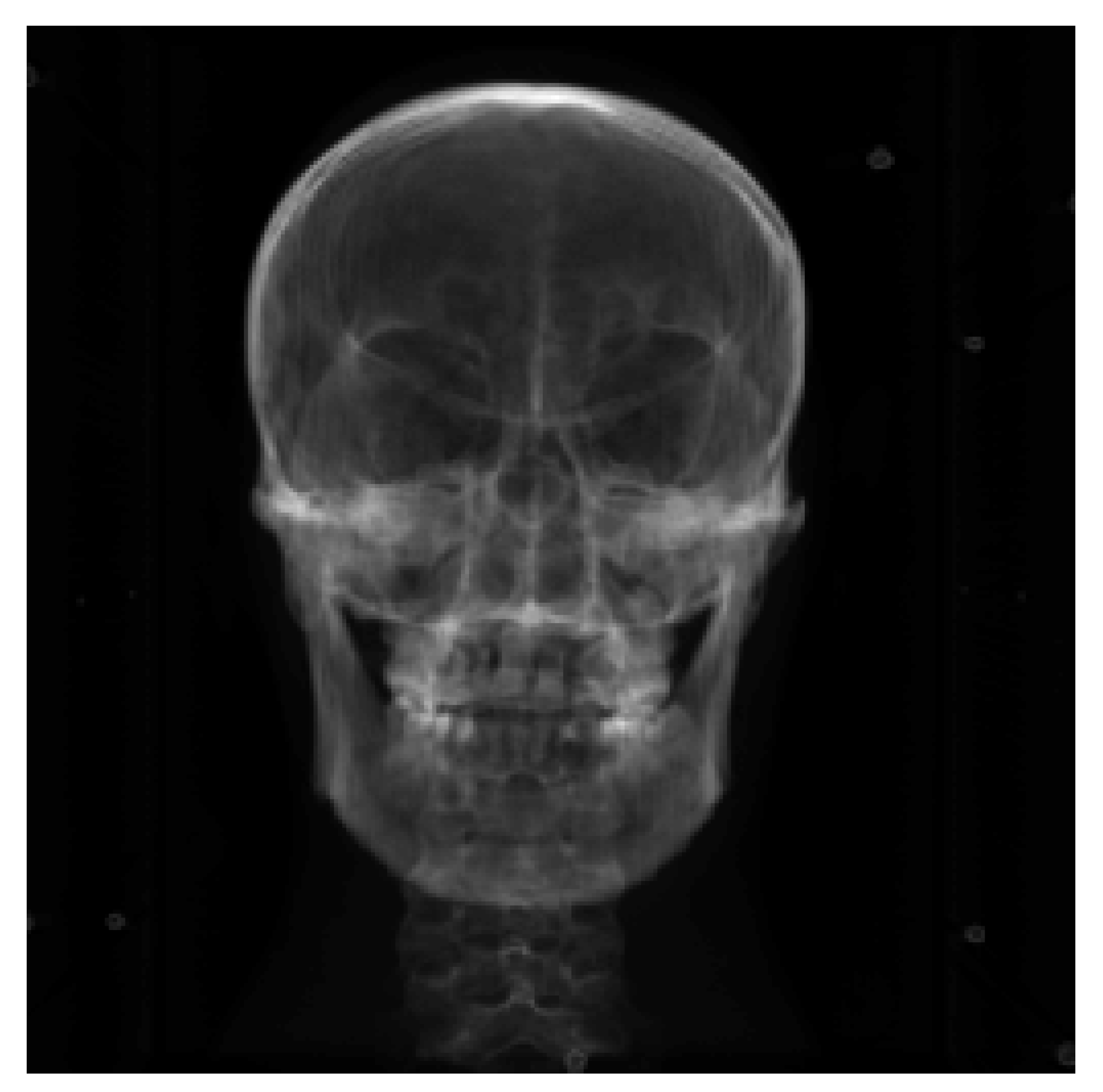
Figure 1.
Three dimensional CT of the brain model.

Figure 2.
CT rendering of the brain model.

Figure 3.
Image registration flow chart.

Figure 4.
Schematic diagram of projection coordinate system.

Figure 5.
DRR image at the initial value.

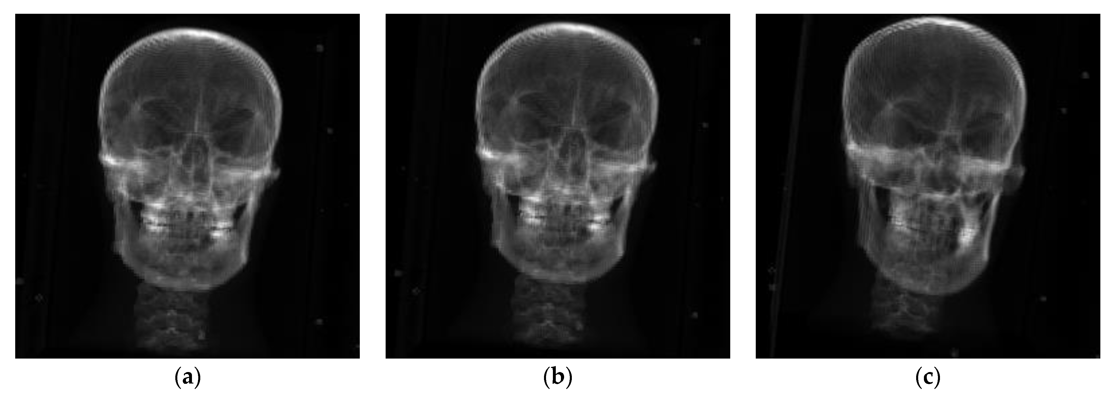
Figure 6.
Experimental reference images. (a) Experiment 1 reference image; (b) experiment 2 reference image; (c) experiment 3 reference image.
Figure 6.
Experimental reference images. (a) Experiment 1 reference image; (b) experiment 2 reference image; (c) experiment 3 reference image.

Figure 7.
Experimental results of group 1. (a) DRR based on NCCS registration; (b) DRR after NCCL registration; (c) DRR based on NCC registration; (d) difference map after registration based on NCCS; (e) difference map after registration based on NCCL; (f) difference map after registration based on NCC.

Figure 8.
Experimental results of group 2. (a) DRR based on NCCS registration; (b) DRR based on NCCL registration; (c) DRR after registration based on NCC; (d) difference map after registration based on NCCS; (e) difference map after registration based on NCCL; (f) difference map after registration based on NCC.

Figure 9.
Experimental results of group 3. (a) DRR based on NCCS registration; (b) DRR based on NCCL registration; (c) DRR after registration based on NCC; (d) difference map after registration based on NCCS; (e) difference map after registration based on NCCL; (f) difference map after registration based on NCC.

Figure 10.
Multiresolution registration difference image. (a) Based on NCCS registration difference image; (b) based on NCCL registration difference image; (c) based on NCC registration difference image.
Figure 10.
Multiresolution registration difference image. (a) Based on NCCS registration difference image; (b) based on NCCL registration difference image; (c) based on NCC registration difference image.


Table 1.
Related parameters of image registration.
| Data | Size | Spacing (mm) | Pixel Range |
|---|---|---|---|
| CT image | 200 × 200 × 142 | 2 × 2 × 2 | −1024~2976 |
| Analog X-ray image (DRR) | 256 × 256 | 1 × 1 | 0~255 |
Table 2.
Single-resolution experimental results.
| Rotation (°) | Translation (mm) | ||
|---|---|---|---|
| NCCS | MAE | 0.4955 | 0.9883 |
| MTRE | 1.94117 mm | ||
| time | 6012.6 s | ||
| NCCL | MAE | 0.3189 | 0.7750 |
| MTRE | 1.4759 mm | ||
| time | 5765.6 s | ||
| NCC | MAE | 1.2083 | 1.4079 |
| MTRE | 3.19295 mm | ||
| time | 5129 s | ||
Table 3.
Experimental results of single resolution with enlarged sampling space.
| (α, β, θ, tx, ty, tz) | ||
|---|---|---|
| Truth point | (10,10,10,40,40,40) | (40,40,40,10,10,10) |
| Initial value point | (0,0,0,0,0,0) | (0,0,0,0,0,0) |
| NCCS | (10.325, 9.00845, 10.0975 39.6466, 36.2063, 40.0849) | (39.6403, 40.2076, 39.8805, 10.0196, 11.3873, 9.70042) |
| NCCL | (17.3676, 17.3365, 16.7622 46.5633, 47.9499, 40.5774) | (50.6946, 34.7924, 10.1197, 56.3769, 74.0497, 8.35779) |
| NCC | (16.1266, 7.13819, 16.4462 41.8934, 47.7294, 40.4012) | (49.3488, −8.45826, 0.334837, −3.30738, 139.747, 5.38556) |
Table 4.
Data table of multiresolution experiment results.
| Rotation (°) | Translation (mm) | ||
|---|---|---|---|
| NCCS | MAE | 0.5254 | 0.6491 |
| time | 2477.6 s | ||
| NCCL | MAE | 0.4712 | 0.6250 |
| time | 1202.2 s | ||
| NCC | MAE | 1.0858 | 1.0259 |
| time | 1291.6 s | ||
Publisher’s Note: MDPI stays neutral with regard to jurisdictional claims in published maps and institutional affiliations. |
© 2022 by the authors. Licensee MDPI, Basel, Switzerland. This article is an open access article distributed under the terms and conditions of the Creative Commons Attribution (CC BY) license (https://creativecommons.org/licenses/by/4.0/).
Share and Cite
MDPI and ACS Style
Liu, S.; Yang, B.; Wang, Y.; Tian, J.; Yin, L.; Zheng, W. 2D/3D Multimode Medical Image Registration Based on Normalized Cross-Correlation. Appl. Sci. 2022, 12, 2828. https://0-doi-org.brum.beds.ac.uk/10.3390/app12062828
AMA Style
Liu S, Yang B, Wang Y, Tian J, Yin L, Zheng W. 2D/3D Multimode Medical Image Registration Based on Normalized Cross-Correlation. Applied Sciences. 2022; 12(6):2828. https://0-doi-org.brum.beds.ac.uk/10.3390/app12062828
Chicago/Turabian StyleLiu, Shan, Bo Yang, Yang Wang, Jiawei Tian, Lirong Yin, and Wenfeng Zheng. 2022. "2D/3D Multimode Medical Image Registration Based on Normalized Cross-Correlation" Applied Sciences 12, no. 6: 2828. https://0-doi-org.brum.beds.ac.uk/10.3390/app12062828
Note that from the first issue of 2016, this journal uses article numbers instead of page numbers. See further details here.