
Analysis on the Isostatic Bipod Mounts for the HERA Mission LIDAR


1
Centro de Astrofísica e Gravitação, Faculdade de Ciências, Universidade de Lisboa, 1749-016 Lisbon, Portugal
2
Synopsis Planet—Advance Engineering Unipessoal LDA, 2810-174 Almada, Portugal
3
Instituto de Engenharia Mecânica, Instituto Superior Técnico, Universidade de Lisboa, 1049-001 Lisbon, Portugal
4
Instituto de Ciências da Terra, Universidade de Évora, 7002-554 Évora, Portugal
*
Author to whom correspondence should be addressed.
Appl. Sci. 2022, 12(7), 3497; https://0-doi-org.brum.beds.ac.uk/10.3390/app12073497
Submission received: 28 January 2022
/
Revised: 23 March 2022
/
Accepted: 27 March 2022
/
Published: 30 March 2022
(This article belongs to the Special Issue Small Satellites Missions and Applications)
Abstract
:The Light Detection and Ranging (LIDAR) is a time-of-flight altimeter instrument being developed for the HERA mission, designated as Planetary ALTimeter (PALT). PALT is positioned in the center of the top face of the HERA probe, and therefore, it cannot use radiators to stabilize its internal temperature. The contribution of this paper is the design of isostatic bipod mounts for the LIDAR primary mirror. The performance of PALT must be maintained over a wide operational range, from −60 °C to 80 °C. These temperature requirements imply that a careful isostatic mount structure design is critical to maintaining performance in all operational scenarios. The purpose of the instrument is to perform range measurements from 500 m to 14 km. The instrument will contribute to the detailed characterization of the asteroid’s topography, assist the probe navigation in operations such as fly-bys (including on the dark side of the asteroid) or landing. PALT has an emitter system that generates 2 ns, 100 µJ, 1535 nm laser pulses and a receiver system that collects the backscattered signal from the asteroid. The receiver system is composed of a 70 mm diameter Cassegrain telescope and a refractive system that focuses the signal on the sensor.
1. Introduction
The HERA spacecraft includes several payload instruments, such as the Time-of-Flight (ToF) LIDAR that will measure the distances from the HERA spacecraft to the target. The measurement operations shall be performed at a distance from 500 m to 14 km, enabling operations such as fly-bys or landings. Previous space missions have deployed analogous instruments for specific requirements. One of the main challenges in those missions was the operational temperature range, since the LIDAR instruments were directly exposed to space and the required optical tolerances to maintain the instrument performance, i.e., internal alignment of optics and alignment between receiver and emitter. Each mission requires a specific LIDAR measurement range, operational temperature interval, radiation requirements and target objects, making the LIDAR design rather specific. The contribution of this paper is the design of isostatic bipod mounts for a small mirror of the LIDAR.
Within the mirror, the reflecting coating, the substrate and the supports have to be validated over the thermal range of the mission. When the mirror is subjected to a thermal condition, maintaining the surface shape is critical. “A temperature change induces a change in size which, for curving optical surfaces, produces a change in radius and hence a focus shift” [1]; therefore, a large change in temperature can cause a distortion.
Isostatic mounts, or flexures, are optomechanical components capable of compensating thermal and gravitational deformations in optical components. Isostatic bipod mounts are used to prevent deformations due to differences of thermal expansion coefficients, and to keep the mirror’s optical axis in place [1]. Several design limitations occur due to the mission environmental requirements.
An a-thermal design must be taken into consideration since critical components have a different Coefficient of Thermal Expansion (CTE). Usually, optical components have a low CTE compared to the mount, thus the a-thermal design is a critical aspect to the mount design [2]. Pijnenburg [2] studied two different a-thermalization methods: one matching the bond thickness, and the second by applying elastic elements in the mount. The first approach is to adapt the thickness of the adhesive to compensate for the expansion of the optics and mounts. However, it resulted in the instability of the optical components, since it resulted in a thick bond line which does not work properly for strength and stiffness. The second approach included a tangential isostatic flexible element, a leaf spring. If well dimensioned, the mirror would be supported by three leaf springs, with a small bonding spot. The stability under inertial loads, such as gravity, is achieved by constraining with high stiffness the degree of freedom of the optical component, where “only residual local stresses in the glass arises around the bond spots” [2].
Following the second approach of Pijnenburg [2], several designs were presented for several space missions, especially for mirrors with large aperture. There are two types of conformities that should be followed: radial compliance for axisymmetric mirrors to compensate for thermal expansion mismatch, and tangential compliance to prevent assembly stress from navigating towards the mirror surface. Lateral mirror supports on the edge of the mirror help in fulfilling these compliances [3,4]. Isostatic mounts can be categorized according to the type of flexure element: simple blade flexures, that are used for tangential edge support for small axisymmetric mirrors, and a bipod flexure, which is a combination of two blade flexures forming a triangle [3,4]. Kihm [3] presented a design for a lightweight primary mirror, with pockets in the back surface, and with three square bosses extruded at the edge of the mirror for isostatic mounting. The isostatic mount presented by Kihm [3] had three different components: the flexure A, which is permanently bonded onto the mirror’s boss; the flexure B, which is fastened to flexure A and is the support flexure; and shims that are placed between the flexures. In [5], an adjustable bipod flexure for a large aperture mirror is presented, formed by two flexure bars with tangential and radial blades. The connection between the flexure and the mirror is made by an invar connector since the invar’s CTE matches with the material of the mirror, and it is glued to the mirror with epoxy adhesive.
In this paper, the isostatic bipod mounts design of PALT is presented. It follows a similar approach to the flexure presented by Kihm [3,4], which means that the apex of the triangle formed by the flexure should point to the center of mass of the mirror to minimize surface distortion [3,4]. Each bipod flexure has a symmetric combination of two tangential blades and the radial blade: tangential blades give tangential compliance, and radial blades give radial compliance to the mirror. Thus, when the mirror is accelerated in lateral directions or perpendicular to the mirror’s optical axis, the tangential flexures compensate for this effect; however, radial expansion of the mirror due to thermal loads can be compensated for by the radial flexures [4]. The major differences from previous implementations lie in the mirror size and in the isostatic mount bipod mechanical design.
2. Previous Research
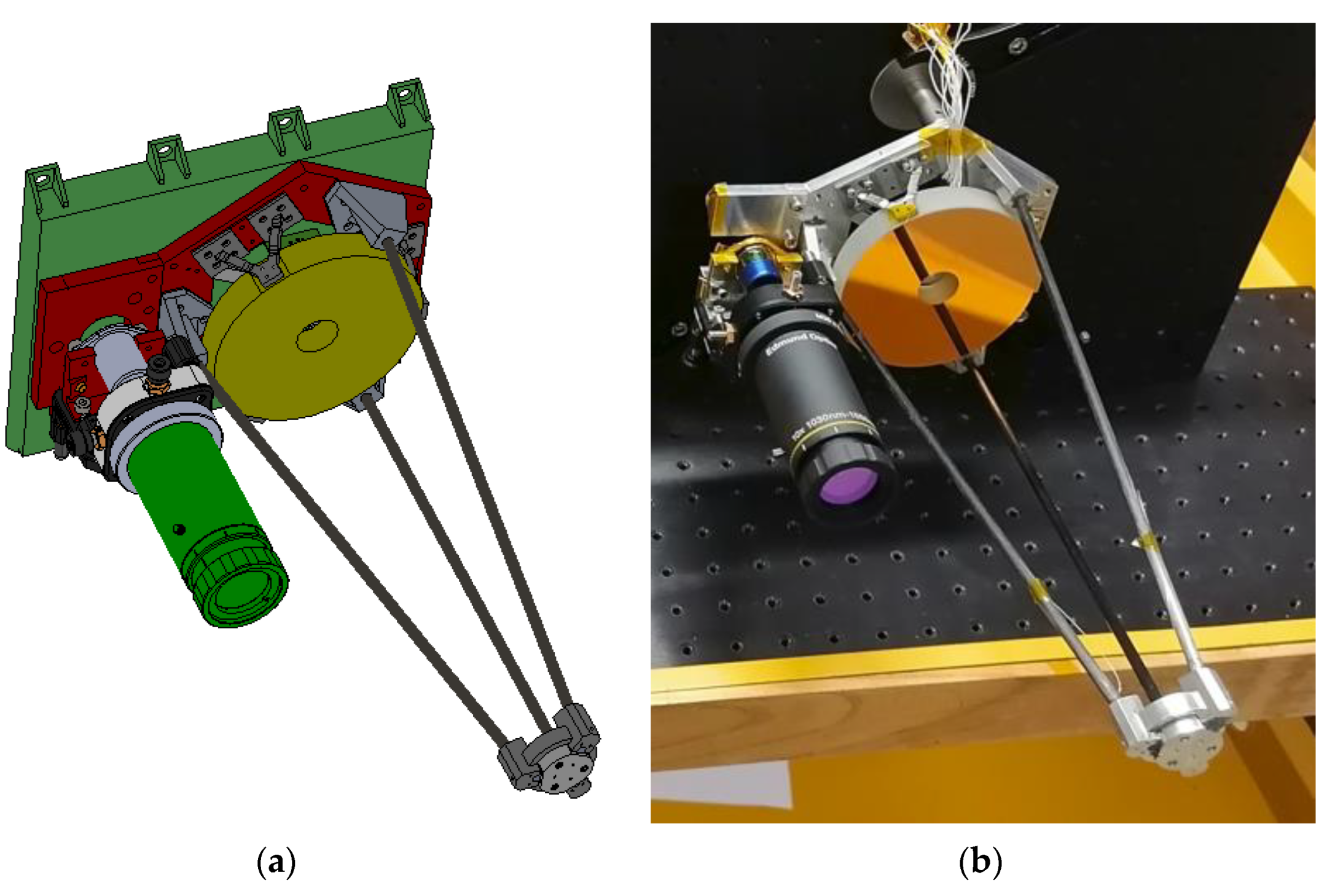
The Planetary ALTimeter (PALT) mechanical design has been optimized on different aspects to meet the requirements established for the HERA mission. In [6,7,8], the HELENA LIDAR’s performance was evaluated regarding weaker requirement of shock, static simulation of 5G in two different directions, and thermal conductive simulations between −40 °C and +60 °C. The main objective was to study the secondary mirror deformation towards the base of the telescope, and maximum stresses. Two different materials (aluminum and titanium) were assessed for the upper part of the LIDAR telescope. The simulations revealed a higher factor of safety, and a minor displacement of the secondary mirror towards the base of the telescope for the titanium material. This modification was implemented on PALT.
In order to guarantee that the best optical performance is maintained, the primary mirror shall be a-thermalized, which is possible by the optimizing the isostatic bipod mounts (see Figure 1). Furthermore, the assembly and alignment procedures of the primary mirror should be as simple as possible to avoid damages on the mirror. This paper presents an optimization of the isostatic bipod mounts design, and details on the assembly procedure.
3. Design
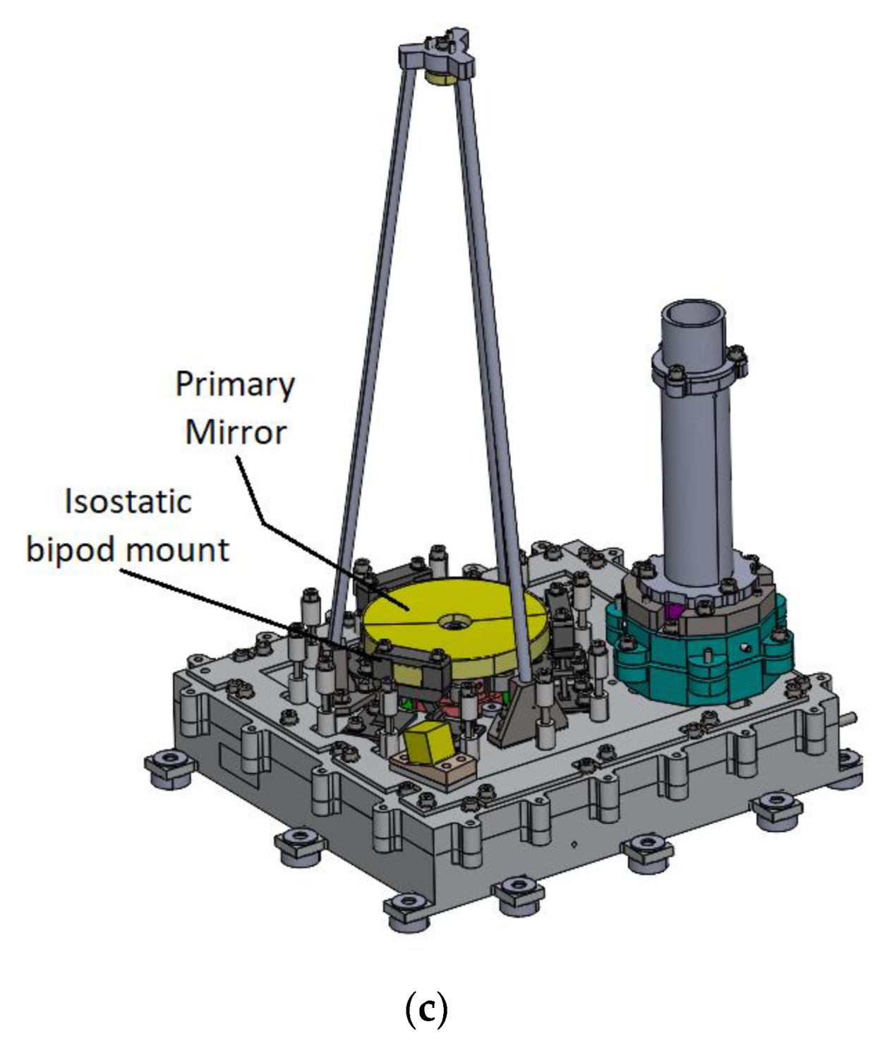
The design was iterated several times, with the focus being on the initial design and a final design. The first design of the isostatic bipod mounts was presented in HELENA [6,7], which was the starting point of the isostatic bipod mount for PALT. This first design is depicted in Figure 2.
The primary mirror of HELENA had a 100 mm diameter and 11 mm thickness.
For PALT, a 70 mm diameter mirror was required. A first approach on the isostatic bipods mount design was based on the HELENA’s optomechanics. The simulations of this design are presented in Section 4, and it was concluded that further optimization was desirable.
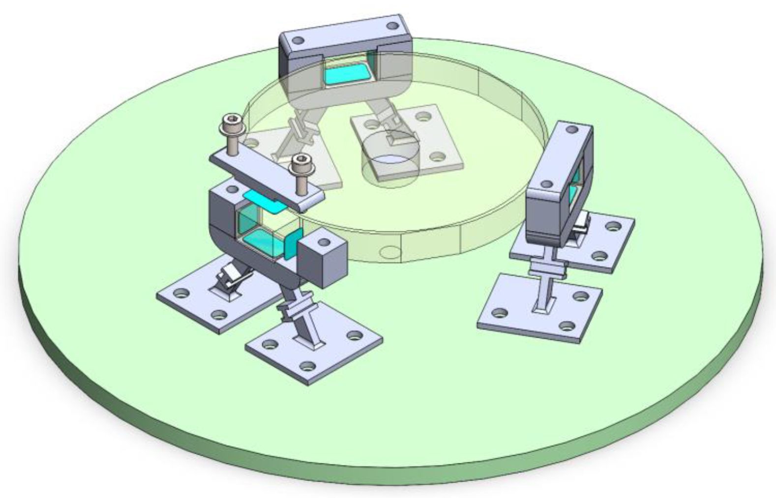
In a second version, the mirror’s thickness was decreased to 8 mm and the three extrude bosses were equally distributed with an 8 mm length (where isostatic bipod mounts are assembled). Both isostatic bipod mounts combine tangential and radial blades in each support leg, arranged in a triangle. The proposed design includes two blade radial flexures and a tangential blade between the radial blades, whose purpose is to compensate for radial and tangential deformations, respectively. The material chosen for this isostatic mount is Titanium Grade 5 (Ti-6Al-4V) (see Table 1).
The bipod isostatic mount presented in this article is shown in Figure 4, and it has dimensions of 33 mm height and a maximum length of 8 mm. Since the optimized implementation is a key element to achieve the required performance, the optimization of the design of the isostatic bipod mount was divided into four elements: a base flexure, two columns, and a top fitting. The separation of the bipod eases the bonding process between the mounts and the mirror extrude bosses.
The extruded areas presented in the inner upper structure of the isostatic bipod mount are adhesive areas where the mirror is to be attached. The adhesive is presented as a thin pad with 0.1 mm thickness.
4. Assembly and Bonding Procedures
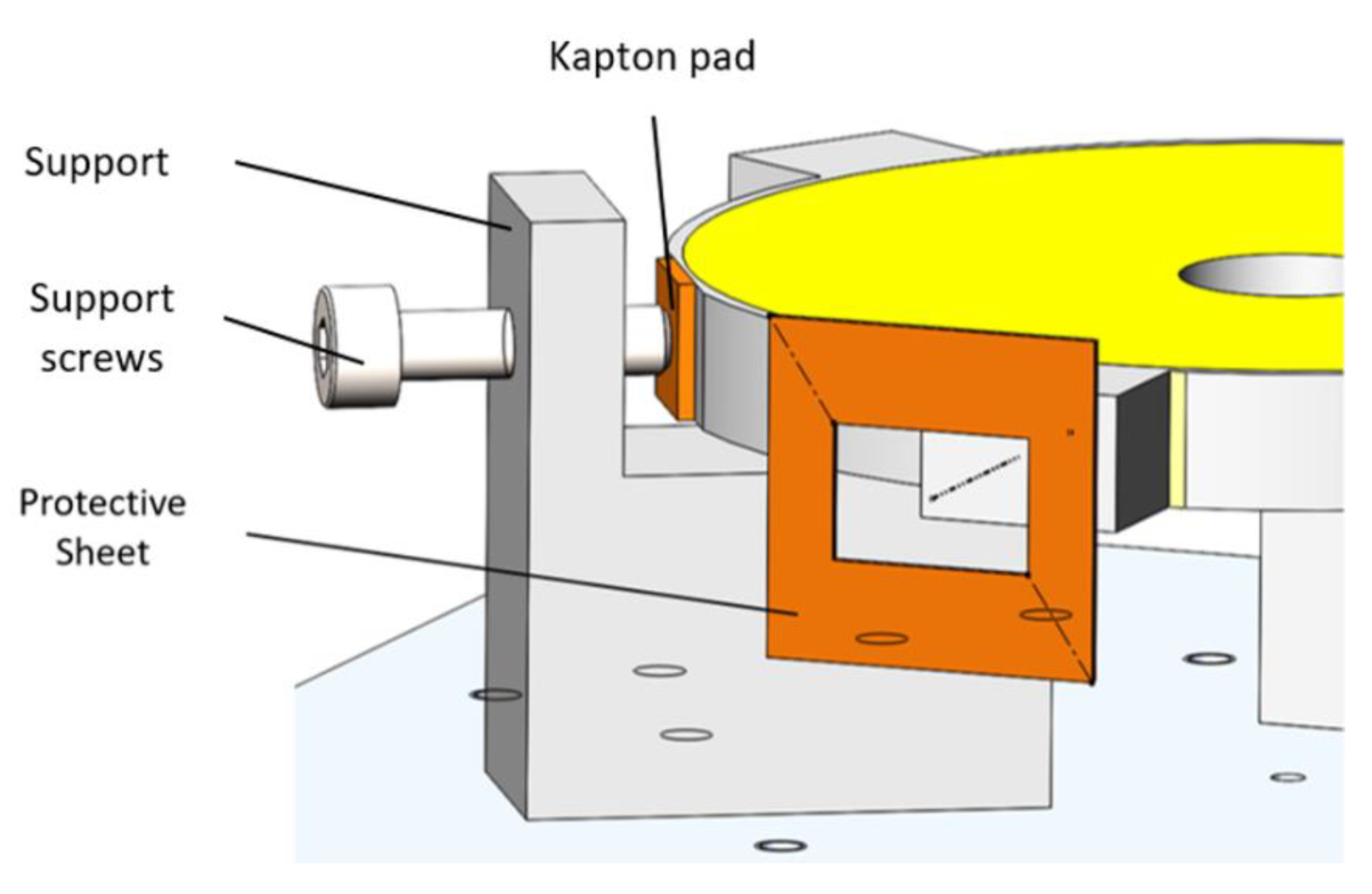
In HELENA, the isostatic bipod mount was bonded to the mirror with a 100 µm layer of adhesive. The bonding process was implemented by using a 100 µm diameter nylon wire, between the isostatic mount and the mirror, which were removed after the adhesive was fully cured. It was verified that the mount design blocked the application of the adhesive, which sprung the need for design changes. The isostatic bipod mount updated design is easily assembled and, since it is divided into four individual pieces, allow a better application of the epoxy without compromising the mirror. The bonding procedure is still to be qualified; however, the bonding procedure and the alignment procedure is defined. The first step fixates the mirror in space using three supports, assisted by Kapton pads and adjustment screws. A sheet made of Kapton, is to be placed on the mirror extrusions to ensure the adhesive is kept on the designated area and not touching the mirror optics surface (see Figure 5).
The adhesive thickness remains 100 µm apart from the flexures, on all four sides. To accomplish this, Kapton tape of a specific thickness is to be placed on the corners of the mirror extrusions. The tape serves, not only to guarantee that all four sides of the mirror extrusion will remain 100 µm apart from the flexures, but also to prevent any excess adhesive that may spread from the beyond the designated area (highlighted surfaces depicted in Figure 4). All the protective bonding components will be removed before the end of the work life of the adhesive.
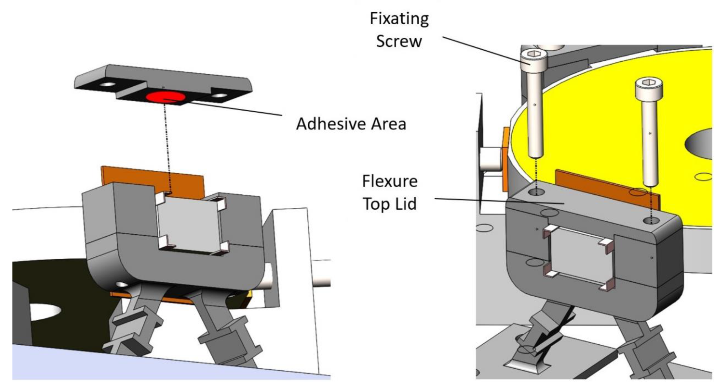
After assuring that the mirror is not contaminated by adhesive, the flexure base is placed under the mirror extrusion, with the adhesive already applied. The columns of the flexure are placed on the flexure base, both with the adhesive already applied, finalizing with the top lid of the flexure, with the adhesive already applied, and screwed into place, fixating the upper part of the flexure (see Figure 6). The two screws guarantee the connection of the isostatic bipod mount: the screw is inserted on the top fitting, goes through the columns, and reaches the flexure base.
5. Thermoelastic Simulations
This section presents the thermoelastic simulations of both designs and the respective results.
5.1. Thermal Modeling and Materials
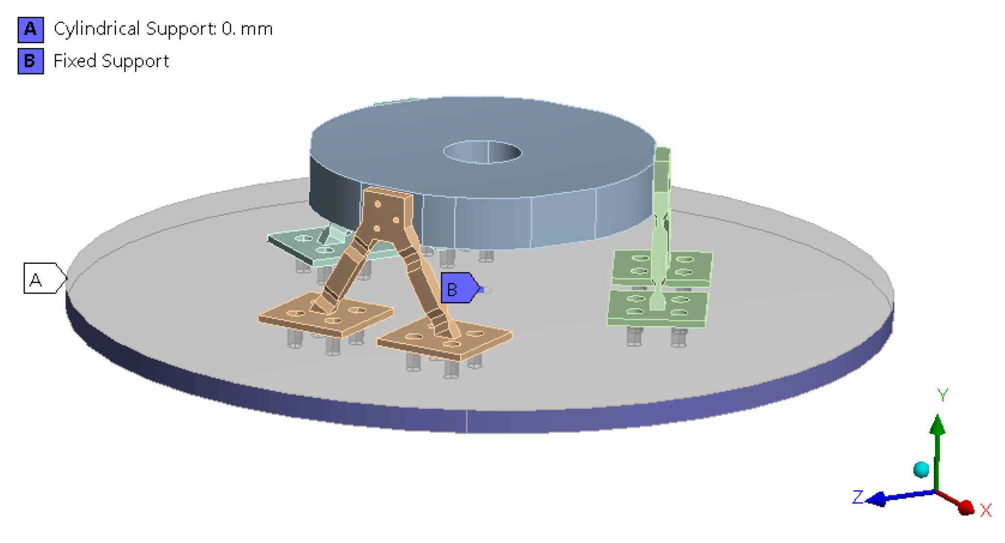
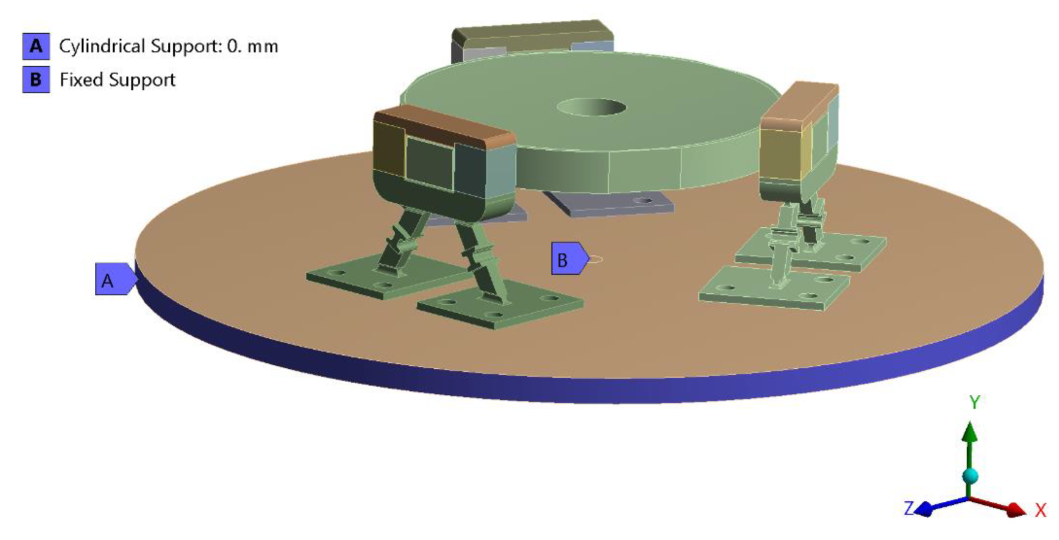
The isostatic bipod mounts were simulated in simple conditions to assess their behavior. The simulation only contemplated a circular base, to maintain the system symmetric, the three isostatic bipod mounts, and the mirror. In Figure 7, the simulation performed for the first design is depicted, and in Figure 8, the simulation performed for the optimized flexure design. The boundary conditions applied to the model were to prevent axial and tangential displacement, which means the base only has freedom radially, and a fixed-point support on the base center, which is coincident with the optical axis. The temperature was defined in the bottom surface of the base.
Both designs were subjected to the qualification non-operational temperature limits, i.e., +80 °C and −60 °C. The materials chosen were also the same: titanium grade 5 (Ti-6Al-4V) for the isostatic bipod mounts, aluminum 7075-T7351 for the base, Zerodur for the mirror, and Epoxy 2216B/A Gray for the adhesive pads. The properties of the chosen materials are presented in Table 1. The mechanical screw behavior was not assessed at this stage.
The Poisson’s ratio and the Young’s Modulus were given by the supplier and are confidential. The remaining properties are based on documentation [9,10]. The properties presented in Table 1 are the inputs needed for the thermo-elastic simulation.
The tolerance of the system is given by an optical study (i.e., tolerance analysis in ZEMAX). Regarding the telescope, it was identified that the worst tolerance offenders are the mirror radius and the mirror displacement. The tolerances that are assessed in this paper is the displacement on XZ plane of the primary mirror, the distance of the primary mirror to the base, and the curvature radius of the primary mirror (see Table 2).
5.2. Thermoelastic Results
The aim of these simulations was to assess the isostatic bipod mount’s behavior in the extreme temperatures. Two topics were studied, namely the survivability of the mirror (i.e., assessment of the stress in the mirror) and the analysis of the mirror displacement regarding its nominal position (to evaluate if the flexures were optimized and working correctly).
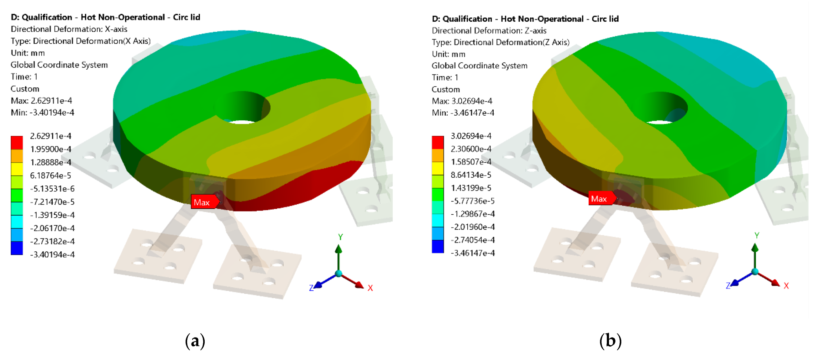
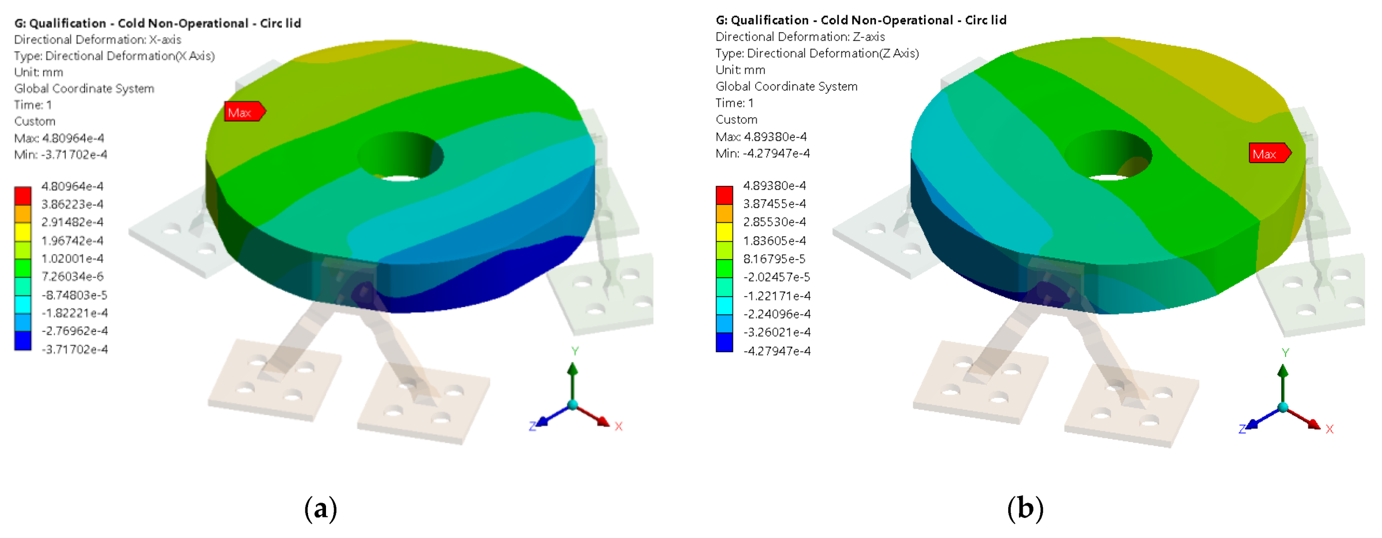
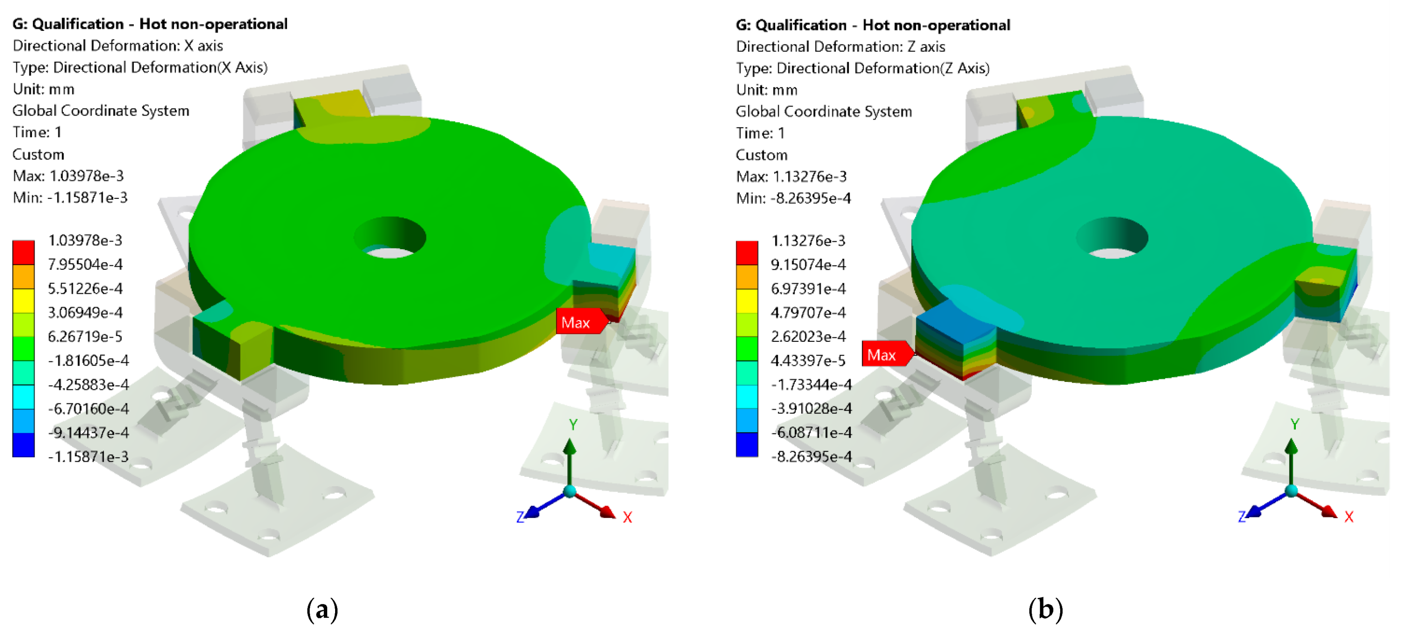
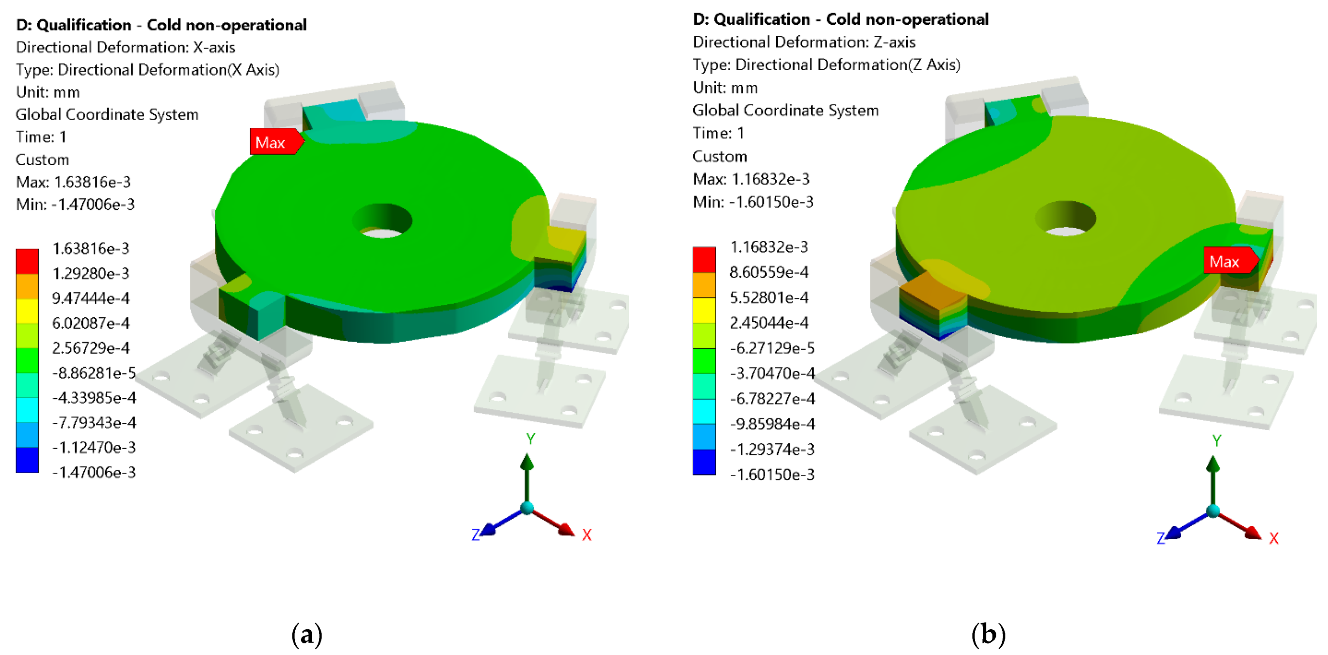
Figure 9 and Figure 10 represent the XZ displacement results for the first isostatic bipod mount design for the hot and cold non-operational scenarios, respectively.
From the results, it is evident that there is a displacement of the mirror relative to its nominal position. From the hot scenario, the extreme values of XZ displacement are in range of , and for the cold scenario, the extreme values of XZ displacement are in range of , which is fully within the range of acceptable tolerances from Table 2. An animation of the simulations can be found in (https://www.youtube.com/watch?v=M6bY21nINoE accessed on 23 March 2020)
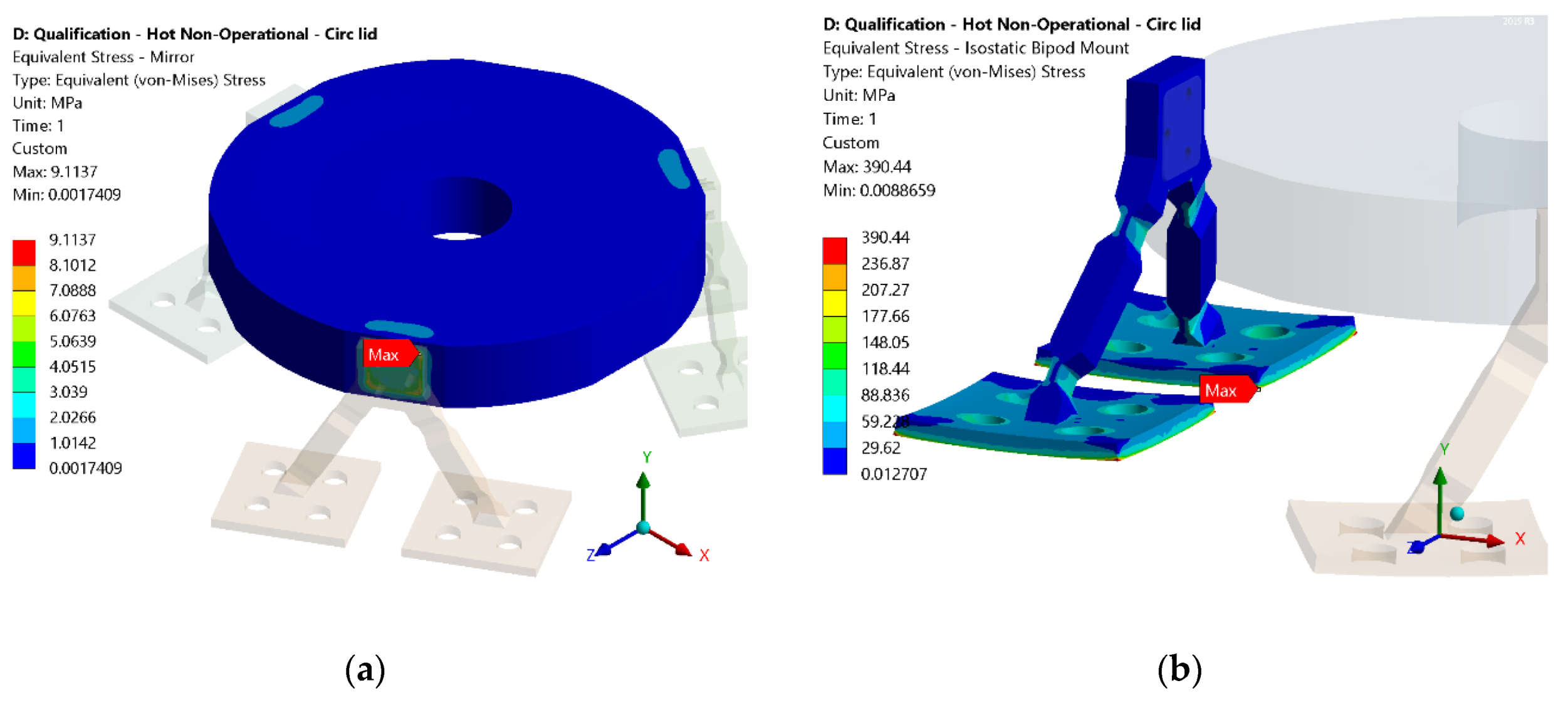
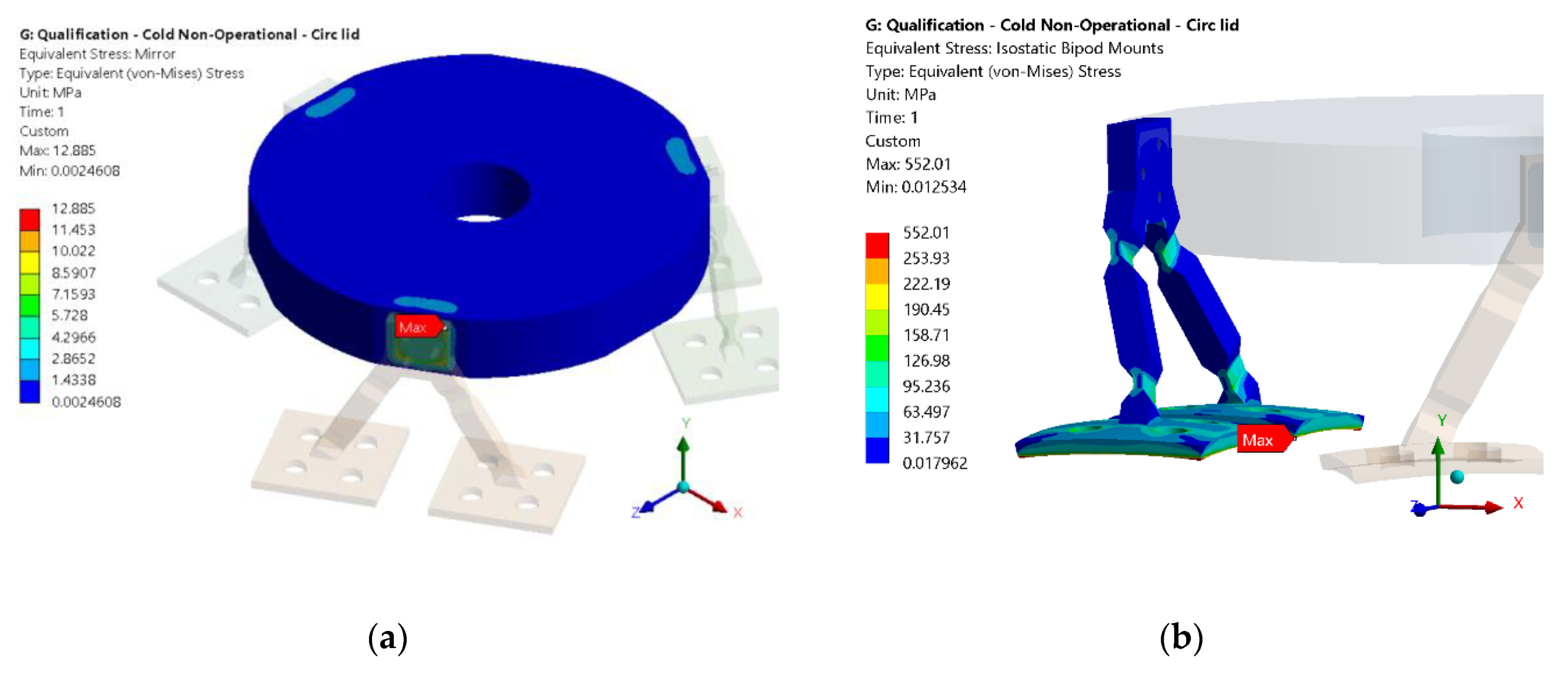
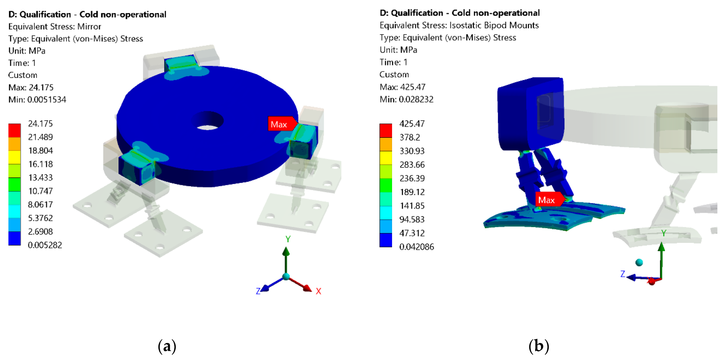
Regarding the stress, the critical components were analyzed, namely the mirror and the isostatic bipod mounts. The thermal conductance along the mirror and the adhesives, and between the adhesives and the isostatic bipod mounts is established as 2500 W/(m2K). The contacts between the other materials (aluminum and titanium) are established as 150 W/(m2K) (as defined in [11]). The results of the von-Mises stress for the hot non-operational case and for the cold non-operational case are presented in Figure 11 and Figure 12, respectively.
The mirror maximum stress is sited on the bonding areas, with a safety factor of 3.29 for the hot scenario, and 2.33 for the cold scenario, which means that the mirror will withstand the non-operational temperatures.
The isostatic bipod mounts have a good overall performance, since their displacement is located on the radial blades. The tangential blade does not present a considerable stress since the displacement condition is essentially radial. The maximum stress is located on the base of the isostatic bipod mounts, but since the critical stress is on the blades and in the bonding area, that maximum is not considered. When the maximum stress range is decreased, the value of stress starts to appear on the radial blade, which is coincident with the radial deformation of the base (see Figure 11b and Figure 12b). The safety factor for the isostatic bipod mount considers the maximum stress value, which converts into a safety factor of 2.82 for the hot scenario, and 1.99 for the cold scenario.
Making a similar study for the final design of the isostatic bipod mounts, the XZ displacement results are depicted in Figure 13 and Figure 14 for the hot and cold non-operational scenarios, respectively.
From the results, it is evident that there is a displacement of the mirror relative to its nominal position. Nevertheless, the results are within the established values for XZ displacement tolerances from Table 2. The extreme values of the hot non-operational temperatures for the final design of the isostatic bipod mounts are within the range of , and for the cold non-operational temperatures are in range of .
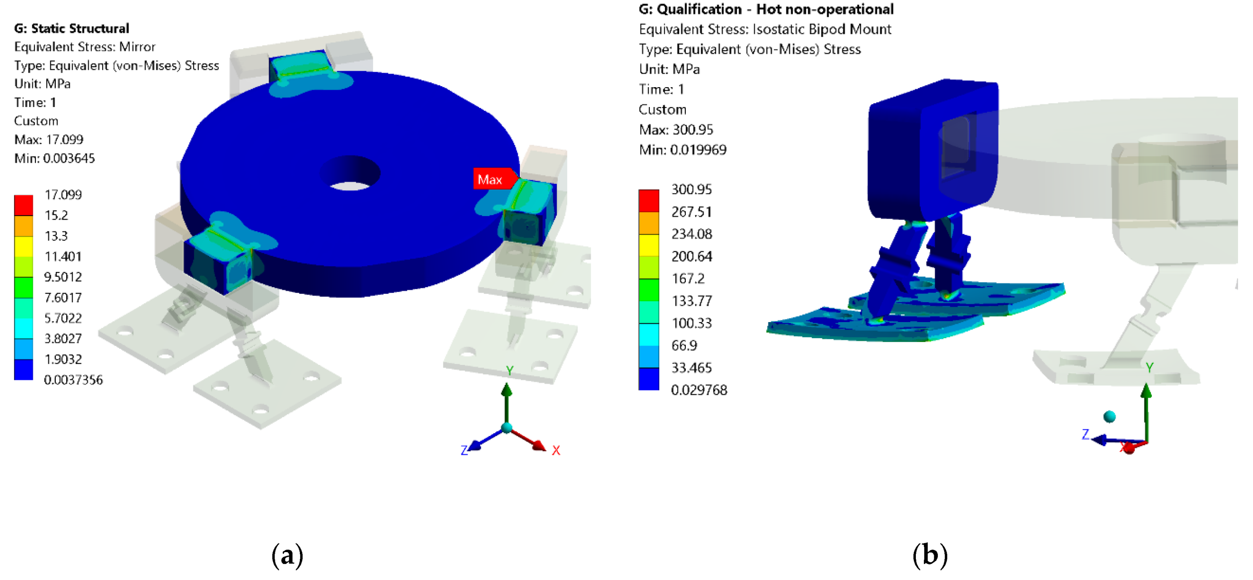
Regarding the stress in the mirror and the isostatic bipod mounts, the same assessment previously mentioned was made. The results are presented in Figure 15 and Figure 16 for the hot and cold non-operational scenario, respectively.
The mirror’s maximum stress is located on the bonding areas, with a safety factor of 1.75 for the hot scenario, and 1.24 for the cold scenario. Since the safety factor of the mirror is higher than unity, the mirror can withstand the hot and cold non-operational scenarios.
Regarding the isostatic bipod mounts stress distribution, it can be concluded that they have a good overall performance, since their displacement is located on the radial blades. The tangential blade does not present a considerable stress since the displacement condition is essentially radial.
The safety factor for the isostatic bipod mount converts into a safety factor of 3.66 for the hot scenario, and 2.59 for the cold scenario. Since the safety factor is higher than unity, the isostatic bipod mounts can withstand the hot and cold non-operational scenarios.
The maximum stress is found on the designated area of the radial blades (see Figure 15b and Figure 16b), which is expected.
The distance of the mirror towards the base for the first design is between , and for the final design is between . These values are within the requirement of defined in Table 2.
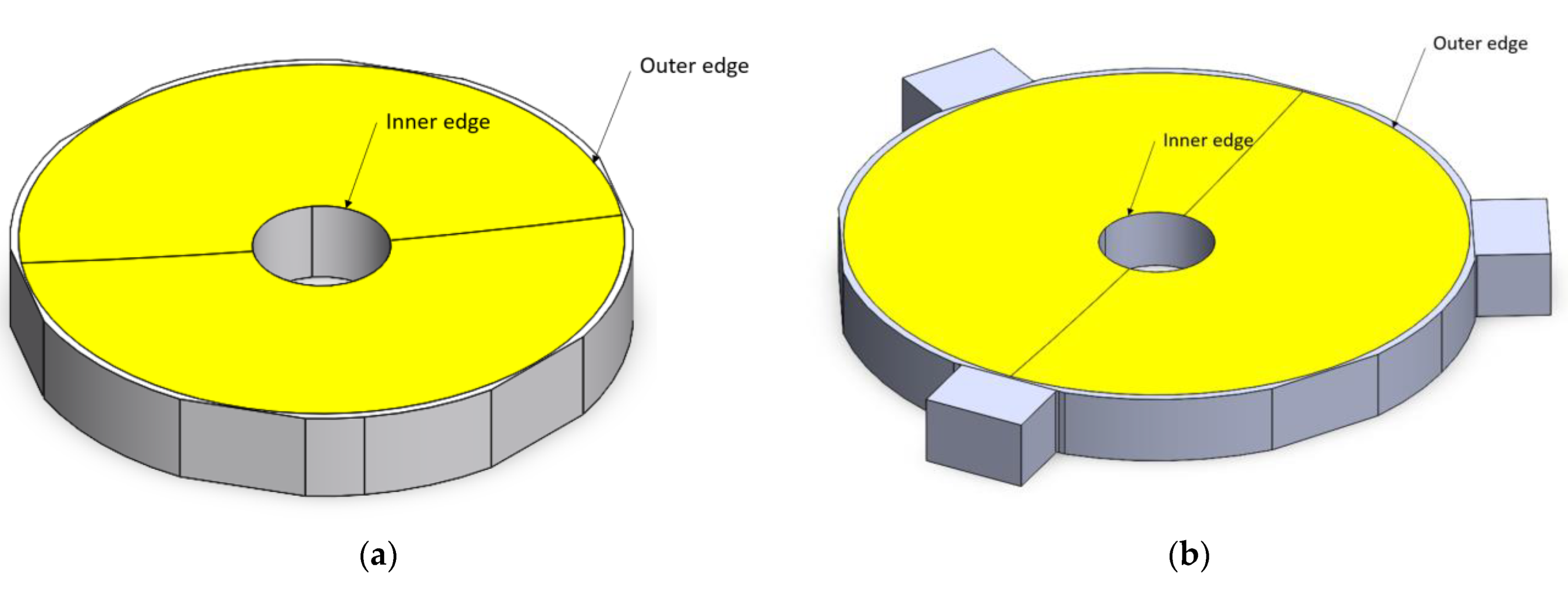
For the analysis of curvature radius variation, the following result processing approach was implemented: (1) the displacement offset of the mirror was removed; (2) the difference between the mirror outer edge and mirror inner edge was calculated (see Figure 19). To this difference we named the radius curvature variation of the mirror, and its results are presented in Table 3.
According to Table 2, a 1 mm curvature radius corresponds to a surface displacement of µm. The cold scenario does not fulfil this requirement; and for this case, the LIDAR performance has a loss of energy.
6. Conclusions
The paper describes the development of an isostatic bipod mount design for small mirrors that withstand severe temperature requirements. The assessment of the design was presented considering a preliminary design, which was already built but not yet tested, and the updated design, which is going to be built and subjected to testing.
The first design presents several complicated processes for bonding and alignment, which prompt a design that would be easier to integrate. Both designs present a viable design for the LIDAR, having taken into account the XZ displacement, the distance of the mirror towards the base, the curvature radius, and the stress on the mirror. Both designs survive the non-operational scenarios; however, the final design provides an easier implementation and bonding procedure, since it is divided into four individual parts, in contrast to the first design. Additionally, it is expected that the final design has a higher resistance to shock, because the bonding of the mirror is implemented in four perpendicular areas per isostatic bipod mount instead of only one.
The future steps include the assessment of the performance of the isostatic bipod mounts assembled in the PALT, and consequently, the evaluation of the optical performance of PALT.
Author Contributions
Conceptualization, N.G.D., P.G., H.O., R.M. and A.A.; methodology, N.G.D., P.G., H.O., R.M. and A.A.; software, N.G.D.; investigation, N.G.D., P.G., H.O., R.M. and A.A.; writing—original draft preparation, N.G.D.; writing—review and editing, N.G.D., P.G., H.O., R.M. and A.A.; validation, N.G.D., P.G., H.O., R.M. and A.A.; supervision, N.G.D., P.G., H.O., R.M. and A.A. All authors have read and agreed to the published version of the manuscript.
Funding
This research received no external funding.
Institutional Review Board Statement
Not applicable.
Informed Consent Statement
Not applicable.
Data Availability Statement
Not applicable.
Acknowledgments
European Union’s Horizon 2020 research and innovation programme under Grant Agreement No. 870377 (Project No. NEO-MAPP). FCT (Foundation for Science and Technology, I.P.), through: CENTRA, project UIDB/00099/2020; LAETA project UIDB/50022/2020; ICT project UIDP/04683/2020.
Conflicts of Interest
The authors declare no conflict of interest.
Nomenclature
| CTE | Coefficient of Thermal Expansion |
| LIDAR | Light Detection and Ranging |
| PALT | Planetary ALTimeter |
| ToF | Time of Flight |
References
- Yoder, P.R., Jr. Opto-Mechanical Systems Design; CRC Press: Boca Raton, FL, USA, 2015. [Google Scholar]
- Pijnenburg, J.A.; te Voert, M.J.; de Vreugd, J.; Vosteen, A.; van Werkhoven, W.; Mekking, J.; Nijland, B.A. Ultra-stable isostatic bonded optical mount design for harsh environments. In Modern Technologies in Space-And Ground-Based Telescopes and Instrumentation II; International Society for Optics and Photonics: Bellingham, DC, USA, 2012; Volume 8450, p. 845027. [Google Scholar]
- Kihm, H.; Yang, H.S.; Moon, I.K.; Yeon, J.H.; Lee, S.H.; Lee, Y.W. Adjustable bipod flexures for mounting mirrors in a space telescope. Appl. Opt. 2012, 51, 7776–7783. [Google Scholar]
- Kihm, H.; Yang, H.S.; Lee, Y.W. Bipod flexure for 1-m primary mirror system. Rev. Sci. Instrum. 2014, 85, 125101. [Google Scholar]
- Liu, B.; Wang, W.; Qu, Y.J.; Li, X.P.; Wang, X.; Zhao, H. Design of an adjustable bipod flexure for a large-aperture mirror of a space camera. Appl. Opt. 2018, 57, 4048–4055. [Google Scholar]
- Dias, N.G.; Arribas, B.N.; Gordo, P.; Sousa, T.; Marinho, J.; Melicio, R.; Amorim, A.; Michel, P. LIDAR altimeter conception for HERA spacecraft. Aircr. Eng. Aerosp. Technol. 2021, 93, 1018–1028. [Google Scholar]
- Dias, N.G.; Arribas, B.N.; Gordo, P.; Sousa, T.; Marinho, J.; Melicio, R.; Amorim, A.; Michel, P. HERA mission LIDAR altimeter implementation. In IOP Conference Series: Materials Science and Engineering; IOP Publishing: Bristol, UK, 2021; Volume 1024, p. 012112. [Google Scholar]
- Dias, N.G.; Arribas, B.N.; Gordo, P.; Sousa, T.; Marinho, J.; Melicio, R.; Amorim, A.; Livio, B.; Michel, P. HERA mission LIDAR mechanical and optical design. In IOP Conference Series: Materials Science and Engineering; IOP Publishing: Bristol, UK, 2022; Volume 1026, p. 012094. [Google Scholar]
- Côté, P.; Desnoyers, N. Thermal stress failure criteria for a structural epoxy. Optomech. Innov. Solut. 2011, 8125, 81250K. [Google Scholar]
- 3M Science, 3M™ Scotch-Weld™ Epoxy Adhesive 2216 B/A Gray. Available online: https://www.generaladhesivos.com/proveedor-pegamento/62hoja-tecnica-3M%20Scotch-Weld%20Epoxy%20Adhesive%202216%20B_A%20Gray%20(1).pdf (accessed on 1 December 2021).
- Yovanovich, M.M. Thermal Interface (Joint) Conductance and Resistance, ECE 309 Course Notes. Available online: http://www.mhtl.uwaterloo.ca/courses_old/ece309/notes/conduction/cont.pdf (accessed on 1 December 2021).
Figure 1.
(a) HELENA design; (b) HELENA engineering model. (c) PALT design. Several transformations were made since HELENA design, with the isostatic bipod mounts being a critical design improvement.
Figure 1.
(a) HELENA design; (b) HELENA engineering model. (c) PALT design. Several transformations were made since HELENA design, with the isostatic bipod mounts being a critical design improvement.


Figure 2.
First design of isostatic bipod mount, which are positioned symmetrically around the mirror, and the representation of the adhesive pads area (highlighted in green).
Figure 2.
First design of isostatic bipod mount, which are positioned symmetrically around the mirror, and the representation of the adhesive pads area (highlighted in green).

Figure 3.
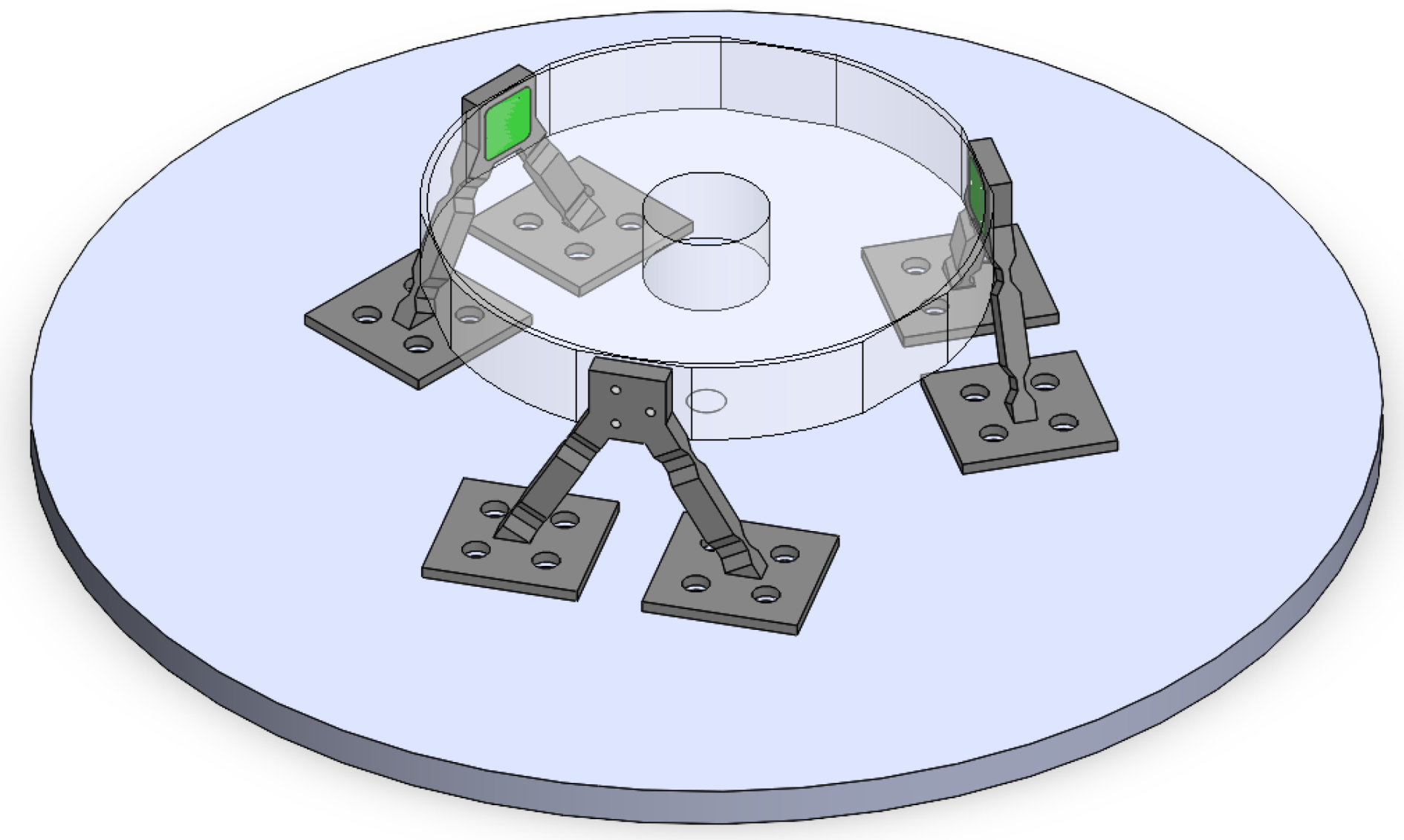
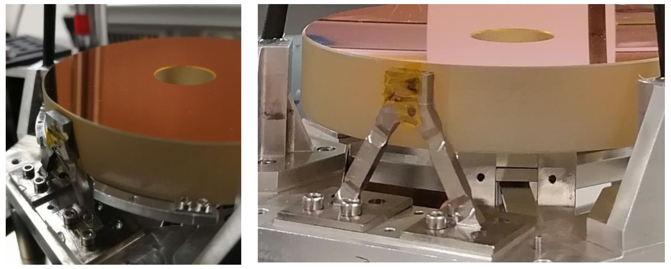
Isostatic bipod mount assembled on HELENA.

Figure 4.
Isostatic bipod mount that will be assembled in PALT. They are positioned symmetrically around the mirror, and the adhesive pads area are displayed (highlighted in blue).
Figure 4.
Isostatic bipod mount that will be assembled in PALT. They are positioned symmetrically around the mirror, and the adhesive pads area are displayed (highlighted in blue).

Figure 5.
Mirror fixation and protection. The protective sheet is perforated to allow an easy removal after assembly and bonding of the flexures.
Figure 5.
Mirror fixation and protection. The protective sheet is perforated to allow an easy removal after assembly and bonding of the flexures.

Figure 6.
Final step on the bonding procedure. The protective sheets are removed before the end of the work life of the adhesive (schematic).
Figure 6.
Final step on the bonding procedure. The protective sheets are removed before the end of the work life of the adhesive (schematic).

Figure 7.
The boundary conditions of the first design.

Figure 8.
The boundary conditions of the final design.

Figure 9.
Result of hot (+80 °C) non-operational scenario—First design: (a) X-axis displacement, (b) Z-axis displacement.
Figure 9.
Result of hot (+80 °C) non-operational scenario—First design: (a) X-axis displacement, (b) Z-axis displacement.

Figure 10.
Result of cold (−60 °C) non-operational scenario—First design: (a) X-axis displacement, (b) Z-axis displacement.
Figure 10.
Result of cold (−60 °C) non-operational scenario—First design: (a) X-axis displacement, (b) Z-axis displacement.

Figure 11.
Result of hot (+80 °C) non-operational scenario—First design: (a) Mirror stress, (b) Isostatic bipod mount stress (deformation scale factor: 76).
Figure 11.
Result of hot (+80 °C) non-operational scenario—First design: (a) Mirror stress, (b) Isostatic bipod mount stress (deformation scale factor: 76).

Figure 12.
Result of cold (−60 °C) non-operational scenario—First design: (a) Mirror stress, (b) Isostatic bipod mount stress (deformation scale factor: 76).
Figure 12.
Result of cold (−60 °C) non-operational scenario—First design: (a) Mirror stress, (b) Isostatic bipod mount stress (deformation scale factor: 76).

Figure 13.
Result of hot (+80 °C) non-operational scenario—Final design: (a) X-axis displacement, (b) Z-axis displacement.
Figure 13.
Result of hot (+80 °C) non-operational scenario—Final design: (a) X-axis displacement, (b) Z-axis displacement.

Figure 14.
Result of cold (−60 °C) non-operational scenario—Final design: (a) X-axis displacement, (b) Z-axis displacement.
Figure 14.
Result of cold (−60 °C) non-operational scenario—Final design: (a) X-axis displacement, (b) Z-axis displacement.

Figure 15.
Result of hot (+80 °C) non-operational scenario—Final design: (a) Mirror stress, (b) Isostatic bipod mount stress (deformation scale factor: 73).
Figure 15.
Result of hot (+80 °C) non-operational scenario—Final design: (a) Mirror stress, (b) Isostatic bipod mount stress (deformation scale factor: 73).

Figure 16.
Result of cold (−60 °C) non-operational scenario—Final design: (a) Mirror stress, (b) Isostatic bipod mount stress (deformation scale factor: 73).
Figure 16.
Result of cold (−60 °C) non-operational scenario—Final design: (a) Mirror stress, (b) Isostatic bipod mount stress (deformation scale factor: 73).

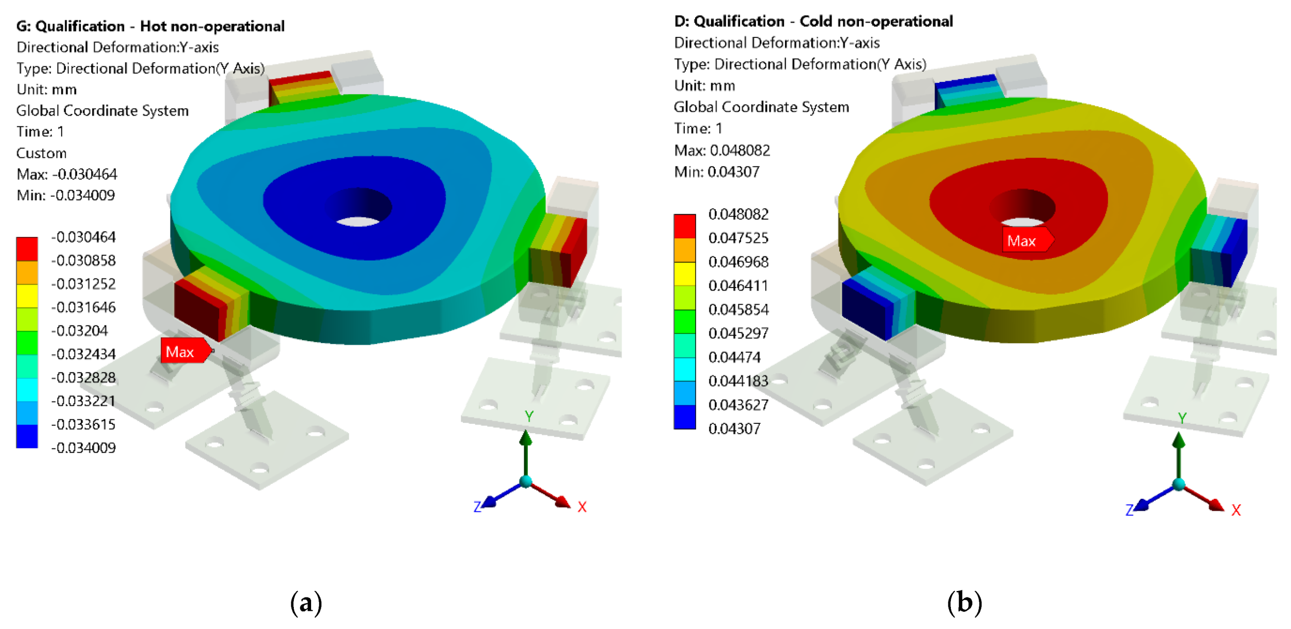
Figure 17.
Result of Y-axis displacement for the first design: (a) hot (+80 °C) non-operational scenario, (b) cold (−60 °C) non-operational scenario.
Figure 17.
Result of Y-axis displacement for the first design: (a) hot (+80 °C) non-operational scenario, (b) cold (−60 °C) non-operational scenario.

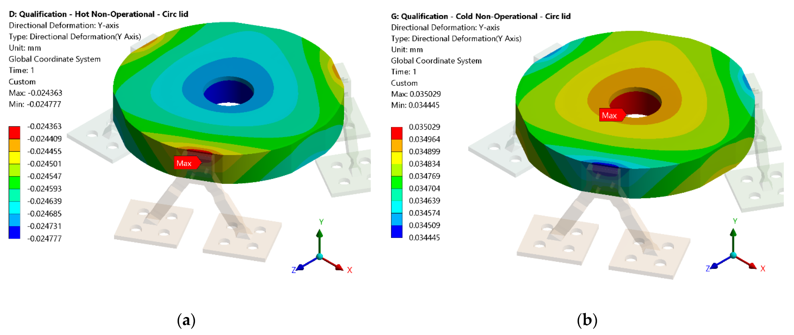
Figure 18.
Result of Y-axis displacement for the final design: (a) hot (+80 °C) non-operational scenario, (b) cold (−60 °C) non-operational scenario.
Figure 18.
Result of Y-axis displacement for the final design: (a) hot (+80 °C) non-operational scenario, (b) cold (−60 °C) non-operational scenario.

Figure 19.
Representation of the inner and outer edge of the mirror: (a) first design, (b) final design.
Figure 19.
Representation of the inner and outer edge of the mirror: (a) first design, (b) final design.


Table 1.
Properties of the materials.
| Material | Physical Property | Value |
|---|---|---|
| Zerodur | Density | 2530 kg/m3 |
| Coefficient of Thermal Expansion | 1 × 10⁻⁷/K | |
| Elastic modulus | 84.7 GPa | |
| Poisson’s ratio | 0.25 | |
| Thermal conductivity | 1.46 W/m.K | |
| Ultimate strength | 30 MPa | |
| Aluminium 7075-T7351 | Density | 2800 kg/m3 |
| Coefficient of Thermal Expansion | 2.36 × 10⁻⁵/K | |
| Elastic modulus | 72 GPa | |
| Poisson’s ratio | 0.33 | |
| Thermal conductivity | 155 W/m.K | |
| Yield strength | 435 MPa | |
| Titanium Grade 5 (Ti-6Al-4V) | Density | 4430 kg/m3 |
| Coefficient of Thermal Expansion | 8.6 × 10⁻⁶/K | |
| Elastic modulus | 113.8 GPa | |
| Poisson’s ratio | 0.33 | |
| Thermal conductivity | 6.7 W/m.K | |
| Yield strength | 1100 MPa | |
| Epoxy 2216B/A Gray | Density | 1300 kg/m3 |
| Coefficient of Thermal Expansion | 102 × 10−6/K | |
| Thermal conductivity | 0.394 W/m.K | |
| Ultimate strength | 10.2 MPa |
Table 2.
Thermal acceptable tolerances.
| Component | Value [mm] | Comments | |
|---|---|---|---|
| Primary Mirror | XZ displacement | ±0.01 | |
| Distance of Mirror to the Base | ±0.09 | ||
| Curvature radius | ±1 | ±1 mm radius variation is equivalent of a maximum surface displacement of ±2 µm |
Table 3.
Curvature radius deformation.
| First Design | Final Design | |||
|---|---|---|---|---|
| Hot Scenario | Cold Scenario | Hot Scenario | Cold Scenario | |
| Radius curvature variation [µm] | 0.287 | 0.406 | 1.85 | 2.62 |
Publisher’s Note: MDPI stays neutral with regard to jurisdictional claims in published maps and institutional affiliations. |
© 2022 by the authors. Licensee MDPI, Basel, Switzerland. This article is an open access article distributed under the terms and conditions of the Creative Commons Attribution (CC BY) license (https://creativecommons.org/licenses/by/4.0/).
Share and Cite
MDPI and ACS Style
Dias, N.G.; Gordo, P.; Onderwater, H.; Melicio, R.; Amorim, A. Analysis on the Isostatic Bipod Mounts for the HERA Mission LIDAR. Appl. Sci. 2022, 12, 3497. https://0-doi-org.brum.beds.ac.uk/10.3390/app12073497
AMA Style
Dias NG, Gordo P, Onderwater H, Melicio R, Amorim A. Analysis on the Isostatic Bipod Mounts for the HERA Mission LIDAR. Applied Sciences. 2022; 12(7):3497. https://0-doi-org.brum.beds.ac.uk/10.3390/app12073497
Chicago/Turabian StyleDias, Nicole G., Paulo Gordo, Hugo Onderwater, Rui Melicio, and António Amorim. 2022. "Analysis on the Isostatic Bipod Mounts for the HERA Mission LIDAR" Applied Sciences 12, no. 7: 3497. https://0-doi-org.brum.beds.ac.uk/10.3390/app12073497
Note that from the first issue of 2016, this journal uses article numbers instead of page numbers. See further details here.