
Experimental Investigation of Concrete Sandwich Walls with Glass-Fiber-Composite Connectors Exposed to Fire and Mechanical Loading

Abstract
:1. Introduction
- The potential use of a sandwich wall as a fire wall. The fire resistance of a sandwich wall and the fire behaviour of its components were tested and analysed, taking into account the REI-M [18] requirements for load-bearing fire walls.
- The structural integrity of a sandwich wall under fire and impact load. The mechanical coupling of a facing wythe, unsupported at the base, to a load-bearing wythe must not deteriorate to the extent that it falls off during fire exposure time or impact loading.
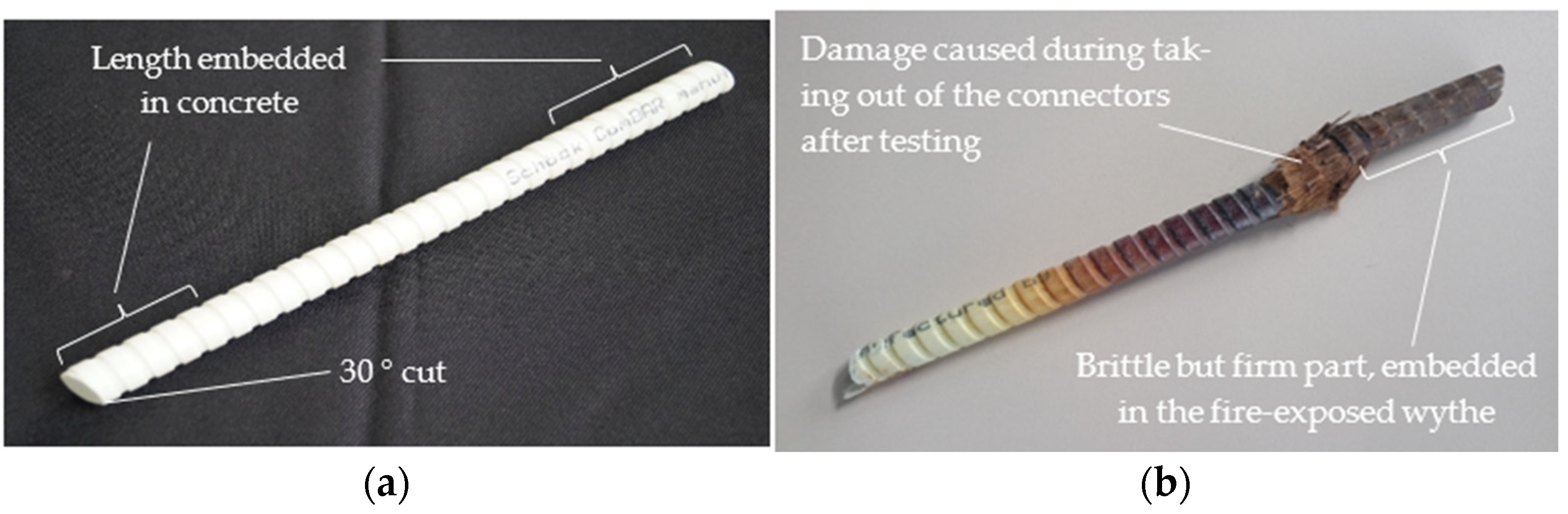
- The fire behaviour of GFRP connectors. The mechanical performance of connectors, e.g., their support for the facing concrete wythe and their contribution to the shear and flexural stiffness of the wall and anchorage safety in the presence of fire was investigated. Furthermore, their behaviour in terms of combustibility, fire spread and smoke evolution was analysed. Heat-damaged connectors can leave empty holes in wythes or enhance heat-induced concrete spalling, degrading the space-enclosing function of walls. The impact of these effects on the fire resistance of an entire wall was assessed.
- The composite action of a sandwich wall in the presence of fire. The degree of mechanical coupling of both concrete wythes over time in a fire situation should be analysed. The higher degree of composite action sustained through longer fire exposure times is a substantial contribution to the structural robustness of walls [19] and enhances their fire resistance.
2. Experimental Program
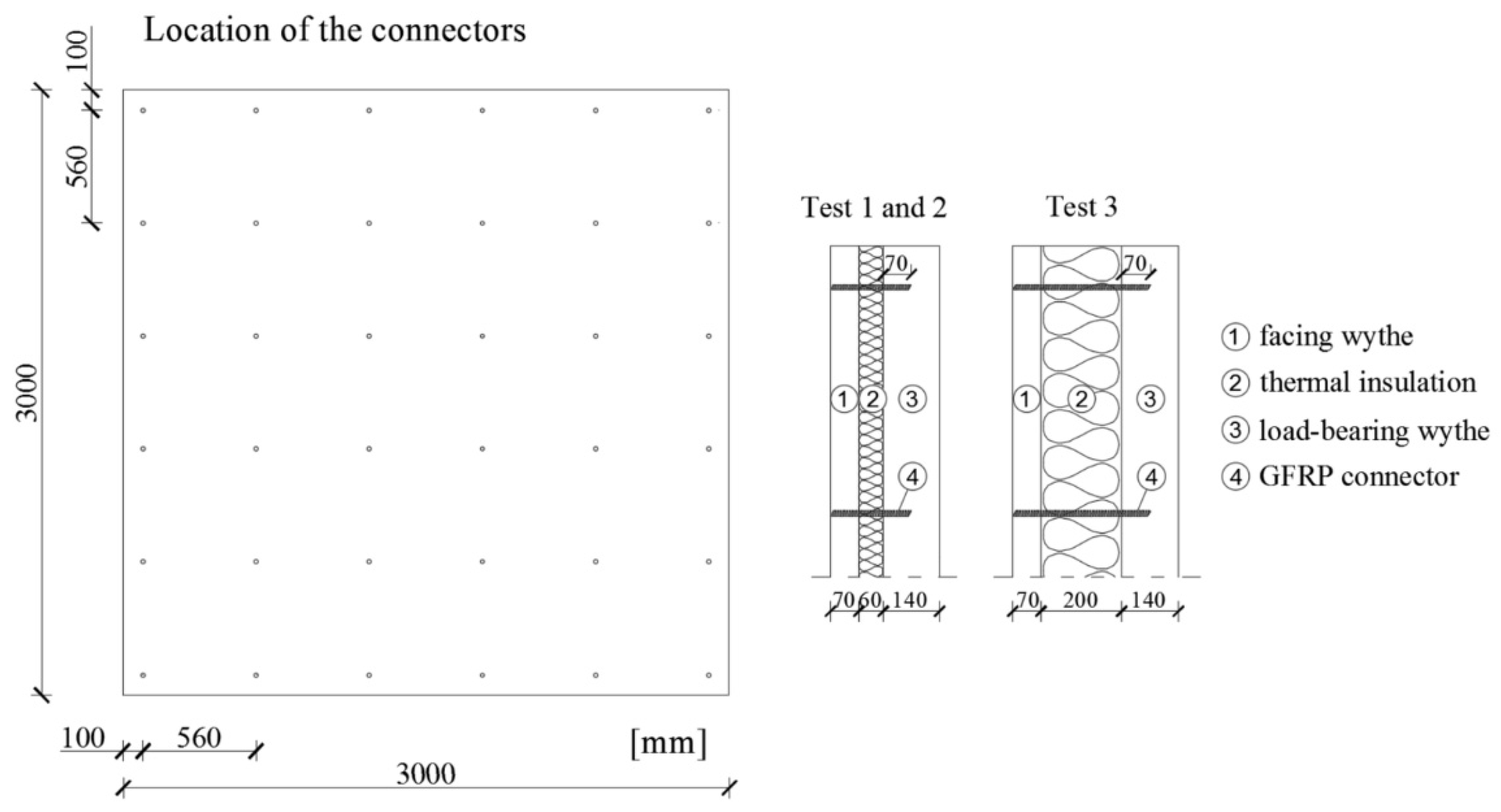
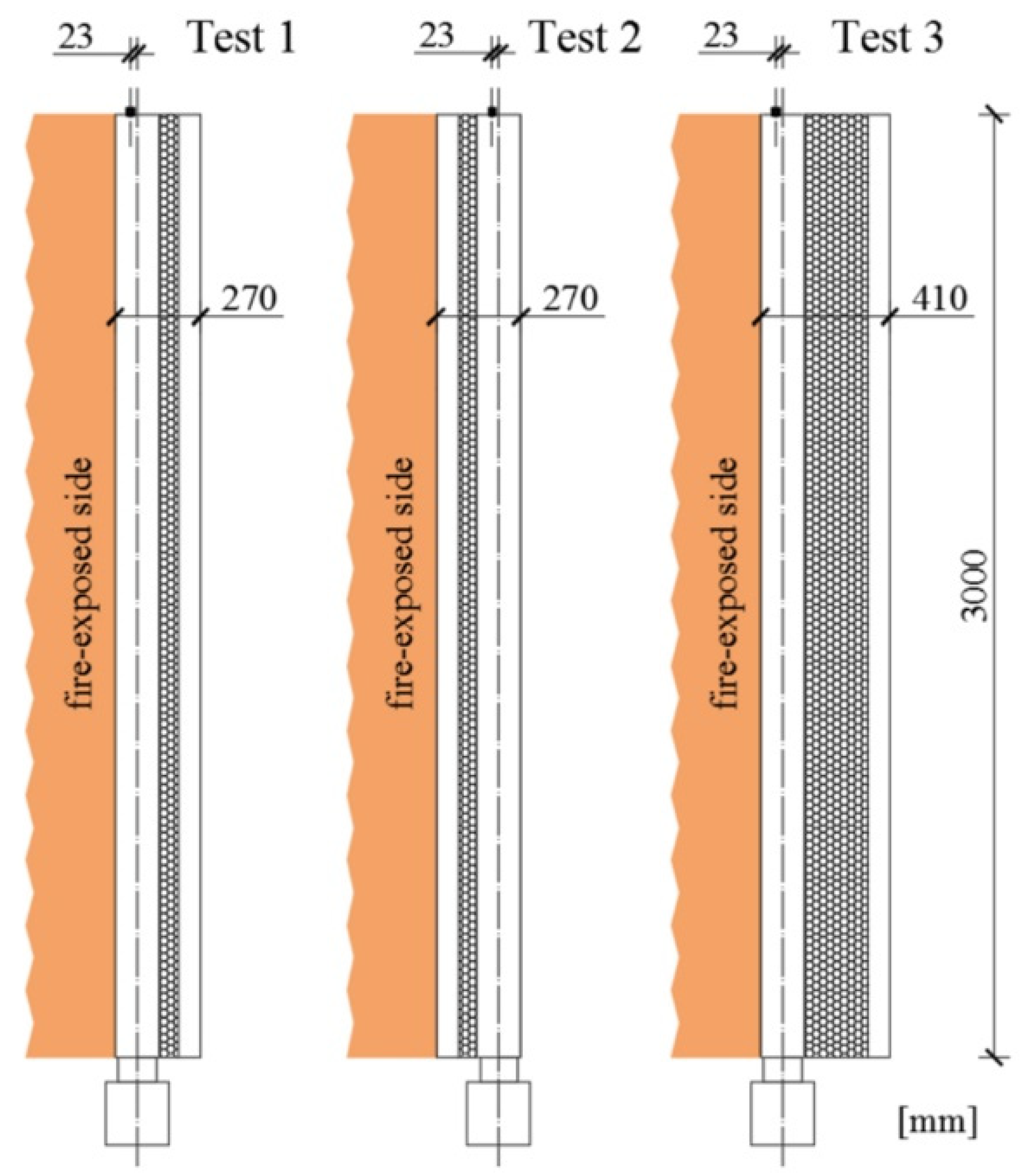
2.1. Specimens
2.2. Specimen Configuration
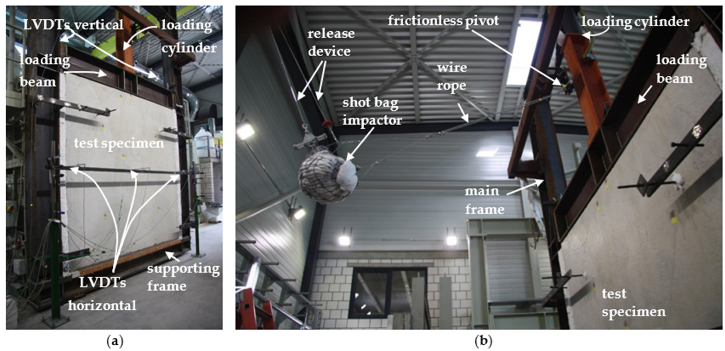
2.3. Test Setup and Procedure
2.4. Loading
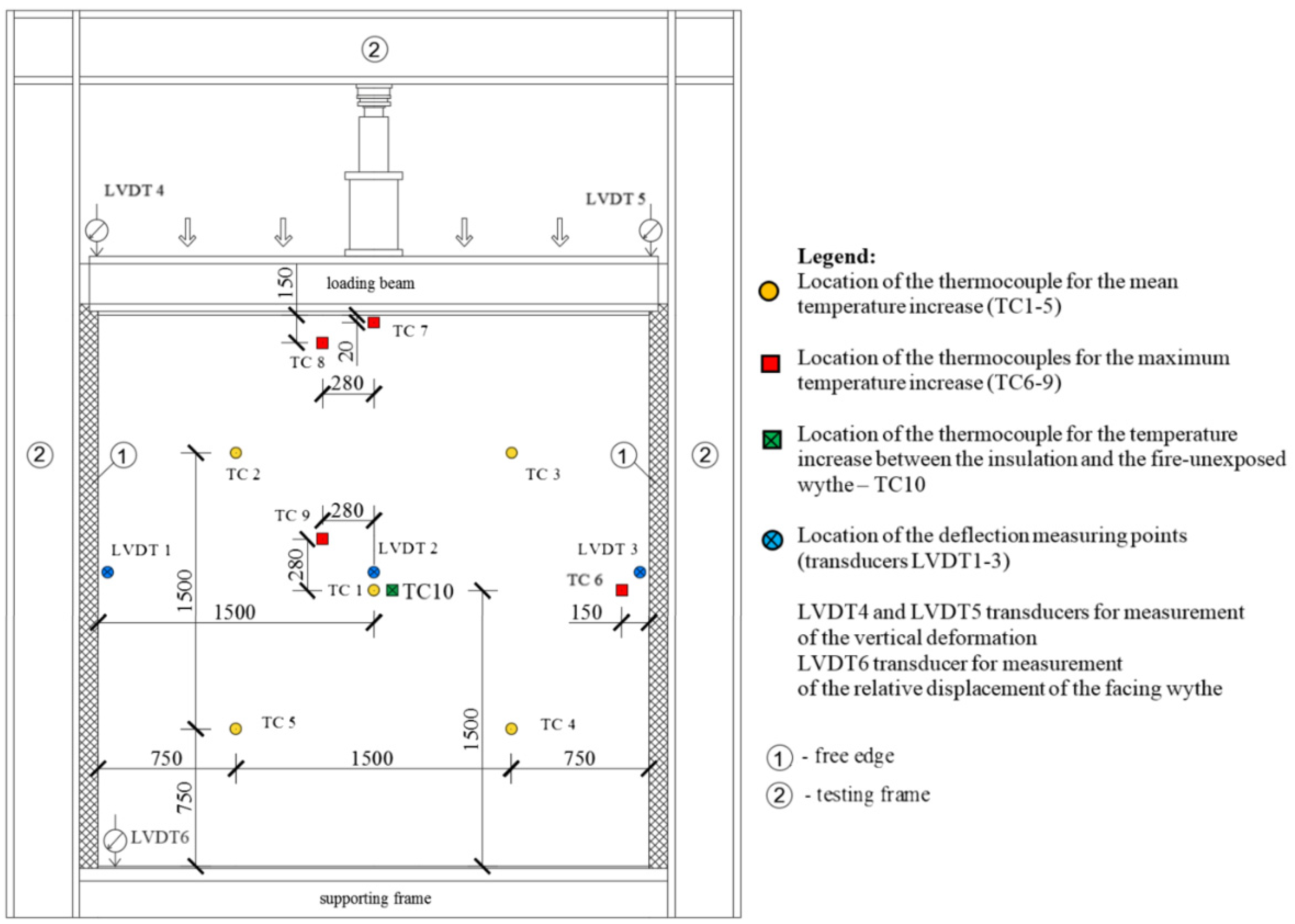
2.5. Measurement
3. Test Results and Discussion
3.1. Structural Behaviour
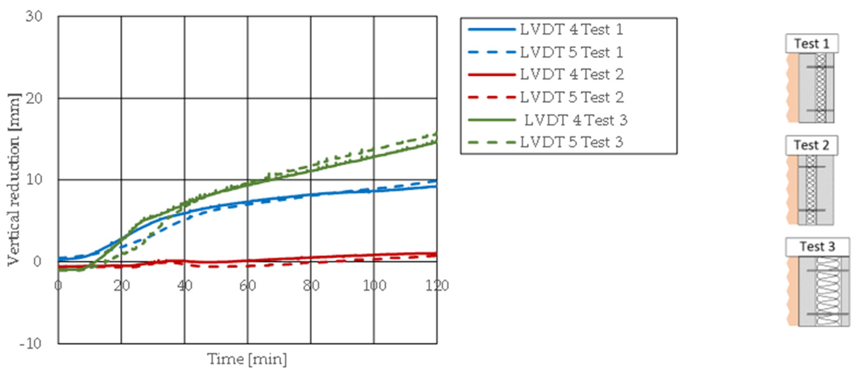
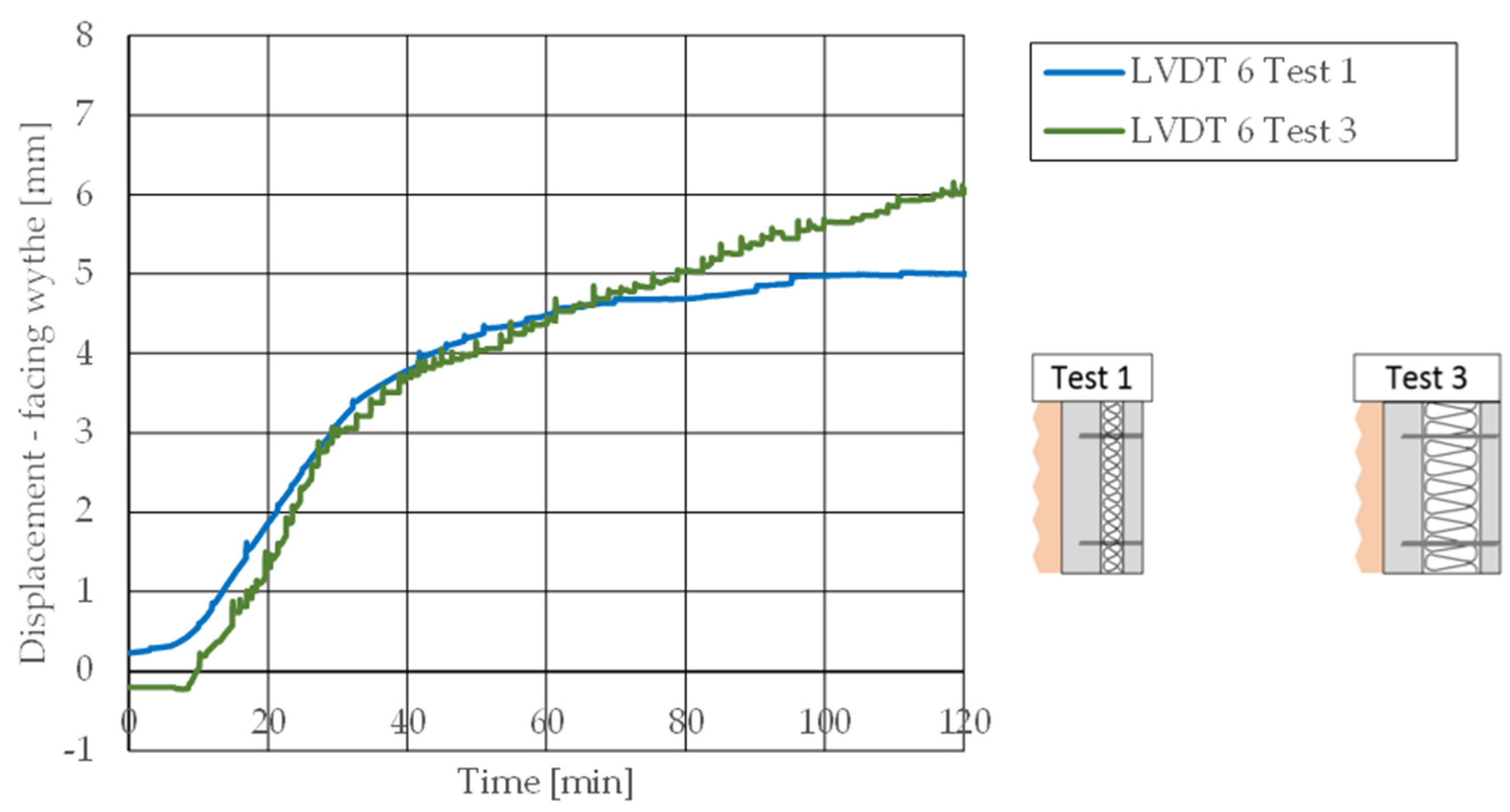
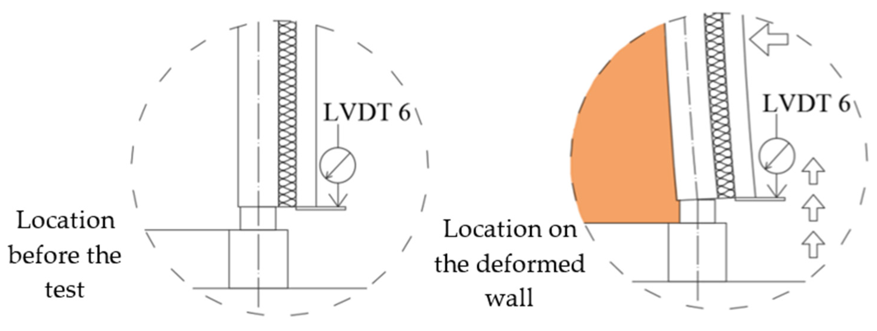
3.2. Axial Displacement Behaviour
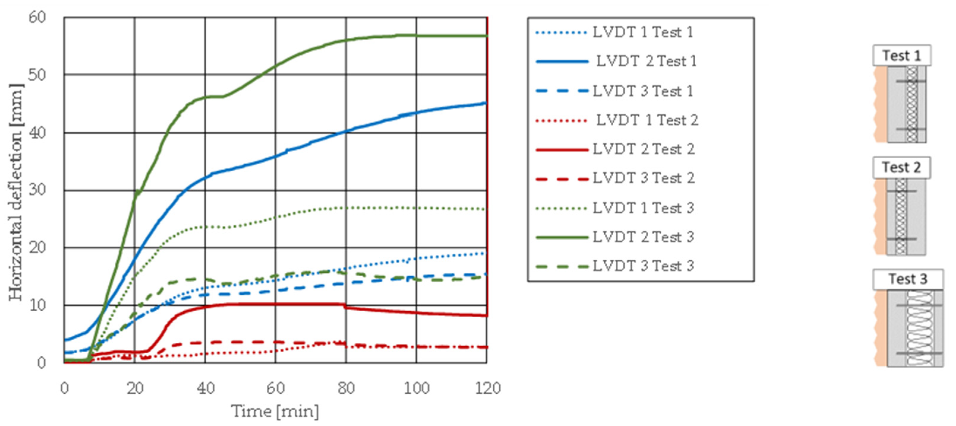
3.3. Out-of-Plane Behaviour
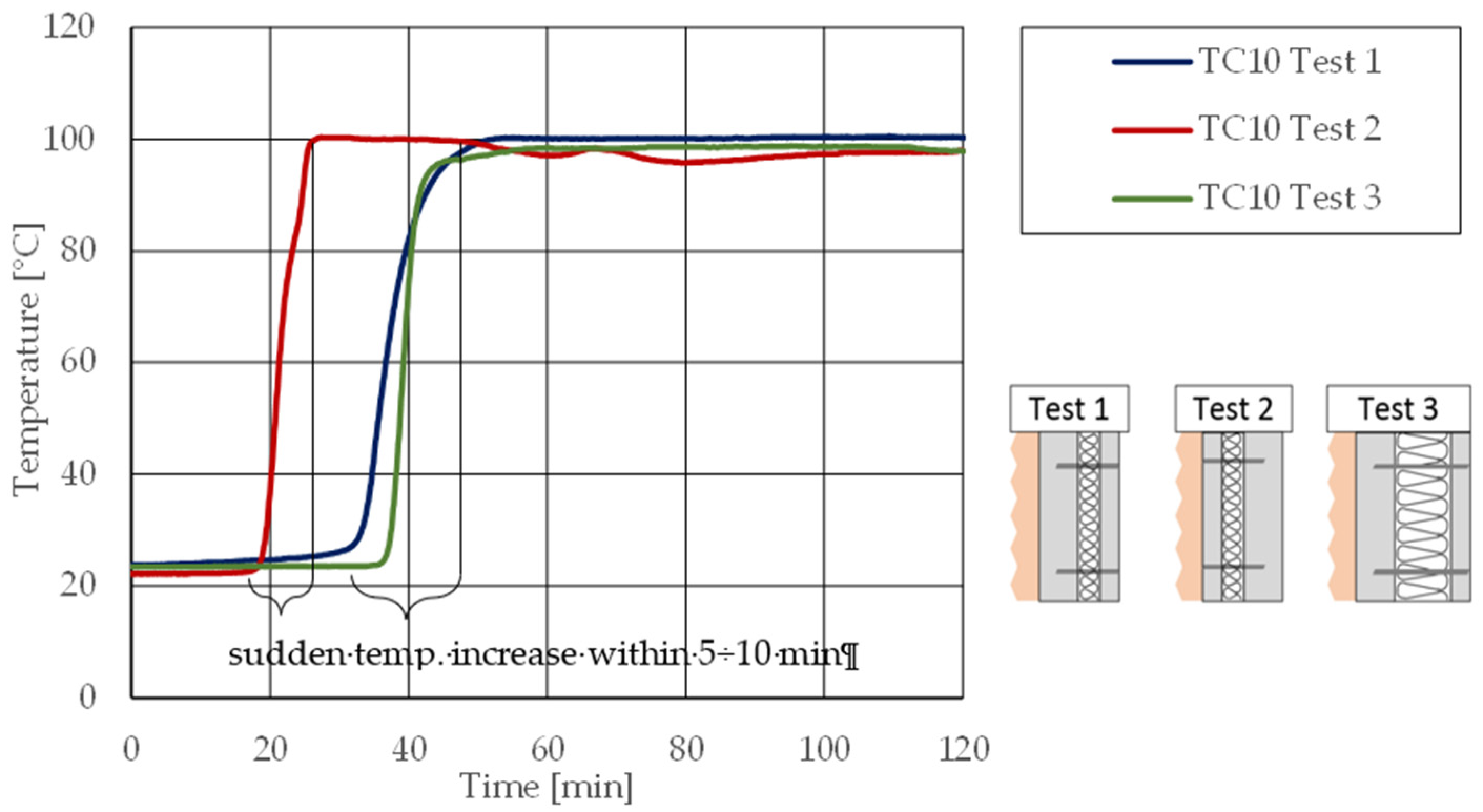
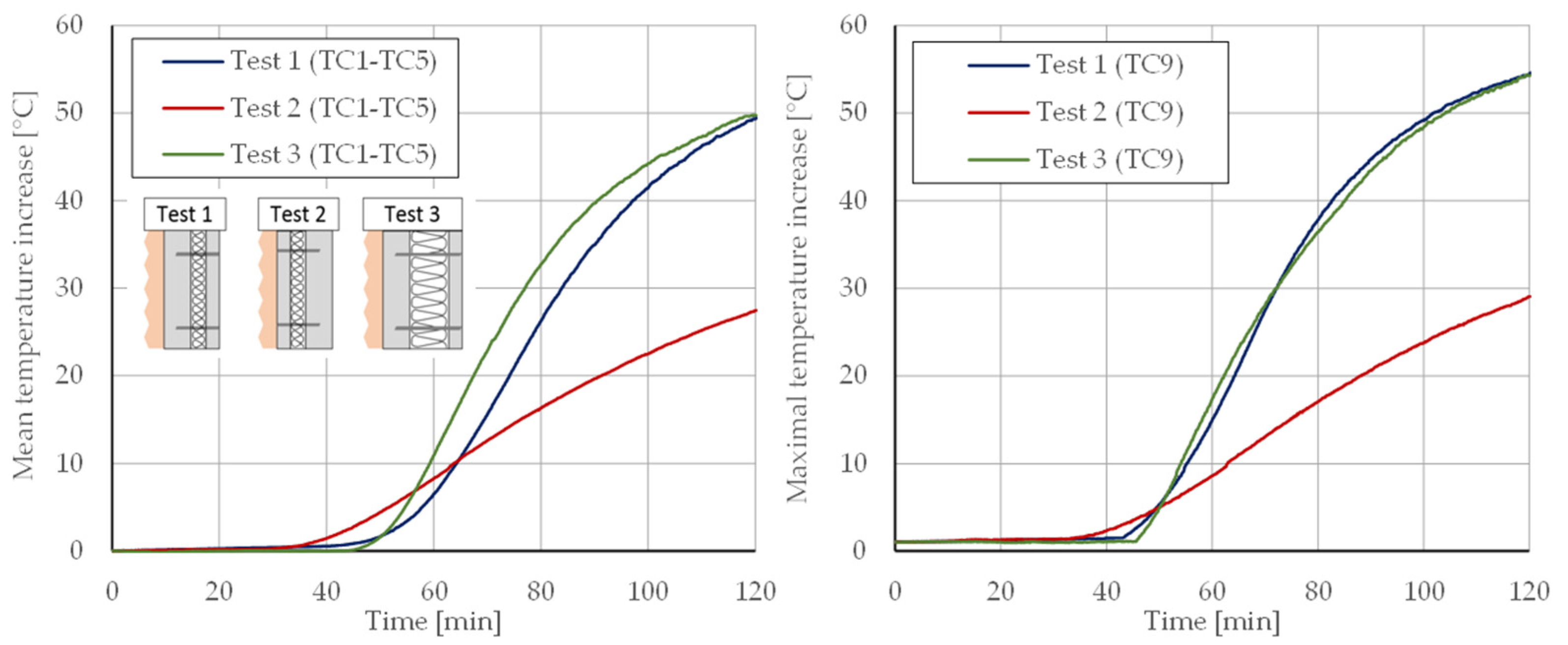
3.4. Heat-Transfer Behaviour
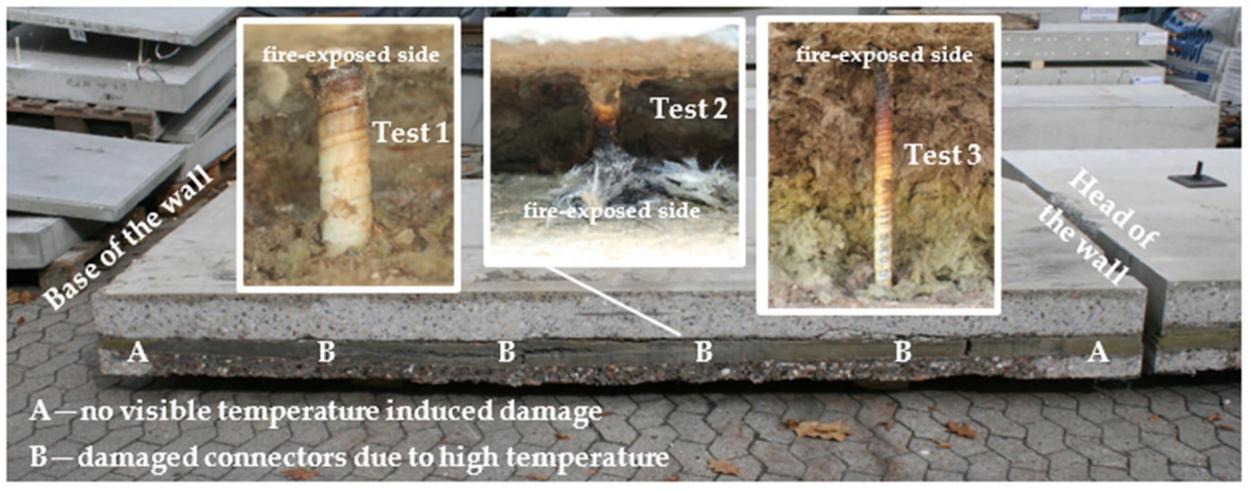
3.5. Connectors and Insulation
3.6. Composite Action
4. Summary and Conclusions
Author Contributions
Funding
Data Availability Statement
Acknowledgments
Conflicts of Interest
References
- Grzesiak, S.; Pahn, M.; Schultz-Cornelius, M.; Bies, N.S. Influence of Different Fiber Dosages on the Behaviour of Façade Anchors in High-Performance Concrete. CivilEng 2021, 2, 556–579. [Google Scholar] [CrossRef]
- Precast/Prestressed Concrete Institute. PCI Design Handbook, 7th ed.; Precast/Prestressed Concrete Institute: Chicago, IL, USA, 2010. [Google Scholar]
- Pahn, M. Beitrag zur Ermittlung von Schnitt- und Verformungsgrößen bei Mehrschichtigen Stahlbetonwandtafeln mit Verbindungsmitteln aus Glasfaserverstärktem Kunststoff. Ph.D. Thesis, Technische Universität Kaiserslautern, Kaiserslautern, Germany, 2011. [Google Scholar]
- Bies, N.S.; Keller, M.L.; Pahn, M. Characterisation of the degradation behaviour of a loaded vinyl ester GFRP bar in alkaline concrete environment. In Proceedings of the 10th International Conference on FRP Composites in Civil Engineering, Istanbul, Turkey, 8–10 December 2021; Ilki, A., Ispir, M., Inci, P., Eds.; Springer International Publishing: Cham, Switzerland, 2021; pp. 714–725. [Google Scholar]
- Keller, M.L.; Pahn, M.; Kopietz, M.; Wetzel, B. Long-term-performance of Loaded GFRP Bars in Alkaline Environment. In Proceedings of the 8th Biennial Conference on Advanced Composites in Construction (ACIC-17), Sheffield, UK, 5–7 September 2017; pp. 97–102. [Google Scholar]
- Fédération Internationale du Béton. Fib Bulletin No. 84. Precast Insulated Sandwich Panels; International Federation for Structural Concrete: Lausanne, Switzerland, 2017. [Google Scholar]
- Schultz-Cornelius, M. Konzept zur Bemessung von Unbewehrten Fassadenplatten aus Ultrahochleistungsbeton in Mehrschichtigen Stahlbetonwandtafeln. Ph.D. Thesis, Technische Universität Kaiserslautern, Kaiserslautern, Germany, 2020. [Google Scholar]
- Schultz-Cornelius, M.; Pahn, M. GFRP Reinforcement and Anchorage Concepts for GFRP Reinforcement and Anchorage Concepts for filigree Energy-Efficient Façades made of UHPC. In Proceedings of the Powerskin Conference|Proceedings 2017, Munich, Germany, 19 January 2017. [Google Scholar]
- Lameiras, R.; Barros, J.A.O.; Valente, I.B.; Poletti, E.; Azevedo, M.; Azenha, M. Seismic behaviour of precast sandwich wall panels of steel fibre reinforced concrete layers and fibre reinforced polymer connectors. Eng. Struct. 2021, 237, 112149. [Google Scholar] [CrossRef]
- Lezgy-Nazargah, M.; Vidal, P.; Polit, O. A 1D nonlinear finite element model for analysis of composite foam-insulated concrete sandwich panels. Compos. Struct. 2019, 210, 663–675. [Google Scholar] [CrossRef] [Green Version]
- EN 13823:2015; Reaction to Fire Tests for Building Products—Building Products Excluding Floorings Exposed to the Thermal Attack by Single Burning Item. Beuth Verlag GmbH: Berlin, Germany, 2015.
- Schmitt, A.; Pahn, M. Investigation on Flexural Stressed Sandwich Panels with GFRP-reinforcement. In Proceedings of the 7th International Conference on FRP Composites in Civil Engineering (CICE 2014), Image Printing at the University of Calgary, Vancouver, BC, Canada, 20–22 August 2014; pp. 164–169. [Google Scholar]
- Schmitt, A.; Carvelli, V.; Pahn, M. Thermo-mechanical loading of GFRP reinforced thin concrete panels. Compos. Part B-Eng. 2015, 81, 35–43. [Google Scholar] [CrossRef]
- Haffke, M.M.; Pahn, M. Flexural behaviour of thin GFRP-reinforced concrete slabs with reduced concrete cover as a part of pre-cast sandwich panels. In Proceedings of the 8th Binnial Conference on Advanced Composites in Construction (ACIC 2017), Sheffield, UK, 5–7 September 2017; pp. 267–272. [Google Scholar]
- Hulin, T.; Hodicky, K.; Schmidt, J.W.; Stang, H. Experimental investigation of sandwich panels using high performance concrete thin plates exposed to fire. Mater. Struct. 2016, 49, 3879–3891. [Google Scholar] [CrossRef] [Green Version]
- Stamm, K.; Witte, H. Aufstellung einer allgemeinen Plattentheorie für Sandwichplatten. HOERSCH-Ber. Aus Forsch. Und Entwickl. 1969, 4, 122–136. [Google Scholar]
- Schmied, J.; Ruff, D.; Ummenhofer, T. Sandwichelemente unter Brandeinwirkung. Stahlbau 2015, 84, 862–865. [Google Scholar] [CrossRef]
- DIN EN 13501-2:2016; Klassifizierung von Bauprodukten und Bauarten zu ihrem Brandverhalten-Teil 2: Klassifizierung mit den Ergebnissen aus den Feuerwiderstandsprüfungen, mit Ausnahme von Lüftungsanlagen. Beuth Verlag GmbH: Berlin, Germany, 2016.
- Schmitt, A.; Carvelli, V.; Haffke, M.M.; Pahn, M. Thermo-mechanical response of concrete sandwich panels reinforced with glass fiber reinforced polymer bars. Struct. Concr. 2017, 19, 839–850. [Google Scholar] [CrossRef]
- DIN EN 1365-1:2013; Feuerwiderstandsprüfungen für Tragende Bauteile—Teil 1: Wände. Beuth Verlag GmbH: Berlin, Germany, 2013.
- DIN EN 1363-1:2012; Feuerwiderstandsprüfungen—Teil 1: Allgemeine Anforderungen. Beuth Verlag GmbH: Berlin, Germany, 2012.
- Deutsches Institut für Bautechnik. Z-33.4-1571: Mineralwolle-Platten MW Wolle 035 (Dämmstoffdicke bis 200 mm); Deutsches Institut für Bautechnik: Berlin, Germany, 2016. [Google Scholar]
- Deutsches Institut für Bautechnik. Z-21.8-1894: Schöck Thermoanker; Deutsches Institut für Bautechnik: Berlin, Germany, 2016. [Google Scholar]
- Rafiq, A.; Al-Qadhi, M.; Merah, N.; Ali, Y. Mechanical Behavior of Hybrid Glass Fibre/Epoxy Clay Nanocomposites. Advanced Materials Research; Trans Tech Publications Ltd.: Bäch, Switzerland, 2014; Volume 894. [Google Scholar]
- Schöck Bauteile GmbH. Technical Information: Schöck Combar®; Schoeck Bauteile GmbH: Baden Baden, Germany, 2015. [Google Scholar]
- DIN 1259-1: 1986 Glass; Terminology Relating to Glass Types and Groups. Beuth Verlag GmbH: Berlin, Germany, 1986.
- Kravchenko, I. E-CR Glass Fibre for High-Performance Composites; JEC-Composites No 16 April 2005; JEC Composites Magazine: Paris, France, 2005. [Google Scholar]
- ISO 834-1:1999; Fire-Resistance Tests—Eements of Building Construction—Part 1: General Requirements. International Standards Organization: Geneva, Switzerland, 1999.
- DIN EN 1363-2:1999; Feuerwiderstandsprüfungen-Teil 2: Alternative und Ergänzende Verfahren. Beuth Verlag GmbH: Berlin, Germany, 1999.
- DIN EN 13501-1:2010; Klassifizierung von Bauprodukten und Bauarten zu ihrem Brandverhalten-Teil 1: Klassifizierung mit den Ergebnissen aus den Prüfungen zum Brandverhalten von Bauprodukten. Beuth Verlag GmbH: Berlin, Germany, 2010.
- Rosa, J.C.; Firmo, J.P.; Correia, J.R.; Mazzuca, P. Influence of elevated temperatures on the bond behaviour of GFRP bars to concrete—pull-out tests. In Report of the IABSE Symposium Guimarães 2019—Towards a Resilient Built Environment Risk and Asset Management; International Association for Bridge and Structural Engineering: Guimaraes, Portugal, 2019; pp. 861–868. [Google Scholar]
- Carvelli, V.; Pisani, M.A.; Poggi, C. High temperature effects on concrete members reinforced with GFRP rebars. Compos. Part B-Eng. 2013, 54, 125–132. [Google Scholar] [CrossRef]
- Mouritz, A.P.; Gibson, A.G. Fire Properties of Polymer Composite Materials; Springer: Dordrecht, The Netherlands, 2006. [Google Scholar]
- Rosa, I.C.; Firmo, J.P.; Correia, J.R.; Barros, J.O. Bond behaviour of sand coated GFRP bars to concrete at elevated temperature—Definition of bond vs. slip relations. Compos. Part B-Eng. 2018, 160, 329–340. [Google Scholar] [CrossRef]


| No. | Compressive Strength | Mean Value | Standard Deviation | |
|---|---|---|---|---|
| - | (Days) | (N/mm2) | (N/mm2) | (N/mm2) |
| 1. | 182 | 57.92 | 55.78 | ±1.95 |
| 2. | 55.27 | |||
| 3. | 56.59 | |||
| 4. | 53.34 |
| Test 1 | Test 2 | Test 3 | |
|---|---|---|---|
| Load-bearing capacity | |||
| Axial height reduction (mm) | |||
| Rate of the axial height reduction (mm/min) | |||
| Deflection (mm) | |||
| Deflection rate (mm/min) | |||
| Thermal insulation | |||
| Mean temperature increase on the side not exposed to fire | |||
| Maximal temperature increases above the initial temperature | |||
Publisher’s Note: MDPI stays neutral with regard to jurisdictional claims in published maps and institutional affiliations. |
© 2022 by the authors. Licensee MDPI, Basel, Switzerland. This article is an open access article distributed under the terms and conditions of the Creative Commons Attribution (CC BY) license (https://creativecommons.org/licenses/by/4.0/).
Share and Cite
Haffke, M.; Pahn, M.; Thiele, C.; Grzesiak, S. Experimental Investigation of Concrete Sandwich Walls with Glass-Fiber-Composite Connectors Exposed to Fire and Mechanical Loading. Appl. Sci. 2022, 12, 3872. https://0-doi-org.brum.beds.ac.uk/10.3390/app12083872
Haffke M, Pahn M, Thiele C, Grzesiak S. Experimental Investigation of Concrete Sandwich Walls with Glass-Fiber-Composite Connectors Exposed to Fire and Mechanical Loading. Applied Sciences. 2022; 12(8):3872. https://0-doi-org.brum.beds.ac.uk/10.3390/app12083872
Chicago/Turabian StyleHaffke, Marcin, Matthias Pahn, Catherina Thiele, and Szymon Grzesiak. 2022. "Experimental Investigation of Concrete Sandwich Walls with Glass-Fiber-Composite Connectors Exposed to Fire and Mechanical Loading" Applied Sciences 12, no. 8: 3872. https://0-doi-org.brum.beds.ac.uk/10.3390/app12083872