
Development of Fuzzy-Adaptive Control Based Energy Management Strategy for PEM Fuel Cell Hybrid Tramway System


School of Mechanical and Automotive Engineering, University of Ulsan, Daehakro 93, Nam-gu, Ulsan 44610, Korea
*
Author to whom correspondence should be addressed.
Appl. Sci. 2022, 12(8), 3880; https://0-doi-org.brum.beds.ac.uk/10.3390/app12083880
Submission received: 12 March 2022
/
Revised: 5 April 2022
/
Accepted: 8 April 2022
/
Published: 12 April 2022
(This article belongs to the Special Issue Energy Management Control and Optimization for Hybrid Electric Vehicles: Volume II)
Abstract
:Currently, the implementation of hybrid proton-exchange membrane fuel cell (PEMFC)-battery-supercapacitor systems for hybrid tramways to replace conventional internal combustion engines and reduce greenhouse gas emissions has triggered an upward trend in developing energy management strategies (EMSs) to effectively deploy this integration. For this purpose, this paper introduces a comprehensive EMS consisting of high-level and low-level controls to achieve appropriate power distribution and stabilize the operating voltage of the powertrain. In the high-level control, a fuzzy logic technique and adaptive control loop are proposed to determine the reference power for energy sources under different working conditions. Meanwhile, the low-level control aims to generate a pulse-width-modulation (PWM) signal for DC/DC converter, associated with each electric source, to regulate the device’s output performance and guarantee the DC bus voltage. Comparisons between the proposed strategy with available approaches are conducted to verify the effectiveness of the proposed EMS through MATLAB/Simulink environment. The simulation results confirm that the proposed EMS not only sufficiently ensures powers distribution even when the abrupt changes of load or high peak power, but also enhance the efficiency of the PEMFC, in which the PEMFC stack efficiency can be exhibited up to 53% with hydrogen consumption less than 21.4%. Moreover, the DC bus voltage can be regulated with a small ripple of around 1%.
1. Introduction
Nowadays, environmental pollution becomes an urgent issue that undoubtedly influences the health of humans and other creatures living in the world. This situation has spurred more studies to come up with renewable energy sources as a long-term solution for human survival. According to research by the International Energy Agency (IEA), from 1990 to 2018, renewable electricity generation rose rapidly with wind, solar photovoltaic (PV), and hydrogen resources. In which, the growth of hydrogen energy increased 97.3% and was forecast to remain the world’s largest source of green energy [1]. It can be seen that hydrogen is one of the essential elements in the energy structure as well as has great potential to be widely used in the 21st century.
As the most proper and effective system using hydrogen, the PEMFC has been attracted as a potential candidate to combine with conventional energy devices such as a battery (BAT) or a supercapacitor (SC) [2] in hybrid systems. The lower operating temperatures and higher energy conversion are the leading properties of the PEMFC in comparison with other types of fuel cells [3]. However, slow dynamic response and incapability of recovering exceeded energy have become the key obstacles for widespread applications that use the PEMFC as a standalone energy source because the variation of load demand may result in fuel starvation, membrane drying issues, blooding; thus, causing the degradation of PEMFC lifetime [4,5,6]. Hence, it is necessary to develop an integration of the PEMFC with other interconnected electrical storage devices such as BAT and/or the SC. For example, the integration of PEMFC with both BATs and SCs was investigated in many applications such as hybrid electric vehicles [7,8], construction machinery [9,10], and hybrid tramway powertrain [11,12], and some other fields of automation or power systems. This hybrid configuration can exhibit better performance, reduce the system size, solve the problem of fuel economy, and prolong the lifespan of energy devices. However, the problem of effective management should be considered for complex hybrid power systems. Therefore, the development of an EMS is required for appropriate energy assignment between the PEMFC and the energy storage system to match the required power of the powertrain.
Following the historical literature for the hybrid tramway’s EMS design, optimization-based methods have been successfully applied in several research works; however, the local optimal solutions of real-time optimizations or inconvenience of off-line computation in global optimizations are existing issues to address when implemented on hybrid systems in practice. Besides, most studies on optimization for the hybrid tramway have been implemented in two-device configurations such as BAT-SC, FC-BAT, and FC-SC because it is a challenge to achieve optimal objects for three-device configurations under complicated power-sharing strategies [13,14,15]. Thus, rule-based EMS can be regarded as a simplified and effective selection to design efficient power distribution strategies for the hybrid system, especially the high-power system such as tramways, excavators, and so on. In [16], a power flow control strategy was developed for a switcher locomotive-powered PEMFC-BAT-SC hybrid system to maintain levels of power demand while keeping the appropriate state of charge (SOC) on the energy storage devices (ESDs). In [17], Garcia et al. presented an adaptive EMS based on states of the PEMFC and BAT to distribute the load power demand for each energy source. This strategy could ensure the power performance and satisfy the driving cycle of the hybrid tramway system under different working conditions. Developed from the work [17], an operational mode control and cascade control loop were carried out in [18]. The simulation results showed that the proposed EMS was able to produce an appropriate power for the traction load while keeping the SOC of ESDs and the DC bus voltage at the desired level. To achieve better efficiency of a hybrid LF-LRV system, Qi Li et al. [19,20] proposed a state machine strategy based on droop control to coordinate multiple power sources following the states of load change. The obtained results confirmed that the proposed algorithm could satisfy the rapid variations of power demand, ensure the steady operation during the most of diving cycle, and enhance overall tramway efficiency. Despite achieving good performance of power distribution, this method remains a drawback of not flexible operation because of switching modes that are usually based on the on/off mechanism to adapt to the particular working conditions. This may cause instability and delay to the system if the order of charge and discharge for ESDs is not appropriate such as power shortage for the hybrid system in the case of a sudden load change.
Considered a powerful tool, the fuzzy logic method has been applied to solve the complex issues of the logical process, especially in the power allocation for the hybrid system. Unlike the classical logic algorithm that requires clear knowledge, accurate equations, and exact numeric data of a system, fuzzy logic combines a different way of thinking, which allows complicated systems to be modeled using a higher degree of flexibility based on human knowledge and experience. In the fuel cell hybrid vehicular system, the fuzzy logic-based approach has been applied to develop the power management strategy in many works. Truong et al. [21] employed the fuzzy logic control (FLC)-based EMS, developed based on the rule-based method from the previous work [22], to satisfy the power demand, reduce fuel consumption and maintain storage devices’ SOC for excavators. For an electric vehicle application, Qi Li et al. [23] used FLC to build EMSs for hybrid FC-BAT and FC-BAT-SC configurations to improve the fuel economy of the car and extend the mileage of the journey. In [24], Ameur et al. exploited the master-slave model-based FLC strategy for an EMS design to improve the system efficiency and prolong the component lifespan for a renewable hybrid system. Ahmadi et al. constructed a fuzzy-based EMS with a genetic algorithm for a PEMFC integrated with BATs-SCs to improve the hybrid vehicle behaviors [25]. The feasibility of the FLC methods for the PEMFC hybrid system-based transportation applications was investigated in some papers [26,27,28,29,30,31,32]. For the hybrid tramway systems, the use of FLC was first recommended by Qi Li et al. [33]. In this work, the multi-level Haar-Wavelet transform was incorporated into the structure of the 2-FLC approach to separate the high- and low-frequency features of the power demand. The results indicated that the proposed strategy achieved high efficiency without compromising the stack efficiency of the PEMFC and coordinated the power demand to each power source appropriately. In [34], Zhang et al. designed a fuzzy controller for a locomotive system with input variables of load power demand and BAT SOC and output variable of the PEMFC required power. The study indicated that using this controller could not only keep the dynamic response of the PEMFC in the optimal region but also satisfy the dynamic requirements of the hybrid system. Besides, it also maintained the BAT SOC between 0.6 and 0.8 during the various operating conditions or quick changes of load. To guarantee an ideal BAT power in an FC-BAT-SC tramway system, Piraino et al. [35] applied the FLC to find out the suitable factor of the BAT. In this strategy, the BAT power, BAT SOC, and SC SOC were input variables while the BAT corrective factor was the output variable. The simulation was implemented with a real driving cycle and the results proved that the suggested strategy not only made a sufficient BAT power to meet sudden and unexpected demand variations but also avoided critical SOC levels of the BAT and SC. Based on the advantages of FLC, Fragiacomo et al. [36] combined this technique and equivalent consumption minimization strategy (ECMS) to design an EMS for the hybrid locomotive. Based on detailed evaluations of stochastic uncertainties in tramway operation, a suboptimal real-time power-sharing technique was proposed to deal with operation uncertainties, enhance fuel efficiency, and guarantee system durability. In this work, the FLC was conducted to coordinate the power flows of energy sources that could adapt to the requirement of load power. In [37], Peng et al. established a fuzzy logic-based differential power compensation module to balance the performance deterioration of the PEMFC and BAT for a hybrid tramway system. In the aforementioned studies, the requirements of power distribution between the PEMFC and ESDs are effectively implemented by using fuzzy logic techniques. Nevertheless, the voltage control scheme of the DC bus was not considered to design, so the output voltage could not be maintained at the desired value. This thing can cause instability and decrease the working performance of the hybrid system.
Based on the literature, although there are more challenges in the design procedure to achieve high efficiency, the fuzzy logic approach is still a good solution to construct an EMS for a hybrid PEMFC-BAT-SC system. This technique can handle most situations of operating behavior and mutual impacts of the charging and discharging process of ESDs to keep the high performance of all energy sources. Motivated from the above analyses and building on our previous work in [38], this paper proposes an EMS to improve the energy efficiency and fuel economy of a hybrid tramway system by using two levels of control. High-level control includes fuzzy logic rules and a bus voltage control loop to define the reference power of PEMFC and BAT. Then, low-level control is utilized to determine the appropriate control signal for converters of PEMFC and BAT. Accordingly, the main contributions of this research can be summarized as follows: Firstly, a new fuzzy logic strategy is designed to determine the sufficient power of the PEMFC based on the status of the BAT SOC and the required power of load under different working scenarios. Then, an adaptive proportional-integral-derivative (PID) control is employed to maintain the DC bus voltage at a steady state by using the BAT. Furthermore, the SOC regulator is constructed to maintain the SOC of BAT within the desired range to protect the BAT from the depth of charge or discharge and prolong the lifespan of the component. Finally, the proposed strategy is conducted and compared to the other completed strategies to verify the effectiveness.
The rest of this paper is organized as follows. The configuration of the hybrid tramway is dedicatedly described in Section 2, and then Section 3 analyzes the proposed energy management strategy comprehensively with high- and low-level control to guarantee the system qualification. Based on the presented strategies, comparative simulations with other approaches are given in Section 4 to validate the effectiveness of the proposed strategy. Finally, Section 5 presents conclusions as well as merits for further developments.
2. Configuration of Hybrid Tramway
2.1. Hybrid Tramway Description
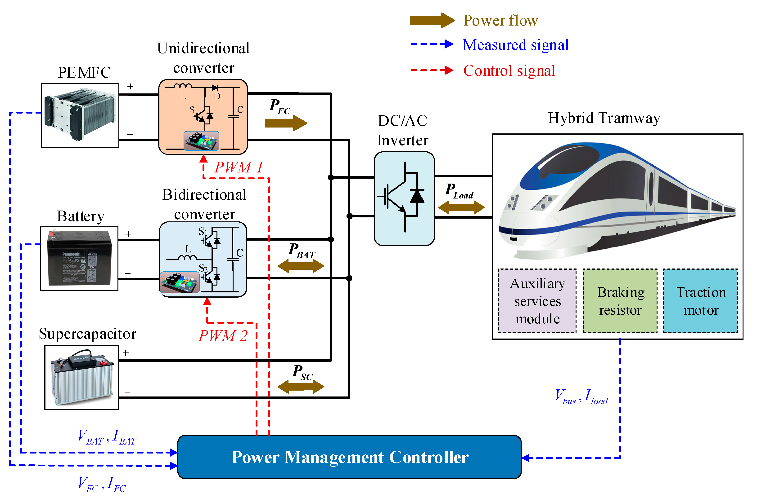
In this work, the hybrid tramway configuration is composed of the PEMFC, the BAT, the SC, the unidirectional DC/DC converter, the bidirectional DC/DC converter, the DC/AC inverter, the traction motor drives, the auxiliary services module, the braking resistor, and the power management controller as described in Figure 1. In this system, the PEMFC serves as a primary energy source and is connected to a unidirectional DC/DC converter to boost the low voltage of the PEMFC to the required voltage of the DC bus. Meanwhile, rechargeable BAT and SC are utilized as ESDs to supplement the insufficient power of PEMFC during the acceleration and cruise processes and absorb the regenerative energy during the braking process. Moreover, the SC is equipped to compensate or consume the peak power of the traction load that the PEMFC and BAT cannot accommodate in a short time owing to its characteristic of fast dynamic response. The PEMFC and BAT are interconnected to the DC bus through unidirectional and bidirectional DC/DC converters, respectively, for energy delivery to the load power demand and recovery tasks to the BAT. The auxiliary devices such as fans, lighting, air conditioning system, etc. are described as the auxiliary services module of the hybrid tramway system. Besides, the braking resistor is also installed to dissipate the energy during regenerative braking if necessary. In order to distribute the power demand, the power management controller is designed to coordinate the power of energy sources by regulating DC/DC converters with charge/discharge mechanisms.
The dynamic model of each component in the hybrid tramway system is defined to simulate the system behavior and evaluate the effectiveness of the proposed EMS. The following subsections outline the specific features of energy sources, DC/DC converters, auxiliary services module, braking resistor, and traction load.
2.2. PEMFC Model
The PEMFC model is the combination of a stack module as a core of the fuel cell system and auxiliary subsystems such as hydrogen delivery, air supplying, humidification, and water-cooling circulation. To construct the dynamic model of PEMFC, the proposed approach in [39] is applied via the MATLAB/Simulink Simscape toolbox, where the effect of reactant flow inside the electrode is neglected to simplify the modeling. In this model, system parameters can be easily set up from the datasheet or by using the simple polarization curve of the testing process.
Considering the PEMFC model in [40] and the evaluation results in [41], the output voltage of each cell is obtained as follows:
where is the cell output voltage (V), is the open-circuit voltage (V), is the activation voltage loss (V), and denotes the resistive and diffusion voltage loss (V).
The open-circuit voltage can be calculated by:
where is the voltage constant at the nominal condition of operation (V) and is the Nernst voltage (V).
The value of activation voltage loss can be defined through [40]:
where A is the Tafel slope (V), is the exchange current (A), is the PEMFC output current (A), and is the cell settling time to a current step (s).
Based on the internal resistance of the electrolyte membrane, the resistive and diffusion losses voltage of PEMFC is expressed as follows:
where is the internal resistance (Ω).
The output voltage of the PEMFC stack is derived according to the number of cells as the following equation:
where is the output voltage of the PEMFC stack (V) and N is the total number of cells.
The output power of the PEMFC stack is obtained by [27]:
where is the supplied power of the PEMFC stack (W) and represents the efficiency of the PEMFC stack.
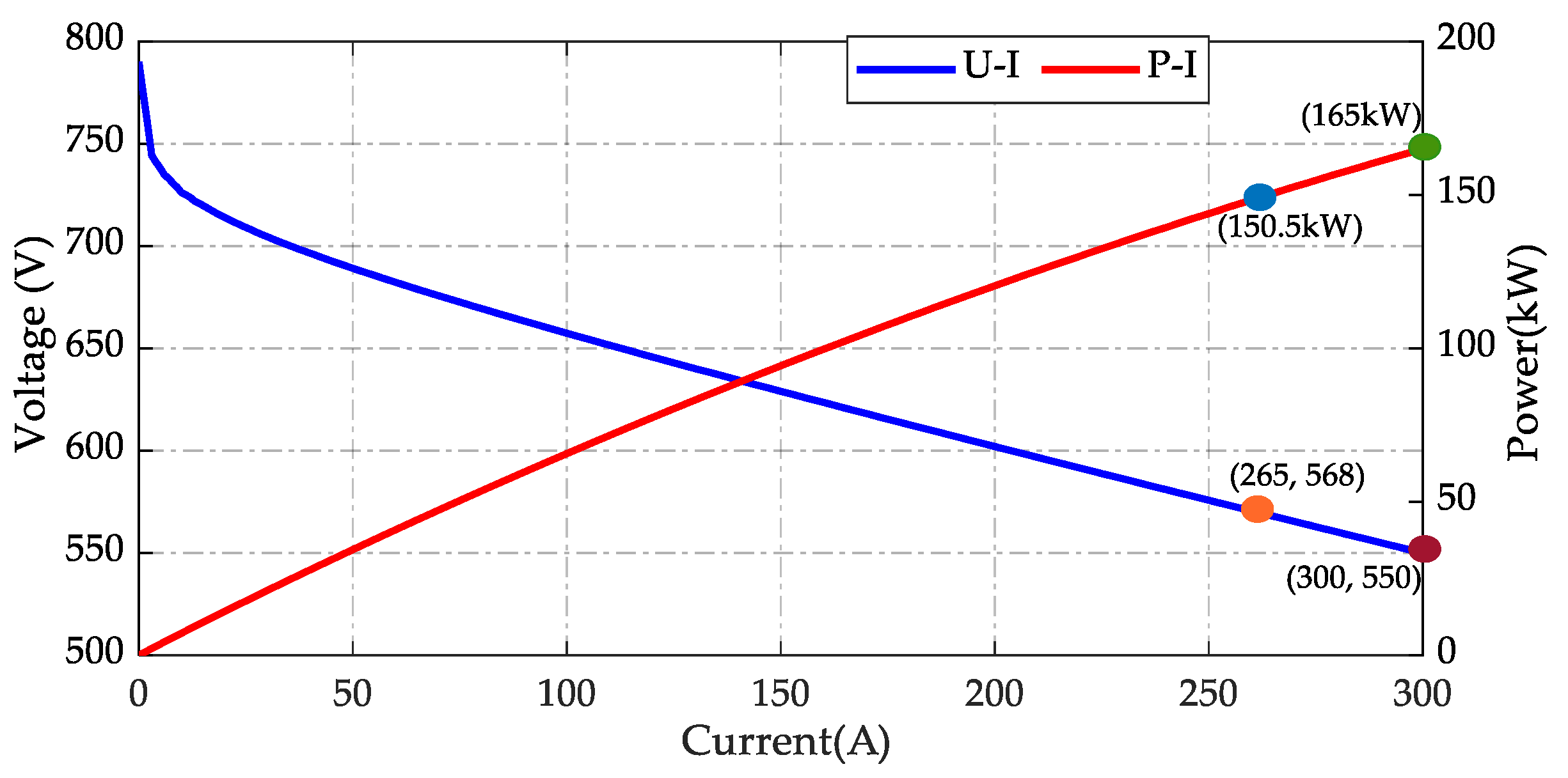
Based on input parameters of the PEMFC model, simulated polarization curves of stack voltage-current (U-I) and stack power–current (P-I) are obtained, as shown in Figure 2.
2.3. Energy Storage System
2.3.1. Battery Model
In the hybrid system, the BAT, with high energy density, more efficient, and faster dynamic response than the PEMFC, is utilized to not only compensate for the excess power that PEMFC cannot deliver but also accumulate the regenerative energy from traction load. The behavior of the BAT model is constructed by using the SimPowerSystems of MATLAB/Simulink with the Shepherd curve-fitting model employed [42]. Depending on the charge mode or discharge mode, the charge model or discharge model is respectively operated to keep the BAT’s capacity in a reasonable operating performance range.
In the discharge model, the term polarization voltage is added to the discharge voltage formulation to describe the influence of BAT SOC on power efficiency. Besides, the polarization resistance is also considered to ensure the stability of the simulation model. Thus, the BAT voltage is calculated as follows [42]:
where is the BAT voltage (V), is the BAT constant voltage (V), K is the polarization constant (V/Ah), Q is the maximum BAT capacity (Ah), is the BAT output current (A), is the low-frequency current dynamics (A), is the exponential zone amplitude (V), B is the exponential zone time constant inverse (Ah−1), and is the BAT internal resistance (Ω). In addition, the term indicates polarization voltage and is the polarization resistance.
For the charging model, the polarization resistance term is adjusted to illustrate the behavior at the end of the charging process because the BAT voltage increases rapidly. In this case, the BAT voltage is represented as follows [42]:
On the other hand, the SOC level of the BAT must be kept in a limited range of capacity to achieve high working efficiency. This SOC can be calculated by the relationship of the current charge and the maximum capacity as [42]
where is the SOC of the BAT (%), t is the instant time, and is the initial time.
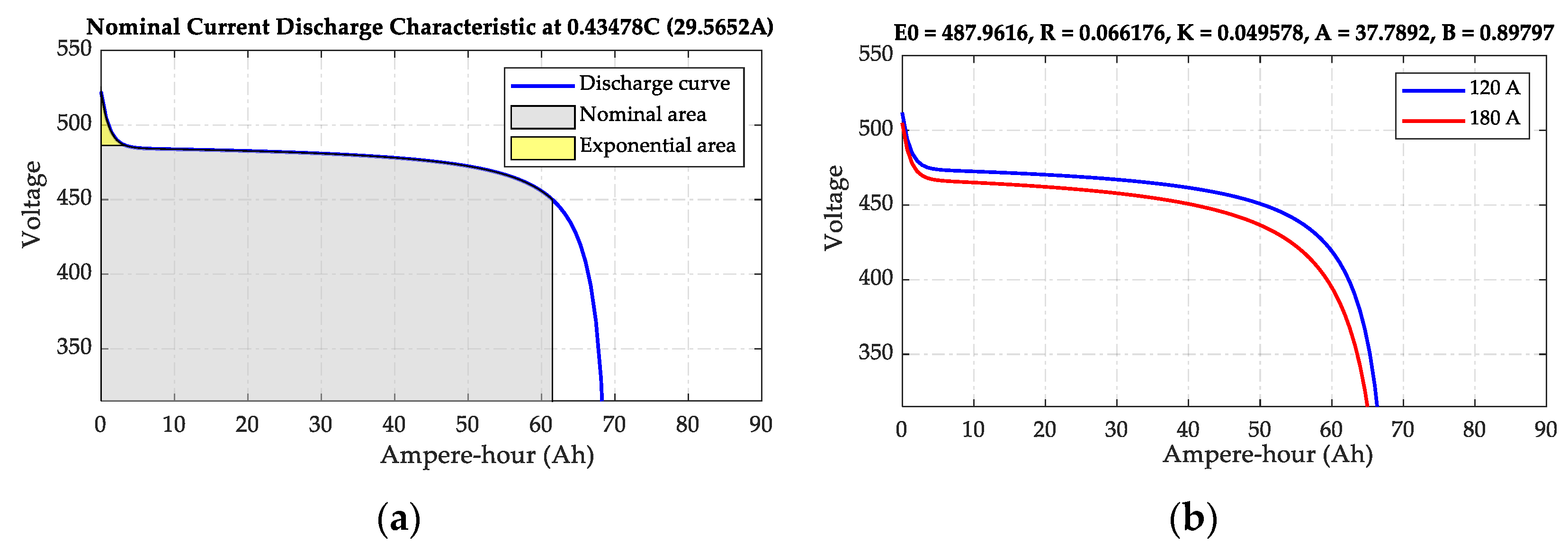
From input parameters, nominal current discharge curves of the used BAT model are obtained as depicted in Figure 3.
2.3.2. Supercapacitor Model
The SC is an electric component that can store and release fast power due to its high capacitance. In the hybrid system, SC is used to supply the peak during the load surge. The SC voltage can be given by [41]:
where is the voltage of SC (V), denotes the SC current (A), is the SC resistance (Ω), represents the total capacitance (F), and is the total electric charge (C).
In this work, the Stern model [43] is applied to build the SC model by using the Simscape toolbox. The total capacitance with an SC bank of cells is defined as follows:
where is the total number of SC cells and C is the capacitance (F) of a cell that can be expressed as [43]
where and are the Helmholtz and Gouy–Chapman capacitance (F), respectively.
Next, the total electric charge is formulated by:
Furthermore, the SOC of the SC is estimated via the current and the maximum capacity. This SOC value is computed as [43]:
where denotes the SOC of SC (%) and represents the maximum SC capacity (Ah), t is the instant time, and is the initial time.
2.4. DC/DC Converters Model
In the hybrid system, the voltage of energy sources alters depending on their required currents or SOC levels. In this case, a DC/DC converter is needed to control the output current that powers the traction load and maintain the DC bus at a constant voltage. Based on the load power demand, the boost or buck mode of the converter is activated. The boost mode is employed to convert the lower voltage on the energy source side to the higher voltage on the DC bus side and buck mode is vice versa. For ESDs such as the BAT and SC, the bidirectional mode is utilized to transform the voltage in two directions between energy sources and the DC bus with the boost mode for discharging operation and the buck mode for charging operation.
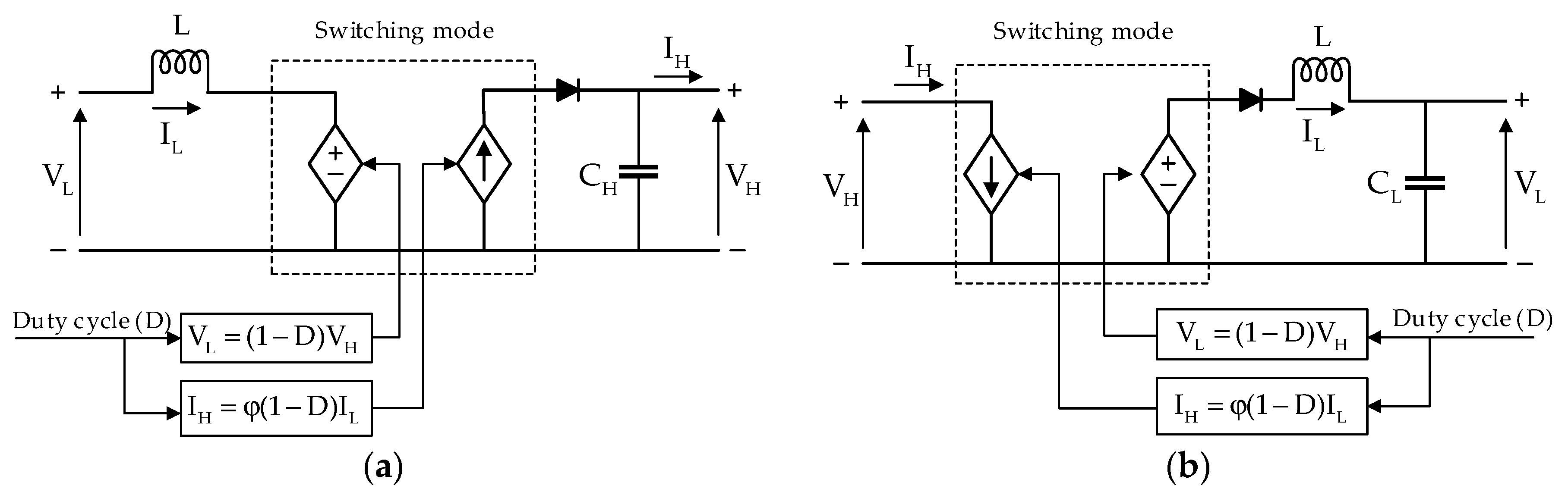
In terms of system modeling, the switching model and average-value model are two types of DC/DC converter models that are usually used for simulation purposes. In the first model, it requires low sampling time to recognize switching actions; thus, consuming more time in the simulation process. Besides, switching harmonics and losses of switching components must be concerned to guarantee the stability of the converter. On the contrary, the average-value model uses controlled voltage/current sources to create switching models that replace switching components. The advantage of this model is that it ignores switching harmonics and spends less time simulating the hybrid system, but all the converter characteristics are still retained. In this paper, the average-value model of the DC/DC converter is selected to generate the desired voltage and current for the switching model. The structures of DC/DC converters based on the average-value model are shown in Figure 4 [41,44].
Where D is the duty cycle (%), is the inductance (H), is the positive gain, and are the capacitance at the low side and high side of the converter (F), respectively; and are the voltage at the low side and high side of the converter (V), respectively; and are the current at the low side and high side of the converter (A), respectively.
2.5. Breaking Resistor
During the braking process, most of the regenerative energy is stored in the ESDs to provide for traction load requirements. However, when the ESDs are unable to absorb all of the regenerative braking energy, a portion of it must be burned throughout the braking resistor. In the fact that the control system decides the activation of this resistor to dissipate the power if the ESDs achieve their maximum charge power.
2.6. Tramway Loads
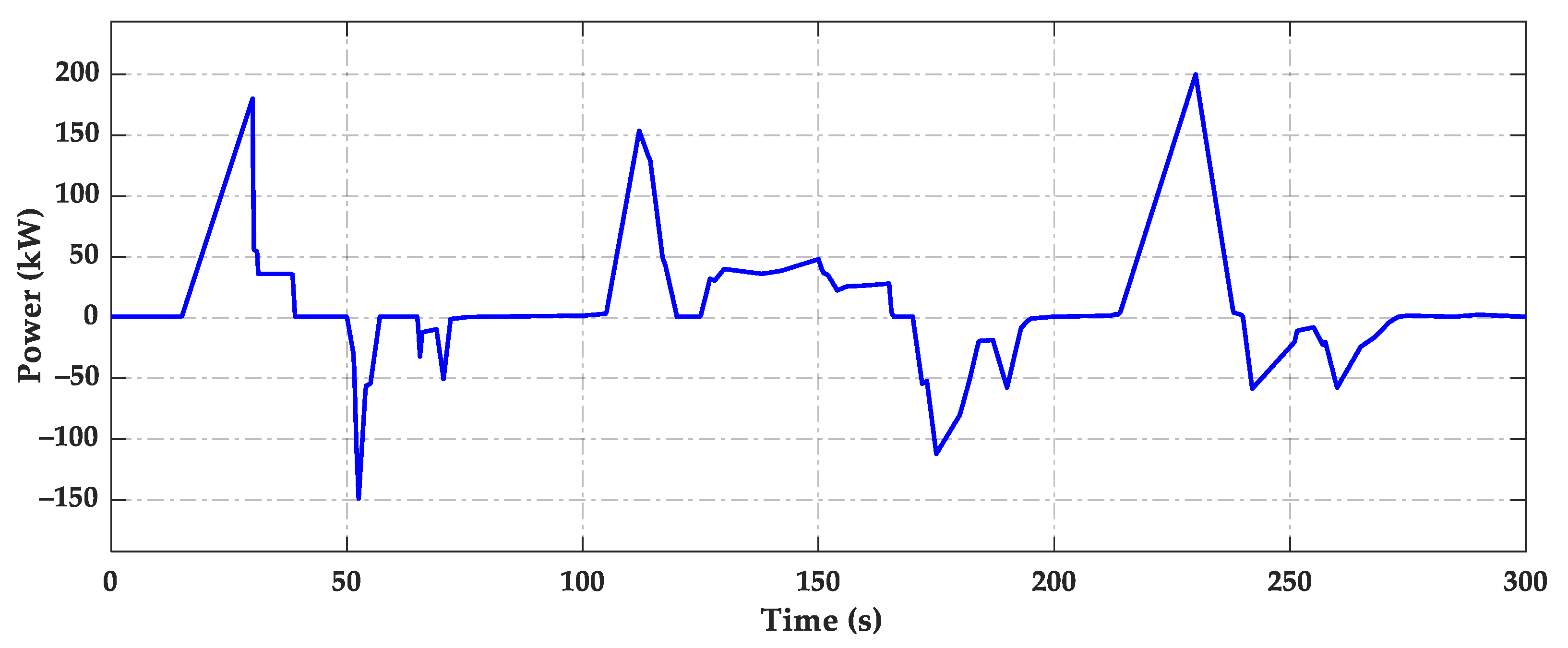
In this hybrid system, auxiliary services and traction power demand are considered as tramway loads. Because the goal of this research is to assess the effectiveness of the proposed control method for the tramway’s EMS, in which the required current is determined through the power consumption and DC bus voltage. The power demand of traction load, obtained from the driving cycle in five minutes recorded under different working conditions [19,20,33,45], is presented in Figure 5.
3. Energy Management Strategy
3.1. Previous EMSs
3.1.1. Rule-Based EMS (RB-EMS)
In the work presented in [18], the RB-EMS was designed based on an operation mode control (OMC) and cascade control loops to generate a reference PEMFC power, guarantee the power demand of the load traction motor, maintain the BAT SOC at the desired value, and keep DC bus voltage at the rated value. This OMC was separated into three operation modes depending on the BAT SOC: discharge mode (high SOC), charge mode (normal SOC), and fast charge mode (low SOC). Two hysteresis cycles were considered to make changes between these modes. Besides, the PI controllers were applied to produce the duty cycles of the converters that regulated the power of energy sources in accordance with the reference powers defined by the EMS. However, this EMS has simple logical rules that can not consider the system’s operating states completely, especially in the case of abrupt changes of load power. In addition, the challenges of fuel economy are not recognized.
3.1.2. Equivalent Consumption Minimization Strategy (ECMS)
Based on the powertrain configuration in [44], a simplified ECMS was employed to define the optimal PEMFC power by finding an optimal solution with the cost function as follows:
where F is the cost function, is the penalty coefficient, is the sampling time (s), and are the PEMFC power and BAT power (W), respectively.
Equality constraints were given by:
with boundary conditions as
where was the load power demand (W), was a constant (<0.6) to handle the BAT SOC range, and were the minimum and maximum BAT SOC level (%), respectively; and were the minimum and maximum PEMFC power (W), respectively; and were the minimum and maximum BAT power (W), respectively.
This approach illustrates high energy management efficiency during the overall driving cycle and minimizes hydrogen consumption. However, the unknown operation points of the PEMFC and BAT lead to challenges in determining the equivalent values of fuel consumption as well as consuming more computing time, resulting in an unstable system under abrupt changes in operating modes.
3.2. Proposed EMS
In the PEMFC hybrid system, designing an algorithm to achieve optimal performance of the PEMFC is realistically regarded as the major requirement. In this work, the proposed algorithm is developed to enhance the PEMFC efficiency, minimize hydrogen consumption, and maintain the BAT SOC () in the range of as a way to prolong the lifespan of the energy device. The overall proposed control strategy is described in Figure 6.
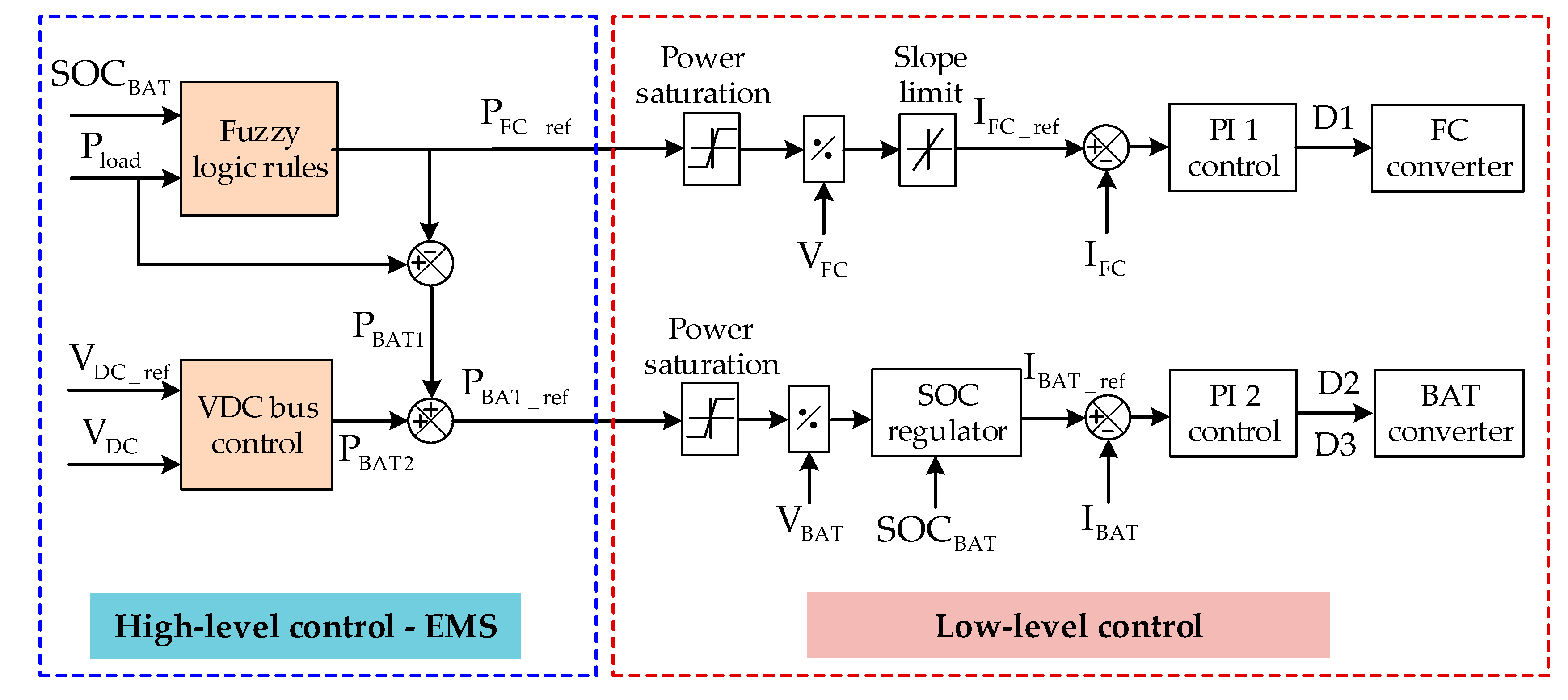
In Figure 6, the proposed EMS consists of two parts: high-level control and low-level control. In the high-level control, the obtained power of the driving cycle is a positive value when the system operates in the acceleration mode or normal mode, whereas this power is a negative value if the system works in regenerative mode. Based on the load power demand () and the , fuzzy logic rules (FLRs) are applied to generate the reference PEMFC power (), which not only provides power for the traction load but also maintains the SOC level of BAT within a certain range. Additionally, the DC bus voltage is also regulated at 750 V by using an adaptive PID controller that determines the battery power . The term is calculated as the difference between the expected load power and the PEMFC reference power. As a result, the reference BAT power () is defined by the total of and . For the low-level control, the duty cycle of each DC/DC converter is decided by a PI controller that depends on the obtained reference powers.
3.2.1. High-Level Control
In the proposed strategy, FLRs are realized by the following parts: fuzzification interface, reasoning machine, rule base, and defuzzification interface with the fuzzy module provided by Matlab/Simulink. The FLR’s objectives are to increase the PEMFC efficiency and minimize hydrogen consumption as well as maintain within the desired range of 0.6~0.9.
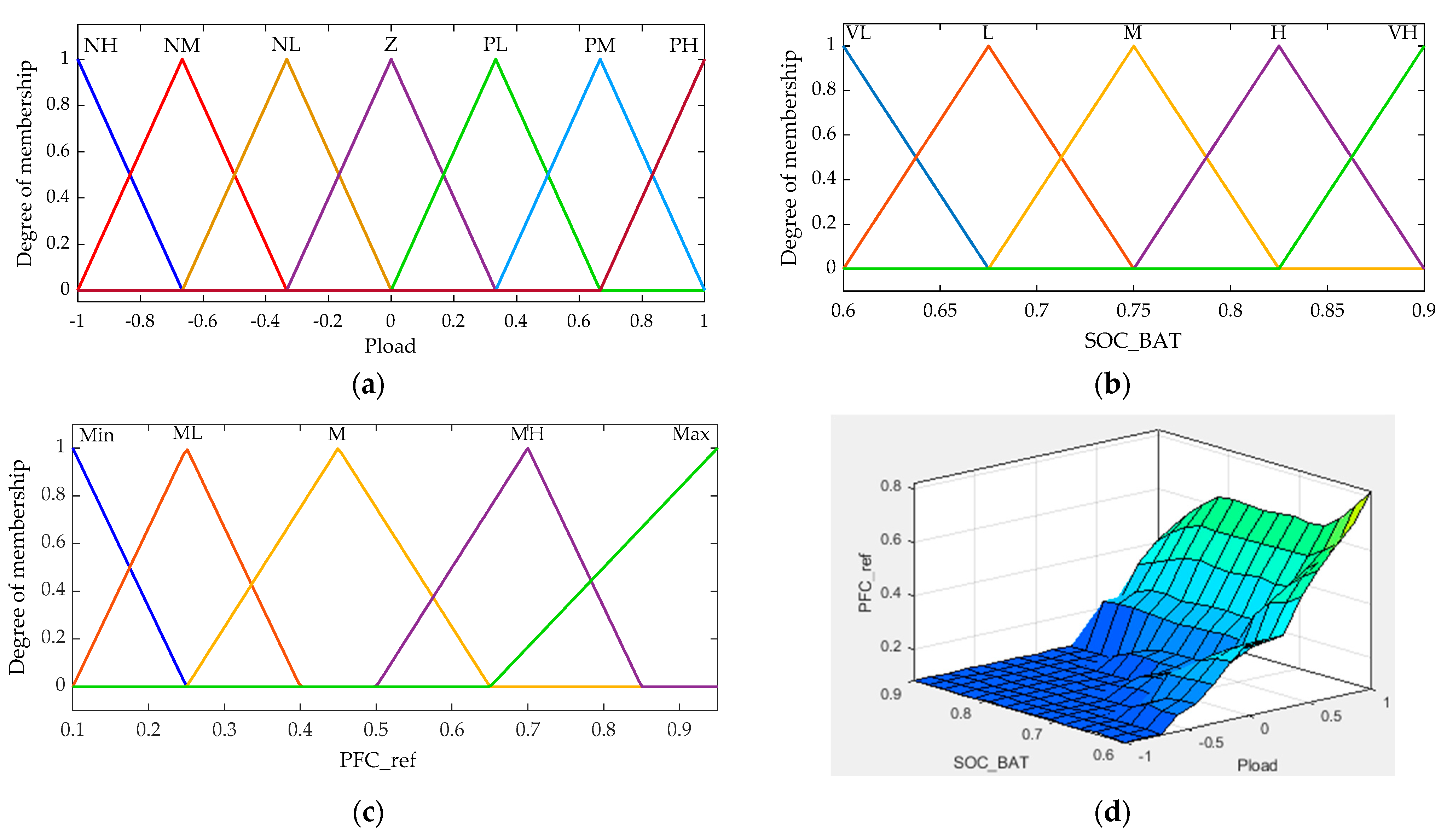
The FLRs are inherited from previous our study in [38], which are composed of two input variables () and one output variable (). The input linguistic has seven membership functions (MFs) including NH (Negative High), NM (Negative Medium), NL (Negative Low), Z (Zero), PL (Positive Low), PM (Positive Medium), PH (Positive High) with the fuzzy field scope [−1, 1]. The input is characterized by five MFs as VL (Very Low), L (Low), M (Medium), H (High), and VH (Very High) within the range of [0.6, 0.9]. The output is defined through five MFs including Min (Minimum), ML (Medium-Low), M (Medium), MH (Medium-High), and Max (Maximum). The inhomogeneous MFs of inputs and output are presented in Figure 7a of MFs for , Figure 7b of MFs for SOCBAT, and Figure 7c of MFs for reference PEMFC power. The operating mode of the FC is defined regarding its MFs and rule table (Table 1), with the Mamdani Inference method applied for conducting the fuzzy reasoning rules.
During the operation, the proposed EMS appropriately distributes the required power to each energy source to not only sufficiently satisfy the workload demand but also maintain the SOC supplement. These parameters should be properly determined to avoid the state of overcharging or deep discharging. For the charging process, if the BAT has high SOC, the injected power is lower and vice versa. Meanwhile, in the discharging process, if the is at a high level, the BAT will release more output power and vice versa. Furthermore, if the SOC capacity of the BAT reaches the upper bound or lower bound, the disconnected action is executed and this device will wait for the next discharging or charging process, respectively.
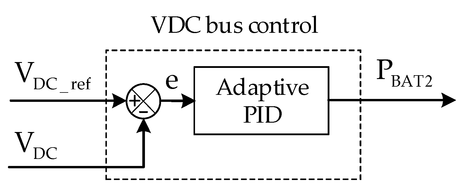
Besides the power distribution requirements, DC bus voltage control is also a critical challenge for maintaining the system’s stability because of voltage fluctuation in the DC bus when load power increases or decreases abruptly. Thus, an adaptive PID controller is designed to control the bus output voltage, as shown in Figure 8 [38].
Herein, the deviation between a reference DC bus voltage () and the measured DC output voltage () is used as an input value of the adaptive PID controller to generate the BAT power . The formulations of this controller are given by [38]:
where e is the differential value, and denote estimated adaptive gains, and are tunable positive gains, is an arbitrarily small positive constant to avoid singularity, and γ is an arbitrary constraint to regulate the DC bus voltage to the vicinity of the reference. It is noteworthy that and are bounded by the predetermined upper positive constant and , respectively, to avoid an over-estimated problem.
3.2.2. Low-Level Control
From the determined PEMFC reference power in the high-level control, the corresponding PEMFC reference current can be systematically deduced for low-level control implementation. As the PEMFC characteristic of slow dynamic, a slope constraint must be applied to regulate the changing rate of this command signal. For instance, the PEMFC takes less than 2 s to increase its output from 10% to 90% of the power rating [18]; hence, the slope constraint is considered to practically realize the PEMFC behavior. For the BAT behavior, the reference current is defined based on the reference power obtained in the high-level control and a SOC regulator scheme that is installed to maintain the SOC level of BAT within the desired range (), as presented in Figure 6. Because the tramway systems usually operate under high power for a long period, BAT conditions should be handled to deal with the SOC variation or prevent the degradation of BAT capacity. Hence, the reference BAT current is calculated based on the SOC status as follows [46]:
where is the reference BAT current (A), denotes the reference BAT power (W), depicts the measured BAT voltage (V), is the SOC level of the BAT (%), and are the tuning parameters, and are the minimum and maximum allowable SOC of the BAT (%), respectively.
Based on the SOC level of the BAT, the above tuning parameters are described as [38]
where and are positive constants depending on charging or discharging characteristics of the BAT.
Duty cycles of the DC/DC converters are generated by using the PI controllers as in Figure 6. In detail, the PI-1 controller produces the duty cycle D1 to control the DC/DC converter of the PEMFC source. Similarly, the PI-2 controller is employed to generate duty cycles for the bidirectional DC/DC converter of the BAT source, in which duty cycle D2 handles the buck mode and duty cycle D3 realizes the boost mode operation.
4. Simulation Results
In this section, a comparative simulation between the proposed strategy and previous methods is conducted to evaluate the strategy’s effectiveness for the hybrid PEMFC-BAT-SC tramway system under different operating conditions. In detail, the proposed fuzzy EMS (F-EMS) was implemented and compared with the two other strategies: an RB-EMS in [18], and an ECMS in [44].
To comprehensively investigate EMS approaches with various operating situations, the load profile as in Figure 5 was considered with several load levels such as acceleration, deceleration, and regeneration in practical working conditions. In addition, the modeling of the hybrid tramway was deployed in Matlab/Simulink 2019b environment with a sampling time for displaying simulation results at 0.1 ms. By reasonably selecting components, characteristics of energy sources and parameters of the proposed EMS are listed in Table 2, Table 3, Table 4 and Table 5.
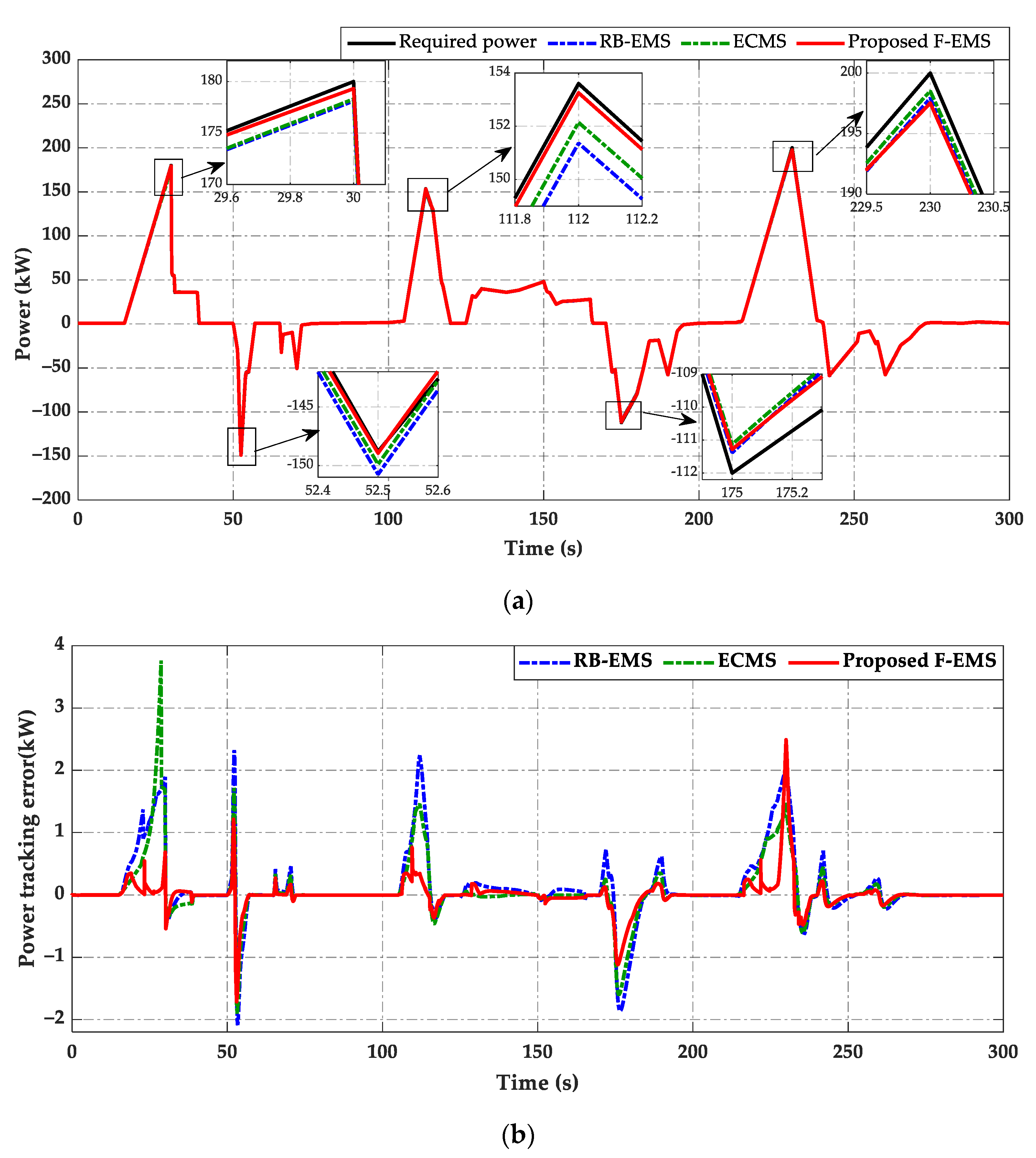
The system qualification is described in Figure 9, Figure 10, Figure 11, Figure 12 and Figure 13. Firstly, simulation results of load power adaptation by using three EMSs are shown in Figure 9 in which a continuous black line represents the required power of load, a continuous red line depicts the output power of the proposed F-EMS, the power of RB-EMS is shown by a dashed-dot blue line, and the power of ECMS is described as a dashed-dot green line. As can be seen in Figure 9a, the required power of the proposed F-EMS satisfies load requirements better than the RB-EMS and ECMS at each time of transient peak power. Although the PEMFC, with the lowest dynamics, cannot instantly react to the load change, the load tracking effort can still be ensured due to the compensation from the BAT and SC during various working modes. In Figure 9b, the ECMS takes an insufficient power in the range of kW, while the RB-EMS obtains a smaller error approximated kW, and the proposed F-EMS achieves the highest distributed accuracy within kW. Furthermore, the proposed F-EMS has the lowest average inadequate power on the driving cycle of the hybrid system. This reveals that the suggested methodology is able to guarantee the load power demand under different operating conditions.
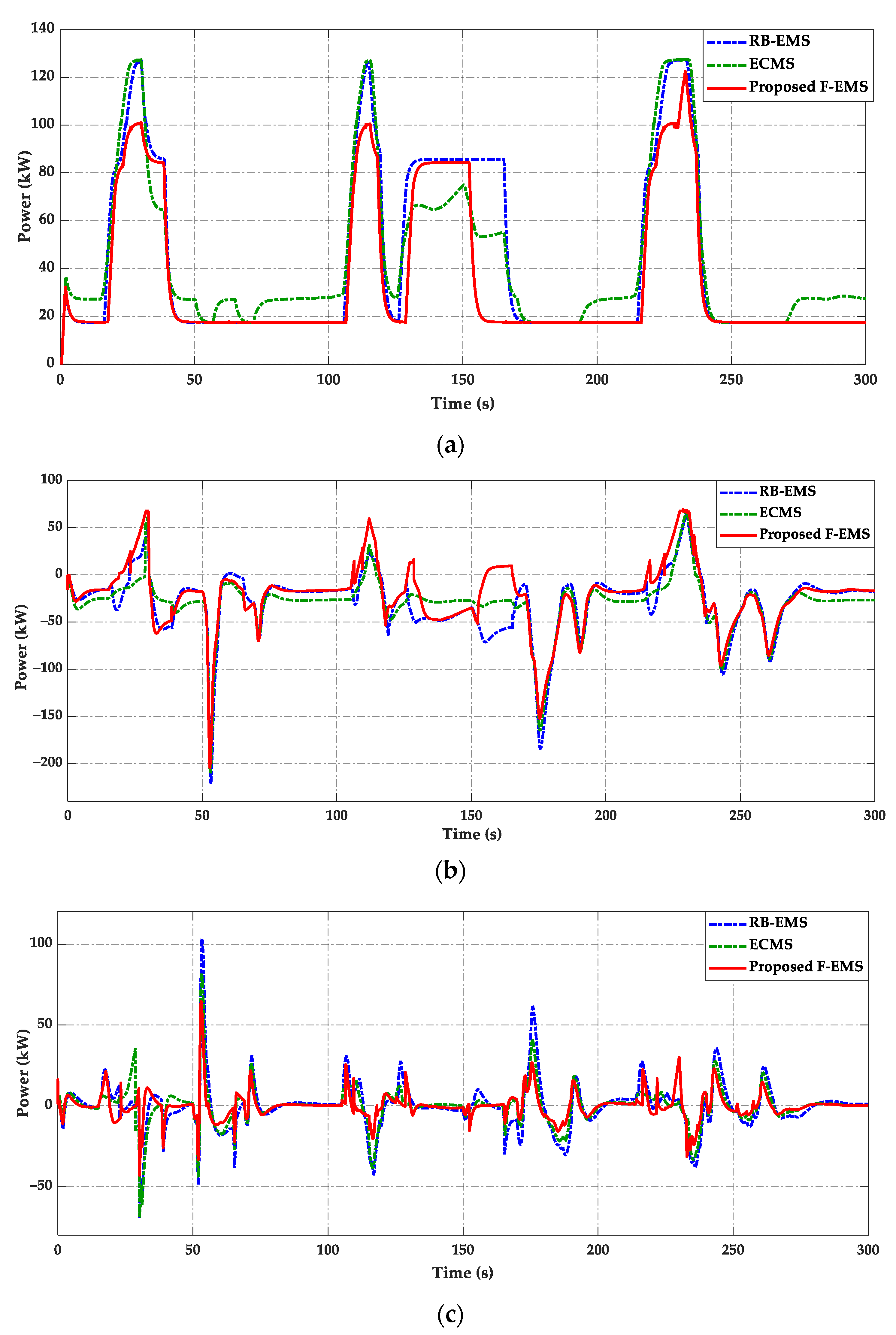
Power distributions of the PEMFC, BAT, and SC under three comparative EMSs are presented in Figure 10. As expressed in Figure 10a, the PEMFC powers of the RB-EMS and ECMS have a high power level that can diminish the aging and performance of the PEMFC system. Meanwhile, the proposed F-EMS provides a better performance indicator with a suitable change rate of PEMFC power and smaller power fluctuation, which can improve the fuel economy and durability of the PEMFC system. The power capability of the BAT under three EMSs is depicted in Figure 10b. It can be seen that the BAT power of the proposed strategy is higher than those of both the RB-EMS and ECMS during the period of acceleration. This is because the output power of the PEMFC when using the proposed F-EMS is lower than the other methods, thus the BAT power must be more discharged to compensate for the lacking power from the fuel cell source to match the load power demand. However, in the regenerative mode, the proposed F-EMS can provide a smooth power response to charge the redundant power from the DC bus to the BAT. The comparative result of the SC power distribution is illustrated in Figure 10c. Due to the fast power response, the SC is employed to supplement the slow power response of the PEMFC and BAT to power the load. As a result, the proposed algorithm regulates the SC power in a suitable range that can accommodate abrupt power of load and reduce power fluctuation of the PEMFC and BAT despite the rapid load change.
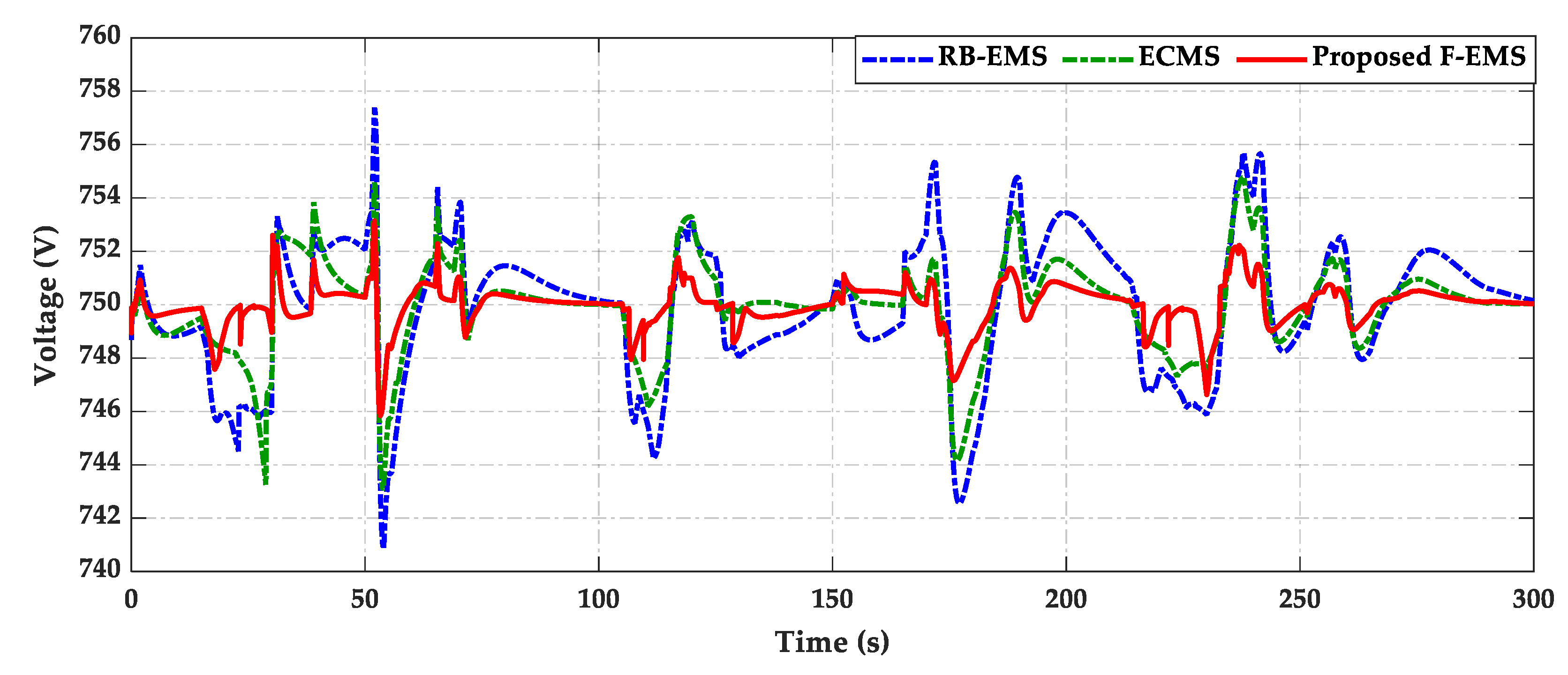
The comparison of DC bus voltage corresponding to the load power demand is shown in Figure 11. By using the proposed F-EMS, the DC bus voltage is steadily maintained at around 750 V with a smaller fluctuation than using the RB-EMS and ECMS. In the change interval of the load, the DC bus peak voltage is in the range of V, approximated by a 1% voltage ripple, by using the proposed F-EMS. This result is better than the ones under the RB-EMS with the range of V and ECMS with the range of V.
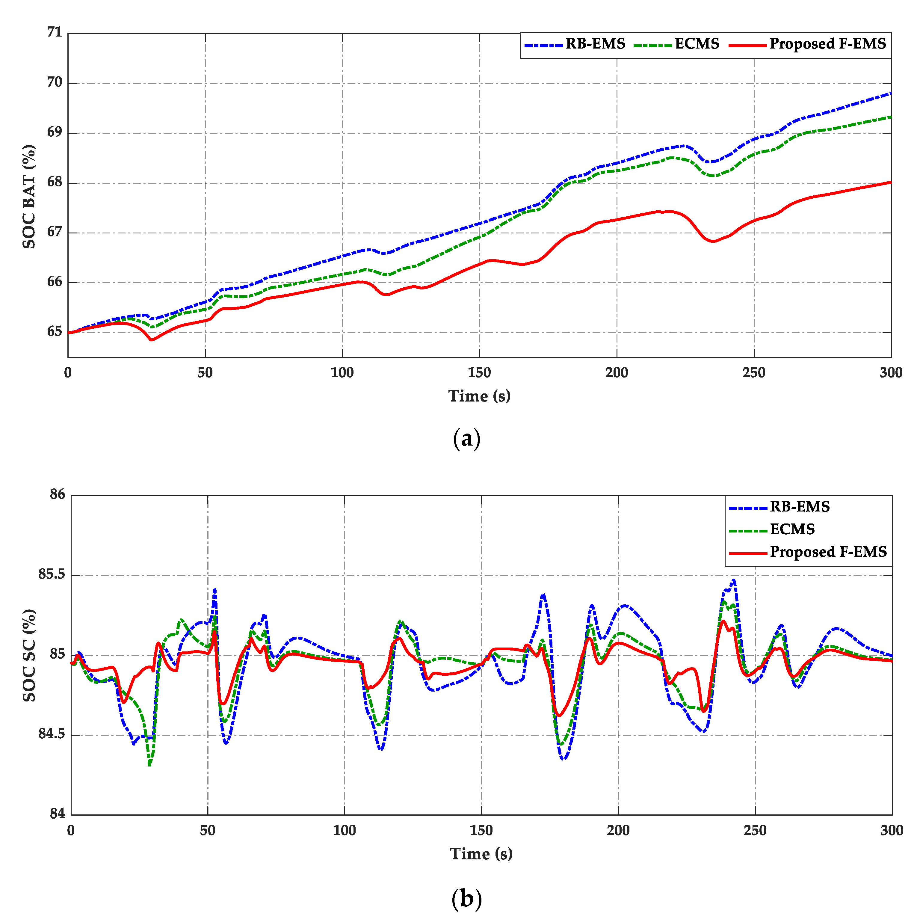
Simulation results of both BAT and SC SOC are shown in Figure 12, which describes the charge and discharge status at each timeline when the load changes. In Figure 12a, the suggested F-EMS can maintain the increasing range of BAT SOC lower than the RB-EMS and ECMS. For the SC, Figure 12b shows that the SOC level varies around 85%. Herein, the proposed approach achieves a SOC varying range within % that is lower than the ECMS with the range of %, while RB-EMS has a large fluctuation in %.
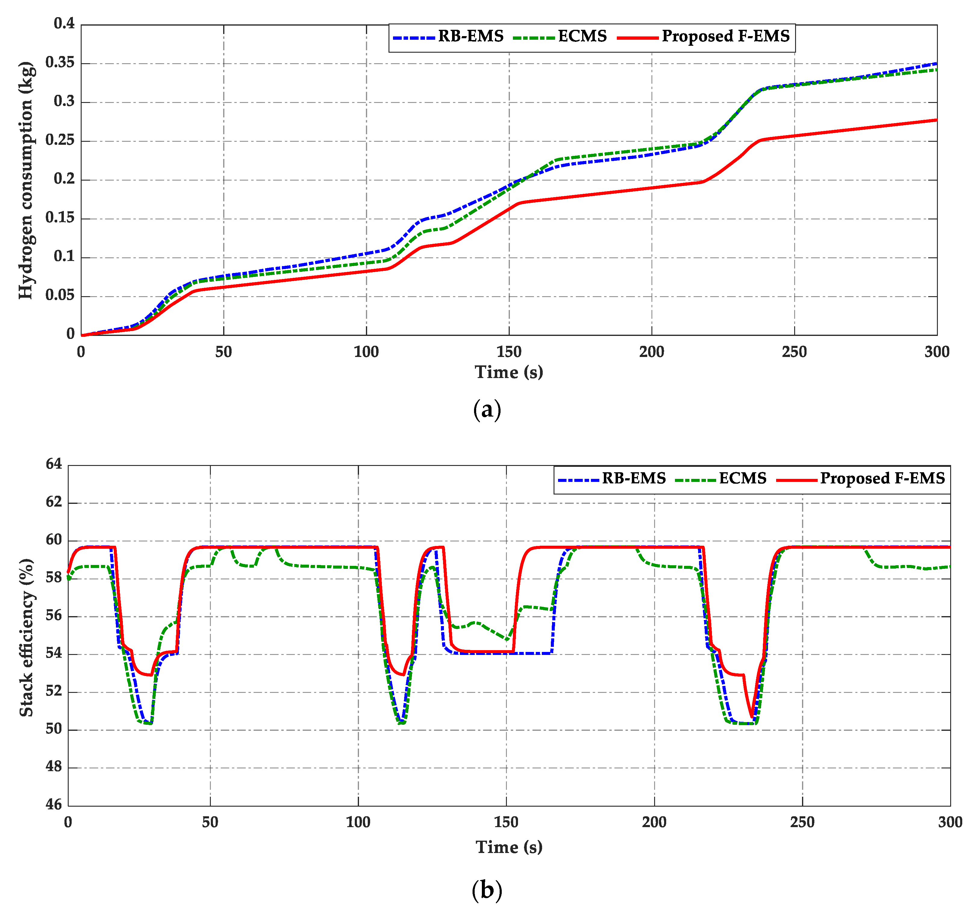
The hydrogen consumption and the PEMFC stack efficiency of three EMSs are described in Figure 13. As a result, the proposed F-EMS consumes lower hydrogen fuel than the RB-EMS and ECMS as presented in Figure 13a. In the case of the proposed strategy, the average amount of hydrogen consumption is 0.275 kg during the time of the driving cycle, whereas the total fuel consumption of the RB-EMS and ECMS reaches 0.35 kg in the same working conditions. It proves that the proposed approach gives better fuel economy with the hydrogen consuming less than 21.4% in comparison with other approaches. Furthermore, with the same driving cycle, the PEMFC stack efficiency of three EMSs is evaluated as well. As shown in Figure 13b, the PEMFC stack achieves an efficiency from 53% to nearly 60% by conducting with proposed F-EMS, while this efficiency is in the range of % if using the RB-EMS and ECMS. The aforementioned results show that the proposed F-EMS is a better effective strategy than other strategies for saving fuel consumption and enhancing efficiency for the PEMFC stack.
5. Conclusions
In this paper, a comprehensive power-sharing strategy was proposed to properly coordinate the energy from the load power demand to the PEMFC, BAT, and SC. The proposed methodology was constructed based on hierarchical techniques with high- and low-level control systems. In the high-level control, the FLRs were applied to determine the reference PEMFC power based on the status of the BAT SOC and the required power of load under different operating scenarios. To regulate the energy sources to match these references, low-level control with DC/DC converters dynamics and regulators were systematically analyzed based on each device’s characteristics as the necessary criterion. To guarantee the stability of the DC bus voltage, and thus for the whole system qualification, the adaptive PID controller was employed to maintain the bus voltage around the desired value regardless of the load change. Simulation results displayed that the proposed method could match the load requirements, keep the stability of the DC bus with a smaller voltage ripple, and achieve higher working performance for the hybrid tramway system rather than the other approaches. Moreover, the achievements in this study not only guarantee the power supply efficiency but also reduce hydrogen consumption and prolong the lifespan of energy sources. However, the challenges of optimal fuel economy and improving the PEMFC efficiency were not comprehensively addressed in this study, which should be explored in depth. Furthermore, the advanced configuration with a bidirectional converter should be installed to control the power flow of SC, which can enhance the system performance, rapidly compensate for the high peak power, and prolong the lifetime of energy devices. Consequently, this study serves as a premise to develop advanced EMSs for hybrid PEMFC applications in the future.
Author Contributions
K.K.A. was the supervisor providing funding and administrating the project, and he reviewed and edited the manuscript. H.-A.T. carried out the investigation, methodology, analysis, validation, made the MATLAB simulation, and wrote the original manuscript. H.-V.-A.T. supported the model and methodology in MATLAB simulations, and checked the manuscript. All authors have read and agreed to the published version of the manuscript.
Funding
This research was financially supported by the “Hydrogen Electric Tram Demonstration Project” through the Ministry of Trade, Industry & Energy (MOTIE) and Korea Institute for Advancement of Technology (KIAT) and this work was supported by “Regional Innovation Strategy (RIS)” through the National Research Foundation of Korea (NRF) funded by the Ministry of Education (MOE) (2021RIS-003).
Institutional Review Board Statement
Not applicable.
Informed Consent Statement
Not applicable.
Data Availability Statement
Conflicts of Interest
The authors declare no conflict of interest.
Abbreviations
| Abbreviation | |
| BAT | Battery |
| DC | Direct current |
| ECMS | Equivalent consumption minimization strategy |
| EMS | Energy management strategy |
| ESD | Energy storage device |
| F-EMS | Fuzzy EMS |
| FLC | Fuzzy logic control |
| FLR | Fuzzy logic rule |
| IEA | International Energy Agency |
| OMC | Operation mode control |
| PEMFC | Proton-exchange membrane fuel cell |
| PID | Proportional-integral-derivative |
| PV | Photovoltaic |
| PWM | Pulse-width-modulation |
| RB-EMS | Rule-based EMS |
| SC | Supercapacitor |
| SOC | State of charge |
| Nomenclature | |
| D | Duty circle |
| Measured BAT current | |
| Reference BAT current | |
| Measured PEMFC current | |
| Reference PEMFC current | |
| BAT power | |
| Reference BAT power | |
| Minimum BAT power | |
| Maximum BAT power | |
| PEMFC power | |
| Reference PEMFC power | |
| Minimum PEMFC power | |
| Maximum PEMFC power | |
| Load power demand | |
| Power of the PEMFC stack | |
| Maximum SC capacity | |
| SOC level of BAT | |
| Minimum SOC of BAT | |
| Maximum SOC of BAT | |
| SOC level of SC | |
| Measured BAT voltage | |
| Measured DC output voltage | |
| Reference DC bus voltage | |
| Measured PEMFC voltage | |
| Voltage of SC | |
References
- IEA. Renewable Electricity Generation by Source, World 1990–2018. Available online: https://www.iea.org/data-and-statistics/ (accessed on 20 December 2021).
- MacEwen, R. The Hidden Problems within the Electric Vehicle Battery Supply Chain. Ballard Power Syst. Inc. 2019, 2021. Available online: https://blog.ballard.com/electric-vehicle-battery-supply-chain (accessed on 20 December 2021).
- Kunde, C.; Hanke-Rauschenbach, R.; Mangold, M.; Kienle, A.; Sundmacher, K.; Wagner, S.; Hahn, R. Temperature and Humidity Control of a Micro PEM Fuel Cell Stack. Fuel Cells 2010, 10, 949–959. [Google Scholar] [CrossRef] [Green Version]
- Thounthong, P.; Raël, S.; Davat, B. Energy management of fuel cell/battery/supercapacitor hybrid power source for vehicle applications. J. Power Sources 2009, 193, 376–385. [Google Scholar] [CrossRef]
- Do, T.C.; Truong, H.V.A.; Dao, H.V.; Ho, C.M.; To, X.D.; Dang, T.D.; Ahn, K.K. Energy Management Strategy of a PEM Fuel Cell Excavator with a Supercapacitor/Battery Hybrid Power Source. Energies 2019, 12, 4362. [Google Scholar] [CrossRef] [Green Version]
- Arce, A.; Real, A.J.d.; Bordons, C.; Ramirez, D.R. Real-Time Implementation of a Constrained MPC for Efficient Airflow Control in a PEM Fuel Cell. IEEE Trans. Ind. Electron. 2010, 57, 1892–1905. [Google Scholar] [CrossRef]
- Snoussi, J.; Elghali, S.B.; Benbouzid, M.; Mimouni, M.F. Optimal Sizing of Energy Storage Systems Using Frequency-Separation-Based Energy Management for Fuel Cell Hybrid Electric Vehicles. IEEE Trans. Veh. Technol. 2018, 67, 9337–9346. [Google Scholar] [CrossRef]
- Marzougui, H.; Amari, M.; Kadri, A.; Bacha, F.; Ghouili, J. Energy management of fuel cell/battery/ultracapacitor in electrical hybrid vehicle. Int. J. Hydrogen Energy 2017, 42, 8857–8869. [Google Scholar] [CrossRef]
- Dang, T.D.; Do, T.C.; Truong, H.V.A.; Ho, C.M.; Dao, H.V.; Xiao, Y.Y.; Jeong, E.; Ahn, K.K. Design, Modeling and Analysis of a PEM Fuel Cell Excavator with Supercapacitor/Battery Hybrid Power Source. J. Drive Control 2019, 16, 45–53. [Google Scholar]
- You, Z.; Wang, L.; Han, Y.; Zare, F. System Design and Energy Management for a Fuel Cell/Battery Hybrid Forklift. Energies 2018, 11, 3440. [Google Scholar] [CrossRef] [Green Version]
- Peng, F.; Zhao, Y.; Li, X.; Liu, Z.; Chen, W.; Liu, Y.; Zhou, D. Development of master-slave energy management strategy based on fuzzy logic hysteresis state machine and differential power processing compensation for a PEMFC-LIB-SC hybrid tramway. Appl. Energy 2017, 206, 346–363. [Google Scholar] [CrossRef]
- Zhang, G.; Li, Q.; Chen, W.; Meng, X.; Deng, H. A coupled power-voltage equilibrium strategy based on droop control for fuel cell/battery/supercapacitor hybrid tramway. Int. J. Hydrogen Energy 2019, 44, 19370–19383. [Google Scholar] [CrossRef]
- Peng, H.; Li, J.; Löwenstein, L.; Hameyer, K. A scalable, causal, adaptive energy management strategy based on optimal control theory for a fuel cell hybrid railway vehicle. Appl. Energy 2020, 267, 114987. [Google Scholar] [CrossRef]
- Liu, J.; Wu, X.; Li, H.; Qi, L. An optimal method of the energy consumption for fuel cell hybrid tram. Int. J. Hydrogen Energy 2020, 45, 20304–20311. [Google Scholar] [CrossRef]
- Herrera, V.; Milo, A.; Gaztañaga, H.; Etxeberria-Otadui, I.; Villarreal, I.; Camblong, H. Adaptive energy management strategy and optimal sizing applied on a battery-supercapacitor based tramway. Appl. Energy 2016, 169, 831–845. [Google Scholar] [CrossRef]
- Yedavalli, K.; Guo, L.; Zinger, D.S. Simple Control System for a Switcher Locomotive Hybrid Fuel Cell Power System. IEEE Trans. Ind. Appl. 2011, 47, 2384–2390. [Google Scholar] [CrossRef]
- Garcia, P.; Fernandez, L.M.; Garcia, C.A.; Jurado, F. Energy Management System of Fuel-Cell-Battery Hybrid Tramway. IEEE Trans. Ind. Electron. 2010, 57, 4013–4023. [Google Scholar] [CrossRef]
- García, P.; Fernández, L.M.; Torreglosa, J.P.; Jurado, F. Operation mode control of a hybrid power system based on fuel cell/battery/ultracapacitor for an electric tramway. Comput. Electr. Eng. 2013, 39, 1993–2004. [Google Scholar] [CrossRef]
- Li, Q.; Yang, H.; Han, Y.; Li, M.; Chen, W. A state machine strategy based on droop control for an energy management system of PEMFC-battery-supercapacitor hybrid tramway. Int. J. Hydrogen Energy 2016, 41, 16148–16159. [Google Scholar] [CrossRef]
- Li, Q.; Wang, T.; Dai, C.; Chen, W.; Ma, L. Power Management Strategy Based on Adaptive Droop Control for a Fuel Cell-Battery-Supercapacitor Hybrid Tramway. IEEE Trans. Veh. Technol. 2018, 67, 5658–5670. [Google Scholar] [CrossRef]
- Truong, H.V.A.; Dao, H.V.; Do, T.C.; Ho, C.M.; To, X.D.; Dang, T.D.; Ahn, K.K. Mapping Fuzzy Energy Management Strategy for PEM Fuel Cell–Battery–Supercapacitor Hybrid Excavator. Energies 2020, 13, 3387. [Google Scholar] [CrossRef]
- Yi, H.-S.; Jeong, J.-B.; Cha, S.-W.; Zheng, C.-H. Optimal component sizing of fuel cell-battery excavator based on workload. Int. J. Precis. Eng. Manuf. Green Technol. 2018, 5, 103–110. [Google Scholar] [CrossRef]
- Li, Q.; Chen, W.; Li, Y.; Liu, S.; Huang, J. Energy management strategy for fuel cell/battery/ultracapacitor hybrid vehicle based on fuzzy logic. Int. J. Electr. Power Energy Syst. 2012, 43, 514–525. [Google Scholar] [CrossRef]
- Ameu, K.; Hadjaissa, A.; Cheikh, M.S.A.; Cheknane, A.; Essounbouli, N. Fuzzy energy management of hybrid renewable power system with the aim to extend component lifetime. Int. J. Energy Res. 2017, 41, 1867–1879. [Google Scholar] [CrossRef]
- Ahmadi, S.; Bathaee, S.M.T.; Hosseinpour, A.H. Improving fuel economy and performance of a fuel-cell hybrid electric vehicle (fuel-cell, battery, and ultra-capacitor) using optimized energy management strategy. Energy Convers. Manag. 2018, 160, 74–84. [Google Scholar] [CrossRef]
- Shen, D.; Lim, C.C.; Shi, P. Fuzzy Model Based Control for Energy Management and Optimization in Fuel Cell Vehicles. IEEE Trans. Veh. Technol. 2020, 69, 14674–14688. [Google Scholar] [CrossRef]
- Dao, H.V.; To, X.D.; Truong, H.V.A.; Do, T.C.; Ho, C.M.; Dang, T.D.; Ahn, K.K. Optimization-Based Fuzzy Energy Management Strategy for PEM Fuel Cell/Battery/Supercapacitor Hybrid Construction Excavator. Int. J. Precis. Eng. Manuf. Green Technol. 2021, 8, 1267–1285. [Google Scholar] [CrossRef]
- Tao, F.; Zhu, L.; Fu, Z.; Si, P.; Sun, L. Frequency Decoupling-Based Energy Management Strategy for Fuel Cell/Battery/Ultracapacitor Hybrid Vehicle Using Fuzzy Control Method. IEEE Access 2020, 8, 166491–166502. [Google Scholar] [CrossRef]
- Zhang, X.; Liu, L.; Dai, Y.; Lu, T. Experimental investigation on the online fuzzy energy management of hybrid fuel cell/battery power system for UAVs. Int. J. Hydrogen Energy 2018, 43, 10094–10103. [Google Scholar] [CrossRef]
- Chen, J.; Xu, C.; Wu, C.; Xu, W. Adaptive Fuzzy Logic Control of Fuel-Cell-Battery Hybrid Systems for Electric Vehicles. IEEE Trans. Ind. Inform. 2018, 14, 292–300. [Google Scholar] [CrossRef]
- Hemi, H.; Ghouili, J.; Cheriti, A. A real time fuzzy logic power management strategy for a fuel cell vehicle. Energy Convers. Manag. 2014, 80, 63–70. [Google Scholar] [CrossRef]
- Solano Martínez, J.; Mulot, J.; Harel, F.; Hissel, D.; Péra, M.-C.; John, R.I.; Amiet, M. Experimental validation of a type-2 fuzzy logic controller for energy management in hybrid electrical vehicles. Eng. Appl. Artif. Intell. 2013, 26, 1772–1779. [Google Scholar] [CrossRef]
- Li, Q.; Chen, W.; Liu, Z.; Li, M.; Ma, L. Development of energy management system based on a power sharing strategy for a fuel cell-battery-supercapacitor hybrid tramway. J. Power Sources 2015, 279, 267–280. [Google Scholar] [CrossRef]
- Zhang, G.; Chen, W.; Li, Q. Modeling, optimization and control of a FC/battery hybrid locomotive based on ADVISOR. Int. J. Hydrogen Energy 2017, 42, 18568–18583. [Google Scholar] [CrossRef]
- Piraino, F.; Fragiacomo, P. A multi-method control strategy for numerically testing a fuel cell-battery-supercapacitor tramway. Energy Convers. Manag. 2020, 225, 113481. [Google Scholar] [CrossRef]
- Fragiacomo, P.; Piraino, F. Numerical modelling of a PEFC powertrain system controlled by a hybrid strategy for rail urban transport. J. Energy Storage 2018, 17, 474–484. [Google Scholar] [CrossRef]
- Peng, F.; Zhao, Y.; Chen, T.; Zhang, X.; Chen, W.; Zhou, D.; Li, Q. Development of robust suboptimal real-time power sharing strategy for modern fuel cell based hybrid tramways considering operational uncertainties and performance degradation. Appl. Energy 2018, 226, 503–521. [Google Scholar] [CrossRef]
- Trinh, H.A.; Truong, H.V.A.; Ahn, K.K. Energy management strategy for fuel cell hybrid power system using fuzzy logic and frequency decoupling methods. In Proceedings of the 2021 24th International Conference on Mechatronics Technology (ICMT), Atlanta, GA, USA, 18–22 December 2021; pp. 1–6. [Google Scholar]
- Padullés, J.; Ault, G.W.; McDonald, J.R. An integrated SOFC plant dynamic model for power systems simulation. J. Power Sources 2000, 86, 495–500. [Google Scholar] [CrossRef]
- Tremblay, O.; Dessaint, L. A generic fuel cell model for the simulation of fuel cell vehicles. In Proceedings of the 2009 IEEE Vehicle Power and Propulsion Conference, Dearborn, MI, USA, 7–10 September 2009; pp. 1722–1729. [Google Scholar]
- Motapon, S.N.; Dessaint, L.; Al-Haddad, K. A Comparative Study of Energy Management Schemes for a Fuel-Cell Hybrid Emergency Power System of More-Electric Aircraft. IEEE Trans. Ind. Electron. 2014, 61, 1320–1334. [Google Scholar] [CrossRef]
- Tremblay, O.; Dessaint, L.; Dekkiche, A. A Generic Battery Model for the Dynamic Simulation of Hybrid Electric Vehicles. In Proceedings of the 2007 IEEE Vehicle Power and Propulsion Conference, Arlington, TX, USA, 9–12 September 2007; pp. 284–289. [Google Scholar]
- Oldham, K.B. A Gouy–Chapman–Stern model of the double layer at a (metal)/(ionic liquid) interface. J. Electroanal. Chem. 2008, 613, 131–138. [Google Scholar] [CrossRef]
- García, P.; Torreglosa, J.P.; Fernández, L.M.; Jurado, F. Viability study of a FC-battery-SC tramway controlled by equivalent consumption minimization strategy. Int. J. Hydrogen Energy 2012, 37, 9368–9382. [Google Scholar] [CrossRef]
- Li, Q.; Su, B.; Pu, Y.; Han, Y.; Wang, T.; Yin, L.; Chen, W. A State Machine Control Based on Equivalent Consumption Minimization for Fuel Cell/ Supercapacitor Hybrid Tramway. IEEE Trans. Transp. Electrif. 2019, 5, 552–564. [Google Scholar] [CrossRef]
- Li, X.; Wang, Y.; Yang, D.; Chen, Z. Adaptive energy management strategy for fuel cell/battery hybrid vehicles using Pontryagin's Minimal Principle. J. Power Sources 2019, 440, 227105. [Google Scholar] [CrossRef]
Figure 1.
Configuration of hybrid tramway system.

Figure 2.
Polarization curves of the PEMFC stack.

Figure 3.
Polarization curves of BAT. (a) Nominal current discharge characteristic; (b) Discharge current.
Figure 3.
Polarization curves of BAT. (a) Nominal current discharge characteristic; (b) Discharge current.

Figure 4.
The average-value DC/DC converter model. (a) Boost mode; (b) Buck mode.


Figure 6.
Proposed energy control strategy.

Figure 7.
MFs of the FLRs. (a,b) MFs of inputs; (c) MFs of output; (d) Graph of inputs and output.

Figure 8.
DC bus voltage control.

Figure 9.
The comparison power released of load. (a) The power released for the hybrid tramway system from three strategies; (b) The comparison of power tracking error.
Figure 9.
The comparison power released of load. (a) The power released for the hybrid tramway system from three strategies; (b) The comparison of power tracking error.

Figure 10.
The comparison of power distribution from energy sources. (a) PEMFC; (b) BAT; (c) SC.

Figure 11.
The comparison of the DC bus voltage.

Figure 12.
The SOC comparison. (a) BAT; (b) SC.

Figure 13.
The comparison of fuel consumption and efficiency of PEMFC stack. (a) Hydrogen consumption; (b) Stack efficiency.
Figure 13.
The comparison of fuel consumption and efficiency of PEMFC stack. (a) Hydrogen consumption; (b) Stack efficiency.


Table 1.
Fuzzy reasoning rules.
| NH | NM | NL | Z | PL | PM | PH | ||
|---|---|---|---|---|---|---|---|---|
| SOCBAT | VL | Min | Min | ML | M | M | MH | Max |
| L | Min | Min | Min | ML | ML | M | MH | |
| M | Min | Min | Min | Min | ML | M | MH | |
| H | Min | Min | Min | Min | Min | M | MH | |
| VH | Min | Min | Min | Min | Min | ML | M | |
Table 2.
PEMFC specifications.
| Parameter | Value |
|---|---|
| ] | [568 V, 265 A] |
| ] | [550 V, 300 A] |
| Number of cells | 762 |
| Rated power | 150 kW |
| Nominal efficiency | 60% |
| Nominal hydrogen pressure | 2.24 bar |
| Nominal air pressure | 2.06 bar |
| Nominal air mass flow | 3653 lpm |
| Maximum stack temperature | 57 °C |
| Cooling | Air |
Table 3.
SC bank parameters.
| Parameter | Value |
|---|---|
| Number of series capacitor bank | 5 |
| Rated voltage | 625 V |
| Capacitance | 12.6 F |
| Operating temperature | 25 °C |
Table 4.
BAT parameters.
| Parameter | Value |
|---|---|
| Rated capacity | 68 Ah |
| Nominal voltage | 450 V |
| Internal resistance | 0.066 Ω |
| Number of batteries | 1 |
| Maximum discharge current | 180 A |
Table 5.
EMS strategy parameters.
| Parameter | Value | Parameter | Value |
|---|---|---|---|
| 0.6 | 0.007 | ||
| 0.9 | 0.05 | ||
| 0.043 | 0.01 | ||
| 0.65 | 0.3 | ||
| 0.01 | 1.65 | ||
| 0.5 | 0.9 |
Publisher’s Note: MDPI stays neutral with regard to jurisdictional claims in published maps and institutional affiliations. |
© 2022 by the authors. Licensee MDPI, Basel, Switzerland. This article is an open access article distributed under the terms and conditions of the Creative Commons Attribution (CC BY) license (https://creativecommons.org/licenses/by/4.0/).
Share and Cite
MDPI and ACS Style
Trinh, H.-A.; Truong, H.-V.-A.; Ahn, K.K. Development of Fuzzy-Adaptive Control Based Energy Management Strategy for PEM Fuel Cell Hybrid Tramway System. Appl. Sci. 2022, 12, 3880. https://0-doi-org.brum.beds.ac.uk/10.3390/app12083880
AMA Style
Trinh H-A, Truong H-V-A, Ahn KK. Development of Fuzzy-Adaptive Control Based Energy Management Strategy for PEM Fuel Cell Hybrid Tramway System. Applied Sciences. 2022; 12(8):3880. https://0-doi-org.brum.beds.ac.uk/10.3390/app12083880
Chicago/Turabian StyleTrinh, Hoai-An, Hoai-Vu-Anh Truong, and Kyoung Kwan Ahn. 2022. "Development of Fuzzy-Adaptive Control Based Energy Management Strategy for PEM Fuel Cell Hybrid Tramway System" Applied Sciences 12, no. 8: 3880. https://0-doi-org.brum.beds.ac.uk/10.3390/app12083880
Note that from the first issue of 2016, this journal uses article numbers instead of page numbers. See further details here.