1. Introduction
With economic development, more and more underground spaces are being developed and utilized. In order to facilitate public travel and reduce traffic congestion, many cities have opened underground rail transit lines. After the subway is completed, for the purpose of improving the intensive utilization of underground space, many foundation pit projects are adjacent to the existing subway lines. Excavation of foundation pits will cause stress relief around the soil mass, which leads to excessive deformation of subway tunnels. Excessive tunnel deformation will result in water leakage in the tunnel, local crushing of concrete, and even serious train accidents [
1]. Therefore, how to predict the influence of foundation pit excavation on the deformation of adjacent subway tunnels has become the focus of many scholars in recent years [
2].
Zhang et al. [
3,
4] proposed a simplified algorithm for the influence of foundation pit excavation on the deformation of adjacent tunnels, and applied the Mindlin solution to predict the soil disturbance effect of foundation pit excavation. Zhang et al. [
5] proposed a semi-analytical prediction method for the deformation of adjacent existing tunnels caused by new tunnels. The viscoelastic model was used to simulate the rheological deformation of soil, and the deformation laws of existing tunnels under different working conditions were analyzed. Taking into account the bending and shearing effects of the tunnel, Liang et al. [
6] regarded the tunnel as a Timoshenko beam on the Pasternak foundation, and analyzed the effect of the interaction between the tunnel and the soil on tunnel deformation. Zhang et al. [
7] regarded the existing tunnel as a Timoshenko beam on the Winkler foundation, and analyzed the effects of tunnel shear stiffness, tunnel spacing and soil mechanical parameters on tunnel deformations.
Marta [
8] took an existing tunnel over a foundation pit in Prague as a background project, and carried out numerical calculations by establishing a two-dimensional finite element model. The results are consistent with the later monitoring data. Sharma et al. [
9] took the foundation pit project of a nearby tunnel in Singapore as the background, used the GRISP finite element method to calculate the influence of foundation pit excavation on the tunnel deformation, and analyzed the influence of the tunnel flexural stiffness on the force and deformation. Hu et al. [
10] established a three-dimensional finite element model to predict the displacement of the tunnel and soil, and simulated the deformations of the existing tunnel and soil under different working conditions, such as foundation pit support structure, foundation pit dewatering, cement-soil mixing pile, and partition excavation. Lian [
11] and Du et al. [
12] used MIDAS/GTS for numerical simulation, and analyzed the influence of the width of the foundation pit, the excavation depth, the excavation area of the foundation pit, the distance between the tunnel and the foundation pit and the hydrogeological conditions on the deformation of the adjacent tunnels. Shi et al. [
13,
14] used finite element numerical simulation methods to study the influence of foundation pit shape, sand density, tunnel flexural stiffness and other factors on the vertical deformation of the tunnel, and proposed a method suitable for foundation pit excavation. Li et al. [
15] used ABAQUS to establish a three-dimensional numerical model to simulate the construction of the dam above the tunnel, compared different construction schemes, studied the parameters, and finally proposed optimization suggestions for the construction scheme. Based on the H-S soil constitutive model, Huang et al. [
16] simulated the influence of foundation pit construction in soft soil areas on the uplift deformation of adjacent existing tunnels, and analyzed the relationship between the maximum uplift of the tunnel and the distance from the top of the tunnel to the base.
Burford [
17] summed up the actual uplift deformation data of the existing tunnel in 27 years after the excavation of a foundation pit in London. The results show that the uplift deformation of the existing tunnel exceeds 50 mm, which provides a reliable basis for the normal use of the tunnel. Simpson et al. [
18] made statistics on the monitoring results of the excavation stage of the British Library’s basement, and summarized the deformation laws of the existing tunnel, the retaining wall of the foundation pit and the surrounding ground. Based on a large-scale deep foundation pit construction project adjacent to a subway tunnel, Zhang et al. [
19] discussed the effect of block excavation of the foundation pit on controlling the deformation of the adjacent subway through the analysis of the deformation monitoring data of the subway tunnel. Zhang et al. [
20] took a subway tunnel structure in Shanghai as an example, combined manual measurement and automatic monitoring methods, and found that the results of automatic monitoring were greatly affected by the natural environment and accumulated error. Sui et al. [
21] designed a foundation pit monitoring system based on Brillouin Optical Time-Domain Reflectometer (BOTDR), which can accurately and stably monitor the deformation impact of foundation pit excavation on the surrounding environment. Tang et al. [
22] used a precision 3D laser to automatically extract the monitoring data of a specific line of the subway tunnel, which greatly improved the monitoring efficiency.
Most of the above studies are aimed at foundation pits with simple geometry and one-time excavation. This paper is based on a complex foundation pit project in Nanjing. This foundation pit is divided into multiple sections for excavation, and the effect of time and space is significant. Furthermore, there is a large difference in the elevation of the top of the foundation pit in each area, and the geometric form is complicated. This paper introduces the support structure of the foundation pit project, and uses MIDAS/GTS software to establish a finite element model to evaluate the influence of foundation pit excavation on the deformation of adjacent subway tunnels.
2. Project Overview
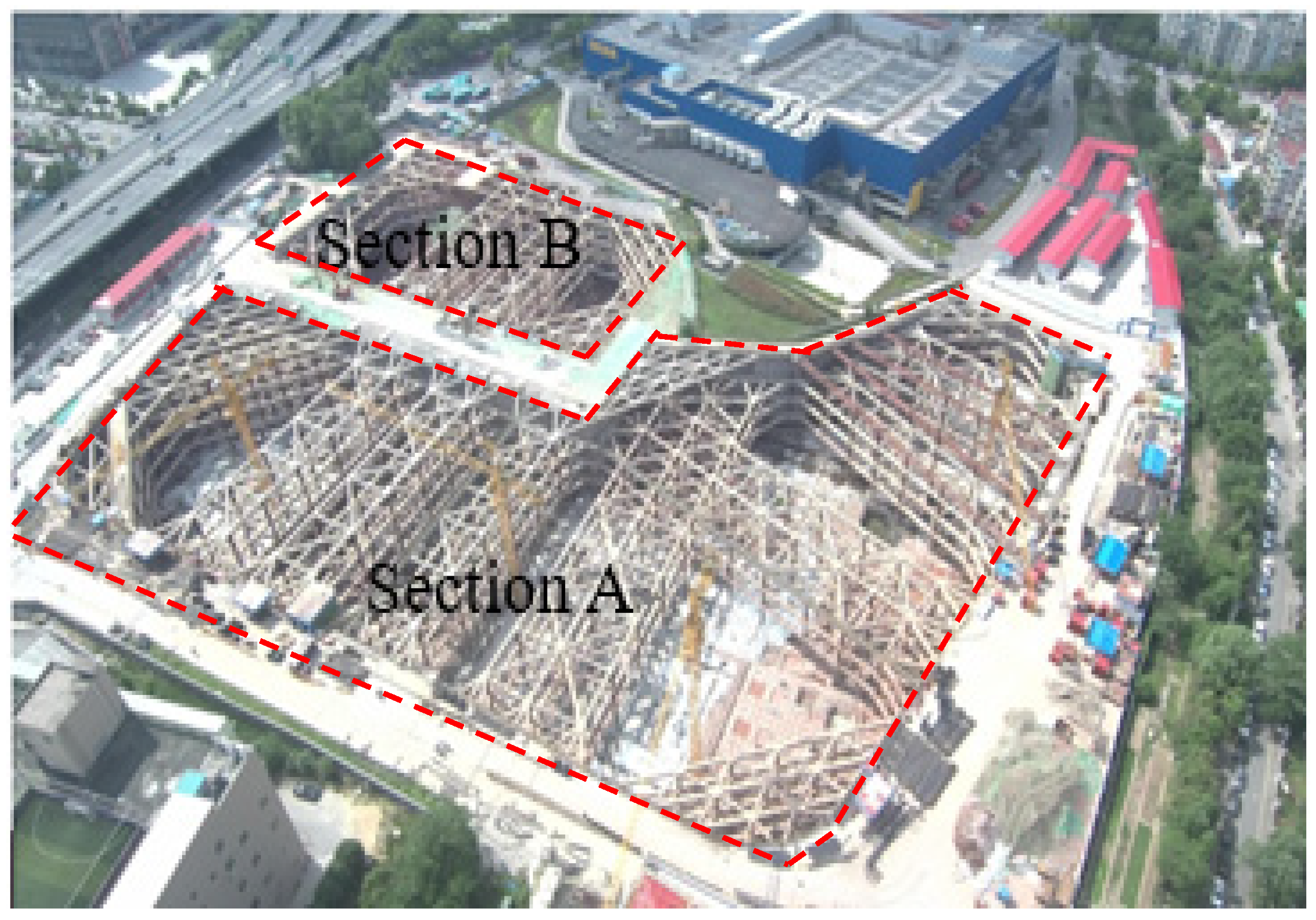
This project is located on the east side of the junction of Kazimen Street and Yuhua East Road in Qinhuai District, Nanjing. The main structure of the project is composed of seven complex buildings with 12–18 floors. There are three-storey (partially four-storey) basements downstairs. The upper structure is to be a frame or frame-core tube structure, the size of the basic column net is 9.0 × 9.0 m, and the foundation is determined to use a raft foundation placed on a natural foundation.
The foundation pit engineering ±0.000 is equivalent to the absolute elevation of 22.5 m. The entire foundation pit is divided into two parts, section A and section B, for excavation, with a total excavation area of about 32,000 m
2. The excavation area of section A of the foundation pit is about 21,300 m
2, the perimeter is about 730 m, and the excavation depth of the foundation pit is 15.25–23.45 m. The excavation area of section B of the foundation pit is about 10,800 m
2, and the excavation depth is 22.15–23.20 m. The regional layout of the foundation pit is shown in
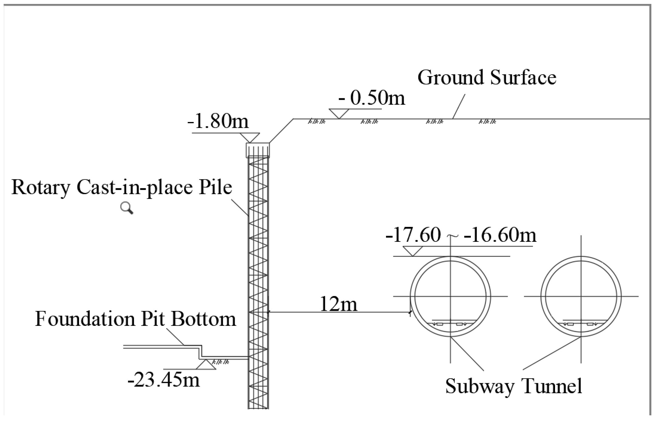
Figure 1. The foundation pit adopts rotary cast-in-place piles with a diameter of 1.1 m and a spacing of 1.3 m as the enclosure structure. The nearby subway in operation is only 12 m away from the rotary cast-in-place piles. A typical cross-sectional schematic diagram of the foundation pit is shown in
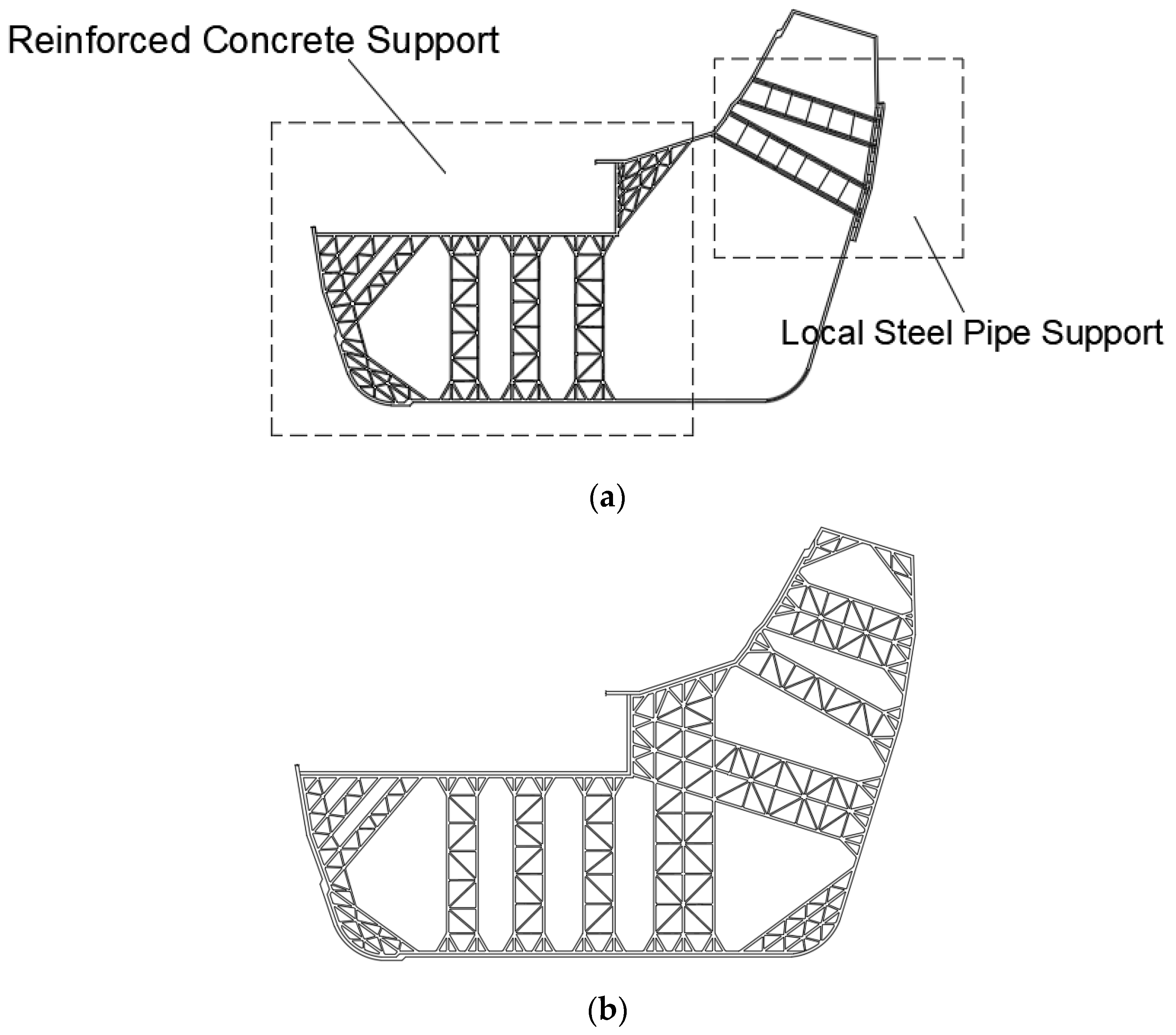
Figure 2. The first floor of the foundation pit section A is partially supported by circular steel pipes, partially by rectangular reinforced concrete, and the lower three floors are all supported by reinforced concrete. The support arrangement in the foundation pit section A is shown in
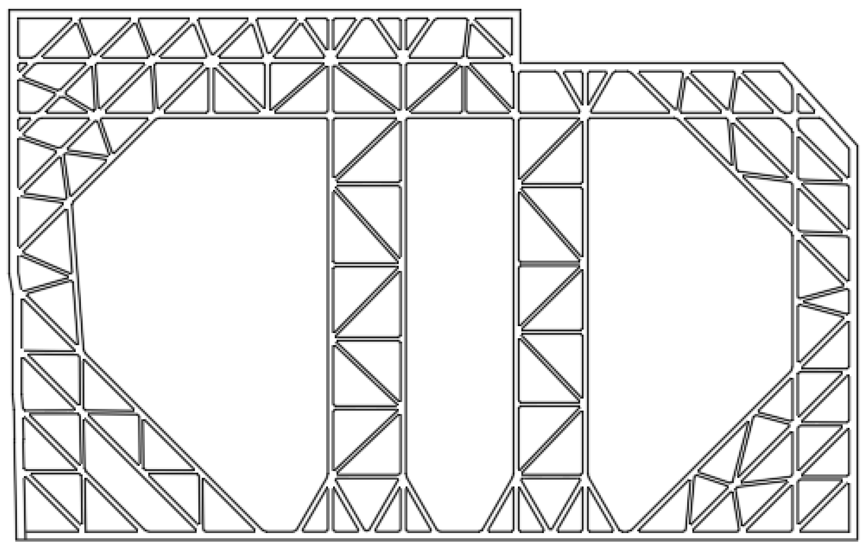
Figure 3. The four-layer rectangular reinforced concrete inner support is used in section B of the foundation pit, and the arrangement of the inner support in section B of the foundation pit is shown in
Figure 4.
The development sequence of the project is to start the foundation pit section A and then section B. There is a time difference in the excavation of the two areas, and the time and space effect is very significant. In order to ensure that the foundation pit section B is affected as little as possible by the excavated foundation pit section A during the construction process, an earth dam is reserved in section B of the foundation pit. After the main structure of the basement on both sides is constructed to ±0.00 m, the backfilling of the third and fourth underground floors with plain concrete is completed, and the permanent retaining wall on the north side is formed, then the excavation construction will be carried out. In the process of support removal, in order to reduce the impact on the surrounding environment, the treatment method of the fertilizer trough around the foundation pit is as follows: the fourth underground floor is backfilled with plain concrete (C15). The fourth and third underground floors on the subway side are backfilled with plain concrete (C15). The rest is backfilled and compacted with good soil.
3. On-Site Monitoring
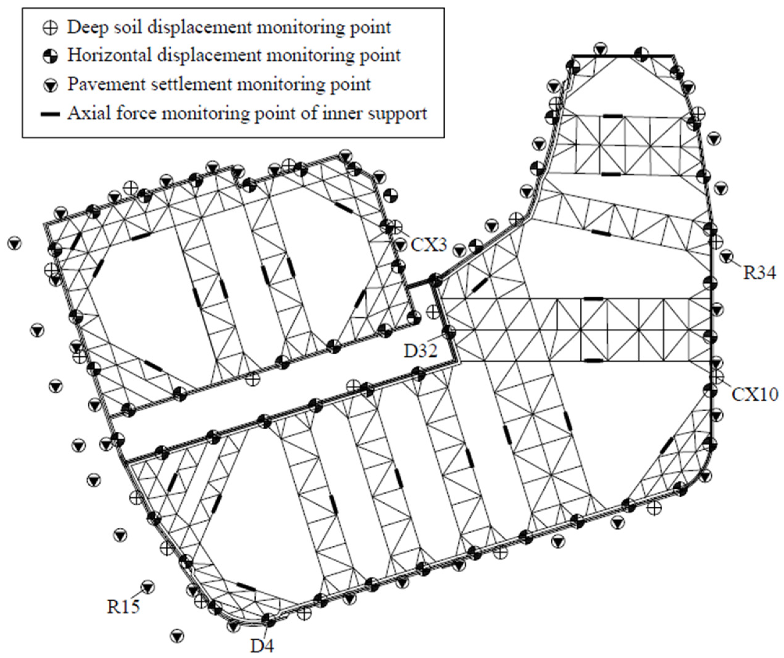
Real-time monitoring of the foundation pit and its surrounding environment is carried out to ensure the safety of foundation pit construction, which consists of conventional foundation pit monitoring and tunnel deformation monitoring. The foundation pit monitoring mainly includes deep soil displacement, pavement settlement around the foundation pit, horizontal displacement of the ring beam, and the axial force of the inner support. The displacement of the deep soil mass is measured by the inclinometer pipe embedded in the supporting pile in advance, and the buried depth of the inclinometer pipe is the same as that of the supporting pile. The settlement of the pavement around the foundation pit and the horizontal displacement of the ring beam are measured through pre-arranged observation points. Considering the existence of tunnels under the western pavement of the foundation pit, the monitoring range of the western pavement of the foundation pit is enlarged. The axial force of the inner support is measured with a rebar gauge. The layout of monitoring points for foundation pit monitoring is shown in
Figure 5. The tunnel deformation monitoring includes horizontal deformation monitoring and vertical deformation monitoring. The specific values will be compared with the finite element simulation results in
Section 4.
There are 44 road settlement monitoring points (R1-R44) laid out on the pavements around the foundation pit. The allowable value of settlement of the surrounding pavements is 20 mm. When the change speed of settlement exceeds 2.5 mm/d, the monitoring system will automatically issue an alarm. The point R34 (east side of the foundation pit) has the largest cumulative settlement, and its value is 14.9 mm. The smallest cumulative settlement occurs in the point R15 (the west side of the foundation pit), and its value is 6.7 mm. From the monitoring results, the foundation pit construction has a slight impact on the surrounding pavements, but the impact is within an acceptable range, and no cracking is observed on the surrounding pavements.
A total of 34 horizontal displacement monitoring points (D1–D34) are arranged on the ring beam of the foundation pit, of which the point D32 has the largest displacement with a value of 9.5 mm, and the point D4 has the smallest displacement with a value of 2.5 mm. The limit allowable value of the horizontal displacement of the ring beam is 20 mm, which is about twice the measured maximum displacement. From the monitoring results, during the removal process of the support, there are two sudden changes in the displacement, which is a normal situation, and all the observed values are within a reasonable range. There are 26 support axial force monitoring points on each layer of the support system. The monitoring results show that most of the support axial force does not exceed 80% of the design value, and only a few parts reach about 90% of the design value, which indicates that there is still a certain safety reserve in the support structure system.
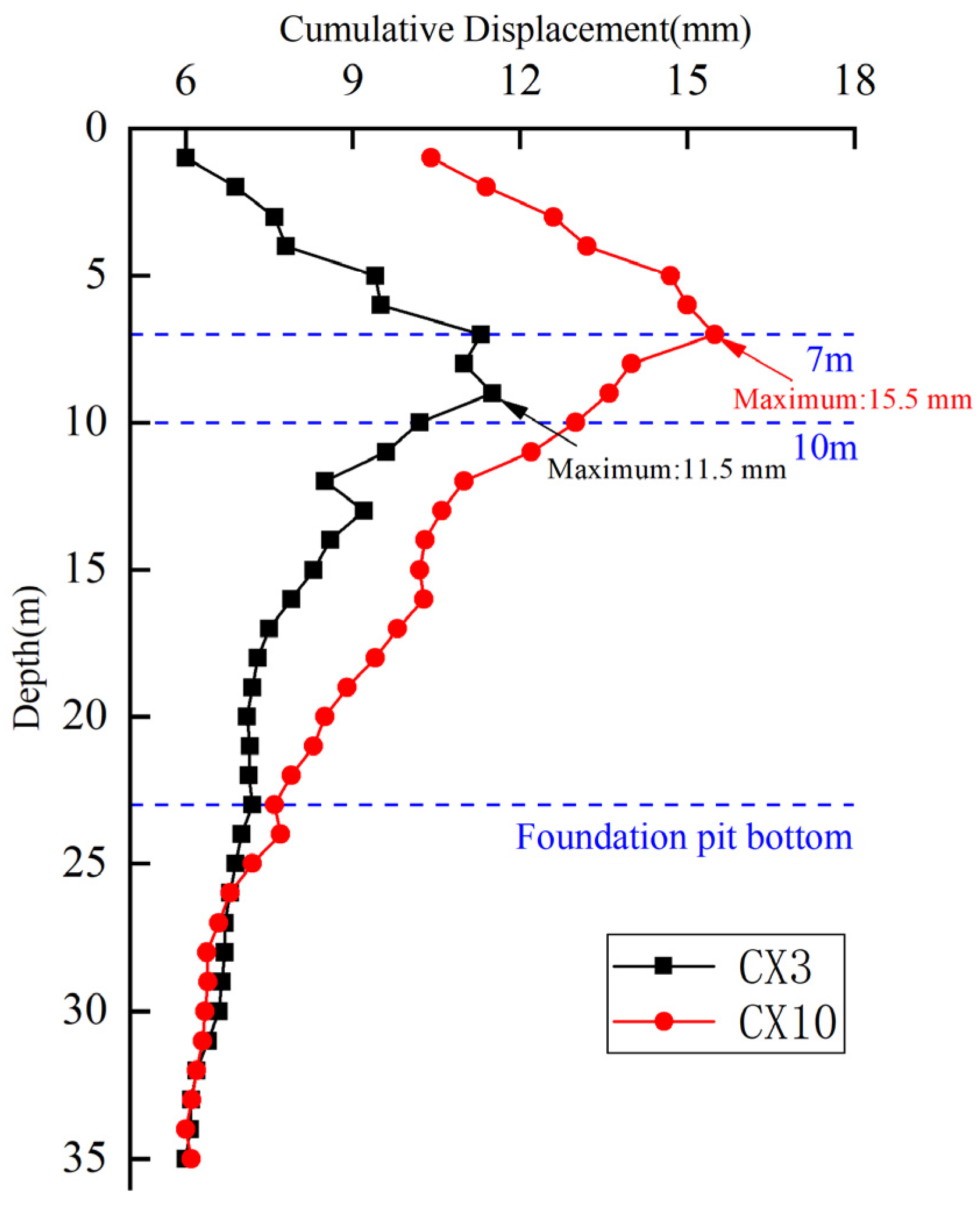
There are 15 monitoring points (CX1–CX15) in the deep soil displacement of the foundation pit, among which the maximum cumulative displacement of each inclination hole is the point CX10, whose value is 15.5 mm, and the minimum cumulative displacement is the point CX3, whose value is 11.5 mm. The limit allowable value of deep soil displacement is 30 mm, and the maximum deformation on site is only close to half of the limit value. The cumulative displacement of monitoring points CX3 and CX10 is shown in
Figure 6. From the monitoring results, the maximum deformation of the inclinometer hole is generally at a depth of 7–10 m, and the observed value is within a reasonable range.
4. Numerical Study
4.1. Model Description
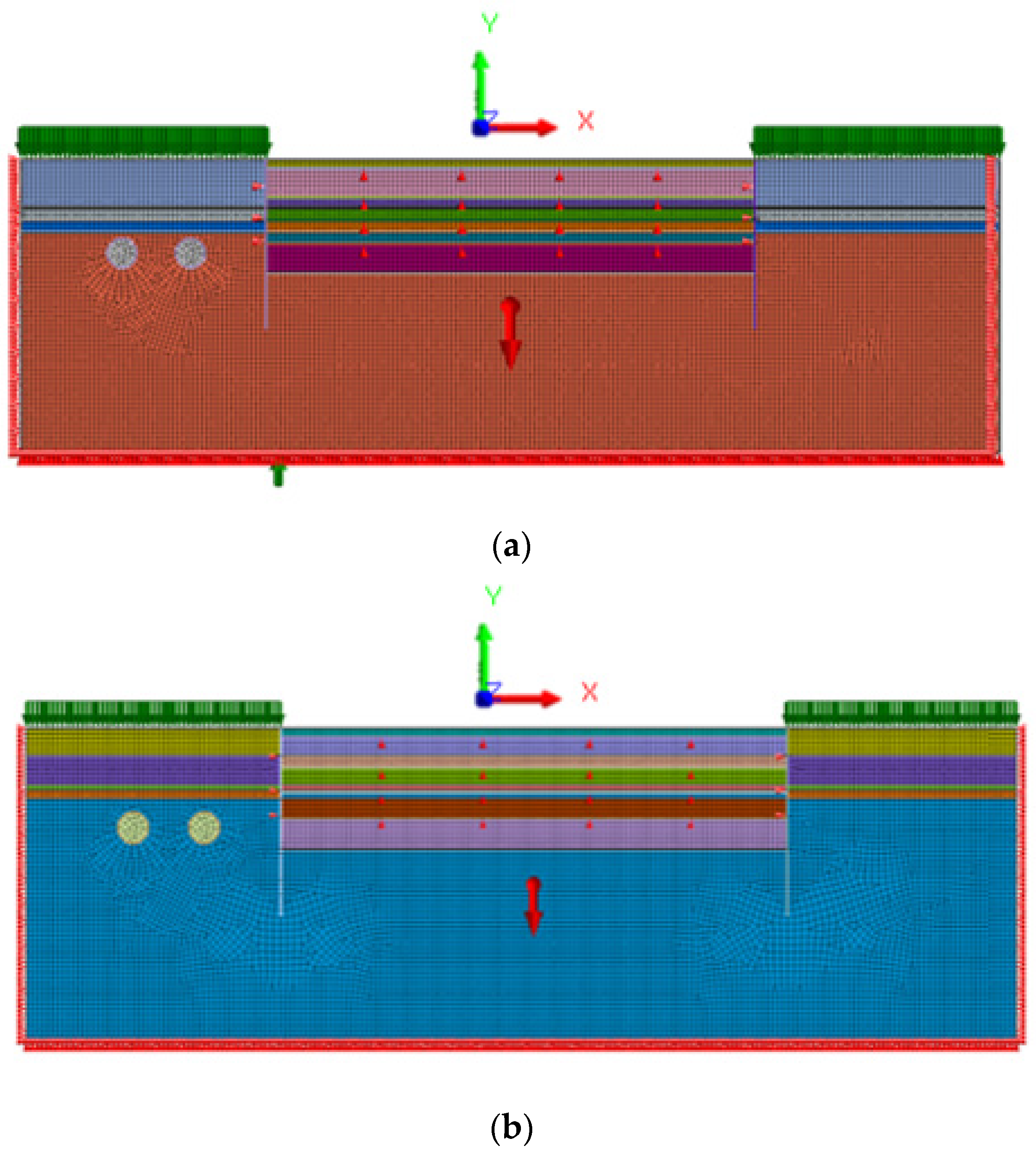
Section A of the foundation pit is supported by reinforced concrete piles and four layers of reinforced concrete inner supports. The first layer is partially supported by steel pipes. The diameter of the supporting pile is 1100 mm, the center distance of the pile is 1300 mm, and the length of the embedded pile below the foundation pit bottom is 11.85 m. According to the actual engineering geological conditions and geometric conditions of the site, a finite element model is established using MIDAS/GTS software. Horizontally, the outer part of the pit extends 50 m from the cast-in-place pile. Vertically, the soil is arranged in layers according to the actual situation, and extends downwards 37 m from the bottom of the pit. The overall size of the model is 200 × 60 m. The model is simulated with planar quadrilateral elements, and the cast-in-place piles, supports and tunnels are simulated with beam elements. The vertical boundary constrains the horizontal displacement, and the lower boundary constrains the displacement in the horizontal and vertical directions. The total number of elements in the model is 13,022 and the number of nodes is 12,733. The meshing diagram of the model is shown in
Figure 7a.
Section B of the foundation pit is supported by reinforced concrete piles and four layers of reinforced concrete inner supports. The diameter of the supporting pile is 1100 mm, the center distance of the pile is 1300 mm, and the length of the embedded pile below the foundation pit bottom is 13.00 m. Similar to the establishment of the numerical model of section A of the foundation pit, for the model of section B, in the horizontal direction, the outer part of the pit extends 50 m from the cast-in-place piles, and in the vertical direction, the soil is arranged in layers according to the actual situation, and extends down from the bottom of the pit for 36 m. The overall size of the model is 200 × 50 m. The total number of elements in the model is 12,255 and the number of nodes is 11,926. It is worth noting that when analyzing the impact of the excavation of the foundation pit in section B on the subway tunnel, it is necessary to consider the impact that the excavation of section A has had on the subway tunnel. The meshing diagram of the model is shown in
Figure 7b.
4.2. Simulation Conditions and Calculation Parameters
In order to better simulate the progress of the actual project, 15 different calculation conditions are set for the numerical simulation of section A and section B of the foundation pit, and all the calculation conditions are shown in
Table 1. In the first step, the soil reaches equilibrium under its own weight. The second step simulates the construction of the foundation pit support structure, activating part of the concrete lining of the tunnel and freezing the soil inside the tunnel. The next thirteen steps are used to simulate and calculate according to the actual construction process of the project. When the simulated excavation reaches the corresponding elevation, the soil above the corresponding elevation inside the foundation pit is frozen. When simulating construction or removal of the concrete inner supports, activate or freeze the concrete inner supports in the finite element model accordingly.
The constitutive model of the soil element adopts the Mohr–Coulomb constitutive model, and the relevant model parameters of the Mohr–Coulomb model refer to the data of the field geotechnical test of the project. The linear elastic model is used for the rotary cast-in-place piles, the concrete inner support, and the concrete lining of the tunnel. The specific physical and mechanical parameters of soil and concrete are shown in
Table 2 and
Table 3.
4.3. Analysis of Vertical Deformation of Subway Tunnel
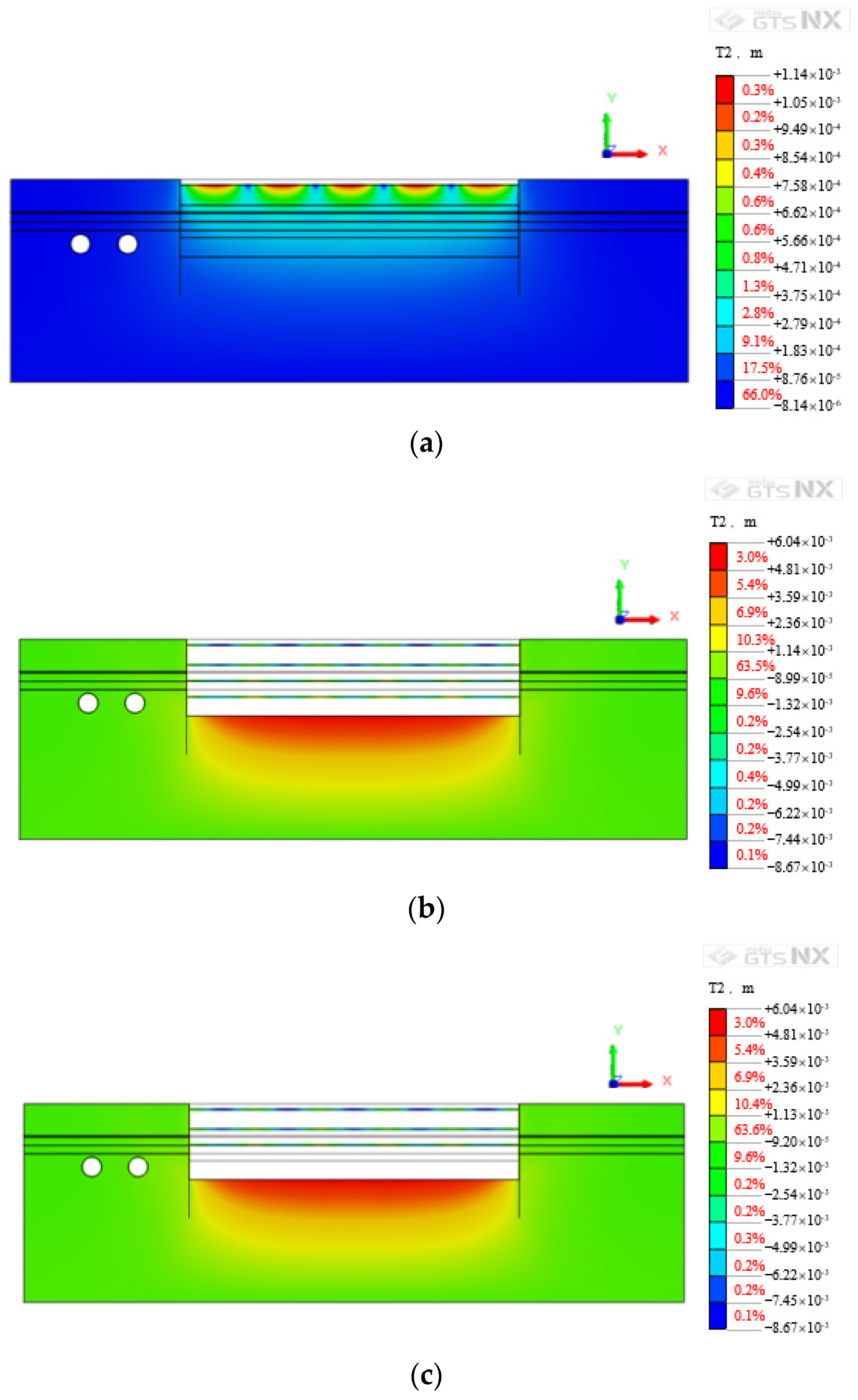
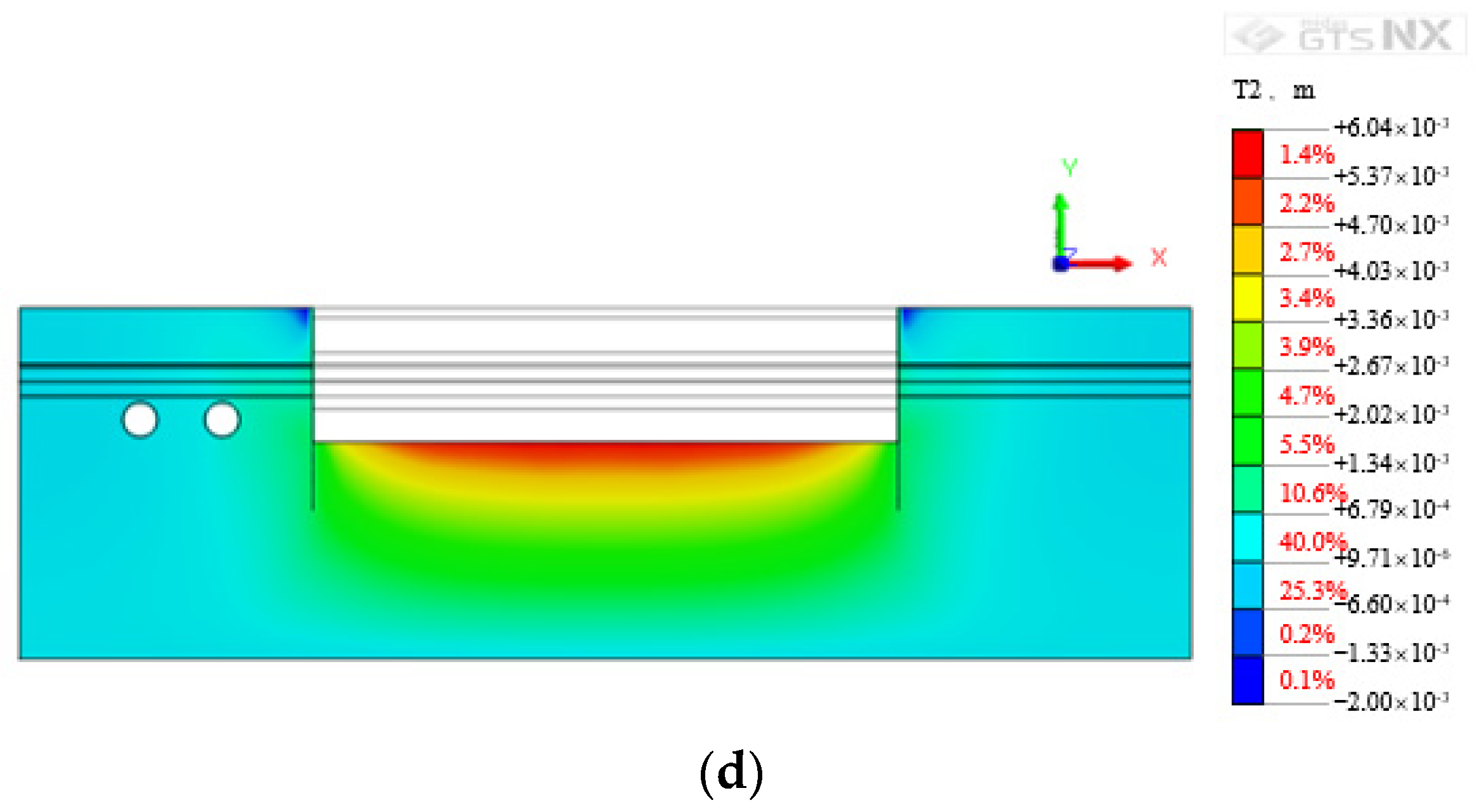
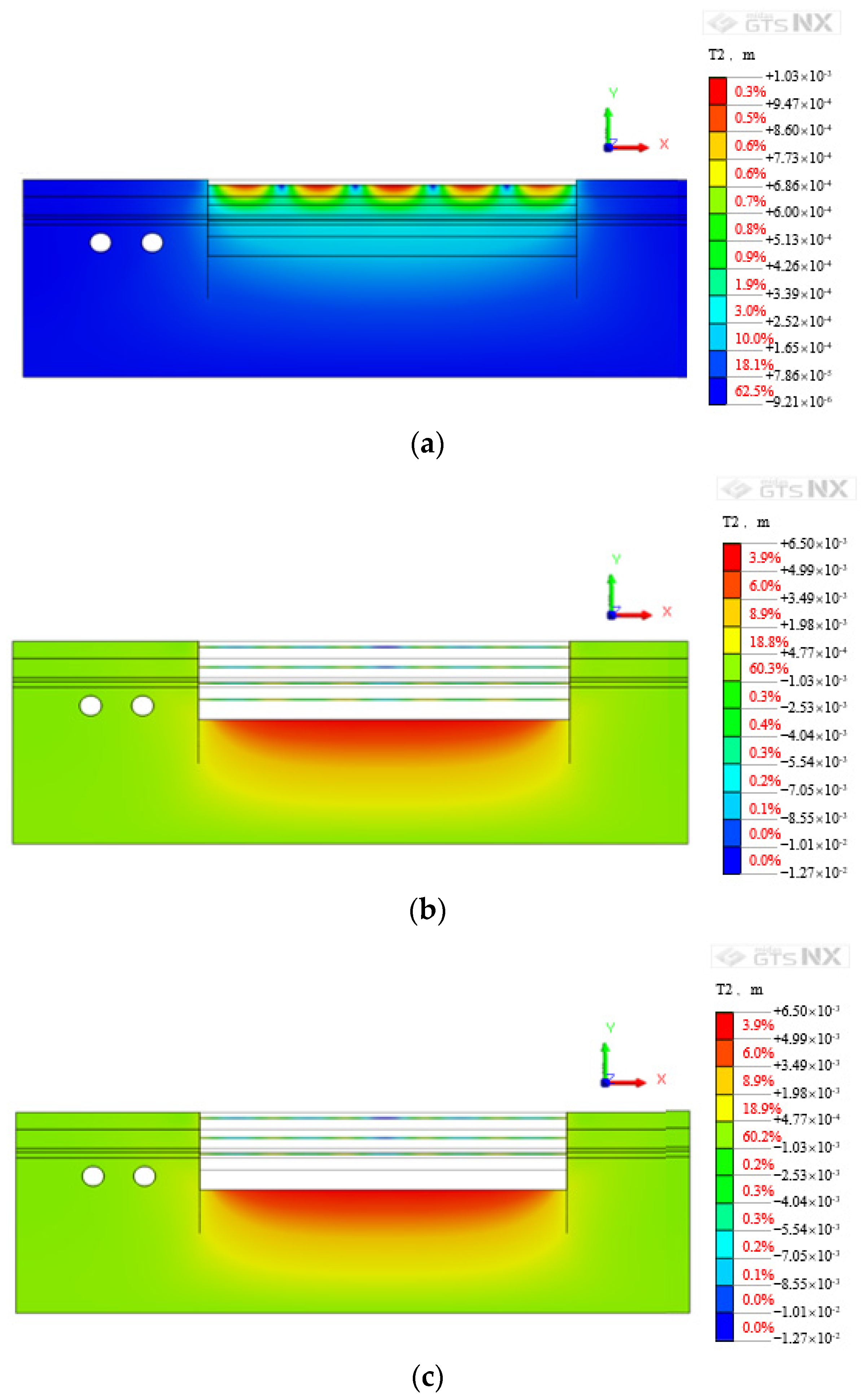
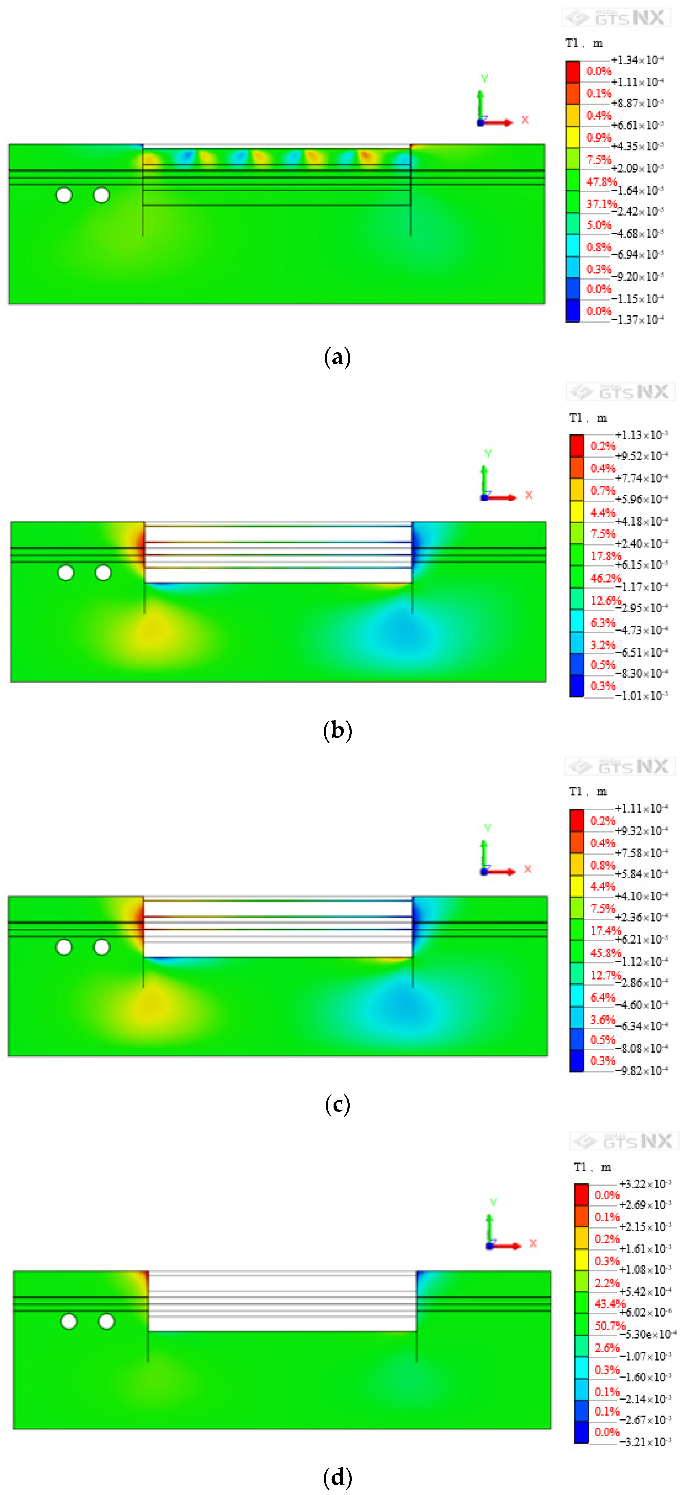
Figure 8 is a cloud map of the vertical deformation of the subway tunnel caused by the excavation of section A of the foundation pit under some working conditions. According to the simulation results of finite element software, as the excavation depth increases, the maximum vertical deformation of the subway tunnel increases continuously. When excavating to the design elevation at the bottom of the foundation pit, the vertical deformation of the subway tunnel reaches 1.32 mm. With the removal of the reinforced concrete inner support of the foundation pit, the vertical deformation of the subway tunnel is further increased. When all the inner supports are removed, the vertical deformation has reached 2.45 mm.
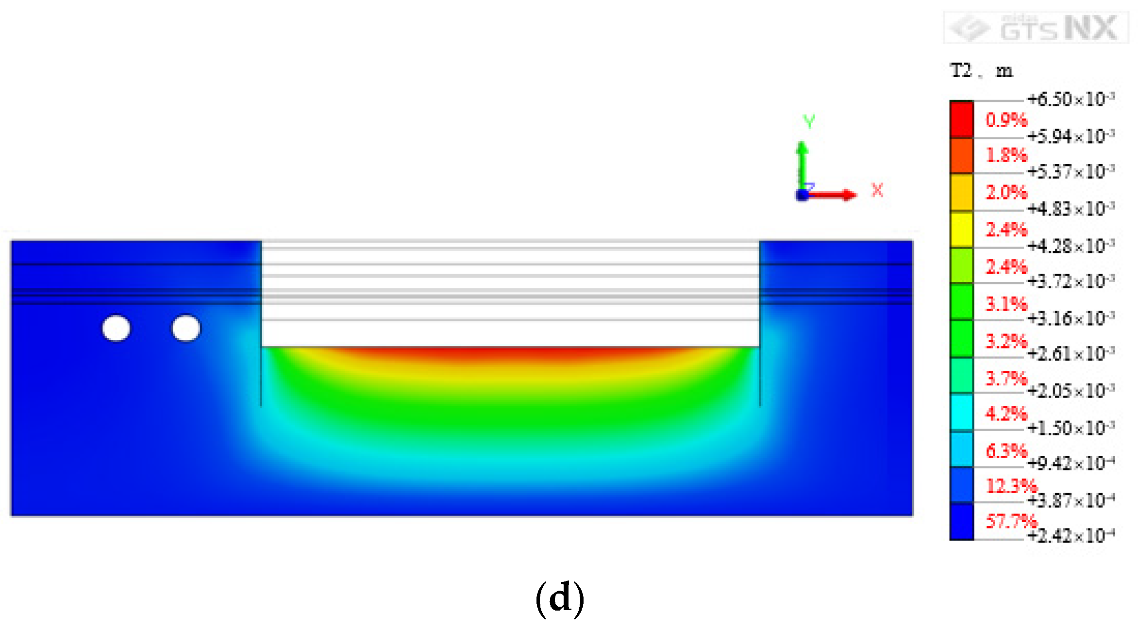
Figure 9 is a cloud map of the vertical deformation of the subway tunnel caused by the excavation of section B of the foundation pit under some working conditions. The vertical deformation of the subway tunnel caused by the excavation of the foundation pit section B and the removal of the inner support is similar to the construction of section A, which leads to an increase in the vertical deformation of the subway tunnel. The vertical deformation of the subway tunnel corresponds to the excavation of the foundation pit section B to the design elevation and the removal of the first layer inner support is 1.61 and 2.61 mm, respectively.
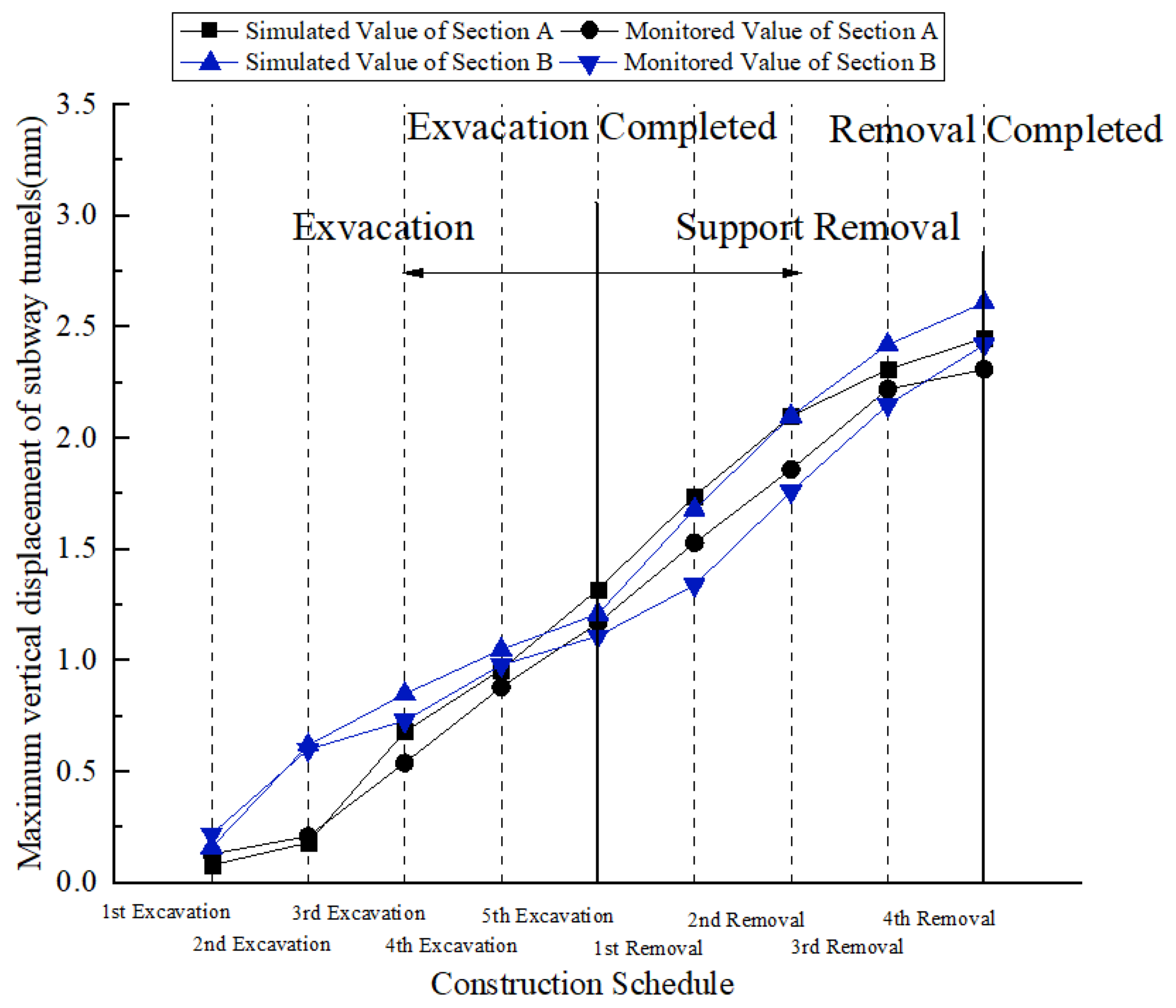
The maximum vertical deformation of the subway tunnel caused by the construction of the foundation pit section A and the foundation pit section B is recorded in
Table 4. The calculation results of finite element software show that in the first four excavations, the vertical deformation of the subway tunnel caused by section B of the foundation pit is greater than that of section A. However, when all the foundation pit is excavated, the vertical deformation of the subway tunnel caused by section B of the foundation pit is smaller than that of section A. When the fourth layer supports are removed, the vertical deformation of the subway tunnel caused by section A is larger than that of section B. However, when all the supports are removed, the vertical deformation of the subway tunnel caused by section A is smaller than that of section B. The data in
Table 4 are plotted as a line graph and recorded in
Figure 10. It can be seen from
Figure 10 that the variation trend of the simulated value of the maximum vertical deformation caused by the construction of section A and section B is basically consistent with the monitored value. The largest relative error in the construction process of the foundation pit in section A appears in the first excavation condition, and its value is 38.5%. The largest relative error during the construction of the foundation pit in section B also appears in the first excavation condition, and its value is 27.2%. The relative error of the numerical simulation is large, which is mainly caused by the small value of the maximum vertical deformation of the subway tunnel itself. According to the code requirements of the area where the project is located, the absolute settlement of subway structural facilities should be less than or equal to 10 mm. The maximum vertical deformation of the actual subway tunnel caused by the construction of the foundation pit in section A and the foundation pit in section B is 2.31 and 2.42 mm, which are far less than the specification limit.
4.4. Analysis of Horizontal Deformation of Subway Tunnel
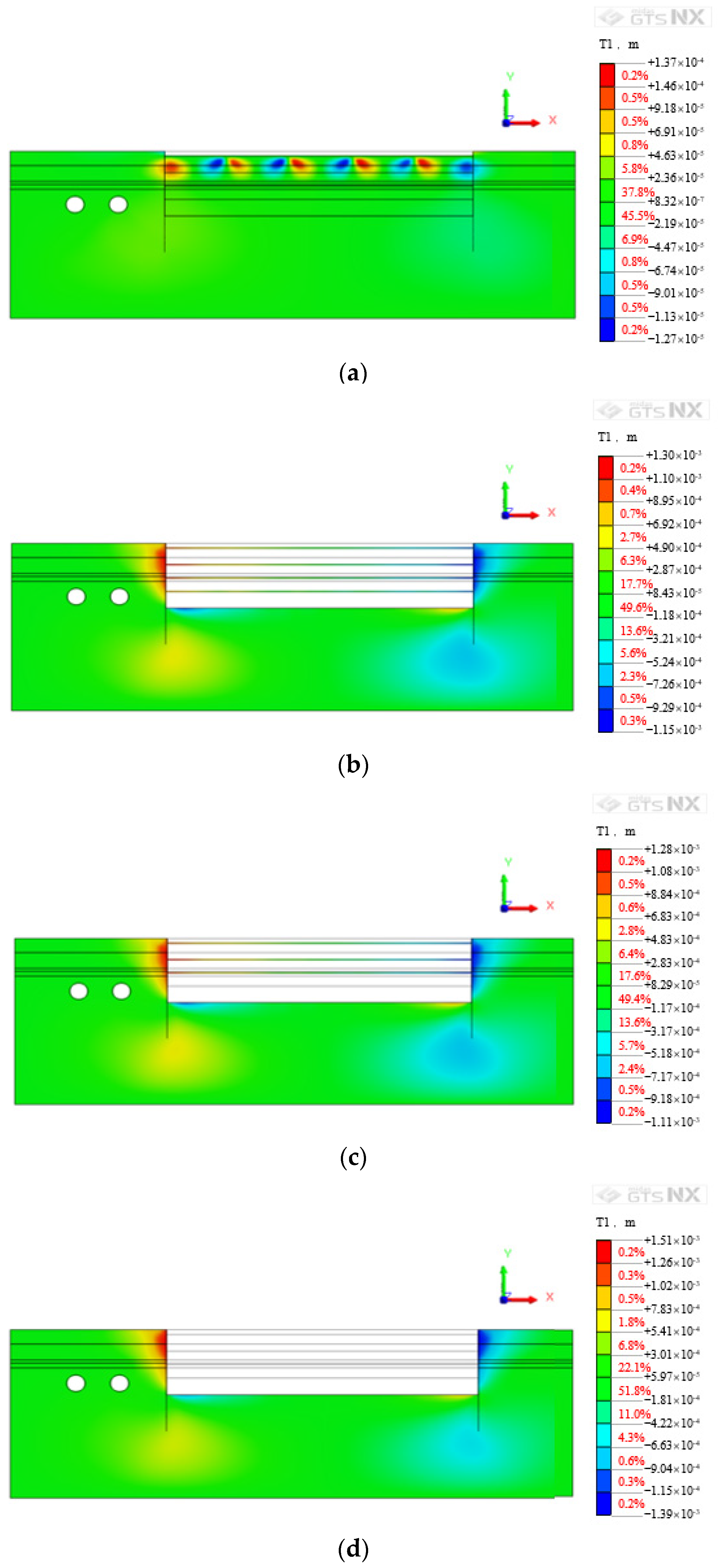
Figure 11 is a cloud map of the horizontal deformation of the subway tunnel caused by the excavation of section A of the foundation pit under some working conditions. According to the simulation results of finite element software, as the excavation depth increases, the maximum horizontal deformation of the subway tunnel increases continuously. When excavating to the design elevation at the bottom of the foundation pit, the horizontal deformation of the subway tunnel reached 0.30 mm. With the removal of the reinforced concrete inner support of the foundation pit, the horizontal deformation of the subway tunnel has further increased. When all the inner supports are removed, the horizontal deformation has reached 0.49 mm.
Figure 12 is a cloud map of the horizontal deformation of the subway tunnel caused by the excavation of section B of the foundation pit under some working conditions. The horizontal deformation trend of the subway tunnel caused by the excavation and the removal of the inner support in section B is similar to the construction of section A, which leads to an increase in the horizontal deformation of the subway tunnel. The horizontal deformation of the subway tunnel corresponds to the excavation of the foundation pit in section B, to the design elevation, and the removal of the first layer inner support is 0.42 and 0.62 mm, respectively.
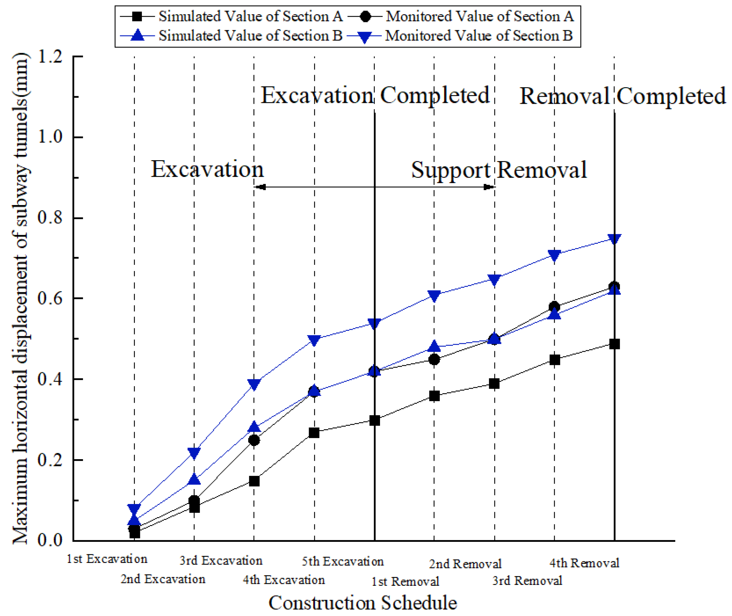
The maximum horizontal deformation of the subway tunnel caused by the construction of the foundation pit in section A and the foundation pit in section B is recorded in
Table 5. In general, the horizontal deformation of the subway tunnel is smaller than the vertical displacement. The data in
Table 5 are plotted as a line graph and recorded in
Figure 13. It can be seen from
Figure 13 that the variation trend of the simulated value of the maximum horizontal deformation caused by the construction in section A and section B is basically consistent with the monitored value. The monitoring value of the maximum horizontal deformation of the tunnel caused by the foundation pit construction is greater than the numerical simulation value, and the maximum horizontal deformation of the subway tunnel caused by the construction of the foundation pit section A is smaller than that of section B. The largest relative error in the construction process of the foundation pit section A appears in the first excavation condition, and its value is 33%. The largest relative error during the construction of the foundation pit section B also appears in the first excavation condition, and its value is 37.5%. The relative error of the numerical simulation is large, which is mainly caused by the small value of the maximum horizontal deformation of the subway tunnel itself. According to the code requirements of the area where the project is located, the horizontal displacement of subway structural facilities should be less than or equal to 10 mm. The maximum horizontal deformation of the actual subway tunnel caused by the construction of the foundation pit in section A and the foundation pit in section B is 0.49 and 0.62 mm, which are far less than the specification limit.
5. Conclusions
This paper describes a foundation pit project adjacent to a subway tunnel. The foundation pit has a complex geometry, deep excavation depth and large excavation area, and has very high requirements for support systems to resist deformation. Due to the development cycle, demolition and other reasons, the entire foundation pit is excavated in two sections, A and B, and the time and space effect of the excavation is significant. There are subway lines in operation within 12 m west of the basement exterior wall on the west side of the foundation pit, and the tunnel burial depth is less than the excavation depth of the foundation pit. In order to explore the influence of foundation pit excavation on the adjacent subway, MIDAS/GTS software is used to establish a finite element model for the excavation of section A and section B, and the rationality of the finite element results is verified by monitoring the tunnel. Based on the above discussion, the following conclusions are finally drawn:
The enclosure structure of the foundation pit adopts rotary cast-in-place piles, and the support system adopts four-layer (local three-layer) reinforced concrete rectangular inner support. According to the monitoring results, this foundation pit support system can well limit the settlement around the road, the horizontal displacement of the ring beam, and the deep soil displacement of the foundation pit. At the same time, the axial force of the inner support is always maintained at a relatively safe level. Compared with the underground diaphragm wall, the support system saves 20 million yuan in project cost and about 3 months in the construction period while meeting the deformation requirements;
According to the finite element calculation results, the horizontal displacement of the subway tunnel is generally smaller than the vertical displacement. Therefore, vertical deformation should be the focus of tunnel deformation monitoring. The maximum vertical displacement of the subway tunnel caused by the excavation of the foundation pit in section A and section B is 2.45 and 2.61 mm, and the maximum horizontal displacement of the subway tunnel caused by the excavation of the foundation pit in section A and section B is 0.49 and 0.62 mm. The maximum vertical displacement and horizontal displacement are both less than the specification limit value of 10 mm. The excavation of the foundation pit of this project has little impact on the subway structure and facilities, and the normal operation of the subway facilities is effectively guaranteed. There is no need for additional reinforcement and protection of the subway tunnel. When evaluating the impact of foundation pit excavation on the surrounding environment, the finite element calculation results can be compared with on-site monitoring data to verify the accuracy of the finite element model; and
Future research can consider the influence of foundation pit drainage, geological conditions, subway tunnel type, and other factors on tunnel deformation. Furthermore, future research can attempt to apply emerging monitoring techniques to foundation pit monitoring, such as the Probabilistic Power Spectral Density (PPSD) method, to assist in the assessment of the impact of foundation pit excavation on the surrounding environment.
Author Contributions
Conceptualization, G.D. and Z.L.; methodology, H.W.; validation, G.D.; formal analysis, H.W. and Z.Y.; investigation, X.Z.; resources, X.Z.; data curation, S.C. and J.Z.; writing—original draft preparation, Z.L.; writing—review and editing, G.D.; project administration, X.Z. All authors have read and agreed to the published version of the manuscript.
Funding
This research was funded by the Science and Technology Research and Development Project of CSCEC (CSCEC-2020-Z-21) and the National Natural Science Foundation of China (NSFC Grant No.s 52078128, 51878160).
Institutional Review Board Statement
Not applicable.
Informed Consent Statement
Not applicable.
Data Availability Statement
Dataare contained within the article.
Conflicts of Interest
The authors declare no conflict of interest.
References
- Liu, B.; Fan, X.H.; Wang, Y.Y.; Zhang, J.B.; Fan, Z.B. Influences of Excavation on Adjacent Existing Metro Tunnels: A Review. Chin. J. Geotech. Eng. 2021, 43, 253–258. (In Chinese) [Google Scholar]
- Wang, F.C.; Chen, J.X.; Wen, Y.Z. Risk Analysis of a Railway Station in Shenyang with Cover Excavation and Top-Down Method. In Proceedings of the 6th International Conference on Environmental Science and Civil Engineering, Nanchang, China, 4–5 January 2020; Volume 455. [Google Scholar]
- Zhang, Z.; Huang, M.; Wang, W. Evaluation of deformation response for adjacent tunnels due to soil unloading in excavation engineering. Tunn. Undergr. Space Technol. 2013, 38, 244–253. [Google Scholar] [CrossRef]
- Zhang, Z.; Zhang, M.; Zhao, Q. A simplified analysis for deformation behavior of buried pipelines considering disturbance effects of underground excavation in soft clays. Arab. J. Geosci. 2015, 8, 7771–7785. [Google Scholar] [CrossRef]
- Zhang, J.F.; Chen, J.J.; Wang, J.H.; Zhu, Y.F. Prediction of Tunnel Displacement Induced by Adjacent Excavation in Soft Soil. Tunn. Undergr. Space Technol. Inc. Trenchless Technol. Res. 2013, 36, 24–33. [Google Scholar] [CrossRef]
- Liang, R.; Xia, T.; Huang, M.; Lin, C. Simplified analytical method for evaluating the effects of adjacent excavation on shield tunnel considering the shearing effect. Comput. Geotech. 2016, 81, 167–187. [Google Scholar] [CrossRef]
- Zhang, D.-M.; Huang, Z.-K.; Li, Z.-L.; Zong, X. Analytical solution for the response of an existing tunnel to a new tunnel excavation underneath. Comput. Geotech. 2019, 108, 197–211. [Google Scholar] [CrossRef]
- Marta, D. Tunnel Complex Unloaded by a Deep Excavation. Comput. Geotech. 2001, 28, 469–493. [Google Scholar]
- Sharma, J.; Hefny, A.; Zhao, J.; Chan, C. Effect of large excavation on deformation of adjacent MRT tunnels. Tunn. Undergr. Space Technol. 2001, 16, 93–98. [Google Scholar] [CrossRef]
- Hu, Z.F.; Yue, Z.Q.; Zhou, J.; Tham, L.G. Design and construction of a deep excavation in soft soils adjacent to the Shanghai Metro tunnels. Can. Geotech. J. 2003, 40, 933–948. [Google Scholar] [CrossRef] [Green Version]
- Lian, G.L. Research on the Influence of Foundation Pit Excavation on the Deformation of the Existing Shield Tunnel. Master’s Thesis, South China University of Technology, Guangzhou, China, 2014. (In Chinese). [Google Scholar]
- Huo, Z.; Yan, S.; Zhang, Q. Numerical Analysis of the Influence of Foundation Pit Unloading and Excavation on the Underground Subway Tunnel. J. Shandong Univ. Sci. Technol. (Nat. Sci.) 2016, 35, 62–67. (In Chinese) [Google Scholar]
- Shi, J.; Ng, C.W.W.; Chen, Y. Three-dimensional numerical parametric study of the influence of basement excavation on existing tunnel. Comput. Geotech. 2015, 63, 146–158. [Google Scholar] [CrossRef]
- Shi, J.; Ng, C.W.; Chen, Y. A simplified method to estimate three-dimensional tunnel responses to basement excavation. Tunn. Undergr. Space Technol. 2017, 62, 53–63. [Google Scholar] [CrossRef]
- Li, M.G.; Chen, J.J.; Wang, J.H.; Zhu, Y.F. Comparative Study of Construction Methods for Deep Excavations above Shield Tunnels. Tunn. Undergr. Space Technol. Inc. Trenchless Technol. Res. 2018, 71, 329–339. [Google Scholar] [CrossRef]
- Huang, X.; Schweiger, H.F.; Huang, H.-W. Influence of Deep Excavations on Nearby Existing Tunnels. Int. J. Géoméch. 2013, 13, 170–180. [Google Scholar] [CrossRef]
- Burford, D. Heave of tunnels beneath the Shell Center. Geotechnique 1988, 38, 135–137. [Google Scholar] [CrossRef]
- Simpson, B.; Vardanega, P.J. Results of Monitoring at the British Library Excavation. Proc. Inst. Civ. Eng.-Geotech. Eng. 2014, 167, 99–116. [Google Scholar] [CrossRef] [Green Version]
- Zhang, L.M.; Zhu, G.P.; Zheng, X.Y.; Yang, Z.D. Monitoring and Analysis of Influence of Excavations on Adjacent Metro Structures in Soft Soils. Chin. J. Geotech. Eng. 2017, 39, 175–179. (In Chinese) [Google Scholar]
- Zhang, H.-B.; Chen, J.-J.; Fan, F.; Wang, J.-H. Deformation Monitoring and Performance Analysis on the Shield Tunnel Influenced by Adjacent Deep Excavations. J. Aerosp. Eng. 2017, 30, B4015002. [Google Scholar] [CrossRef]
- Sui, H.B.; Shi, B.; Zhang, D. Distributed Optical Fiber Sensor-based Monitoring for Foundation Pit Engineering. J. Disaster Prev. Mitig. Eng. 2008, 28, 184–191. [Google Scholar]
- Tang, C.; Hou, H.; Fan, T.; Zhao, L.; Wang, Y.; Li, Z.; Wang, X. Studies on automatic extraction of precise 3D laser measurement data in specific section of subway tunnel. Proc. SPIE 2020, 11562, 1156212. [Google Scholar] [CrossRef]
Figure 1.
Layout plan of foundation pit section.
Figure 1.
Layout plan of foundation pit section.
Figure 2.
Schematic diagram of the typical cross-section of foundation pit.
Figure 2.
Schematic diagram of the typical cross-section of foundation pit.
Figure 3.
Support layout in section A of the foundation pit. (a) Layout of inner support on the first layer; (b) Layout of 2nd, 3rd and 4th layer inner support.
Figure 3.
Support layout in section A of the foundation pit. (a) Layout of inner support on the first layer; (b) Layout of 2nd, 3rd and 4th layer inner support.
Figure 4.
Support layout in section B of the foundation pit.
Figure 4.
Support layout in section B of the foundation pit.
Figure 5.
Monitoring point layout.
Figure 5.
Monitoring point layout.
Figure 6.
Deep soil displacement curve in CX3 and CX10.
Figure 6.
Deep soil displacement curve in CX3 and CX10.
Figure 7.
Meshing diagram of finite element model. (a) Finite element model of section A of the foundation pit. (b) Finite element model of section B of the foundation pit.
Figure 7.
Meshing diagram of finite element model. (a) Finite element model of section A of the foundation pit. (b) Finite element model of section B of the foundation pit.
Figure 8.
Vertical deformation caused by construction of section A. (a) Excavate to −2.20 m elevation. (b) Excavate to the design elevation of the bottom of the foundation pit. (c) The inner supports on the fourth layer are removed. (d) All inner supports are removed.
Figure 8.
Vertical deformation caused by construction of section A. (a) Excavate to −2.20 m elevation. (b) Excavate to the design elevation of the bottom of the foundation pit. (c) The inner supports on the fourth layer are removed. (d) All inner supports are removed.
Figure 9.
Vertical deformation caused by construction of section B. (a) Excavate to −2.20 m elevation. (b) Excavate to the design elevation of the bottom of the foundation pit. (c) The inner supports on the fourth layer are removed. (d) All inner supports are removed.
Figure 9.
Vertical deformation caused by construction of section B. (a) Excavate to −2.20 m elevation. (b) Excavate to the design elevation of the bottom of the foundation pit. (c) The inner supports on the fourth layer are removed. (d) All inner supports are removed.
Figure 10.
Maximum vertical deformation of subway tunnel caused by foundation pit construction.
Figure 10.
Maximum vertical deformation of subway tunnel caused by foundation pit construction.
Figure 11.
Horizontal deformation subway tunnel caused by construction of section A. (a) Excavate to −2.20 m elevation. (b) Excavate to the design elevation of the bottom of the foundation pit. (c) The inner supports on the fourth layer are removed. (d) All inner supports are removed.
Figure 11.
Horizontal deformation subway tunnel caused by construction of section A. (a) Excavate to −2.20 m elevation. (b) Excavate to the design elevation of the bottom of the foundation pit. (c) The inner supports on the fourth layer are removed. (d) All inner supports are removed.
Figure 12.
Horizontal deformation subway tunnel caused by construction of section B.(a) Excavate to −2.20 m elevation. (b) Excavate to the design elevation of the bottom of the foundation pit. (c) The inner supports on the fourth layer are removed. (d) All inner supports are removed.
Figure 12.
Horizontal deformation subway tunnel caused by construction of section B.(a) Excavate to −2.20 m elevation. (b) Excavate to the design elevation of the bottom of the foundation pit. (c) The inner supports on the fourth layer are removed. (d) All inner supports are removed.
Figure 13.
Maximum horizontal deformation of subway tunnel caused by foundation pit construction.
Figure 13.
Maximum horizontal deformation of subway tunnel caused by foundation pit construction.
Table 1.
Simulation conditions of finite element model.
Table 1.
Simulation conditions of finite element model.
| | Simulation Conditions |
|---|
| Step0 | Simulate the stress field of soil under its own weight, activate overload and boundary conditions |
| Step1 | Construct cast-in-place piles, and activate tunnels elements |
| Step2 | Excavation to elevation −2.20 |
| Step3 | Construct the first layer of supports |
| Step4 | Excavation to elevation −8.15 |
| Step5 | Construct the second layer of supports |
| Step6 | Excavation to elevation −12.95 |
| Step7 | Construct the third layer of supports |
| Step8 | Excavation to elevation −17.75 |
| Step9 | Construct the fourth layer of supports |
| Step10 | Excavation to the design elevation of the bottom of the foundation pit |
| Step11 | Remove the fourth layer of support |
| Step12 | Remove the third layer of support |
| Step13 | Remove the second layer of support |
| Step14 | Remove the first layer of support |
Table 2.
Soil physical and mechanical parameters of finite element model.
Table 2.
Soil physical and mechanical parameters of finite element model.
| Name | γ
(kN/m3) | E
(MPa) | ν | c
(kPa) | φ
(°) |
|---|
| Fill | 19.4 | 2.00 | 0.35 | 10.0 | 15.0 |
| Silty clay | 19.7 | 3.00 | 0.25 | 77.9 | 19.2 |
| Silty clay mixed pebbles | 19.8 | 3.00 | 0.25 | 40.0 | 18.0 |
| Fully weathered argillaceous sandstone | 19.7 | 3.90 | 0.25 | 57.8 | 18.8 |
| Strongly weathered argillaceous sandstone | 23.4 | 4.50 | 0.25 | 60.0 | 19.0 |
| Moderately weathered argillaceous sandstone | 23.8 | 5.00 | 0.20 | 110.0 | 25.0 |
| Fill | 19.4 | 2.00 | 0.35 | 10.0 | 15.0 |
Table 3.
Physical and mechanical parameters of concrete members in finite element model.
Table 3.
Physical and mechanical parameters of concrete members in finite element model.
| Name | γ
(kN/m3) | E
(MPa) | ν | h (m) | b (m) |
|---|
| Rotary cast-in-place piles | 25.0 | 30.0 | 0.20 | 1.1 |
| First layer concrete support | 25.0 | 30.0 | 0.20 | 0.70 | 0.60 |
| Second layer concrete support | 25.0 | 30.0 | 0.20 | 0.80 | 0.70 |
| Third layer concrete support | 25.0 | 30.0 | 0.20 | 0.85 | 0.75 |
| Fourth layer concrete support | 25.0 | 30.0 | 0.20 | 0.85 | 0.8 |
| Concrete lining | 25.0 | 30.0 | 0.20 | | |
Table 4.
Maximum vertical deformation of subway tunnel caused by pit construction.
Table 4.
Maximum vertical deformation of subway tunnel caused by pit construction.
| Simulation Conditions | Simulation Value Caused by Section A (mm) | Monitoring Value Caused by Section A (mm) | Simulation Value Caused by Section B (mm) | Monitoring Value Caused by Section B (mm) |
|---|
| Excavation to elevation −2.20 | 0.08 | 0.13 | 0.16 | 0.22 |
| Excavation to elevation −8.15 | 0.18 | 0.21 | 0.62 | 0.6 |
| Excavation to elevation −12.95 | 0.68 | 0.54 | 0.85 | 0.73 |
| Excavation to elevation −17.75 | 0.96 | 0.88 | 1.05 | 0.98 |
| Excavation to the design elevation of the bottom of the foundation pit | 1.32 | 1.17 | 1.21 | 1.11 |
| Remove the fourth layer of support | 1.74 | 1.53 | 1.68 | 1.34 |
| Remove the third layer of support | 2.10 | 1.86 | 2.10 | 1.76 |
| Remove the second layer of support | 2.31 | 2.22 | 2.42 | 2.15 |
| Remove the first layer of support | 2.45 | 2.31 | 2.61 | 2.42 |
Table 5.
Maximum horizontal deformation of subway tunnel caused by pit construction.
Table 5.
Maximum horizontal deformation of subway tunnel caused by pit construction.
| Simulation Conditions | Simulation Value Caused by Section A (mm) | Monitoring Value Caused by Section A (mm) | Simulation Value Caused by Section B (mm) | Monitoring Value Caused by Section B (mm) |
|---|
| Excavation to elevation −2.20 | 0.02 | 0.03 | 0.05 | 0.08 |
| Excavation to elevation −8.15 | 0.085 | 0.1 | 0.15 | 0.22 |
| Excavation to elevation −12.95 | 0.15 | 0.25 | 0.28 | 0.39 |
| Excavation to elevation −17.75 | 0.27 | 0.37 | 0.37 | 0.5 |
| Excavation to the design elevation of the bottom of the foundation pit | 0.30 | 0.42 | 0.42 | 0.54 |
| Remove the fourth layer of support | 0.36 | 0.45 | 0.48 | 0.61 |
| Remove the third layer of support | 0.39 | 0.5 | 0.50 | 0.65 |
| Remove the second layer of support | 0.45 | 0.58 | 0.56 | 0.71 |
| Remove the first layer of support | 0.49 | 0.63 | 0.62 | 0.75 |
| Publisher’s Note: MDPI stays neutral with regard to jurisdictional claims in published maps and institutional affiliations. |
© 2022 by the authors. Licensee MDPI, Basel, Switzerland. This article is an open access article distributed under the terms and conditions of the Creative Commons Attribution (CC BY) license (https://creativecommons.org/licenses/by/4.0/).


 ,
, 


