
Design and Experimental Verification on Performance of a Novel Integrated Electro-Hydraulic Vane Pump


School of Mechanical Engineering, University of Science and Technology Beijing, Beijing 100083, China
*
Author to whom correspondence should be addressed.
Appl. Sci. 2022, 12(10), 5006; https://0-doi-org.brum.beds.ac.uk/10.3390/app12105006
Submission received: 23 March 2022
/
Revised: 3 May 2022
/
Accepted: 10 May 2022
/
Published: 16 May 2022
(This article belongs to the Topic Processing, Analysis, Modelling and Mechanics of Materials and Structures)
Abstract
:The integrated electric-hydraulic pump has the advantages of no leakage, compact structure, and low noise. Here, we propose a novel integrated electric-hydraulic vane pump (IEHVP) to solve the problem of low reliability of the existing ordinary axially arranged hydraulic oil source in the harsh deep-sea environments. IEVP combines an external-rotor brushless motor and a balanced vane pump. In order to obtain the external characteristic curve of the designed IEHVP, the theoretical analysis of coupling analysis between the operating characteristics of the electric motor and the vane pump is designed. The results reveal that the output flow of the proposed IEHVP increases linearly with the increase of the input voltage and decreases non-linearly as the outlet pressure increase. Finally, the proposed IEHVP is tested. The relationship between the output flow and volumetric efficiency and its outlet pressure and input voltage is obtained. The experimental results verify the characteristics of the proposed IEHVP design.
1. Introduction
There are abundant mineral resources at the bottom of the vast ocean, and the exploitation and utilization prospects are excellent. Therefore, companies worldwide are stepping up the exploration and exploitation of marine mineral resources. The combination of the subsea crawler mining truck and the lifting system is generally considered the most promising commercial system for deep-sea mining [1]. The power and control system of the acquisition disturbance device for the submarine crawler mining truck is mainly completed by the hydraulic system. Therefore, to ensure that the hydraulic system can work safely and stably in the marine environment, a reliable hydraulic power source must be provided for the entire hydraulic system [2,3].
The hydraulic power source is mainly composed of driving motors, hydraulic pumps, and accumulators. Usually, the connection between the driving motor and the hydraulic pump is a kind of mechanical joint in the axial direction through a coupling [4]. However, the connected model of this hydraulic power source has the following shortcomings [5,6]: (1) Vibration and noise caused by the misalignment of the coupling may affect the regular operation of other equipment (sonar); (2) Axial arrangement and connection may make the volume and mass of the device larger; (3) When used in the particular high-pressure deep-sea environment, the existence of the outreach shaft makes the seal of the motor and hydraulic pump hard, which resulting in low reliability. In order to solve the above problems, a novel integrated electric-hydraulic vane pump (IEHVP) is proposed in this paper.
The structure of the current integrated electric-hydraulic pump is mainly divided into two categories [7]: one is to make the driving motor and hydraulic pump in an axial arrangement, which can eliminate some parts such as couplings and pump frames; the other is to combine the rotor of the driving motor and the hydraulic pump. Although the former has made significant improvements in space occupation and leakage prevention, it is still essentially a mechanical connection between an electric motor and a hydraulic pump, which causes the loud noise and volume to be unavoidable. In contrast, the latter is a coupling design of the electric motor rotor and the hydraulic pump, which can eliminate the axial mechanical coupling to reduce the volume [8,9,10,11].
Integrated electric hydraulic pumps present a diversified development trend according to different operation requirements. Figure 1 shows that EPAI of VOITH integrates the internal gear pump in the rotor of the three-phase asynchronous motor [12]. When working, the motor stator winding is forced to cool by the circulating hydraulic oil, and the external fan is no longer necessary for heat dissipation. The structure is 50% smaller than the conventional hydraulic power unit, and the noise is significantly reduced [13,14].
Figure 2 demonstrates the hydraulic motor vane pump designed by Ji Hong et al. The pump core is inserted inside the motor rotor [15,16,17]. The test results indicate that compared to the traditional motor-pump unit, the volume, the axial size, and the noise of the motor vane pump are reduced by 50%, 61%, and about 7 dB, respectively. Nevertheless, the above two designs belong to the combination of a constant delivery pump and a constant speed motor, which is difficult to require a higher matching between the relevant parameters of the hydraulic pump and the motor. Although an external frequency converter can be used to adjust the motor speed, it increases the complexity and economic cost of the entire device.
Figure 3 indicates that the RP series rotary pump of Daikin Company integrates the plunger pump in the rotor of the asynchronous motor, and the displacement of the device can be changed by changing the inclination angle of the plunger pump swash plate [18]. The RP series rotor pump comprises a variable pump and a constant speed motor. The motor still maintains a higher rated speed even when running under no-load or light load conditions, resulting in a lot of energy waste, low efficiency, and loud noise. Meanwhile, the structure of the variable displacement device is more complex, and the mass is larger.
Figure 4 displays that the integrated electric hydraulic pump designed by Beihang University [19] integrates the internal gear pump and the axial piston pump in the rotor of a brushless DC motor or a permanent magnet synchronous motor. This type of electro-hydraulic pump combines a quantitative pump and a variable speed motor, which has the advantages of simple structure, lightweight, low energy loss, and high engineering feasibility while achieving the expected performance.
Many scholars have also done much research on the performance analysis of the integrated electric hydraulic pump. Qi et al. studied the energy conversion efficiency of hydraulic motor vane pump [20]. The finite element method is used to analyze the transient electromagnetic field of the three-phase asynchronous motor to obtain the characteristics of the motor starting torque and iron core loss under rated voltage and the magnetic field distribution of the motor. Through theoretical analysis and numerical simulation, the total efficiency of the hydraulic motor vane pump under rated conditions is 63.77%, which is 1.5% higher than that of the traditional three-stage hydraulic power unit. Xu Dandan completed the performance analysis of the motor and the simulation of the temperature field by establishing the motor model and calculating the power loss of the motor vane pump during operation [21]. Through studying the transient process of the oil-immersed motor and the ordinary motor, the iron core loss of the oil-immersed motor is 140 W, and it is lower than the loss of the ordinary motor (150 W) during no-load operation. By changing different inner diameters of the rotor, the motor speed becomes slower when the inner diameter of the motor rotor lamination increases. Considering the temperature field model, the maximum temperature of the motor under the condition of oil cooling is 73.097 °C which is lower than that of the air cooling, which indicates that oil cooling has a significant effect on the temperature reduction of the hydraulic motor pump. Liu Jinhui et al. [22] established a simulation model of the internal flow field of the proposed motor axial piston pump. By comparing and analyzing the flow field distribution when the motor speeds were 800 rpm, 1200 rpm, 1500 rpm, and 2000 rpm, respectively, the simulation results reveal that with the increase of rotor speed, the pressure loss in the plunger cavity increases, and the minimum pressure decreases, which makes it easy to produce cavitation in the plunger cavity, resulting in vibration and noise of the motor pump. Therefore, the speed of the motor pump should not be too large. Through the analysis and calculation of the motor loss, the volumetric efficiency, and the mechanical efficiency of the plunger pump, the efficiency of the motor pump is 94.96%, which is higher than that of the traditional “motor-pump” (85~90%).
In conclusion, the above integrated electric hydraulic pumps adopt the integration of the hydraulic pump into the inner rotor of the electric motor. However, due to the internal space of the motor rotor being very limited, it is necessary to redesign the structure of the rotor or even change the overall structure of the motor to integrate the rotor of the hydraulic pump with the motor rotor, which dramatically increases the complexity. More importantly, when the motor is rotating at high speed, installation and fixation of the magnetic steel installed on the rotor must be considered for permanent magnet inner rotor motors, which will restrict the further integration of the inner rotor motor and the hydraulic pump.
Therefore, a novel integrated electric hydraulic vane pump (IEHVP) is proposed in this paper. To obtain the operating characteristics of the proposed IEHVP, theoretical analysis, simulation calculation, and bench test are applied. The main content and innovations of this paper are as follows:
- A novel integrated electric hydraulic vane pump that combines an outer rotor brushless DC motor and a balanced vane pump is proposed.
- The external characteristic curve of the integrated electric hydraulic vane pump is obtained through the coupling analysis of the external rotor motor and the balanced vane pump.
- To verify the correctness of the simulation results, a prototype test is carried out.
The paper is organized as follows. Section 2 introduces the specific structure and operating principle of the proposed IEHVP. Section 3 presents the characteristic analysis of the proposed IEHVP. Section 4 demonstrates the experimental study on the IEHVP. Conclusions are demonstrated in the final section.
2. Design of the Integrated Electric Hydraulic Vane Pump
The proposed IEHVP comprises an outer rotor brushless DC motor and a balanced vane pump, as shown in Figure 5. The specific structure and operating principle are as follows:
The oil tank inner cavity (I) is filled with oil during operation. The outer rotor motor 7 drives the vane pump rotor 11 to rotate, driving the vane pump to work. The oil enters the vane pump through the fan-shaped oil suction zone II; when the vane pump rotor rotates through 90°, the oil is compressed and discharged from the oil discharge port IV. The front end shield 1 and the rear end shield 8 are respectively provided with pressure compensation oil grooves c1 and c2 that communicate with the oil discharge port IV of the vane pump. The high-pressure oil is discharged through the oil distribution side plates on the vane pump rotor. After entering the pressure compensation oil grooves, the two oil distribution side plates can be pressed in the middle, which can force the distribution side plate to produce flexural deformation to adjust the sealing gap with the end face of the vane pump rotor, thereby ensuring the volumetric efficiency of the vane pump. In addition, an oil vent b2 is opened in the oil suction area of the vane pump stator 3, which increases the suction area of the vane pump and ensures that the integrated electric hydraulic pump can suck enough oil when running at a higher speed, and avoid serious cavitation phenomenon. The front end shield 1 is provided with an oil vent b3 connected to the fan-shaped oil suction area II. When the integrated electric hydraulic pump is running, the oil can flow into the b3 through the stator gap of the outer rotor motor and then be sucked into the vane pump. After being compressed, the oil is discharged. When the oil passes through the motor stator, it can take away part of the heat generated by the stator winding, improving the heat dissipation performance of the integrated electric hydraulic pump.
3. Characteristic Analysis of the Integrated Electric Hydraulic Vane Pump
The proposed IEHVP comprises an outer rotor brushless DC motor and a balanced vane pump, as shown in Figure 5. The specific structure and operating principle are as follows:
The proposed IEHVP combines the electric motor and the hydraulic pump, and its internal energy conversion form is shown in Figure 6. The electric energy enters the outer rotor motor and outputs mechanical energy through the internal magnetism chain, and then the balanced vane pump converts the mechanical energy into hydraulic energy.
The output flow of the proposed IEHVP is determined by its outlet pressure and speed. When the externally applied voltage is constant, its output flow will change with the vibration of the outlet pressure; however, since the proposed IEHVP is a combination of an electric motor and a hydraulic pump, the operating characteristics of both need to be considered simultaneously. Ignoring the influence of temperature on motor performance and hydraulic oil performance, when the IEHVP is working, the loss of the internal motor output torque is as follows:
where, is the friction torque loss of the outer rotor motor; is the air gap viscous friction torque of the outer rotor motor; is torque loss caused by friction at the bearing; is the input torque of the balanced vane pump; is the theoretical torque of the balanced vane pump; is the internal axial friction torque of the balanced vane pump; is torque loss caused by friction between the top of the blade and the curved inner surface of the stator.
As shown in Equation (1), when the proposed IEHVP is running, the output torque of the internal motor is mainly divided into two parts, one is the friction torque that needs to be overcome during operation, and the other is the required theoretical torque when the balanced blade pump is running. The methods for solving each torque are as follows:
The air gap viscous friction torque of the outer rotor motor is:
where, is the thickness of the one-sided air gap, is the motor rotor inner diameter, is the motor rotor speed, and is the axial length of air gap.
Both ends of the outer rotor motor are respectively supported on the front and rear covers by needle roller bearings. The needle roller bearings only bear radial load, so the torque loss at the bearings is:
where, is the friction coefficient of the needle roller bearing; is the equivalent load of the bearing; is the nominal inner diameter of the bearing.
Theoretical torque of the balanced vane pump:
where, is the outlet pressure of the integrated electric hydraulic pump.
The flowing equation can obtain the internal axial friction torque of the balanced vane pump:
According to the literature [23,24,25], during the operation of the balanced vane pump, the contact force between the blade tip and the inner surface of the stator changes periodically. Therefore, the average value of the contact force between a single blade and the stator surface within one revolution and the total torque generated by the friction between all blades and the stator are respectively:
where, is the cross-sectional area of the pin, is the friction coefficient between the top of the blade and the curved inner surface of the stator; is the long and short radius of the vane pump stator, respectively.
According to the above equations, it can be seen that the internal output torque of the integrated electric hydraulic pump is determined by the combination of its outlet pressure, rotation speed, and a specific value of torque loss at the bearing.
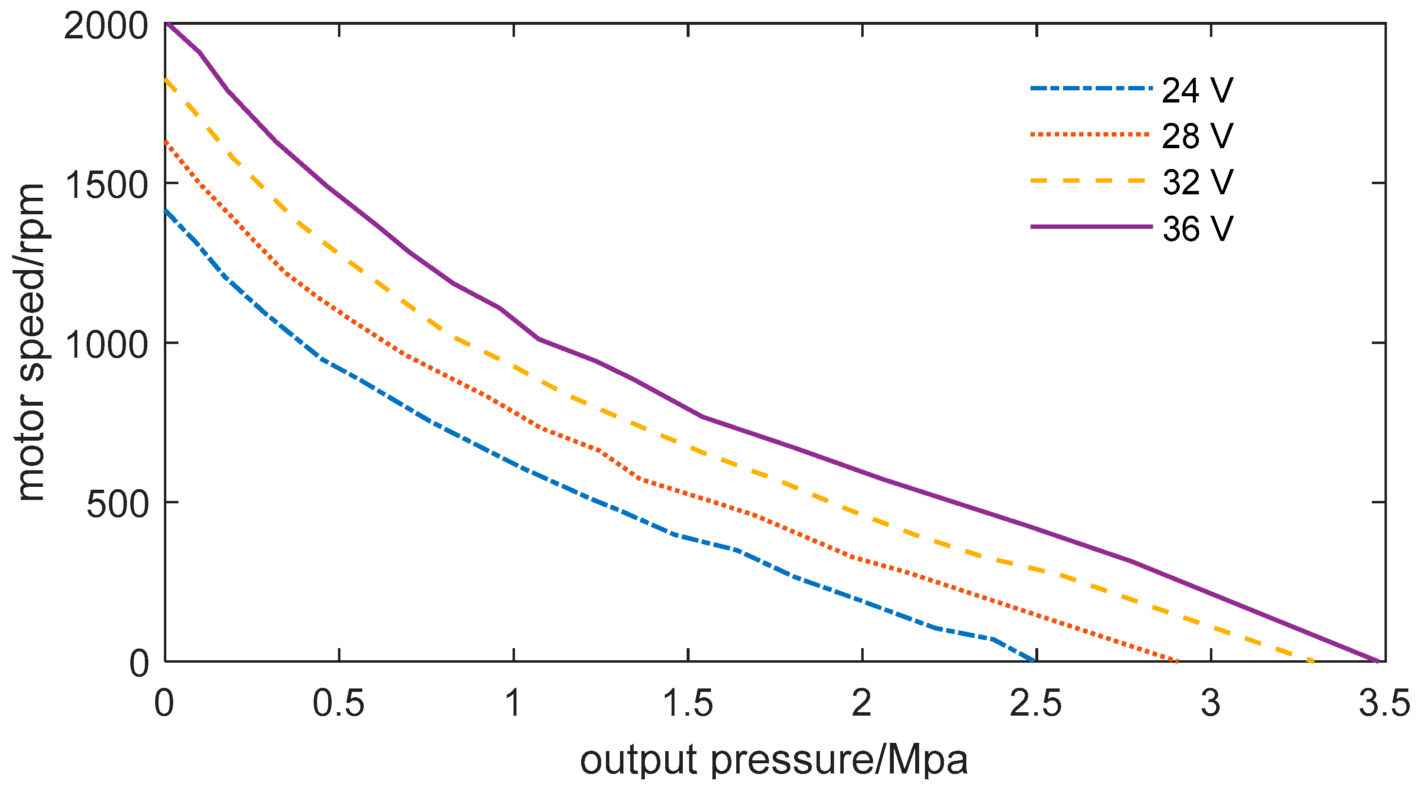
When the operating conditions of the proposed IEHVP change, assuming that its outlet pressure increases, the speed loss caused by the outlet pressure will increase, and the motor speed will decrease. At the same time, the friction torque loss caused by the speed begins to decrease, and the two together affect the motor rotation speed until the motor output torque is equal to the external consumption torque; the IEHVP runs stably in this state. Based on the relevant data, the corresponding relationship between the speed of the IEHVP and its outlet pressure can be obtained, as shown in Figure 7:
It can be seen from Figure 7 that when ignoring the impact of temperature change on the performance of the IEHVP, the speed change of the integrated electro-hydraulic pump is not linearly related to the change of outlet pressure due to the existence of motor winding inductance.
When the outlet pressure is constant, the speed of the internal motor can be changed by adjusting the voltage loaded at both ends of the IEHVP to realize the regulation of the output flow, which can also be called the regulation characteristics of the IEHVP. When considering the flow leakage caused by pressure, the operating characteristics of the IEHVP are shown in Figure 8:
Figure 8 reveals that the output flow of the IEHVP can be linearly changed by adjusting the loading voltage when the outlet pressure is constant. Otherwise, when the voltage is constant, the output flow of the IEHVP decreases non-linearly with the increase of outlet pressure. It is worth noting that when the pressure exceeds a specific range, the IEHVP can no longer output oil due to excessive internal leakage. For instance, it appears that when the input voltage is 36 V and the outlet pressure exceeds 2.5 Mpa. Therefore, we should pay attention to setting the range of its outlet pressure to avoid resource waste.
4. Experimental Study on Integrated Electric Hydraulic Vane Pump
This section mainly introduces the test device, test system, and test method of the integrated electric hydraulic vane pump prototype. Through the test, the influence of the speed of the IEHVP on its volumetric efficiency when the outlet pressure is 0.5 MPa, and the influence of the outlet pressure on its speed and output flow under different loading voltages are measured. Therefore, the performance of the prototype can be obtained.
The test is conducted according to the designed connecting pipeline in Figure 9. The IEHVP is in continuous operation during the test, and the hydraulic system built in this test is a closed circuit. During the test, the temperature of the integrated electric hydraulic pump is maintained between 36~45 °C, which is smaller than the simulation result. The main reason is that the IEHVP does not operate long enough at its rated state. When the overflow valve is fully open, there is still an inevitable pressure loss because the oil flows along the pipeline in the test system. At this time, the measured outlet pressure of the integrated electric hydraulic pump is about 0.5 MPa. In this case, the influence of oil on the motor speed and the relationship between the volumetric efficiency of IEHVP and motor speed can be obtained in Table 1.
It can be seen from Figure 10 and Table 1 that, whether in a typical environment or an oil-immersed environment, the motor speed increases linearly with the increase of its load voltage. Under the same input voltage, the speed of the motor in a typical environment is greater than that in an oil-immersed environment. The difference between the two conditions becomes larger as the voltage increases. The difference between the two conditions at 24 V is 305 rpm, and when the input voltage is 40 V, the difference is expanded to 678 rpm. The reason is that with the increase of the speed, the viscous load torque that the motor needs to overcome is greater, which in turn inhibits the increase of the motor speed.
The volumetric efficiency of the IEHVP increases with the increase of speed at the beginning. When the speed reaches 1500~1700 rpm, the volumetric efficiency remains relatively stable, and the volumetric efficiency decreases slightly with the continuous increase of the speed. Because the leakage of the integrated electric hydraulic pump is only related to its outlet pressure, its volumetric efficiency increases with the increase of rotating speed when the leakage remains unchanged. However, the volumetric efficiency will not increase or decrease slightly when the rotating speed exceeds a specific value. The reason for this is that the structure of the oil suction channel of the IEHVP has been determined. Although the rotating speed is very fast during actual operation, the vane pump cannot absorb enough oil in the oil suction area in time, its internal cavitation becomes serious, and the volumetric efficiency cannot continue to increase.
Figure 11 and Figure 12 respectively show the influence of the tested outlet pressure of the IEHVP on its internal motor speed and output flow. The test results show that within 0~3 MPa, the motor speed and the output flow of the IEHVP show a gradual downward trend with the increase of outlet pressure. When the input voltage is 36 V, and the outlet pressure is 0.5 MPa, the speed and flow of the IEHVP reach the maximum values of 1715 rpm and 8.2 L/min, respectively. However, when the outlet pressure exceeds 3.5 MPa, the motor speed-driven under 24 V and 28 V does not change. Although the motor is still operating, the IEHVP no longer outputs oil to the outside. Through analysis, there are many reasons for this result, among which the main reason may be that there are large errors in the processing and assembly process of the parts of the integrated electric hydraulic vane pump prototype. The increase in the error and the decrease in the dimensional accuracy of the parts will make the internal leakage of the IEHVP more serious. Therefore, when the outlet pressure exceeds a specific value, although the motor is still rotating, all the oil that should be discharged outward by the balanced vane pump returns to the low-pressure area through various leakage paths, which causes the IEHVP not to output oil again. At this time, even if the opening pressure of the overflow valve is increased again, it will no longer have any impact on the speed of the motor. In addition, it can be seen that, when the outlet pressure of the IEHVP is within 0~3 MPa, the speed and output flow of the motor increase linearly with the increase of the input voltage. Due to the limitation of test conditions, it is temporarily impossible to ascertain whether the speed and output flow of the IEHVP change non-linearly when the outlet pressure changes continuously.
As shown in Figure 13, under different input voltages, the volumetric efficiency of the IEHVP decreases with the increase of outlet pressure. When the outlet pressure is 0.5 MPa, the maximum volumetric efficiency of the electric hydraulic pump under each input voltage reaches 78~88%. With the increase of outlet pressure, the volumetric efficiency decreases sharply. When the outlet pressure reaches 4 MPa, the volumetric efficiency reaches the minimum value. In addition, when the outlet pressure is constant, the volumetric efficiency of the IEHVP increases with the increase of the input voltage.
5. Conclusions
In this paper, a novel integrated electric hydraulic vane pump (IEHVP) is designed, composed of an external rotor brushless DC motor and a balanced vane pump. The external characteristic curve of the designed IEHVP is obtained by coupling analysis of the operating characteristics. When the outlet pressure is constant, the output flow has a linear relationship with the loading voltage. The voltage is higher, and the output flow is greater. When the loading voltage is constant, its output flow will decrease with the increase of outlet pressure. However, there is no nonlinear correlation between them. Although the motor is still rotating when the outlet pressure is too high, the device will no longer output oil due to excessive internal leakage. Finally, the prototype of an IEHVP is tested. The test results show that the oil has a noticeable blocking effect on the operation of the IEHVP. When the outlet pressure is 0.5 MPa, the volumetric efficiency of the IEHVP will increase with the increase of speed. When the speed reaches 1500~1700 rpm, the volumetric efficiency will remain in a stable range. When the speed continues to increase, the volumetric efficiency will decrease slightly. When the outlet pressure changes within 0~3 MPa, the speed and output flow of the IEHVP decreases with pressure. When the input voltage is 36 V, and the outlet pressure is 0.5 MPa, the speed and flow of the IEHVP reach the maximum values of 1715 rpm and 8.2 L/min, respectively. At this time, the maximum volumetric efficiency is 87%. When the input voltage is constant, the volumetric efficiency of the IEHVP decreases with the increase of the outlet pressure. When the outlet pressure is constant, the volumetric efficiency increases with the increase of the input voltage.
In future work, in order to more accurately obtain the distribution of the internal flow field and temperature field of the integrated electric hydraulic pump, it is necessary to carry out the two-way coupling of magnetism, heat, and heat and flow.
Author Contributions
Conceptualization, methodology, and software, Y.W.; validation, Y.W. and W.Y.; formal analysis, Y.W. and W.Y.; investigation, Y.W. and W.Y.; resources, Y.W. and W.Y.; data curation, Y.W. and W.Y.; writing—original draft preparation, Y.W.; writing—review and editing, Y.W.; supervision, Y.Y.; funding acquisition, W.Z. All authors have read and agreed to the published version of the manuscript.
Funding
This work was supported by the Central University Basic Research Fund of China (No. FRF-TP-20-054A1), Guangdong Basic and Applied Basic Research Foundation (No. 2021A1515110195), Shunde Graduate School of University of Science and Technology Beijing.
Institutional Review Board Statement
Not applicable.
Informed Consent Statement
Not applicable.
Data Availability Statement
Not applicable.
Conflicts of Interest
The authors declare no conflict of interest.
References
- Li, J.; Tang, H.; He, C. Experimental Research on the Dynamic Characteristics of a Deep-Sea Nodule Collector Track. In Proceedings of the Fourteenth ISOPE Pacific/Asia Offshore Mechanics Symposium, Dalian, China, 22–25 November 2020; International Society of Offshore and Polar Engineers: Houston, TX, USA, 2020. [Google Scholar]
- Kang, Y.; Liu, S.; Zou, W.; Zhao, H.; Hu, X. Design and analysis of an innovative deep-sea lifting motor pump. Appl. Ocean Res. 2019, 82, 22–31. [Google Scholar] [CrossRef]
- Nie, S.; Guo, M.; Yin, F.; Ji, H.; Ma, Z.; Hu, Z.; Zhou, X. Research on fluid-structure interaction for piston/cylinder tribopair of seawater hydraulic axial piston pump in deep-sea environment. Ocean Eng. 2021, 219, 108222. [Google Scholar] [CrossRef]
- Chaoyou, Z.; Yakui, G.; Xia, L. A distributed system for aircraft hydraulic systems simulation test based on LXI. In Proceedings of the 2008 IEEE Autotestcon, Salt Lake City, UT, USA, 8–11 September 2008; IEEE: New York, NY, USA, 2008; pp. 185–188. [Google Scholar]
- Ji, H.; Wang, W.; Wang, J.; Zhang, J. Performance test and analysis of the prototype of the electric motor-pump. Proc. Inst. Mech. Eng. Part C J. Mech. Eng. Sci. 2015, 229, 3027–3033. [Google Scholar] [CrossRef]
- Zhu, D.; Fu, Y.; Han, X.; Li, Z. Design and experimental verification on characteristics of electro-hydraulic pump. Mech. Syst. Signal Process. 2020, 144, 106771. [Google Scholar] [CrossRef]
- Chen, H.; Liu, W. Research on the feature of hydraulic oil of electro-hydraulic pump. In Proceedings of the 2012 Proceedings of International Conference on Modelling, Identification and Control, Wuhan, China, 24–26 June 2012; IEEE: New York, NY, USA, 2012; pp. 52–56. [Google Scholar]
- Tomov, P.; Yanulov, D. Modelling the Processes of Hydraulic Commutation in an Electro-Hydraulic Pumping Unit Driven by an Asynchronous Motor. In Proceedings of the 2019 16th Conference on Electrical Machines, Drives and Power Systems (ELMA), Varna, Bulgaria, 6–8 June 2019; IEEE: New York, NY, USA, 2019; pp. 1–4. [Google Scholar]
- Han, X.; Fu, J.; Minav, T.; Fu, Y.; Pietola, M. Modelling Method of the Direct Drive Valve with Limited Information for More Electric Aircraft Applications. In Proceedings of the 2018 IEEE International Conference on Electrical Systems for Aircraft, Railway, Ship Propulsion and Road Vehicles & International Transportation Electrification Conference (ESARS-ITEC), Nottingham, UK, 7–9 November 2018; IEEE: New York, NY, USA, 2018; pp. 1–6. [Google Scholar]
- Fu, Y.; Gou, Z.; Wang, M.; Zhu, D.; Lin, Z. Design and Experimental Verification on Characteristics of Local Electro-Hydraulic Generation System. In Proceedings of the 2020 IEEE International Conference on Mechatronics and Automation (ICMA), Beijing, China, 13–16 October 2020; IEEE: New York, NY, USA, 2020; pp. 389–394. [Google Scholar]
- Rui, G.; Zhiqian, Z.; Jinsheng, Z.; Jingyi, Z.; Zhe, Y.; Dianrong, G. Reliability Evaluation of Piston Pump Based on Comprehensive Evaluation Index. J. Test. Eval. 2020, 49. [Google Scholar] [CrossRef]
- Fiebig, W.; Cependa, P.; Jedraszczyk, P.; Kuczwara, H. Innovative solution of an integrated motor pump assembly. In Proceedings of the ASME/BATH 2017 Symposium on Fluid Power and Motion Control, Sarasota, FL, USA, 16–19 October 2017; American Society of Mechanical Engineers: New York, NY, USA, 2017; p. V1T. [Google Scholar]
- Fiebig, W.; Ignacy, D.; Marek, C.; Hubert, K. A vane pump integrated with an electric motor. In Proceedings of the 9th International Fluid Power Conference, Aachen, Germany, 24–26 March 2014; pp. 24–26. [Google Scholar]
- Fu, Y.; Zhang, M.; Qi, H.; An, G. Application of heat pipe technology in the design of hydraulic motor pump. In Proceedings of the 2011 International Conference on Electronic & Mechanical Engineering and Information Technology, Harbin, China, 12–14 August 2011; IEEE: New York, NY, USA, 2011; pp. 1033–1036. [Google Scholar]
- Hong, J.; Qi, Q.; Zheng-Rong, W.; Qihui, H. A novel design of hydraulic motor-vane pump with auxiliary centrifugal pump. In Proceedings of the 5th International Symposium on Fluid Power Transmission and Control, Beidaihe, China, 6–8 June 2007; pp. 141–144. [Google Scholar]
- Wang, J.-L.; Ji, H.; Ren, C.-Y.; Zhang, X.-W.; Ren, W.; Zhang, J.-M.; Cao, Q.-H. Efficiency Analysis for Electric Motor-vane Pump Prototype with Port-plate Centrifugal Pump. Chin. Hydraul. Pneum. 2017, 93–97. [Google Scholar] [CrossRef]
- Hong, J.I.; Wang, X.L. Influence of Motor Stator Shape on Electro-magnetic Characteristics in Hydraulic Motor Pump. Mach. Tool Hydraul. 2013, 5, 5–8. [Google Scholar]
- Drobny, J. Properties of terpolymers of ethylene, tetrafluoroethylene and hexafluoropropylene. In Specialty Thermoplastics; Springer: London, UK, 2015; pp. 45–47. [Google Scholar]
- Fu, Y.; Li, Z.; Qi, X.; Fan, D. Research on the energy conversion efficiency of axial piston electro-hydraulic pump. J. Mech. Eng. 2014, 50, 204–212. [Google Scholar] [CrossRef]
- Qi, Q.; Ji, H. Simulation and Analysis of special Motor of the hydraulic Motor-Vane Pump Based on Ansoft. In Applied Mechanics and Materials; Trans Tech Publications Ltd.: Stafa-Zurich, Switzerland, 2012; pp. 603–609. [Google Scholar]
- Ji, H.; Sun, L.; Xu, D.; Ding, D.; Wang, Z. The efficiency analysis of an electric, motor-pump with port-plate centrifugal pump. In Proceedings of the Seventh International Conference on Fluid Power Transmission and Control, Hangzhou, China, 7–10 April 2009. [Google Scholar]
- Gao, D.; Liu, J.; Wen, M. Analysis of internal flow field of a new axial piston hydraulic motor pump. J. Yanshan Univ. 2010, 34, 483–500. [Google Scholar]
- Inaguma, Y.; Hibi, A. Reduction of friction torque in vane pump by smoothing cam ring surface. Proc. Inst. Mech. Eng. Part C J. Mech. Eng. Sci. 2007, 221, 527–534. [Google Scholar] [CrossRef]
- Frosina, E.; Senatore, A.; Buono, D.; Stelson, K.A.; Wang, F.; Mohanty, B.; Gust, M.J. Vane pump power split transmission: Three dimensional computational fluid dynamics modeling. In Proceedings of the ASME/BATH 2015 Symposium on Fluid Power and Motion Control, Chicago, IL, USA, 12–14 October 2015; American Society of Mechanical Engineers: New York, NY, USA, 2015; p. V1T. [Google Scholar]
- El Ashmawy, M.; Murrenhoff, H. Experimental investigation of friction force between vane tip and cam-ring in oil vane pumps. Int. J. Fluid Power 2009, 10, 37–46. [Google Scholar] [CrossRef]
Figure 1.
EPAI of VOITH.

Figure 2.
The hydraulic motor vane pump designed by Ji Hong.

Figure 3.
RP series rotary pump of Daikin Company, Osaka, Japan.

Figure 4.
The integrated electric hydraulic pump designed by Beihang University.

Figure 5.
The proposed IEHVP, 1-Front end cover, 2-Front oil distribution side plate, 3-vane pump stator, 4-blade, 5-pin, 6-rear oil distribution side plate, 7-Outer rotor motor, 8-Rear cover, 9-support shaft, 10-Needle bearing, 11-Vane pump rotor, 12-oil tank shell, 13-Fuel tank cap, 14-Locating pin, 15-Flange Bolt, a1-flange sealing ring, a2&a3-pump body sealing ring, b1-Oil hole in the rear end cover, b2-Vane pump stator oil through-hole, b3-Front end cover oil hole, c1&c2-front and rear end cover pressure compensation oil groove, I-Inner cavity of fuel tank, II-Sector suction area, III-Power cord extension port, IV-Vane pump oil outlet.

Figure 6.
The energy conversion flowchart of the proposed IEHVP.

Figure 7.
The variation of motor speed with outlet pressure.

Figure 8.
The operating characteristics of the proposed IEHVP.

Figure 9.
The test bench of the proposed IEHVP.

Figure 10.
The influence of oil on motor speed and speed on volumetric efficiency.

Figure 11.
The influence of outlet pressure on motor speed.

Figure 12.
The influence of outlet pressure on output flow.

Figure 13.
The influence of outlet pressure on volumetric efficiency.


Table 1.
The influence of oil on motor speed.
| Voltage (V) | Rotation Speed in the Non-Oil-Immersed Environment (rpm) | Rotation Speed in Oil-Immersed Environment (rpm) | Output Flow (L/min) |
|---|---|---|---|
| 24 | 1540 | 1235 | 5.2 |
| 26 | 1668 | 1310 | 5.8 |
| 28 | 1807 | 1362 | 6.0 |
| 30 | 1926 | 1458 | 6.6 |
| 32 | 2057 | 1570 | 7.5 |
| 34 | 2180 | 1650 | 7.8 |
| 36 | 2310 | 1715 | 8.2 |
| 38 | 2420 | 1800 | 8.5 |
| 40 | 2560 | 1882 | 8.9 |
Publisher’s Note: MDPI stays neutral with regard to jurisdictional claims in published maps and institutional affiliations. |
© 2022 by the authors. Licensee MDPI, Basel, Switzerland. This article is an open access article distributed under the terms and conditions of the Creative Commons Attribution (CC BY) license (https://creativecommons.org/licenses/by/4.0/).
Share and Cite
MDPI and ACS Style
Yang, W.; Wang, Y.; Yang, Y.; Zhang, W. Design and Experimental Verification on Performance of a Novel Integrated Electro-Hydraulic Vane Pump. Appl. Sci. 2022, 12, 5006. https://0-doi-org.brum.beds.ac.uk/10.3390/app12105006
AMA Style
Yang W, Wang Y, Yang Y, Zhang W. Design and Experimental Verification on Performance of a Novel Integrated Electro-Hydraulic Vane Pump. Applied Sciences. 2022; 12(10):5006. https://0-doi-org.brum.beds.ac.uk/10.3390/app12105006
Chicago/Turabian StyleYang, Weiwei, Yilin Wang, Yaodong Yang, and Wenming Zhang. 2022. "Design and Experimental Verification on Performance of a Novel Integrated Electro-Hydraulic Vane Pump" Applied Sciences 12, no. 10: 5006. https://0-doi-org.brum.beds.ac.uk/10.3390/app12105006
Note that from the first issue of 2016, this journal uses article numbers instead of page numbers. See further details here.