1. Introduction
Among the various failures of induction motors, the most common defect is in bearings. Bearing failures shows a high percentage of failures when compared to other faults, such as short-circuits, broken rotor bars, and eccentricities [
1]. The role of the bearing is not limited to electrical motors but also extends to various mechanical components, and it stands to be a vital component. The early identification of bearing faults may prevent and reduce high mending costs and maintenance costs. Additionally, the early prevention of faults may have the effects of not decreasing the production quantity and not extending breaktime. Thus, induction motor conditions, especially bearing conditions, should be monitored for healthy production.
In most existing studies, pitting has been considered a fault factor, and vibration-based analyses have been used primarily to diagnose bearing faults [
2]. However, the acquisition of vibration data requires transducers or accelerometers, which makes this method expensive. An alternative method, namely, motor current signature analysis, is easier to implement and more affordable because it eliminates the positioning of sensors [
3]. However, this method cannot identify the present state of a motor. Over the past years, acoustic emission (AE) sensors have been used in bearing condition monitoring and fault diagnosis [
4]. AE signals can capture bearing fault features and detect incipient faults [
5,
6]. Detection is performed using the frequencies of selected components as key features. For rotating machinery systems, the Hilbert Huang transform (HHT) is used with AE signals to detect faults [
7]. The application of digital signal processing has been extended to identify the bearing failure of induction machines [
8]. Generally, raw signals are insufficient to identify failures. Therefore, for fault identification, features are extracted from the time and frequency domain analyses. The root means square method [
9], high-order statistical method [
10], and short impulse method [
11] are examples of time domain analysis approaches.
A linear discriminant analysis was also performed on stator currents for fault diagnosis, and further diagnosis was conducted with a Bayesian classifier [
12]. This technique recognized damage with large-diameter pitting. Infrared thermography fault diagnosis methods based on image processing have also been proposed [
13]. However, their usage has been limited, and successful results were observed only in DC machines [
14]. In wound-rotor induction motors, infrared data analysis provided useful information about defects and present motor conditions [
15]. In most cases, this method is applicable and is performed offline. Although infrared techniques have immense potential for fault detection, their cost is high due to the need for data acquisition devices and infrared cameras [
16]. A comparison study on vibration and current signal analysis was published [
17].
The number of intelligent diagnosis methods for identifying defects is rapidly increasing, and adaptive neuro-fuzzy inference systems [
18,
19,
20,
21,
22,
23] and artificial neural networks (ANNs) [
19,
20,
21,
22] have often been applied. In general, intelligent bearing fault diagnosis involves two steps: feature extraction and classification [
19]. However, intelligent methods used in bearing fault diagnosis have some inherent disadvantages. Most of the fault categories belong to a single pitting (hole) fault, and compound faults have been discussed in some cases. Moreover, most intelligent systems are nonlinear and belong to shallow learning models. Their accuracy varies with the selection of features, largely depends on the diagnosis model, and requires engineering experience [
24]. Some authors published a pioneering work on failure diagnosis using deep learning [
25]. Recently, support vector machines (SVMs) have been widely used to diagnose stator winding faults [
26,
27] and wind turbine issues [
28]. Additionally, recently, machine learning techniques have been extended to other fields such as the smart optimization of the friction-drilling process and abrasive waterjet machining [
29,
30].
In most papers on bearing failure diagnosis, a pitting or a hole on the outer raceway has been treated as a fault factor. The existing fault diagnosis methods have detected the holes with good accuracy but lack the detection of scratch failures. Thus, the drawbacks of validating faults other than pitting were evaluated in the present method proposed. The versatility of a fault diagnosis method is important from a practical standpoint. The present paper aims to illustrate the potential of a proposed convolutional neural network (CNN)-based method in bearing fault diagnosis (scratch detection and scratch traceability analysis). To avoid a low detection percentage and overlapping effects, both the hidden layer and pooling layer are optimized, and epochs are performed. Comparing the general CNN techniques, in the proposed CNN method, an auto-tuning parameter optimization function is added to tune the hidden layer and the pooling layer. This makes the system able to reduce the effect of overlapping and increases the accuracy rate. A detailed analysis is discussed in
Section 4. In a detailed analysis of scratch traceability, concentrated scratches are considered faults. Scratches are more likely to occur at sites compared with pitting, but they have seldom been considered. Finally, for validation, a scratch is induced away from the center (offset to the outer raceway of the bearing) and diagnosed using the proposed CNN method. The entire dataset used to perform CNN is given after performing an FFT analysis using the load current of the stator. Promising results are obtained and compared with other machine learning algorithms to enhance the performance of the proposed method.
2. Brief Explanation of Proposed Diagnosis Method
CNN is one of the commonly used deep neural network architectures for training unsupervised features. It is characterized by in-shift variance, weight sharing, a high accuracy rate, and data encoding [
27]. The proposed method is explained briefly in the following section.
2.1. Methodology
The load currents of healthy and faulty motors were recorded at given rotation speeds. The features for fault diagnosis were the amplitudes of the 30 and 90 Hz frequency components of the load current, which were obtained via fast Fourier transform (FFT) analysis. The bearing fault of a target motor was diagnosed with the abovementioned CNN algorithm.
2.2. Construction of CNN for Fault Diagnosis
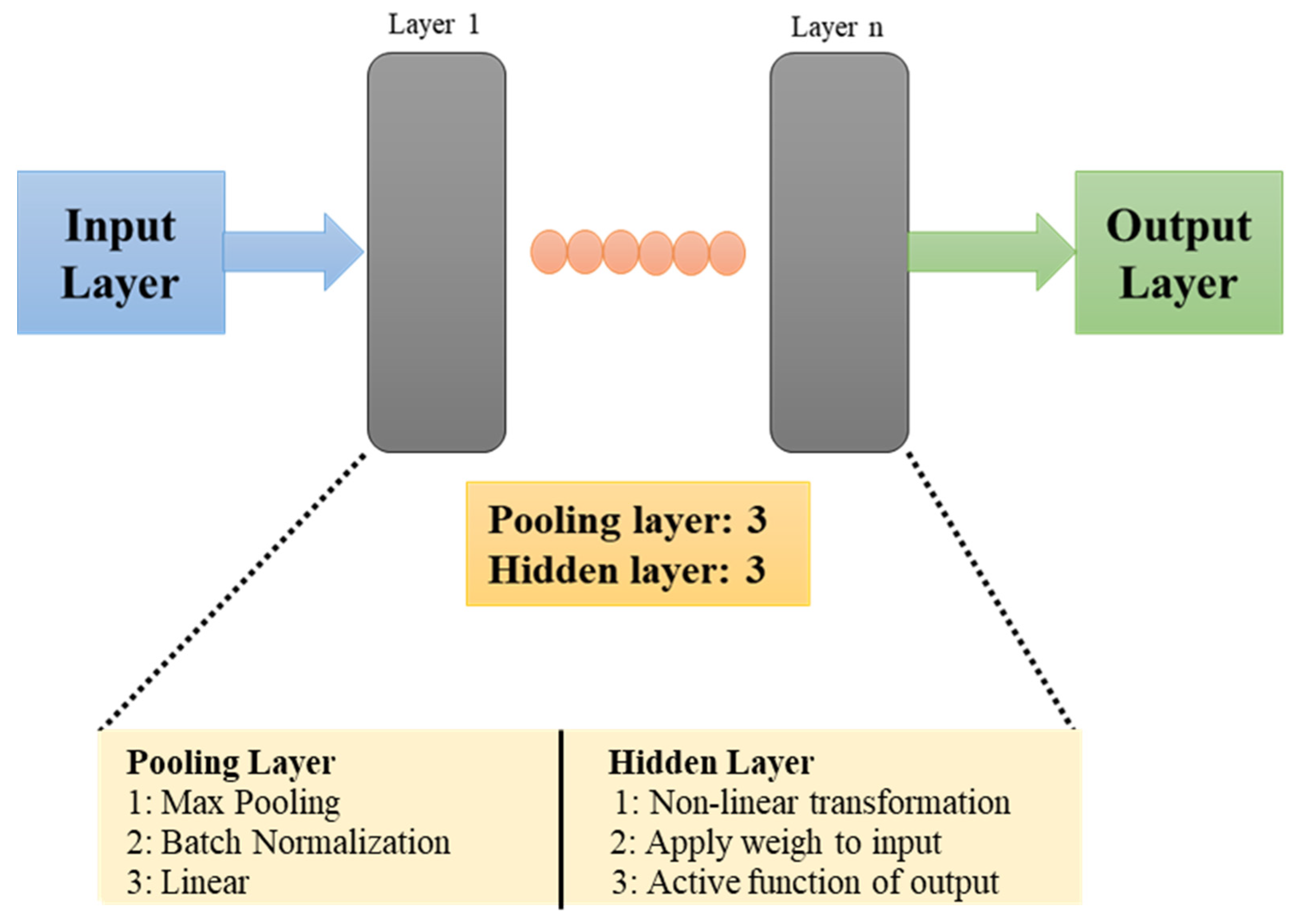
Typically, a CNN is composed of a feature extraction layer and a feature mapping layer. Neurons play a significant role in connecting these layers. The feature extraction layer consists of a local acceptable domain of the previous layer, which is connected through neurons. The local characteristics are extracted and forwarded to the feature mapping layer, which consists of multiple feature maps. Generally, a feature map is a plane filled with neurons, and it is followed by a calculation layer, which is used to calculate the features. The basic structure of a CNN model consists of input, hidden, and output layers. They are fully interconnected in one direction, from the input layer to the output layer, including a hidden layer and a pooling layer.
In our present study, the general structure of a CNN model was modified by adding an auto-tuning function. This auto-tuning function made adjustments to the hidden layer and pooling layer considering the accuracy rate and overlapping percentage. The details of the auto-tuning function are explained in the Procedures and Results of Diagnosis section. In our study, forward propagation in the CNN was performed, and the neurons in the hidden layer were decided based on the input and output patterns that must be recognized. The neurons in the hidden layer performed mathematical operations considering the number of inputs, and the post-mathematical operation results were given to output layer, where the final prediction was performed. These neurons of the hidden layer were expressed as the weight matrix and connected the adjacent layers (input and output layers). The output of the hidden layer can be mathematically expressed using Equation (1):
where W is weight expressed in matrix form, T represents transposition, X denotes input to the hidden layer, and b is the bias constant.
Apart from the basic model, in the proposed diagnosis system, an encoder was added with an auto-tuning function. In the basic model of a CNN, both the auto-tuning function and encoder are not attached; as a result, for each overlapping condition, a low accuracy rate is obtained. With the addition of auto-tuning and an encoder, automatic optimization of the hidden layer and pooling layer was made possible, and the missing data count was reduced. The results, evaluation, and drawbacks of the proposed method are discussed in
Section 4.
The structure of the model depends on the number of input data. In the present report, three types of bearing conditions are discussed (healthy, SS, and FS) and the structure of the encoder is framed considering three input data. The auto-encoder consisted of two parts: an encoder and a decoder. The encoder was used to extract features from the input data, which were given to the decoder for reconstructing the sampling data from the hidden layer. The weight parameters and the encoder and decoder bias vectors were adjusted according to the number of inputs, and the outputs were predicted.
A three-layer feed-forward propagation CNN was selected; both the input and output were defined as multiple variables without clear linear relationships. Considering the fault types and the number of dependencies, the proposed model consisted of three pooling layers and three hidden layers. A convolution layer was used for modeling and classification. A pooling layer was added to the basic structure to reduce the overlapping effects and to perform filtering and simple discretization. The proposed CNN model for bearing failure diagnosis is shown in
Figure 1.
3. Experimental Procedures and Results
This section explains the experimental setup, the artificial generation of faults, and the feature distributions of healthy and faulty bearings.
3.1. Experil Setup
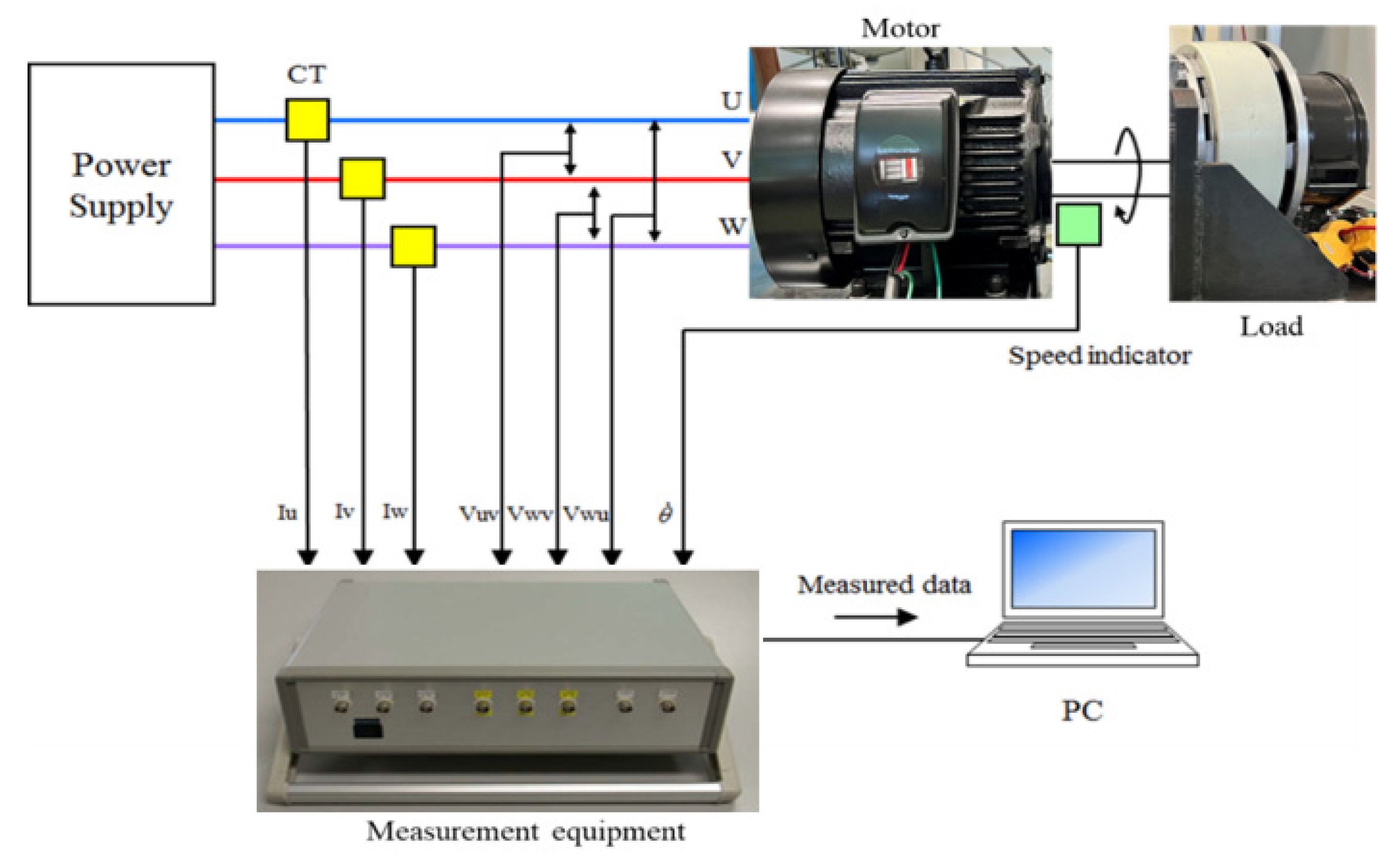
The experimental setup is shown in
Figure 2. A three-phase induction motor (2.2 kW, 200 V, 8.5 A, 1740 min
−1, four poles) was used as a specimen. The load was a powder brake. The rotation speed was set to 1780, 1775, 1770, and 1765 min
−1. The power supply frequency was 60 Hz.
The load currents and line-to-line voltages were measured using current probes (Hioki 9695-02) and voltage probes (Hioki 9666), respectively. The rotation speed was monitored with a speed indicator (Ono Sokki HT-5500). The output signals from these sensors were recorded on a notebook PC with measurement equipment developed by the authors and described in [
25]. It measured currents and voltages up to 20 A and 300 V, respectively, with a tolerance of ±2%. The sampling time was approximately 10 μs, and the frequency resolution was approximately 0.76 Hz. The data recording length was 2
17 per channel. The data acquisition was started by a trigger signal from a timer every 30 s, and data transfer to the PC was completed in less than 20 s. Only the U-phase load current of the stator was used in bearing failure analysis. The load currents of the V and W phases and the line-to-line voltages were regarded as references.
3.2. Artificial Generation of Bearing Faults
Collecting motors with bearing failures from factories is difficult and time-consuming. Thus, in this study, one out of several kinds of scratch faults was generated artificially on the surfaces of the outer raceways of bearings.
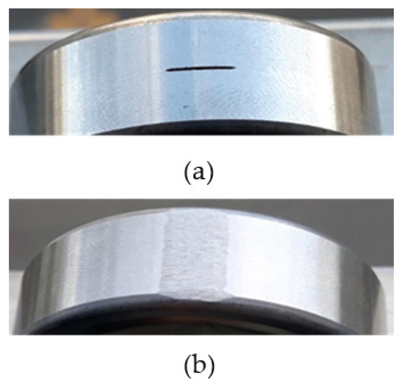
The single scratch (SS) and full scratch (FS) shown in
Figure 3 were considered basic-scratch faults. The SS had a length of 10 mm, a width of 0.5 mm, and a depth of 0.5 mm. The lengthwise direction was the circumference of the outer raceway. The scratch was located at the center width of the bearing thickness. The FS was formed with a file; it was 12 mm in length, 8 mm in width, and 0.5 mm in depth.
Additionally, faults with multiple concentrated scratches (CS) were considered. Parallel scratches were generated on the outer raceway. Each scratch had a length of 10 mm, width of 0.5 mm, and depth of 0.5 mm. The concentrated scratches with two parallel scratches were indicated as C2S and four parallel scratches as C4S. The dimensions were stated for C2S as two parallel scratches 0.5 mm apart and, for C4S, as four parallel scratches 0.5 mm apart on the outer raceway of the bearing.
A healthy motor was tested first for reference. Then, the healthy bearing (H) was replaced with a faulty one for further testing.
3.3. Feature Distribution and Results
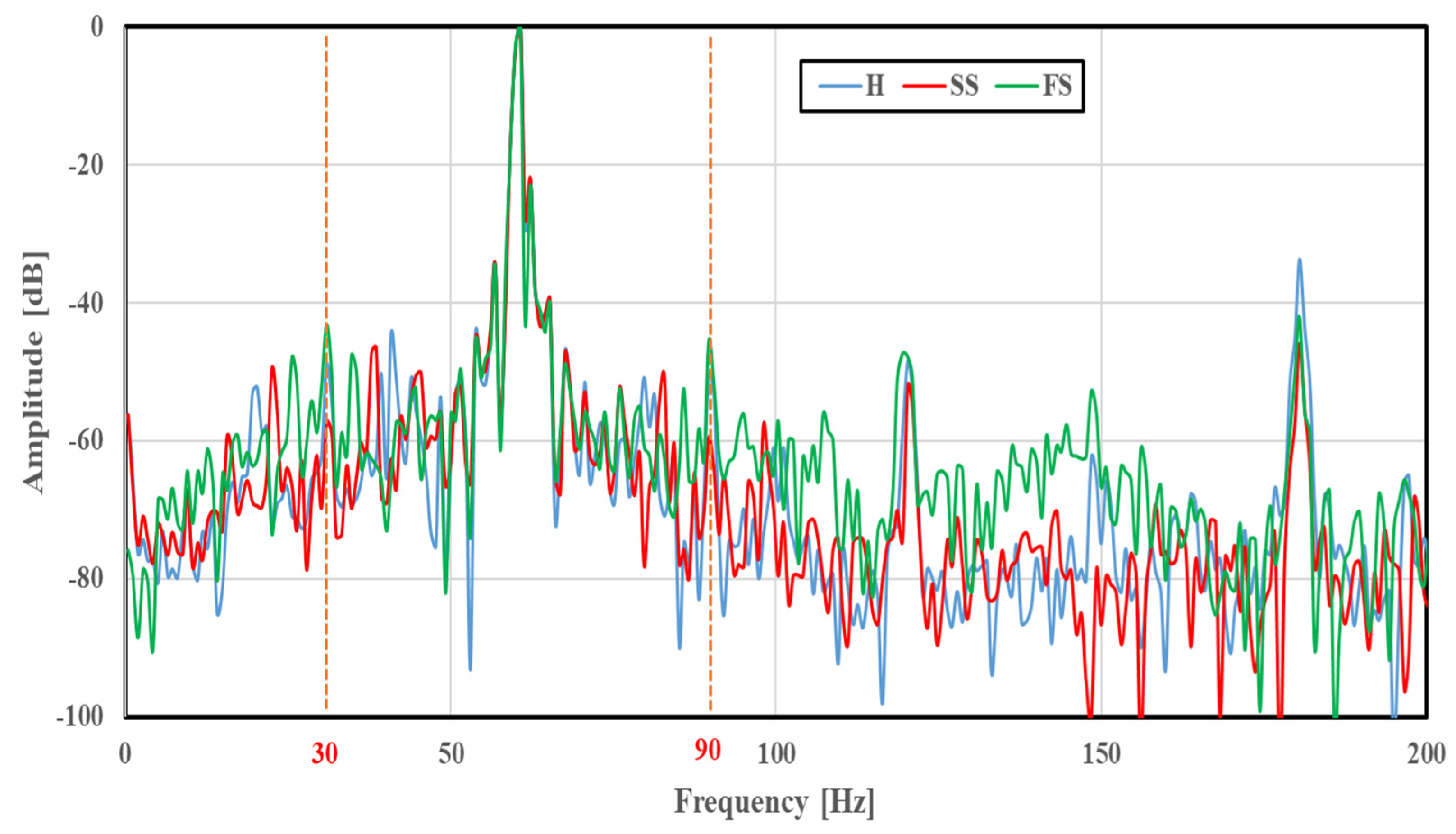
The FFT analysis was conducted using 283 U-phase stator current data obtained under various bearing conditions. First, the FFT analysis was performed for healthy motor where the bearing condition was healthy, followed by the other bearing conditions of SS and FS, respectively.
Figure 4 compares the frequency spectra of the basic scratch faults (SS and FS) with that of the healthy case (H) at a rotation speed of 1765 min
−1. Similarly, the frequency spectra of multiple faults at a rotation speed of 1780 min
−1 were calculated for concentrated and distributed scratch faults. The amplitude was normalized so that the maximum was 0 dB. At frequencies of 30 and 90 Hz, large amplitude differences were observed depending on the bearing conditions. A similar difference was also seen in spectra obtained at other rotation speeds.
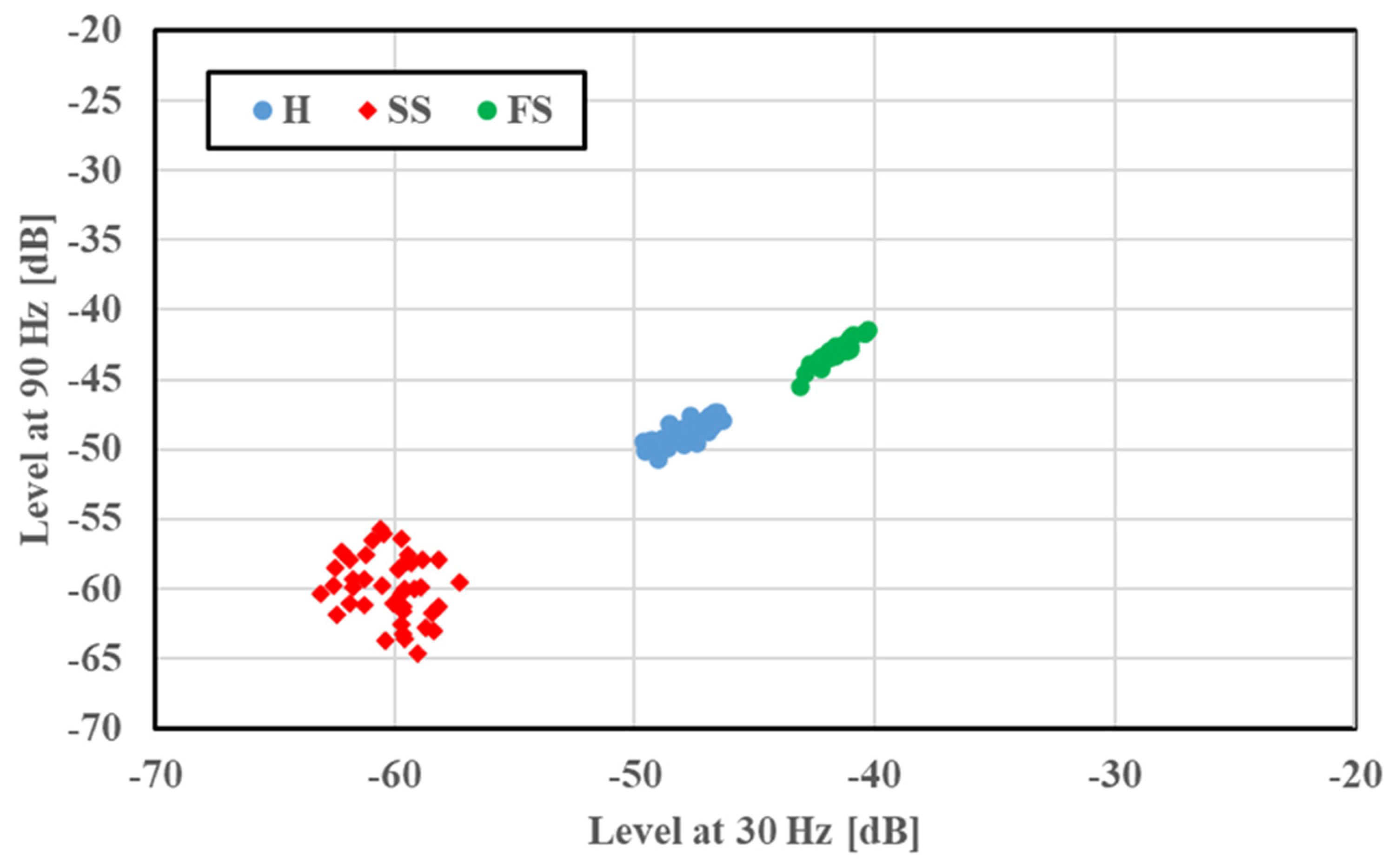
A two-dimensional display of the features was provided for fault classification; the amplitudes of the 30 and 90 Hz frequency components were plotted along the
x and
y axes, respectively. The feature distributions of SS and FS at 1765 min
−1 are illustrated in
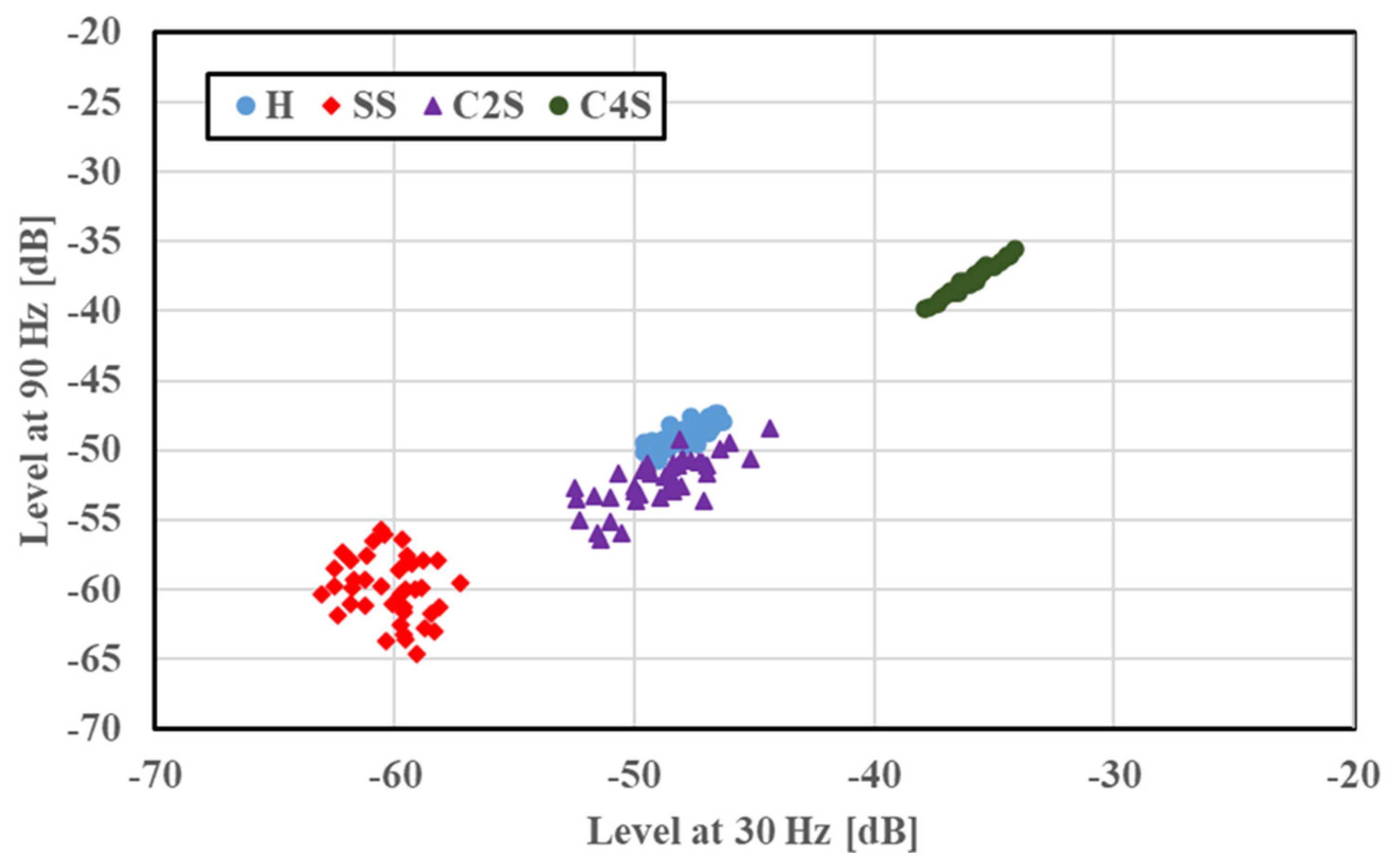
Figure 5. Features under a given bearing condition gathered in a certain region; a small amplitude was observed in the cases of SS and FS compared with H. This case had no overlapping of distribution regions, and the fault condition was easily identified. The feature distributions of the concentrated scratch faults (C2S and C4S) at 1765 min
−1 are shown in
Figure 6 for a multiple scratch analysis with H and SS. The features were localized depending on the faults, and a slight overlapping was evident. For the concentrated scratch faults, the amplitude increased with the number of scratches.
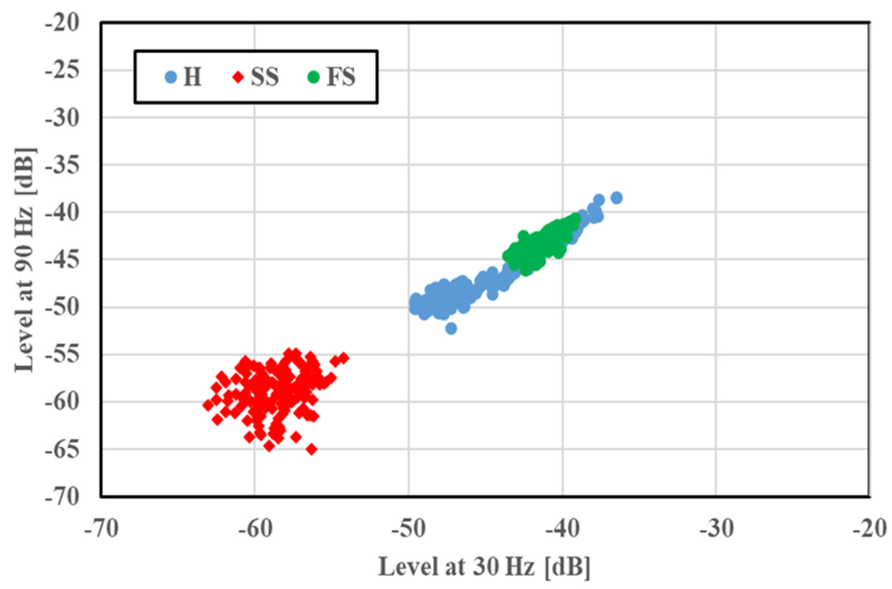
In factories, motor rotation speeds are not constant, and feature distribution is discussed without considering the rotation speed. The features of H, SS, and FS at four rotation speeds are merged and illustrated in
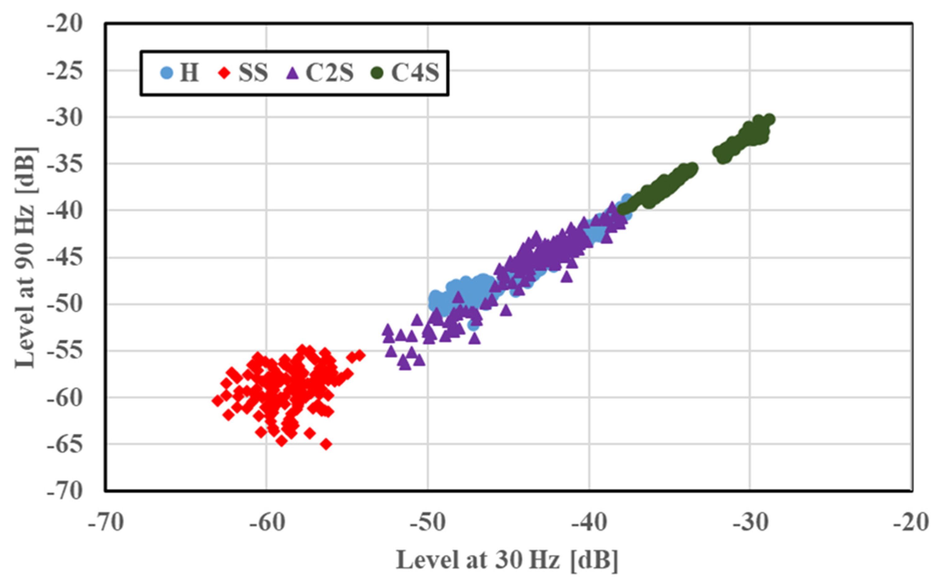
Figure 7. SS was diagnosed properly, even in this situation. However, H and FS showed overlapping features despite being distributed to their own classes. Since the feature distribution results of SS were extended along the results of H, differentiating the bearing conditions may be difficult. Thus, to predict the bearing condition effectively, further diagnosis was conducted using a deep learning model as a diagnostic tool. A similar trend and overlapping were observed in the case of the concentrated scratches, as shown in
Figure 8, and a diagnosis was performed using the CNN.
4. Procedures and Results of Diagnosis
This section explains the diagnostic results of the basic scratch faults and scratch traceability.
4.1. Diagnosis of Basic Scratch Faults
Diagnosis was performed on three types of bearing conditions (H, SS, and FS) without considering the rotation speed of the induction motor; the features obtained at four rotation speeds were merged. The datasets of the 30 and 90 Hz frequency components were divided into two groups randomly in a 70:30 ratio. Seventy percent of the data for each bearing condition (336 in total) was used for training, and the remaining 30% (144 in total) was used for diagnosis. Since DL follows a stack-flow method of diagnosis, H, SS, and FS took stack values of 0, 1, and 2, respectively.
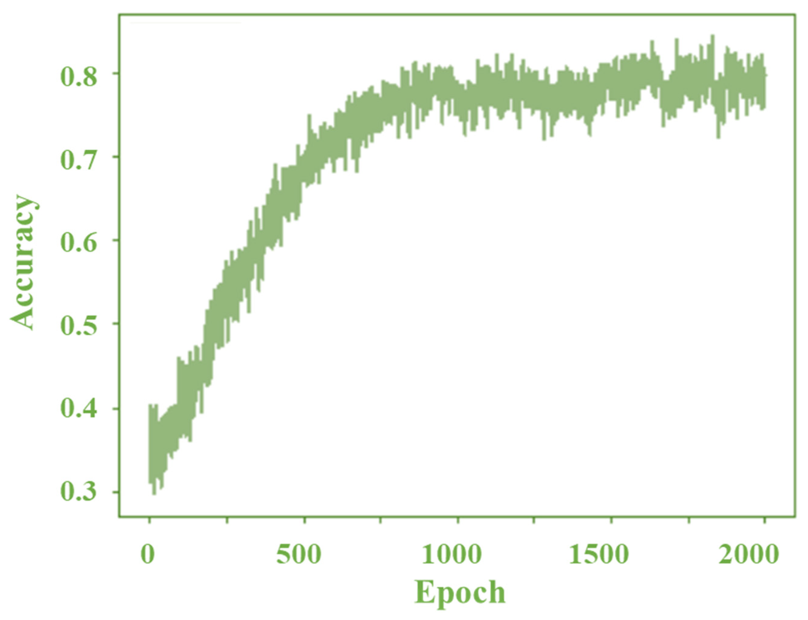
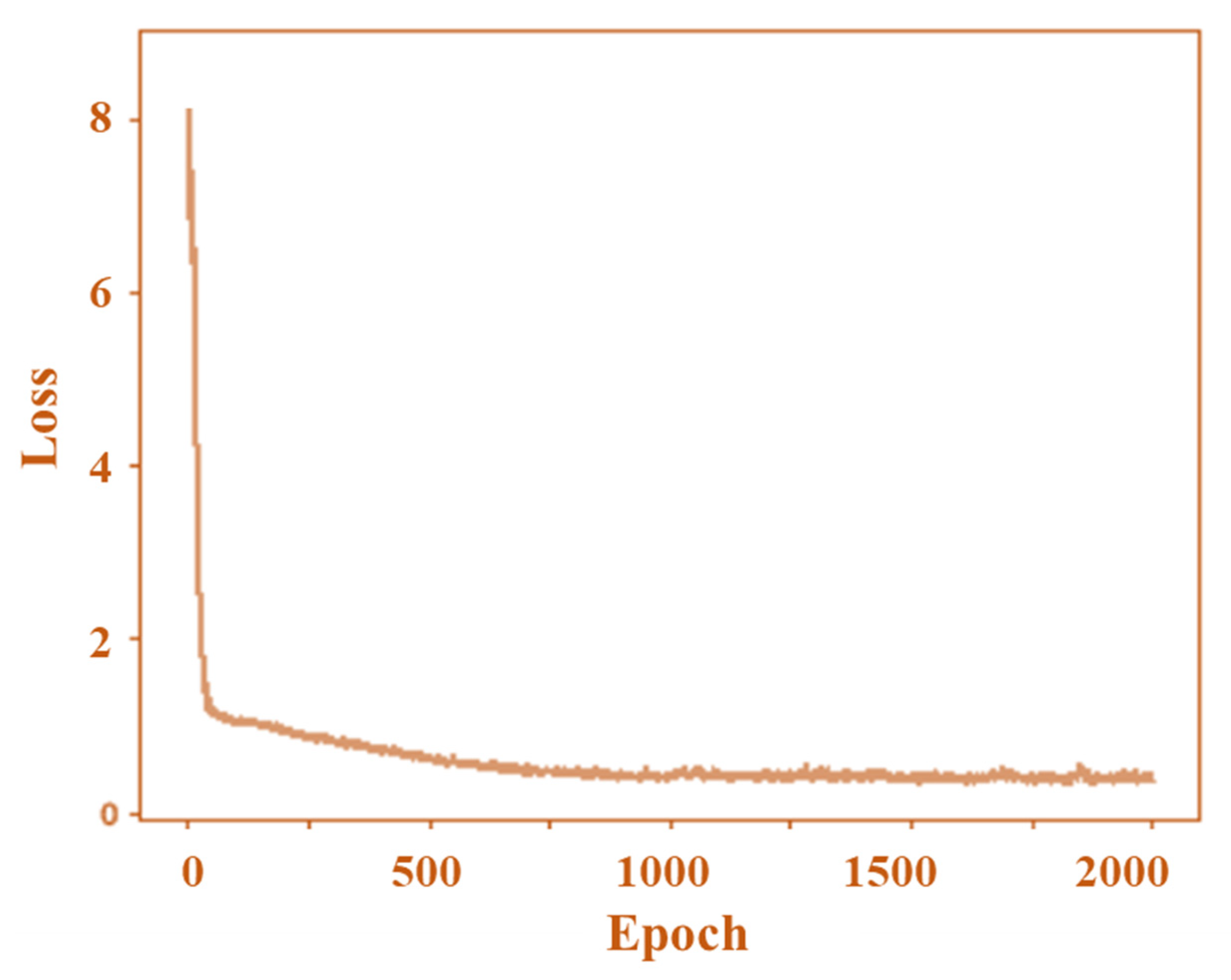
The epoch dependences of the accuracy rate and loss in H, SS, and FS diagnosis for the proposed method are shown in
Figure 9 and
Figure 10, respectively. The number of epochs was related to the number of optimization rounds required to train the data. The error performance or loss was reduced as the number of epochs increased. Therefore, the epoch needed to be selected carefully considering the available datasets. The relation between epoch and loss can be explained using Equation (2):
However, many epochs can make the network overfit the training data and degrade its performance. Therefore, the selection of epochs is important. A few iterations were conducted for the entire input dataset based on the epoch value. The number of iterations was set based on the batch size (number of training samples in one forward–backward pass). The accuracy rate increased with the epochs and reached 83.08% in this study, which was acceptable.
The diagnostic results of the basic scratch faults are given in
Table 1 where, for example, H–SS means a comparison between healthy and single scratch bearings. The accuracy rate of H–SS and SS–FS was 100%, indicating that the proposed method separated the two clusters and differentiated their bearing conditions. The differentiation of the three clusters (H–SS–FS) had a practically acceptable accuracy rate of 83.08%.
However, in the case of H–FS, the accuracy rate was 69.58%, which was lower than those of the other bearing class results. The FS sample had an almost flat outer raceway surface, and the shock wave pulse (generated when the balls of the bearing passed underneath the scratch) was nearly the same as that of H. This was the reason for the overlapping of features between H and FS, which resulted in a low accuracy rate. Further study is required to address overlapping and improve its diagnosis.
4.2. Discussion
In the present report, an auto-tuning function was embedded in the general model of a CNN to adjust the numbers of pooling layers and hidden layers automatically. Since the entire diagnosis process was performed without considering the rotating speed of the induction motor, in most of the cases the data were overlapping for different bearing conditions. The diagnosis process started with three hidden layers and three pooling layers as a minimum count and adjusted automatically due to the attachment of the auto-tuning function and encoder. In this paper, the main function of the encoder was to extract features from the input data and give them to the decoder for reconstructing the sampling data from the hidden layer. After each extraction, the hidden and pooling layers were tuned automatically using auto-tuning functions. The encoder was added to avoid missing data and to make the passage precisely. The idea was to increase the number of pooling layers and use a maximum function matrix to reduce the overlapping of features automatically.
On the contrary, if the overlapping percentage of the data features was above 70%, the auto-tuning function made a greater number of hidden and pooling layers (above 10). This made the possibility of the missing data percentage increase, resulting in a low accuracy rate (H–FS in
Table 1). Thus, further study is required to make the tuning function performance higher, even when the overlapping percentage is more than 70%.
On the other hand, during diagnosis when considering the rotation speed of an induction motor, an accuracy rate of 100% was obtained for any rotation speed. Excellent performance of the proposed method can be realized, for example, in a shipping test performed under a no-load condition.
4.3. Comparison with Other Machine Learning Algorithms
The performance of the proposed method was compared with other traditional methods, such as support vector machine (SVM), random forest (RF), decision tree (DT), k-means clustering (k-MC), and Gaussian mixture models (GMMs). The bearing fault of H–SS–FS was selected, and the diagnosis was performed. The parameters of each method were tuned optimally for proper comparison with the proposed method.
In the case of SVM, the accuracy is affected by three factors: the threshold function, the cost parameter (C), and the kernel function. In this study, radial basis function (RBF) was selected. The cost parameter was tuned through programming by selecting the optimum ranges. Based on these factors, an optimal hyperplane was selected, and data training was carried out for diagnosis. Furthermore, in the cases of DT and RF, considering the bearing fault feature selection, trees with branches and leaf nodes were constructed. Each node represented a feature (attribute), each branch represented a decision (rule), and each leaf represented an outcome (categorical or continuous value). The constructed DT reached its optional depth depending on parameter n, which was selected as 5 in the present study. For the case of RF, multiple DTs are constructed and, in the present study, three classes of DTs were selected and framed to form the RF. Between the three classes of DTs, selection of the variable was performed randomly, and the major voting was performed using the tree-bagging function to carry out the diagnosis. Similar optimal actions were executed for k-means clustering (k-MC) and Gaussian mixture models (GMM).
The results summarized in
Table 2 show the proposed CNN model had the highest accuracy rate when compared to other traditional methods. Its superiority arose from two main aspects: (1) its proper optimization reduced the error in the training process and (2) the constructed deep learning structure could be modified flexibly during diagnosis.
4.4. Traceability of Concentrated Scratch Faults
The features were loaded into the proposed CNN model, and the diagnosis was conducted without considering the rotation speed of the induction motor. The datasets of the 30 and 90 Hz frequency components were divided randomly into two groups in a 70:30 ratio. A total of 448 data samples were used for training, and 192 were diagnosis data. The data of each bearing condition were loaded in a stacked manner; H, SS, C2S, and C4S had stack values of 0, 1, 2, and 3, respectively.
The diagnostic results of the concentrated scratch faults are illustrated in
Table 3. Like the diagnostic results of the basic scratch faults, the diagnostic accuracy rate of the concentrated scratches was practically acceptable. H–C2S showed a low accuracy rate, and further study is required to eliminate the effect of overlapping. A high accuracy rate was obtained, and the number of scratches on the outer raceway of a bearing could be diagnosed. This result validated the proposed method and extended its application.
4.5. Validation of Proposed Method via Diagnosis of Offset Scratch
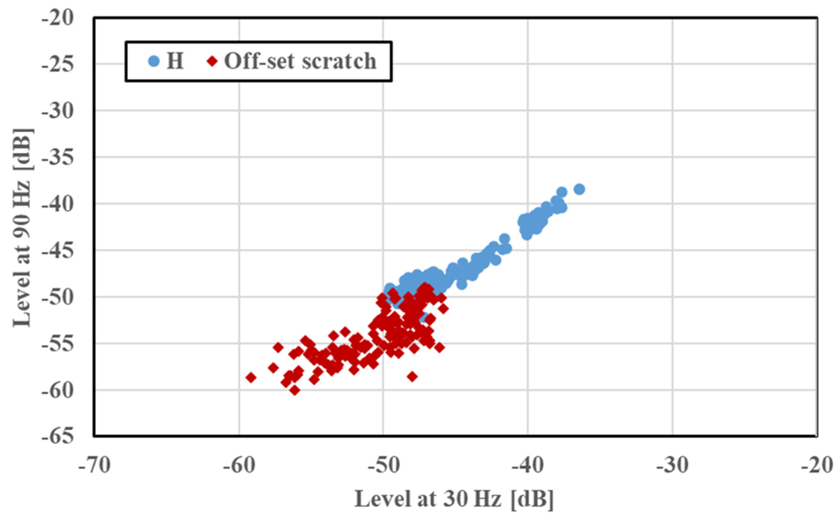
For validation and for checking the robustness of the developed method, the proposed CNN method was tested on an offset scratch. This scratch had a length of 10 mm, a width of 0.5 mm, and a depth of 0.5 mm and was generated away from the center (1.5 mm from the vicinity of the bearing). The experimental conditions were set to be like those of SS and FS, as described in
Section 3.1, for precise comparison and validation. The feature distribution of the offset scratch is shown in
Figure 11, and the rotation speed of the induction motor was not considered.
The features of the offset scratch (30 and 90 Hz) were loaded into the CNN model, and the diagnosis was performed as in the previous tests. The rotation speed of the induction motor was not considered in the diagnosis. The datasets of the 30 and 90 Hz frequency components were divided randomly into two groups in a 70:30 ratio. The diagnostic results of the offset scratch are presented in
Table 4. Even in this case, the accuracy rate of the diagnosis was high. However, as seen in
Figure 11, overlapping occurred between the feature distributions of healthy and faulty motors. Nonetheless, a high accuracy rate was obtained by disregarding the presence of overlapping between the two data features. Thus, the diagnosis accuracy rate was not affected by a change in the fault position, and the robustness of the proposed diagnostic system remained high. This high accuracy rate ensured position diagnosis and fault traceability. This validated the proposed method and extended its application.
5. Conclusions
The proposed CNN-based diagnostic method could differentiate a scratched bearing from a healthy one by solving the overlapping of features. The proposed method had the following advantages.
The type of scratch fault could be identified even when the data of four different rotation speeds were merged, considering the variation of rotation speed at the site;
The method identified the types of faults and the fault traceability;
The method was not affected by fault position, fault types, or even fault traceability, ensuring high robustness.
The proposed method offered not only versatility but also a competitive advantage in bearing fault diagnosis. High accuracy rates were obtained, validating the diverse applicability of the proposed method.
In future work, the proposed method should be tested on other kinds of faults, such as short-circuit faults and broken rotor bar faults. Furthermore, the authors aim to investigate the use of this method for other types of motors available in the industry.


 ,
, 


