1. Introduction
Industry 4.0 is a topic primarily debated in the literature, where many studies analyse enabling technologies and their applications by focusing on the impacts of Industry 4.0 on the specific process of manufacturing companies instead of considering all the processes in a holistic manner [
1,
2]. According to the review performed by Meindl et al. [
3], the literature has mainly been devoted to the study of smart manufacturing, although attention to the other smart dimensions, such as products and services, supply chain, and smart working, has increased in recent years. Thus, it supports the vision of Industry 4.0 as a fertile ground for exploring the smart manufacturing field, while simultaneously creating opportunities for synergies with other related smart fields by exploiting the capabilities of the most emerging technologies, such as IoT, ML, AI, big data, cloud computing, and additive manufacturing [
4,
5,
6].
Several recent works adopted the Industry 4.0 paradigm and technologies in different fields with clear advantages. Kechagias et al. [
7] focused on the maritime industry’s digital transformation, where security and safety are paramount in a similar multistakeholder international domain. In [
8], the authors modelled, simulated, and analysed a pharmaceutical company’s quality control process to achieve more effective and efficient operations. They show that modelling all these steps can lead companies to successfully identify and optimise the critical factors required to improve the whole process. A modelling process is a standard procedure for complex pharmaceutical plant design and management, which require consideration of complex interactions between phases and stakeholders [
9,
10]. Gayialis et al. [
11] present practical Industry 4.0-based solutions to fill the gap between operational research and business practices in freight transportation by implementing an information system that supports the efficient delivery of goods within urban areas. In [
12], the authors developed an operational framework for predictive maintenance in the service supply chain using Industry 4.0 technologies, such as IoT, ML, and cloud computing. This framework avoids replacing good-conditioned spare parts and extending the equipment life cycles with fewer unnecessary disposals. Even the adoption of the new HW platforms composed of processing cores with heterogeneous architectures is impacted by the finer automatisation of the many design and production steps between the SW code-design, the compiling, and the orchestrated execution on the different processors [
13,
14]. In [
15], the authors developed a conceptual model for leveraging Industry 4.0 and digitalisation to positively affect product customisation through support for enterprise integration and the value chain.
All these examples clearly show the focused effort in integrating the available cutting-edge technologies to make different levels of the engineering and production processes smarter. In this context, reference architectures proposed to digitalise the industrial domain, such as RAMI 4.0, are precious tools for considering the essential dimensions characterising the design and production of goods and services, including the business aspects, the product life cycle, and the engineering process [
16]. This harmonises and standardises the procedures and information flows supported by the digital technologies. However, at the moment, the digital tools and tool-chains adopted to manage a similar multidimensional space are not always market-ready, efficient, scalable, and cost-effective. Moreover, the complexity of the life cycle management of digital SoSs (e.g., IoT-based systems) typically associated with multistakeholder value and supply chains substantially increases the difficulty of identifying adequate engineering solutions.
Current engineering standards, such as ISO 81346, the waterfall, and the V models, are highly focused on the design and development phases of the engineering process. They do not cover the entire product life cycle, the integration and automation of tool-chains and tools, or the cooperation between different engineering teams and stakeholders. These aspects are crucial for the life cycle engineering of digitalisation products, applications, and end-to-end solutions in the domains of Industry 4.0, energy, transportation, healthcare, and smart cities.
This paper addresses the automation and digitalisation of the engineering process (EP) used to manage the entire systems life cycle (single products, services, complete systems, and systems of systems) in the Industry 4.0 domain.
We propose the Arrowhead Engineering Process (Arrowhead-EP), a service-oriented EP model, and its associated ontology designed to support and simplify EP automation in conjunction with an SOA/Microservice oriented framework. The new Arrowhead-EP model enables the description of complex multistakeholder systems offering efficient and automated life cycle management, both for native and legacy products in the domains of the Internet of Things (IoT) and the System of Systems (SoS). The Arrowhead-EP (i) further addresses the management of both design-time and run-time automation and digitalisation solutions, (ii) supports the integration of different EPs adopted by multiple stakeholders in the product value chain, and (iii) provides a comprehensive and simple map of the product life cycle and of the associated value chain.
The adoption of the new
Arrowhead-EP model and the automation of EP can reduce the costs that companies bear for managing the product life cycle, frequently characterised by a low level of integration, interoperability, and automation of the phases composing EP [
17,
18]. With a service-oriented model, a simple and expressive multilayer representation, and specific tools for model management, service-oriented tool chains and tools, the
Arrowhead-EP is attractive to fast-evolving businesses in the era of complex IoT and SoS ecosystems, which already rely on rapid and agile engineering practices [
19].
The rest of the paper is organised as follows:
Section 2 briefly discusses the motivations for engineering process model innovation and the gaps and difficulties of adopting state-of-the-art reference models in real industry 4.0 use cases.
Section 3 presents the
Arrowhead-EP model with a focus on the main engineering phases and the description of the ontology defined to identify the interaction between the various components of the
Arrowhead-EP. In the same section, the
Value Chain Engineering Process Map (VCEP-map) is introduced, proposing a solution to represent the system life cycle and to summarise various information of the associated value and supply chain in a single diagram.
Section 4 proposes a use case, a smart heating system, inspired by a real business case and intended to demonstrate the advantages of adopting the
Arrowhead-EP.
Section 5 presents our discussions on the advantages of adopting the
Arrowhead-EP model and
VCEP-map in the Industry 4.0 domain.
Section 6 concludes the paper.
2. Related Works and Gap Analysis
In recent years, the life cycle management of products and solutions for Industry 4.0 has been characterised by the necessity to follow the evolution from systems to systems of systems, with an increase in complexity of adopted architectures, technologies, involved stakeholders, and requiring a new model for the engineering process.
ISO/IEC/IEEE 21839 defines SoS as a “set of systems or system elements that interact to provide a unique capability that none of the constituent systems can accomplish on its own” [
20]. A constituent system is an autonomous, distributed, and independent system, having its own EP, its own resources, its own goals, being operational and managerial independent, and interacting within the SoS with other constituent systems to provide the unique capabilities and features of the SoS. SoS evolves by adding, removing, and modifying the constituent systems, which always cooperate, coordinate, and adapt to achieve the SoS goals and to provide additional features, capabilities, and functionalities to the SoS, which are unavailable in the constituent systems. In the electronic components and system domain, a constituent system of a system of systems is defined as a set of embedded hardware hosting software designed to perform a particular task or solve a specific problem [
21,
22]. In the SoS, each constituent system is considered a “black box”. It remains operational and managerial autonomous and/or independent, relying on its own hardware, software, and networking resources, and remains focused on its own goals.
According to Maier and Jamshidi, the SoS must satisfy five characteristics: (i) the operational independence of constituent systems; (ii) the managerial independence of constituent systems; (iii) geographical distribution; (iv) emergent behaviour; and (v) evolutionary development processes [
23,
24].
Life cycle management of systems of systems requires a further improved engineering process model to properly describe and support the data flowing through systems, stakeholders, value chains and engineering phases. In this context, SOA principles help tackle interoperability issues of large-scale automation systems, where information exchange is implemented by systems providing and consuming services [
25]. Another aspect to be considered is the method used to represent the links between the different phases and the synergies between the involved stakeholder, where a graphical notation should be preferred to the textual prescription, improving the clarity of the model and simplifying its adoption [
26]. The definition of a system of systems project managed with an SOA-based paradigm represents an evolution of the approaches currently adopted to model the implementation of the digital thread that is fundamental in managing the product data in all the life cycle phases of products [
27,
28].
The structure of the EP and the information management system can be modelled with an ontology. In this regard, many standards have already been adopted in the industry domain, e.g., IEC 10303 [
29], IEC 62264 [
30], ISO 15926 [
31], STEP-based ontology [
32], Building Information Model (BIM) [
33], and ISO/IEC 81346 [
34]. In
Appendix A, we provide an overview of the main standards mentioned here.
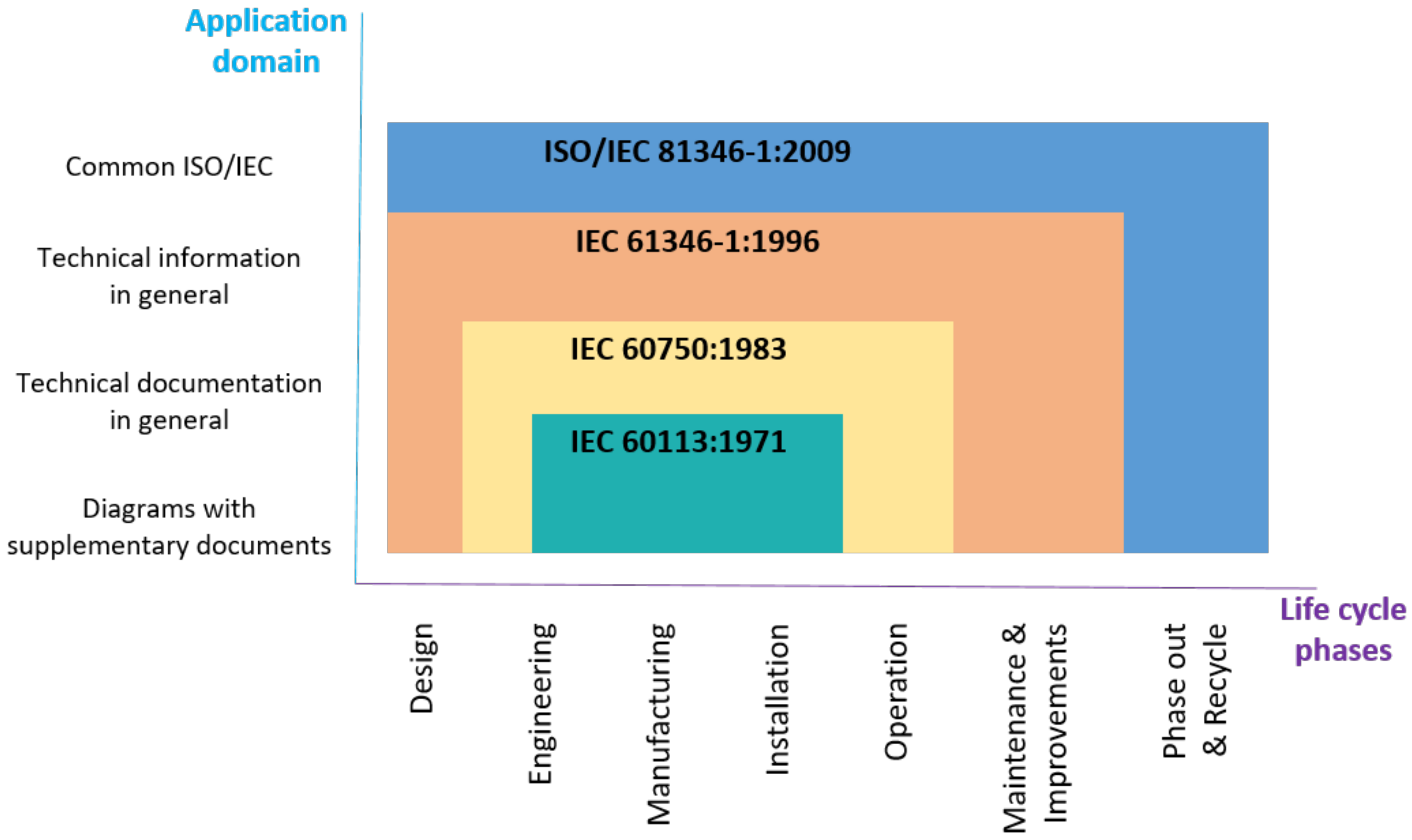
The standard ISO/IEC 81346 specifies that for studying objects and their relations, it may be helpful to look at them from different perspectives, highlighting various aspects of the objects and relations. This standard focuses on the three aspects of function, product, and location, although the design is intended to be capable of addressing other viewpoints, as well as to provide a guideline for the main engineering process phases that can be adopted to build the life cycle management models of objects to be manufactured [
35]. The standard is strongly related to previous standards developed to manage information through the product life cycle at the various engineering process phases, as discussed in [
35] and shown in
Figure 1.
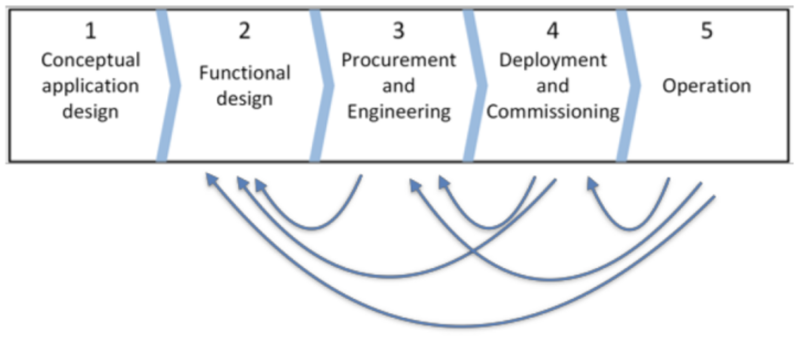
In
Figure 2, we show a representative picture of the main engineering process phases, which groups the main activities described in Clause B.2 of the ISO/IEC 81346 standard to define the development of one single object over its entire life cycle [
34]. This represents the baseline we use to construct the engineering process model presented in this paper.
The idea of using this standard as a reference for constructing an SOA-based framework has already been introduced in [
36] to be able to present all of the different types of objects and relations that are expected to be present in a future Internet of Things (IoT) or Industrial Internet of Things (IIoT) network in a useful engineering tool or set of tools. The concept of displaying different aspects of the same objects appears to be a useful solution.
An approach to the multistakeholder management of the life cycle has been proposed with collaborative product development [
37]. Nevertheless, this approach and other models, such as RAMI 4.0 and IEC81346, present different limitations in the coverage of EP phases, which, e.g., are limited only to the initial phases of the EP (typically functional design, development, and partial deployment) and do not cover commissioning, operation and management, maintenance, retirement, etc.
The ontology that we propose covers the entire EP and allows us to describe the complexity of an extensive system or SoS (e.g., a manufacturing plant), the role of the system constituent components and their relations (e.g., the plant machines and their role in the production process), and provides a basic common understanding of the system layout (e.g., the manufacturing plant). Moreover, the advantage of using an ontology is the possibility of sharing a knowledge base that improves the interoperability between different digitalisation and automation solutions, adopted by different stakeholders, with various roles in the IoT value chain, guided by a variety of interests, objectives, etc.
Currently, a critical necessity that characterises the Industry 4.0 paradigm is the digitalisation of highly interconnected processes that share valuable information for improving efficiency and increasing the flexibility of production systems [
38]. However, from this perspective, a new dimension emerges because the Industry 4.0 paradigm foresees the aggregation of stakeholders in ecosystems (e.g., a factory, an airport, and a transportation system), and this type of aggregation requires data sharing among different engineering processes and phases with their specific automation levels and different stakeholders, which are typically geographically distributed [
39]. Sharing these data enables the optimisation of productivity, raw material yield, energy and environmental footprint, operational and production costs, etc., which is the basic motivation for automation.
Several reference architectures and models have been conceived to improve the digitalisation level of manufacturing by combining concepts [
40], methodologies, and technologies taken from the IoT [
41], cyber-physical systems (CPSs) [
42,
43], cloud computing [
44,
45], big data analytics (BDA) [
46], and information and communications technology (ICT) [
47]. Some examples are the smart manufacturing ecosystem developed by NIST [
48], the industrial internet reference architecture (IIRA) [
49], the IBM Industry 4.0 Architecture [
50], and the reference architecture model industries 4.0 (RAMI 4.0), one of the most eminent emerging architectures [
16] that intends to drive the manufacturing industry in the direction of a more connected and integrated development model for EP automation [
51]. However, according to the shortfall analysis conducted by Moghaddam et al. [
52], these new reference architectures lack the ability to address some of the key enabling factors for Industry 4.0, such as service-oriented solutions and SoS that characterise modern and future industrial factories and production systems.
3. A SOA-Based Engineering Process Model
The service-oriented paradigm is central to the Arrowhead-EP, which is based on a service-oriented architecture (SOA), as it improves the interoperability of tool-chains and tools, simplifying their integration and automation, while improving the cooperation between the stakeholders involved in the product value chain. The adoption of the Arrowhead-EP model in a real EP is supported by the Eclipse Arrowhead framework (EAf), a service-oriented framework conceived to build SoS-oriented automation and digitalisation solutions [
53,
54].
The design of the new EP (the “Arrowhead-EP”) and its ontology started from these studies and from the gap analysis proposed in [
55], where the authors identified the need to define an EP model that can natively support both EP digitalisation and automation while improving EP interoperability, efficiency, flexibility, and reconfigurability across different vertical domains and related value chains.
Moreover, we extend the model with a complementary ontology defined to provide information about the product value chain, highlighting the cooperation and partnerships between stakeholders, the interactions between the phases of the Arrowhead-EP they adopt for product life cycle management, the EP automation level, engineering costs, etc. The simple, expressive, and straightforward representation generated from this model has been called the VCEP map.
3.1. The Arrowhead-EP Model
To meet the flexibility and automation levels required by Industry 4.0, the usage of IoT-based and SoS-based solutions represents an adequate approach to support the digitalisation of modern manufacturing facilities. However, technology is not enough, because even the engineering process must ensure the same levels of flexibility and automation across all phases of the product life cycle. For this reason, the rigidity of today’s approaches to automation, based on standards, such as the ISA-95 architecture [
56], represents a substantial limiting factor. More recent standards, such as RAMI 4.0 and IIRA, attempt to address the issue of engineering process flexibility but do not support it when moving from pure automation to the automation of the digitalisation process.
RAMI 4.0, for example, proposes managing this complexity by addressing it from three different perspectives (three dimensions of the problem space): (i) business, (ii) systems and components, and (iii) life cycles. The RAMI 4.0 reference model does not elaborate on how the parts within this convoluted solution space are interconnected and interact. It does not consider different stakeholders, who sometimes might have conflicting interests. In other words, it is not clear how the new generation standards can implement a data-driven architecture (Digital Thread) that links together information generated from across the product life cycle [
28].
In this work, we decompose and remodel the engineering process with the aim of introducing a service-oriented solution intended to efficiently, flexibly, and effectively manage the three assets addressed by RAMI 4.0 and extend the model with the capability to support some concepts of collaborative product development.
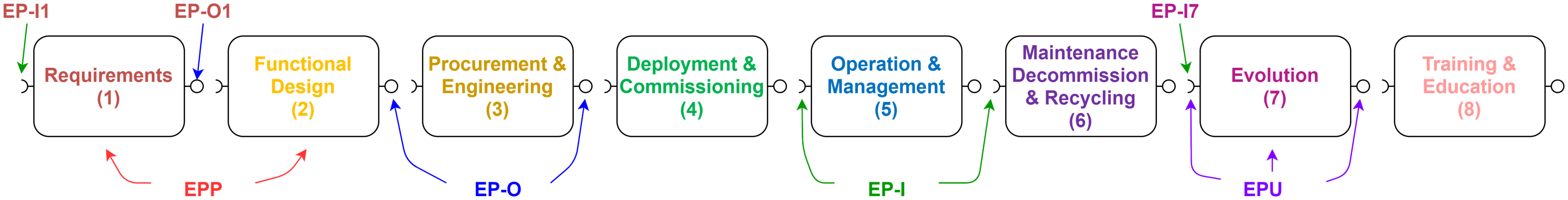
We develop a model to enable the analysis of all the phases in a multistakeholder engineering process. Focusing on a single stakeholder, the EP is partitioned into eight engineering process phases (EPPs), as shown in
Figure 3. Tool chains and tools developed for building the use case are associated with the specific EPPs where they are used. The ontology of a specific EP also reveals how EPPs, tool-chains, and tools interact, even between different stakeholders. With this approach, for example, it is possible to assign a CAD tool to the design phase of the EP of a car manufacturer, link it to the engineering phase of the same EP, and connect it to the requirement phase of the EP of a supplier that provides the specification of the components that are mounted in the car.
We identify six main objectives that the EP should have to satisfy the needs of Industry 4.0 in the life cycle management of smart production:
The extension from design time to run time engineering, i.e., the life cycle continuous engineering.
The shift from single stakeholders to multiple stakeholders integrated EP automation and digitalisation.
The capability to handle a substantially increased number of I/O due to much more fine-grained automation.
The inclusion of digital education and training activities as an integral part of EP.
The reduction of engineering costs obtained through the full digitalisation and management of the system life cycle.
The adoption of a service-oriented framework, native tool-chains/tools and legacy tools adapters to simplify, encourage, and promote the use of the new Arrowhead-EP model.
As the first step to reach these objectives, we propose extending the current automation engineering standard IEC 81346 [
34] by addressing the common challenges of modern industry and supporting the sustainability of the engineering and manufacturing processes. IEC 81346 does not consider EP phases that are key for Industry 4.0 and does not support feedback between phase and phase reiteration. To avoid these limitations and solve the issues identified in the gap analysis proposed in [
55], we add three supplementary phases to the five already present in the original IEC 81346-based EP (
Figure 2), and we introduce the possibility of reiterating phases and managing feedback. In the new Arrowhead engineering process (Arrowhead-EP, see
Figure 3) we add the engineering phases of
Maintenance, Decommissioning, and Recycling,
Evolution, and
Training and Education, thus attempting to capture the necessities of continuous engineering during system maintenance, future system evolution, decommissioning and retirement of the system at the end of life, and ensuring educational and professional training support across the entire system’s life cycle.
The possibility of modelling and controlling these new phases of the EP has a positive impact on the end user in terms of: (i) a faster return on investments; (ii) potential reduction of costs for maintenance due to the efficiency of continuous engineering, including validation, deployment, decommissioning, and retirement; (iii) potential reduction of costs for bug fixes, updates, and new releases of the system (continuous evolution); and (iv) an improved level of sustainability and reduced environmental footprint.
Moreover, we enrich the EP model with a complementary one called the value chain and engineering process map (VCEP-map) to represent the entire value chain associated with the specific vertical use case. The model maps the various system components with the stakeholders that design, develop, and operate them, and with the respective tools and tool chains.
3.2. The Eight Arrowhead Engineering Process Phases
We designed the Arrowhead-EP (
Figure 3) as a flexible solution to support the intertwined EPs of different use cases that characterise the industry domain. The eight phases composing the Arrowhead-EP are described as follows:
The Requirements elicitation phase consists of identifying the system requirements from users, customers, and other stakeholders. The output of this phase is typically the list of system requirements.
The Functional design phase consists of adopting the functional design paradigm to simplify the system design. A functional design assures that each modular part of the system has a precise role and performs that role correctly together with the other parts. Functionally designed modules tend to have low coupling. The output of this phase is typically a model or an architecture. Depending on the type of project, the output of this phase can also be a cyber-physical system model and/or a computer simulation.
The Procurement and Engineering phases proceed in parallel and are continuously interacting. The procurement phase consists of finding and agreeing to terms and acquiring the goods, services, or works required to engineer the system and construct or manufacture it from an external source. This phase is used to ensure that the buyer receives goods, services, or works at the best possible price when aspects, such as quality, quantity, time, and location, are compared. The Engineering phase, in turn, includes the design, development, and testing of the system, prototype generation, and after some iterations, the final version of the system (that will be Deployed and Commissioned). Considering the concept of feedback, engineering teams are also responsible for understanding the causes of the malfunctioning identified during the Operation/Maintenance phases and implementing the improvements determined during the Evolution phase.
The Deployment and Commissioning are sequential phases intended to prepare the system for operation. The deployment consists of the installation and integration of the system in a laboratory for testing and debugging purposes or in the final operative environment and includes the preliminary verification and validation of the system. Commissioning is the process of ensuring that the system is designed, installed, tested, operated, and maintained according to the operational requirements of the owner or the final client. Commissioning may be applied to new projects but also to existing systems subject to renovation, updates (e.g., for maintenance purposes), or expansion (see Evolution phase).
The Operations and Management consists of operating and managing the system according to the operational specification and requirements of the owner or the final client. From a temporal perspective, this is generally the longest phase in the system life cycle. In this phase, the system is also monitored remotely to acquire information about its behaviours during operations. This information is aggregated and dispatched to the Maintenance and Evolution phases but, if needed, also to other stakeholders in the system value chain for further analysis and activities, depending on their role.
The Maintenance, Commissioning, and Recycling phase consists of identifying and establishing the requirements and tasks to be accomplished to achieve, restore, and maintain the operational capability of the system across the entire life cycle. The Maintenance process must be executed concurrently with the operations process. Maintenance addresses bug fixes and minor enhancements, as well as minor adaptations to the standards, new features, software updates, and troubleshooting. In contrast, considerable changes in the system are identified and planned in the Evolution phase. In this phase, we also consider decommissioning the system at the end of its life and its responsible recycling to reduce the impact on the environment.
The Evolution phase attempts to address the inability to predict how a priori user requirements, market, and technology trends will evolve. The role of this phase is to monitor these aspects and identify and plan substanial changes in the future version of the system, including the system’s end-of-life. This phase must also ensure the continuous improvement of the system, always respecting the user requirements efficiently, reliably, and flexibly.
The Training and Education phase includes all the educational and professional training activities required by the engineering process across the entire system’s life cycle. This phase is responsible for the development of instruction and installation manuals, demonstrators, formative courses, and other learning material intended for a large audience that spans from engineering teams to end-users.
Other processes linked to the system life cycle, such as production, marketing, or sales, that are not directly related to the EP can eventually be represented as black boxes connected and interacting with the Arrowhead-EP. Links between the phases represent the data sharing between different teams for implementing various tasks, such as verification and validation activities, which, depending on the type of project, can be performed throughout the whole life cycle.
Here, in the description of the phases, we report a representative but not exhaustive list of activities that can be performed in each EP phase because we aim to provide a flexible EP model that is customisable for supporting the life cycle management of products and services with different needs and requirements.
The Arrowhead-EP described in this section has been modelled with an ontology and, within the Arrowhead Tools project, as having been used to defining the structure and the interaction between stakeholders in 33 different use cases using the
Eclipse Arrowhead framework, a service-oriented solution to manage and automate EPs and systems (see, e.g., Kozma et al. [
57]).
3.3. The Arrowhead-EP Concepts and Rules
We designed the Arrowhead-EP ontology to manage the complexity of the engineering process of Industry 4.0 use cases developed with an SoS paradigm. The ontology was conceived to track the interactions between the engineering process’s phases, tool chains, and related tools, especially considering the EPs adopted in the multistakeholder value chains.
The structure of the Arrowhead-EP model (
Figure 3) is based on
Engineering Process Units (EPUs), which are classified as follows: (i)
Engineering Process Phase (EPP), the eight phases described in the previous section; (ii)
Engineering Process Interface (EPI), which represents both the input (
EP-I[n]) and the output (
EP-O[n]) connections between the internal Arrowhead-EPPs and the external phases of other EPs adopted by different stakeholders involved in the system value chain. Moreover, we introduce the
Engineering Process Connection (EPC), which is an enumeration system adopted to assign a unique identifier to each EPI connection (a pair of interfaces). Depending on the nature of the EPI connection, specific agreements between stakeholders define who the stakeholder is responsible for when implementing the connection. In
Figure 3,
EP-O1 is an EPU that represents an output of the
Requirements EPP, while
EP-I7 EPU represents an input for the
Evolution phase. To enumerate the multiple EP-I/EP-O of a single EPP, we adopt the following rule: in the case of multiple EP-I, we begin by assigning a letter to each interface in clockwise order, starting from the input on the bottom left; in the case of multiple EP-O, we start the enumeration from the output of the EPP placed on the right-top side of the block. The Arrowhead-EP ontology also introduces the
Engineering Process Mapping (EPM) designed to identify the links between the tools and one or more EPUs.
The Arrowhead-EP of an IoT- or an SoS-based use case can be designed by connecting the EPPs in a custom flow graph, following the specific sequence of phases of the EP adopted in the use case and without necessarily adopting the sequential order illustrated in
Figure 3.
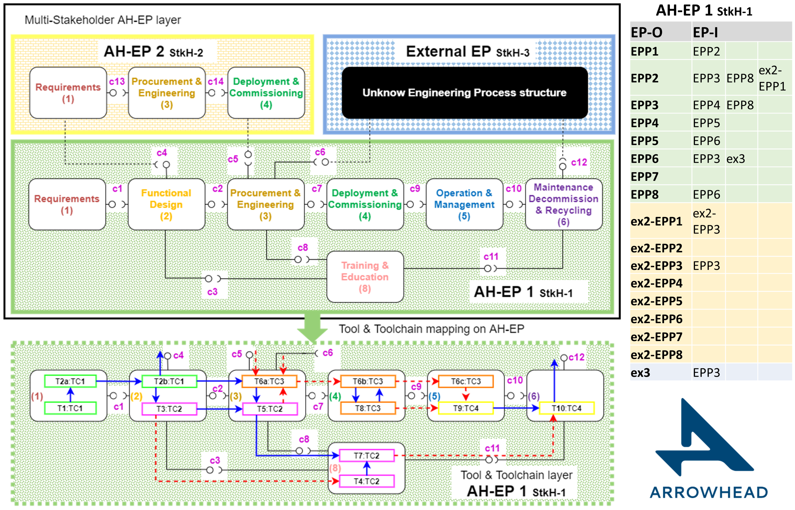
Figure 4 provides an example of a use case where two Arrowhead-EPs and an unknown EP adopted by three different stakeholders (StkHs) are connected and cooperate to design, develop, and operate a system. The dashed lines represent external EP connections between different Arrowhead-EPs and/or unknown EPs. In this example, Arrowhead-EP StkH-1 is the main EP that adopts seven of the eight Arrowhead-EP phases (the
Evolution phase is not used) and is connected with two external EPs: the Arrowhead-EP2 from stakeholder 2 and the External EP from stakeholder 3. Arrowhead-EP 2 is composed of three EPPs, where two (EPP1 and EPP4) are externally connected with EPP2 and EPP3 of Arrowhead-EP 1, respectively. The External EP, represented as a black box because the internal structure is unknown, receives inputs from EPP6 of Arrowhead-EP 1 and provides inputs in EPP3. It is the responsibility of the stakeholder adopting a specific EP to implement and validate the interfaces and connections belonging to the perimeter of the adopted EP (represented as coloured borders in the
Figure 4 example). Additionally, in the example, stakeholder 1 (StkH-1) is responsible for implementing and validating all the connections enumerated from
c1 to
c12, while StkH-2 is responsible for
c13 and
c14.
One important advantage of the Arrowhead-EP model is that the structure of the interconnections between the phases and stakeholders can change over time, following the evolution of the various system versions to be designed, developed, and operated. The adoption of a service-oriented approach facilitates the evolution of the Arrowhead-EP in terms of stakeholders, technologies, system components, tool chains and tools. Since the service interfaces hide the details of the elements that compose the EP, the approach simplifies their update and extension with new stakeholders, tool chains, and tools and limits the impact of changes on the logic driving the EP.
To represent the connection graph of the EPPs, we adopt a standardised tabular format originally designed for representing direct graphs (see table in
Figure 4). Focusing on a specific stakeholder, the structure of the main Arrowhead-EP is represented by the first eight rows. The first column contains the EPP name (or the relative number), and in the second column, the table reports the EPPs receiving information from the EPP indicated in the first column. In the case of interactions with an
external stakeholder adopting an unknown EP or an EP that does not follow the Arrowhead-EP model, the external phases can be listed starting from row nine and adding the
“ex-” label to the external components and to the external EPP name.
At the bottom part of
Figure 4, we propose a representation of the tool-chain and the tools adopted in the Arrowhead-EP. Each tool used to analyse and elaborate on the information required for system life cycle management is fully or partially contained in one of the EPPs. In the figure, we show a hypothetical mapping of four tool chains on the seven EPPs used in the example use case describing the life cycle management of the system component designed, developed and operated by StkH-1. The first tool chain (TC) represented with green boxes is adopted in the
requirements and
functional design phases. The blue arrows represent the automatic flow of information between tool 1 (T1), tools 2a (T2a) and T2b. Then, T2b, mapped in phase 2, passes the output with an automatised procedure (blue arrows) to the first tool T3 of the tool-chain TC2 (pink boxes) and to the tool in the
Reirement phase of Arrowhead-EP 2 (not represented in the tool and tool-chain representation layer of the figure). T3 passes the information to T4 (located in phase 8) by using a manual procedure represented by the dashed red arrow through connection c3. In connection c2 (between phase 2 and phase 3), the outputs of T2b:TC1 and T3:TC2 are passed to T6a:TC3 and T5:TC2 using automatic procedures. In phase 3, T6a:TC3 (which is the first part of tool 6 belonging to TC3) transmits information with an automatised procedure to T5:TC2 and receives feedback with a manual system. Moreover, T6a:TC3 manually transmits and receives information from other stakeholder owners of the other EPs before manually sending the output to T6b:TC3 located in phase 4. Eventually, we have the rest of TC3 on phase 5 and TC4 mapped on phases 5 and 6.
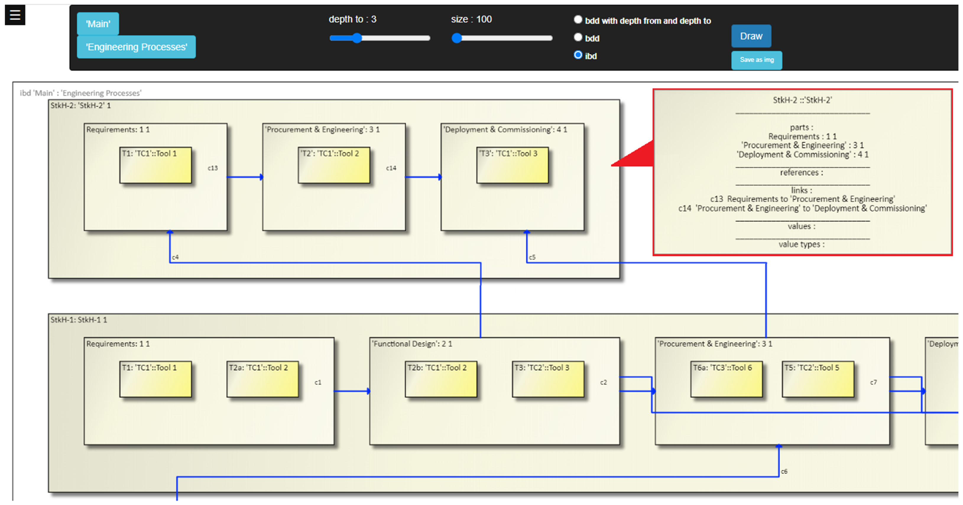
In
Figure 5, we report the output of a visualisation tool (in beta version) that we develop for representing EPs designed with the Arrowhead-EP ontology. The figure refers to the same example proposed in
Figure 4. This tool elaborates an EP described in SySML 2 and, depending on the configuration settings, can generate multiple levels of connections with increasing granularity that go from the Arrowhead-EP level to the tool-chains and tools levels. Focusing on a specific system, the graphical interface allows the definition of the multistakeholder Arrowhead-EP adopted for the life-cycle management of that system.
3.4. The VCEP-Map Ontology
The Arrowhead-EP model is further extended with the Value Chain Engineering Process map (VCEP-map) to better describe and visualise the entire value chain associated with the system. The VCEP map allows us to highlight the value chain dynamics, the relations between the engineering phases, the tool chains and tools, the relations and synergies between the stakeholders, and the components of the system. The VCEP map contains complementary information that, when combined with the Arrowhead-EP ontology, provides a 360-degree view of the use case and the associated value chain across the entire system life cycle.
A VCEP map is structured in a tabular format, where each stakeholder is identified by a specific colour and a unique ID. The columns represent the Arrowhead-EP phases (i.e., the system life cycle), and the rows contain a specific aspect of the value chain.
Figure 6 illustrates an example of the VCEP map associated with the multistakeholder Arrowhead-EP represented in
Figure 4. The example describes seven different aspects of the value chain. In the first row, we have the eight engineering phases of the Arrowhead-EP model grouped in one line (i.e., all the edges connecting the different phases are hidden, and the phases from the different stakeholders are grouped). Then, from the second row on, we represent value chain information useful for characterising and evaluating the complexity of the different activities implemented during the life cycle of the developed system. In the second row, labelled
Value and Supply-Chain, we map the stakeholders on the Arrowhead-EPPs where they are involved. In the third row, using the stakeholders’ colours, we map the
Tool-Chains (graphically represented with bars having the same colours of the StkH bars) adopted by each stakeholder on the Arrowhead-EPPs, and in the next row, the
Tool-Chains Automation Level is expressed as a percentage. Then, in row
System Components Tool-Chains view, we show where each component of the system is mapped on the Arrowhead-EPPs and on the tool-chains that are used during its life cycle. In the following row named the
System Components StkH view, we aggregate information provided in the
System Components Tool-Chains view for proposing a synthetic view of the stakeholders that are responsible for designing, developing and operating each system component. In the
System Integration row, we highlight the stakeholders and the tool chain used to integrate the system components to build the final system of systems. In the last row, we report the estimated normalised costs of each engineering phase that every stakeholder expects during the life cycle of the system, thus having a broad view of the overall cost distribution. Obviously, some of the information for StkH-3 is missing because the EP information from this stakeholder is not available (black box).
In this example, we demonstrate that the VCEP map can provide supplementary information not explicitly available in the Arrowhead-EP model. The VCEP map introduces the opportunity to explore at a glance which tool chain is adopted to design, develop, and operate a specific system component, the role of the stakeholders involved in the life cycle of the component, the stakeholder coverage of the value chain, the tool chain coverage of the value chain, and the normalised costs.
The VCEP map can be further extended by adding new rows to show how supplementary characteristics of the value chain relate to the information already present in the map. For example, a new row can represent the level of automation of tools in the various phases of the Arrowhead-EP, or a row can focus on the adopted standards or on the main objectives reached by the different stakeholders in the Arrowhead-EPPs.
Information represented in the rows is not fixed, and the table can also be customised considering the targeted user. For example, costs can be provided to the internal team of the same stakeholder but can be removed in the public version of the VCEP map to be shared with third parties or even with potential competitors.
The VCEP map improves the flexibility of the model, enriching it with other information, such as those addressed in the layers of the RAMI model and orthogonal to the life cycle dimension. RAMI 4.0 is difficult to visualise due to the complexity of its 3D representation, while the linearity and simplicity of the VCEP-map considerably improve the readability of the model, with a potential impact on the Arrowhead-EP efficiency and costs.
An example of a VCEP map for a real use case is proposed in the results
Section 4.
3.5. The Arrowhead-EP Model and the Execution of a Real EP
The model is implemented with an ontology that, instantiated for a specific Arrowhead-EP, provides all the details related to the EP coverage, adopted tool-chains and tools, connections between EPPs, tool-chains, and tool dependencies. The model is also supported by a tabular format that simplifies the visualisation of the Arrowhead-EP and, according to the ontology described in
Section 3.3, can be encoded in a standard way by adopting a simple table or in a more structured way using specific modelling languages. The adoption of system modelling languages, such as SySML, potentially makes complex multistakeholder EPs simpler to model, control, and extend, while simplifying their practical management, and improves the efficiency, flexibility, and scalability of the modelling process. Moreover, system modelling languages promote the adoption of machine-supported engineering and autonomous engineering, which play a key role in the future evolution of engineering process automation.
Starting from the ontology of a specific Arrowhead-EP, a service-oriented framework allows the management of the Arrowhead-EP and facilitates its automation. For this purpose, we select the
Eclipse Arrowhead framework (EAf) [
58], which, with a service-oriented architecture (focused on microservice support), simplifies the creation and management of the links and dependencies between tool-chains/tools, provides security and authentication support, and facilitates the integration, automation and practical management of the Arrowhead-EP in real use cases.
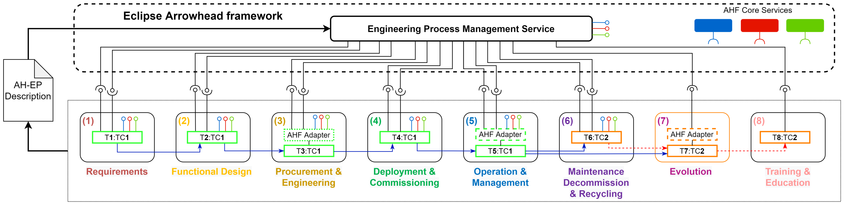
In the
Eclipse Arrowhead framework, the Engineering Process Management System (EPMS) is the new component in charge of managing the Arrowhead-EP. The EPMS (
Figure 7) acts as a scheduler and orchestrator of the EP and is required to monitor the ongoing activities to ensure that the dependencies between phases, stakeholders, tool-chains and tools are respected. Moreover, EPMS is responsible for scheduling and controlling sequential and concurrent EP activities and managing tool inputs and outputs. Due to the SOA/microservice architecture of the
Eclipse Arrowhead framework, the EPMS can be implemented by adopting a scheduler already available on the market or extending some
Eclipse Arrowhead framework (EAf) services currently under development [
59]. The EPMS will be the subject of future works.
To provide these functionalities, the EPMS needs an
Arrowhead-EP description (
Figure 5), which is the use case engineering process schema designed with the ontology of a specific Arrowhead-EP and with the related VCEP-Map.
The EPMS models the EPPs as services. Each EPP generating outputs is represented by a service that publishes data in the
Eclipse Arrowhead framework, while every EPP requiring an input is represented by a service that consumes data from one or more
EAf services published by other EPPs and belongs to the same Arrowhead-EP or to other EPs in the case of a multistakeholder use case. The EPP services require three parameters: the ID of the Arrowhead-EP, the ID of the tool producing and consuming data/EP-metadata, and the produced and consumed data/EP-metadata (or a pointer to it). Tools composing the tool chains call the services to provide and consume information. Tools not supporting the
Eclipse Arrowhead framework, such as proprietary or legacy tools that cannot be upgraded with
EAf support, can interact with
EAf services through a specific
EAf Adapter (e.g., phases 3-5-7 in
Figure 5). On the one hand, the
EAf Adapter interfaces directly with the tool native interface to obtain or provide data; on the other hand, it calls the
EAf services simulating an
EAf native tool. Eventually, tools can provide
EAf services natively or through an adapter, which allows the EPMS to control them.
Figure 7 illustrates an example of an Arrowhead-EP composed of two tool-chains managed by the EPMS.
4. The Arrowhead-EP of a Real Use Case
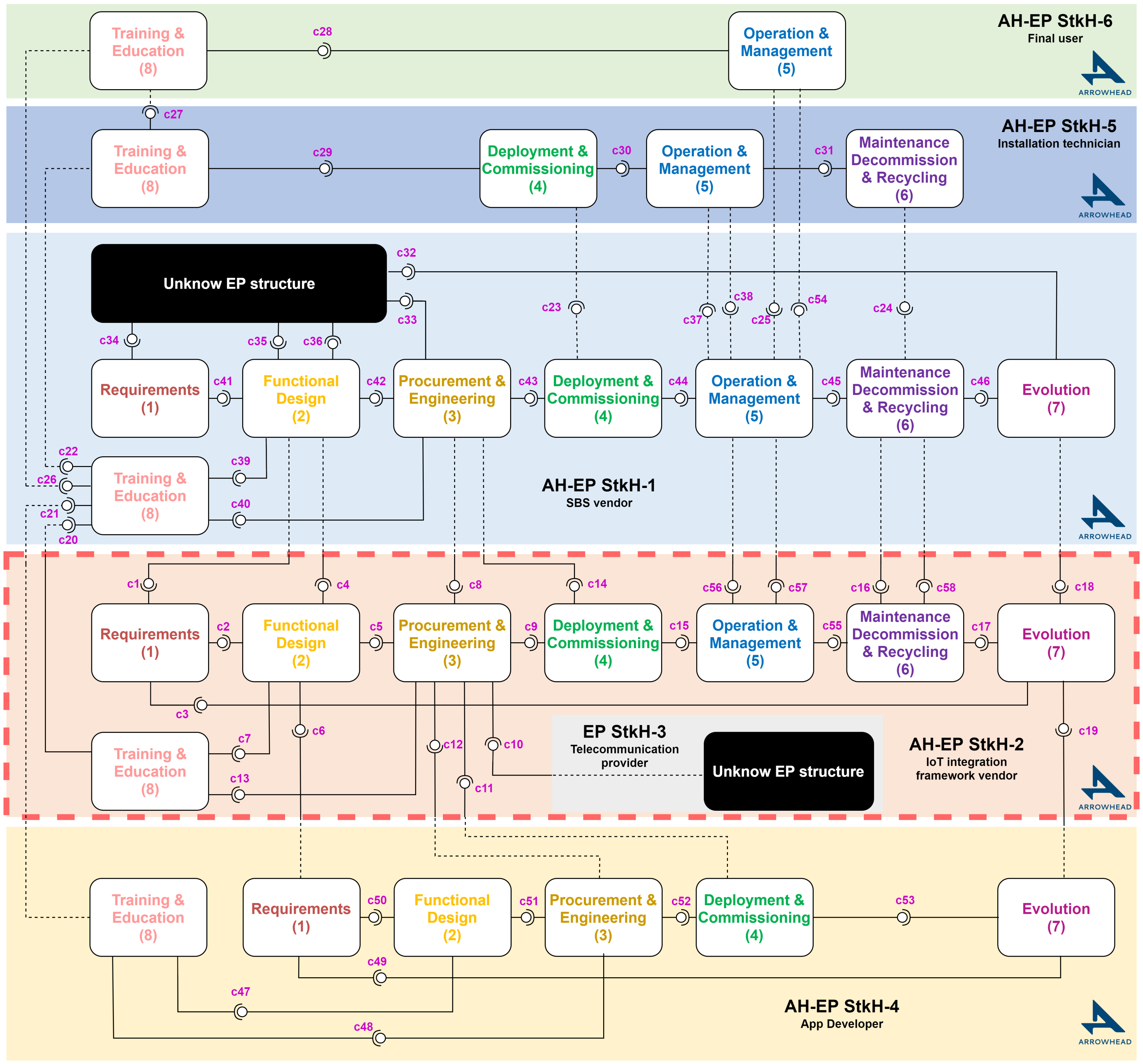
In this section, we present a smart heating system inspired by a real business case as an example to demonstrate the advantages of adopting the Arrowhead Engineering Process model in a real SoS application. Smart boilers are becoming very popular for the advanced features offered to the final user for improved safety, the reduced costs, and the limited environmental footprint of this category of appliances. The digitalisation of a heating system is a complex process, implying the life cycle management of a complex SoS, with a value chain composed of several stakeholders, each adopting different EPs to design, develop, and operate the components of the system.
A smart boiler system (SBS) is an end-to-end solution for the consumer market, intended to extend a standard boiler for home usage with connectivity and smart functionalities; it is then integrated into an IoT infrastructure and provides added-value services for the manufacturer, installer, and final user. For the manufacturer, the SBS, and the associated EP, simplify, improve, and optimise the management of a fleet of boilers, improve the quality of the product, reduce maintenance costs, and increase the return on investment. It also simplifies the everyday activities of maintenance operators and improves the quality and safety of their job. For the final user, SBS improves boiler safety through continuous remote monitoring by qualified personnel, and it increases the comfort level while reducing energy consumption and the carbon footprint. Thus, SBS is a relevant example to illustrate the complex value chain that supports an apparently simple consumer application.
4.1. The Use Case Described with the Arrowhead-EP Model
Figure 8 illustrates the Arrowhead-EP model of the entire EP adopted by the stakeholders involved in the life cycle management of the SBS. The SBS vendor (StkH-1) leads the value chain and is involved in every phase of the EP, across the entire life cycle of the product, from early design to manufacturing and final retirement. In addition, the vendor of the IoT integration framework (StkH-2) leads the digitalisation of this appliance. The telecommunication provider (StkH-3) is a service provider, while the app developer (StkH-4), the installation technician (StkH-5), and the final user (StkH-6) utilise the services and functionalities offered by the SBS at different levels depending on their roles.
StkH-1 designs and develops the electromechanical parts of the boiler and creates the requirements to be provided to StkH-2 (connection c1), which will develop the embedded control unit (ECU) that allows the boiler’s digitalisation. StkH-1 is also involved in the Deployment and Commissioning of the SBS and in its remote monitoring during Operations and Management. StkH-1 exploits the information collected from the SBS fleet (c25) to ensure safe operation, plan maintenance activities, improve the product, and guarantee its evolution. Eventually, StkH-1 is involved in the professional training of maintenance operators and the production of documentation for the other partners of the value chain, C22 and C26, and the final users.
The IoT platform vendor (StkH-2) designs and develops the SBS ECU, the IoT framework running on the edge in the ECU, and its counterpart, the IoT integration platform that manages the entire fleet of SBSs. The IoT framework and integration platform provide services and APIs that allow the development of the application’s business logic and integration at the enterprise level. Thus, the IT department of the smart boiler manufacturer (StkH-1) can integrate the fleet of smart boilers in its organisational processes, providing remote control, preventive and predictive maintenance, and collecting precious information about the product life cycle.
The application developer (StkH4) adopts these services and APIs to develop final user applications intended for the maintenance operator and the consumer.
This example demonstrates that the Arrowhead-EP model is a good solution to easily and flexibly describe the complexity of the management of an SoS product life cycle. The Arrowhead-EP model illustrates the dynamics of the EP, the relations and the synergies between the stakeholders, and their involvement in the EPPs of different EPs, even when some of them have to be considered “black boxes”, because the stakeholder does not adopt the Arrowhead-EP due to the absence of an agreement between the stakeholders or due to intellectual property issues (see, e.g., the EP of StkH-3 and part of the EP of StkH-1).
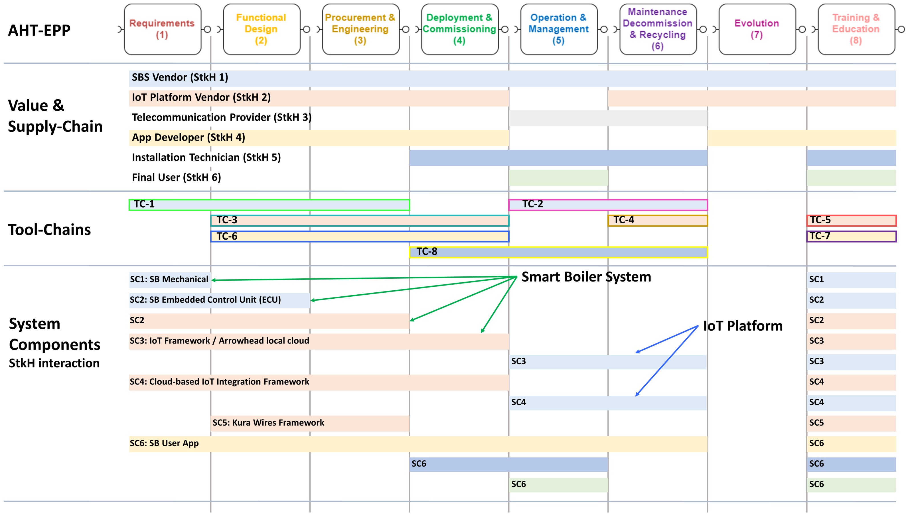
4.2. The Use Case Value Chain and Engineering Process Map
Figure 9 illustrates the value chain and engineering process map (VCEP map) of the SBS use case, a new approach to provide a complete overview of the value chain that supports the use case. As discussed in
Section 3, the VCEP-map is a simple and effective two-dimensional schema, describing the ecosystem of the stakeholders, technologies, design methods, and tools involved in the engineering process of the smart boiler and providing information about the EPs that are complementary to the Arrowhead-EP model. For each component of the SBS, the VCEP map specifies (i) which tool chain has been adopted for the engineering of the component and in the phases, (ii) which stakeholders have been involved and (iii) where phases of the smart boiler’s life cycle the components are used and by whom.
For example, the “Value and Supply-Chain” section of the map specifies that the SBS vendor (StkH1—light blue) is active in all the phases of the Arrowhead-EP and adopts two tool-chains (TC-1 and TC-2, see the “Tool-chains” section). These two tool chains are used in phases 1, 2, 3, and 5, 6 to design, develop, and operate the electromechanical parts of the SBS, integrate the SBS ECU in the boiler, and operate and manage the fleet of SBSs with the IoT framework and the IoT integration platform. Regarding the previous two components, the map also highlights the cooperation of StkH1 and StkH2 (the IoT platform vendor). In the “System Components” section, the map specifies that the IoT framework (SC3) is a component designed and developed by StkH2 but operated by StkH1, while the SB User App (SC6) is designed, developed, deployed, and maintained by the app developer (StkH4) and is used during operations by the maintenance operator (StkH5) and by the final user (StkH6). The map also clearly highlights that the evolution phase is not automated by any tool, although the related activities are addressed by some of the stakeholders.
The SBS use case is a relevant SoS example that is developed, designed, and operated using an Industry 4.0 EP. This demonstrates that the combination of the Arrowhead-EP model and the VCEP-map provides a rich, detailed, easy-to-understand, and complete description of the value chain and life cycle of the final product.
5. Properties and Benefits of the Arrowhead-EP and the VCEP-Map
In
Section 2,
Section 3 and
Section 4, we detail the Arrowhead-EP model and the ontology for enabling the digitalised management of the life cycle of complex industrial multistakeholder use cases. This section discusses some of the notable advantages offered by the adoption of the Arrowhead-EP model and the VCEP-map in the Industry 4.0 domain.
The Arrowhead-EP model complemented by the VCEP map proposed in this paper addresses the six objectives (see
Section 3) that an EP should support to satisfy the needs of the life cycle management of an Industry 4.0-oriented solution. Thus, the Arrowhead-EP model, complemented by the VCEP map, is widely flexible and adaptable to support a large spectrum of heterogeneous vertical UCs, ranging from semiconductor engineering to mining, finance, construction industry, IoT, etc.
The Arrowhead-EP model allows feedback that provides inputs to previous phases of the EP and introduces a specific phase focused on
Evolution, intended to provide feedback for system bug fixes, updates, and future releases. This enables continuous engineering and extends the coverage of “design-time” phases, classically addressed by the EP to “run-time” phases across the entire system life cycle. Additionally, the structure of the EP can evolve over time because the service-oriented Arrowhead-EP allows adding, removing, and modifying phases, the interactions between them and the stakeholders, and the associated tool chains. This particular feature is also supported by the Eclipse Arrowhead framework, where, starting from the EPP description, each EPP becomes a service: adding, removing, and modifying an EPP requires only a new version of the implementation that, once loaded in the EPMS, is ready to be executed. Continuous engineering is enabled by the presence in the EP of a coherent flow that extends from the “Design-time” to the “Run-time” phases of the EP, covering the entire system life cycle. The design and the development phases include all the phases preceding the system deployment, such as requirements elicitation, conceptual design, architectural design, implementation and testing, and prototype development [
60]. “Run-time” phases cover the rest of the life cycle (the longest part from a temporal perspective), from system deployment and commissioning to standard operations, maintenance activities, identification of updates and future releases, until the system end of life, with retirement, decommissioning, and recycling, which is fundamental for the EU Green Deal objectives. Moreover, the presence of an
evolution phase and the possibility of creating feedback-based loops between EPPs is a fundamental enabling factor for continuous engineering.
The automation and digitalisation of the EP extends from single-stakeholder EPs to integrated multistakeholder EPs because the Arrowhead-EP model allows us to “connect” the phases of two or more different EPs adopted by different stakeholders through the service-based interfaces of the EPPs. The coherence of data managed by the EP and the intellectual property issues associated with data sharing, data processing, and the execution of a multistakeholder EP are ensured by the adoption of an integrated solution and by the privacy and security features provided by the Eclipse Arrowhead framework across the entire life cycle of the system. The engineering of complex multistakeholder systems, very frequent in the IIoT domain, is supported by the possibility of interfacing, integrating, and managing different EPs adopted by stakeholders to design, develop, and operate the system components.
The possibility of handling and automating an increased number of I/Os is guaranteed by the capability of the Arrowhead-EP to manage multiple I/O interfaces (i.e., services) for each EPP. The model is scalable since there is no limitation in terms of EPUs, which are simply and efficiently described in the ontology. The Arrowhead-EP model can be adopted recursively to describe the final system but also the components and subcomponents (both hardware and software) that, following the SoS paradigm, compose the system. Arrowhead-EP workflows can be defined at different abstraction levels, depending on the purpose of the workflow, the role of the people involved, the toolchains, and the tools.
The professional expertise and capabilities of the people involved in the EP represent a critical factor for engineering, and the Arrowhead-EP includes a specific phase focused on professional Training and Education, covering all the figures involved in the EP: analysts, engineers, technicians, specialised operators, maintenance operators, and even the final user.
The potential reduction in engineering costs is a direct consequence of a more automated and digitalised EP, which efficiently exploits modern IoT/SoS integration platforms, new tools, and integrated tool chains. Moreover, the engineering cost reduction potentially also originates from the improvement in the quality of the EP results indirectly because automation minimises the possibility of human errors. The Eclipse Arrowhead framework plays a fundamental role in automation managing EP execution. The Arrowhead-EP model, supported by the Eclipse Arrowhead framework, allows an efficient, secure, and simple sharing of EP information for all stakeholders involved in the system value chain and starting from the early stages of the EP. This has a potential positive impact on the engineering cost [
61], confirming the strong innovation potential of the automation and digitalisation of the Arrowhead-EP.
The approach proposed in this paper is supported by an existing and stable SOA/microservice framework, the Eclipse Arrowhead framework, which provides an architecture, appropriate tools and services required for the efficient digitalisation and automation of complex multistakeholder EPs.
In the following, we list a summary of the major properties of the Arrowehad-EP and the VCEP-map when integrated into the Eclipse Arrowhead framework.
Information Feedforward and Feedback of information between engineering phases is supported.
Run-time engineering is enabled by the Evolution EPP and property 1.
The engineering process can integrate information from multiple stakeholders.
Each engineering process phase can produce or consume more than one service.
The model is scalable to any number of EPUs.
The Training and Education EPP provides education services to all other EPPs.
The automation of certain engineering tasks is supported, enabling the reduction of UC life cycle costs.
The EPs can be implemented by SOA/microservice-based implementation platforms.
Data security and privacy between stakeholders can be ensured through microservice AAA security.
Multiple use case EPs can be integrated through services.
The engineering workflow can be modelled at different abstraction levels.
6. Conclusions
The engineering process (EP) of a digital System of Systems (SoS) requires a change in perspective and approach to address the evolving requirements of the Industry 4.0 domain: flexibility and evolvability, an increased level of automation, multistakeholder management, full life cycle support, cost reduction, and environmental sustainability. Architectural models addressing the life cycle and the value chain, such as RAMI 4.0, are available, but are affected by scalability limitations and are difficult to adopt in real industrial use cases.
Therefore, in this paper, we present an enriched set of models, maps, and tools to simplify and make the modelling and execution of the engineering process of the Industry 4.0 use case more efficient and cost-effective. The proposed solution models and highlights a large amount of complementary information associated with the EP, including the phases composing the EP, the relations and the connections between them, the tool chains, the tools, the structure of the associated value chain, the stakeholders involved in system life cycle management, and their relationships.
Finally, we discuss how the Arrowhead-EP model can be used to manage the entire life cycle of the smart boiler use case, and we discuss the advantages of adopting this new EP model in a real vertical application. Thus, we address the main objectives identified in the literature gap analysis.
At the moment, we define the Arrowhead-EP and VCEP-map ontology for describing the EP of relevant industrial use cases, while future works will be aimed at integrating the proposed technologies in automatic working pipelines designed to manage the life cycle of products and services. A future solution will be based on the Eclipse Arrowhead framework, which provides the services and functionalities required to simply automate EP tools and tool-chains.


 ,
, 


