Article

Study of Crack Growth of Transparent Materials Subjected to Laser Irradiation by Digital Holography

1
Department of Precision Mechanical Engineering, Shanghai University, Shanghai 200444, China
2
The Palace Museum, Beijing 100009, China
3
Department of Engineering Technology, Middle Tennessee State University, Murfreesboro, TN 37132, USA
4
Institute of Electronic Structure and Laser, Foundation for Research and Technology, Hellas, GR-700 13 Heraklion, Greece
*
Author to whom correspondence should be addressed.
Submission received: 5 July 2022 / Revised: 25 July 2022 / Accepted: 31 July 2022 / Published: 3 August 2022
(This article belongs to the Special Issue Holography, 3D Imaging and 3D Display Volume II)

Abstract

:
The crack growth of transparent materials after laser wavelength irradiation was studied. It is known that laser irradiation is used in many applications for the ablation of undesired material and/or coatings. The impact of laser irradiation on cracks was studied using the digital holography (DH) technique. Transparent samples were irradiated using near-ultraviolet, visible, near-infrared, and infrared light. The DH system is able to detect cracks and crack growth of the transparent samples irradiated by a range of laser wavelengths. Results also show that light with infrared to near-infrared wavelengths has a great effect on crack growth. High-resolution photomechanical effects of laser irradiation on material expansion or/and generation of defects due to specific wavelengths are also illustrated. The DH system with a multispectral laser has practical applications for laser cleaning of painted artworks.

1. Introduction

Materials are susceptible to cracking under accidental or artificially induced stress due to structural movement. Structural movements slowly but steadily affect the integration of materials and constructions, generating defects. Structural defects include detachments between multilayered surfaces, loss of material-producing material voids, and loss of continuity within the matrix of the material. Crack generation is a very common problem of materials resulting in weak construction and material degeneration. The parameters that affect crack growth are well studied [1,2,3,4,5,6,7]. Cracks lead to the fracture of a material. As such, it is important to establish a crack fracture model for the prevention of cracks and fractures. Frequently, finite element analysis is used for stress analysis of the material to model the dynamic expansion of cracks [8,9].
Through the study of crack initiation and development, it has been found that cracks are characterized by a “time window” [10]. The time window is the duration between the application of external stress or environmental changes and the generation of the first crack. The time window required for the consequent cracks is shortened and will decrease exponentially. As such, it is important to achieve early detection of cracks and provide intervention strategies for the cracks [11,12]. The growth of cracks is able to be predicted using deep learning methods [13]. Novel sensing technology is important to achieve early and precise crack detection.
Oil paintings represent a structure of stretched textiles on a rigid frame with adhesive, painting layers, and varnish [14]. It is crucial to protect the outermost protective layer of varnish to prevent irreversible damage (e.g., mildew, peeling of pigment layers) to the painting. Cracks of a painting are generated on the surface of the varnish layer due to multiple factors, including aging over time, external mechanical vibrations [14], gradients or drastic changes in humidity [15,16] and temperature [7,17], and chemical contamination. It is also known that laser cleaning, widely adopted for oil painting, is actually capable of generating cracks [18,19,20,21,22,23]. Furthermore, laser irradiation itself is also able to generate cracks [24,25,26,27]. Laser cleaning is a process for restoring the aesthetic of the painting through the photothermal, photochemical, and photomechanical effects [28,29]. The unwanted layer in paintings could be removed by laser of different wavelengths, including ultraviolet, visible, and infrared light [30]. A real-time monitoring system of short-term and long-term effects of laser cleaning could better explore which frequency bands of light may cause harm to achieve safe laser cleaning [31,32].
Deterioration of precious works of art cracking can result in loss of aesthetic appearance, depreciation of value, and destruction of irreplaceable cultural heritage and identity. Previous methods for crack detection have been proposed, including the nanoindentation technique [33] and the three-dimensional (3D) scanning technique [14]; however, measurement errors are common for nanoscale techniques [34,35], which may be caused by trace wear of the measurement including microscopic defects on the specimen surface, and slight changes in the experimental environment. Furthermore, such a technique cannot be performed in real-time, and is thus inefficient. In addition, 3D scanning technology also has limitations [36] in terms of accuracy and scale, which can be time-consuming. The application of digital holography in the field of high-precision inspection of transparent materials has been well established [37]. As a micro and nano-level detection technique, DH has been used to nondestructively detect the shape of cracks on the material surface in real-time [38]. Both the phase and intensity of the object could be numerically reconstructed by only one hologram. Hence, DH has a fast computational process that is faster than nanoindentation and 3D scanning techniques [39]. Digital holographic microscopy for cracking in transparent materials has also been successfully conducted by our team [40], showing that digital holography is suitable for crack detection in transparent materials. The fundamental principle of DH to detect crack growth is explained in Section 2.
Our research goal was to examine the cracks on the surface of oil paintings and their irradiation growth. We used dammar varnish as an experimental material [13], which plays a critical role in increasing the brightness of the image as well as in protecting the oil painting layer from cracking. In contrast to previous work, it only involves a 532 nm laser to both pump and probe cracks aiming to monitor the potential generation and growth of cracks on Dammar varnish [41]. In our research, a novel optical geometry with a multispectral pulsed laser to achieve both irradiation and crack detection using DH is designed (see Section 3). A new switching operation was used to select the pump irradiation path or the probe interference monitoring path.

2. Fundamental Principle

Digital holography records the amplitude and phase information of an object simultaneously. The complex amplitude distribution on the CCD plane is shown as follows:
H 1 x , y = O 1 x , y + R x , y 2 .
The complex amplitude distribution of the object light O 1 x , y = O 0 x , y exp j O 1 x , y and the reference light R x , y = R 0 exp j r x , y   , where O 0 x , y   , R 0 represent the intensity of object light and reference light, respectively; and 01 x , y   and r x , y   represent the phase of object light and reference light, respectively.
After being irradiated by laser, the crack underwent slight deformation. The intensity of the light wave reaching CCD remained unchanged, and only the phase distribution changed. In this case, the object light can be expressed as follows:
O 2 x , y = O 0 x , y exp j O 2 x , y  
if the reference light, R x , y , is a constant, the complex amplitude distribution will be   H 2 x , y = O 2 x , y + R x , y 2 .
The holograms H 1 x , y and H 2 x , y   are reconstructed through the reference light   R x , y . The reconstructed complex amplitude distribution is as follows:
U 1 x , y = R x , y H 1 x , y = R x , y R x , y 2 + O 1 x , y 2 + O 1 x , y R * x , y + R x , y O * x , y ,
U 2 x , y = R x , y H 2 x , y = R x , y R x , y 2 + O 2 x , y 2 + O 2 x , y R * x , y + R x , y O * x , y .  
the hologram can be reconstructed using the angular spectrum method with the transfer function T expressed as follow T = exp i 2 π d λ 1 λ f x 2 λ f y 2 .
Where   d   is the reconstruction distance; λ is the wavelength of the detected light source; and f x , f y are the coordinate expressions in the frequency domain. The initial phase O 1 x , y   is as follows:
O 1 x , y = tan 1 I m U 1 x , y / R e U 1 x , y .
Similarly, the phase O 2 x , y   of the sample after being irradiated by the laser is as follows:
O 2 x , y = tan 1 I m U 2 x , y / R e U 2 x , y .
To measure the growth distance of the crack, only the phase difference of the crack sample needs to be measured: Δ φ x , y = O 2 x , y O 1 x , y .
As the laser passes through the transparent material, the phase difference is correlated with the laser wavelength, the refractive index of the object, and the optical distance difference. The crack growth length is computed through the following equation: Δ l x , y = λ 2 π n · Δ φ x , y ,   where n is the refractive index of Dammar varnish, n = 1.48951.
In this experiment, the phase changes resulted from irradiation are obtained through unwrapping the phase of the holograms to extract the results of phase differences. Phase differences are used to measure the changes in phase growth, which is caused by the growth of the tip crack in varnish oil. By calculating the phase differences, the distance of the tip crack growth is obtained.

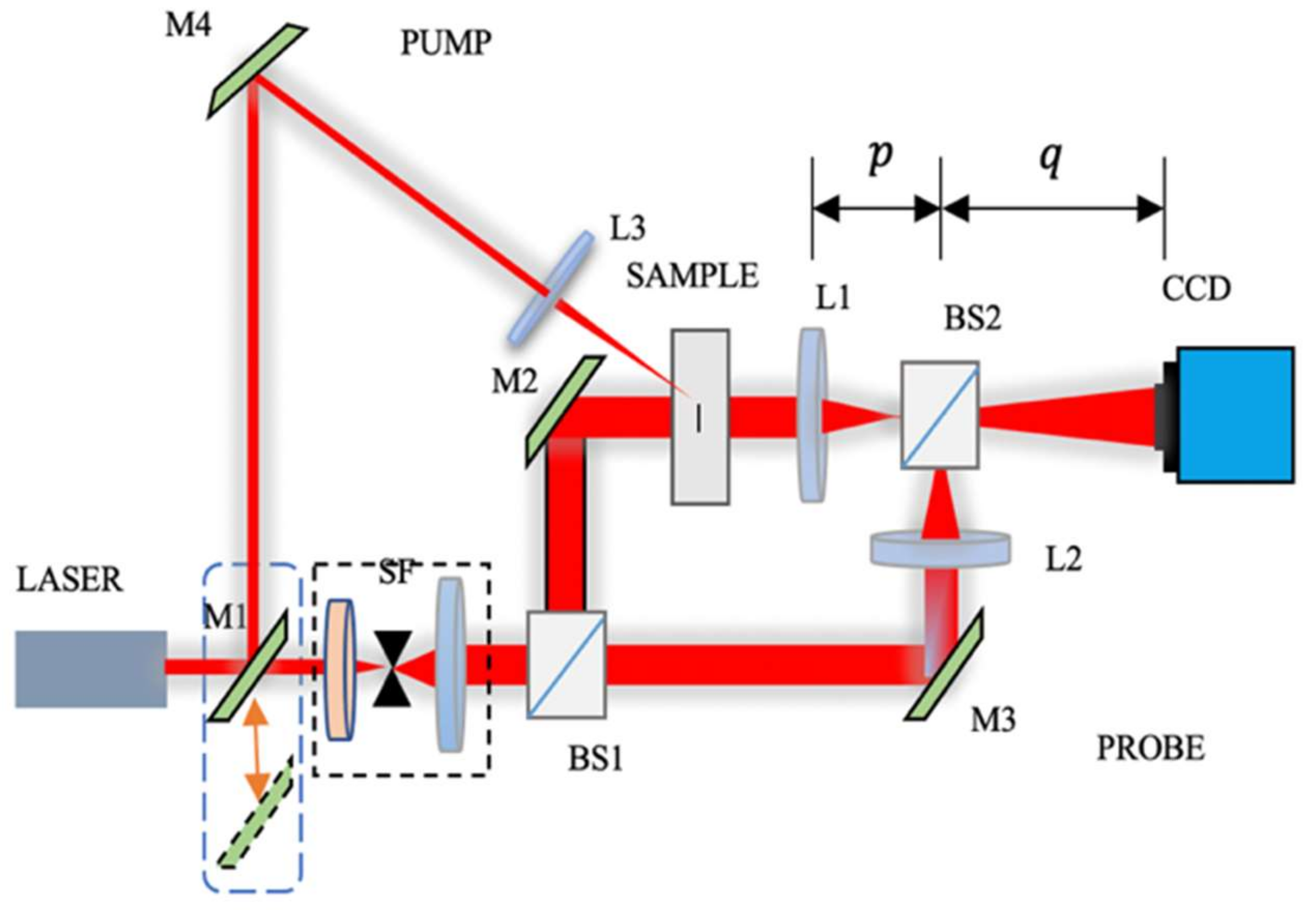
3. Experimental Setup

In this experiment, an SC-PRO multispectral pulsed laser as the light source was used. The output wavelength was adjusted from 430 nm to 1450 nm, and the working power was 8 W. The frequency adjustment range was 0.1–80 MHz. DHC-MER-500-7UM CCD pixel size 2.2   μ m   × 2.2 μ m ; a resolution of 1544(H) × 1944(V) was used to record the hologram. The calibration magnification of the digital holographic interference system was 1.976 [42].
The schematic diagram of the optical system is shown in Figure 1. It is a Mach-Zehnder off-axis holographic interference system and the wavelength of the light source is 633 nm. The systems have two major components: the pump and the probe. The reflective mirror M1 can move in a direction perpendicular to the optical axis and is used as a switch between the irradiation optical path and the optical detection path. As shown in Figure 1, when the mirror M1 is placed at the position represented by the solid line, the optical path LASER-M1-M4-L3 would form an irradiation system for the sample. The focal length of the lens L3 is 150 mm. When the mirror M1 is placed at the position represented by the dotted line, a Mach-Zehnder off-axis holographic interference system is established to image the transparent sample. In this system, SF is the spatial filter, and the transmission-to-reflection ratio of the beam splitters BS1 and BS2 is kept at equal 50:50 intensities.
For holographic detection, the laser light passes through the spatial filter SF and is divided into two beams through the beam-splitting prism BS1. First, the object light passes through the reflective mirror M2, the cracked sample, and the convex lens L1. Second, the reference light passes through the reflective M3 and the convex lens L2. Two beams are thus sent subsequently to interfere with the CCD plane using the beam splitter BS2. Here, the focal lengths of the lens L1, L2 is 120 mm, p equal to the focal lengths of L1 and L2 and is called the object distance, and q is called the image distance. According to the lens imaging principle, after passing through the lens, the actual size of the sample is magnified q / p times.
The experiment was run in two phases. The first phase examined which laser wavelength band has the greatest influence on crack by provoking crack growth. In the second phase, the maximum-impact-irradiation crack analysis was performed. Accordingly, the two groups of samples were made in the same way. To verify the significance of the presence of cracks on the phase transition in transparent media, a crack-free sample was used. The tested samples are shown in Figure 2. Figure 2a,b are produced from Dammar varnish coated on coverslips with known cracks, and Figure 2c is set as a crack-free sample.
In Figure 2a,b, the area of the cracked sample inside the red rectangle is about 85 mm2, and the white ellipse in Figure 2a–c shows the field captured by the CCD.

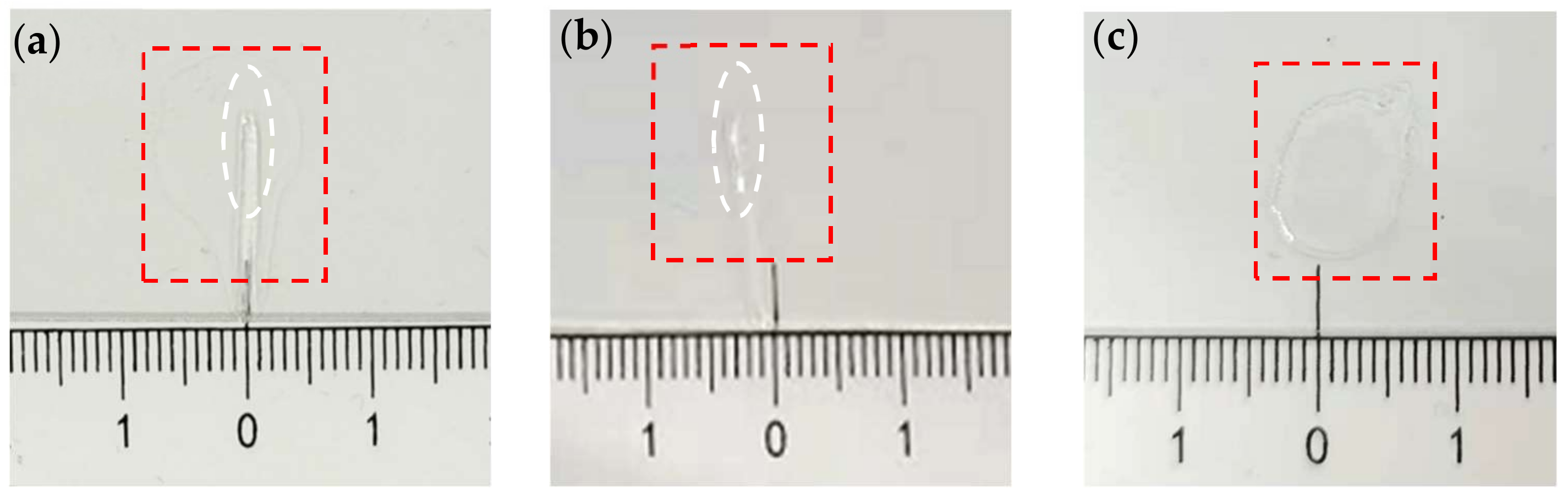
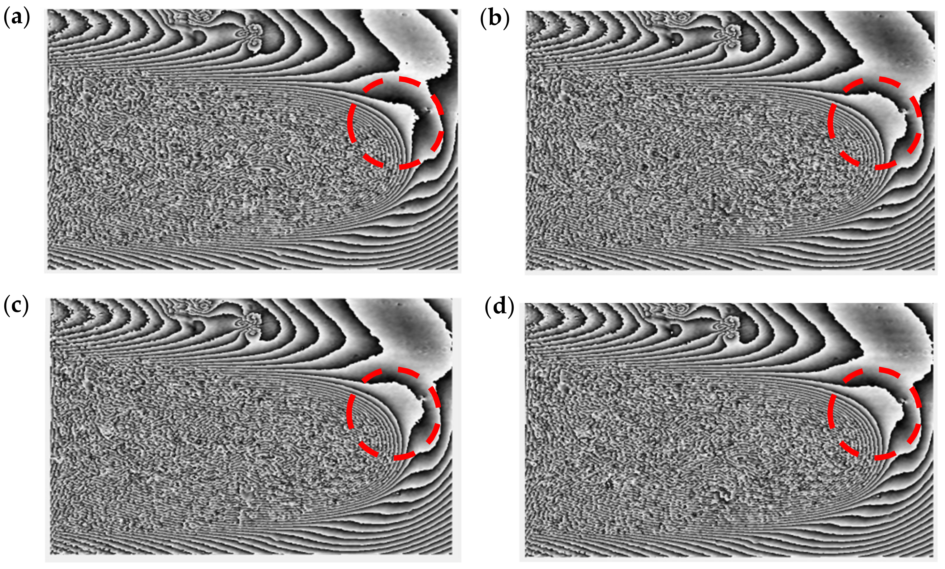
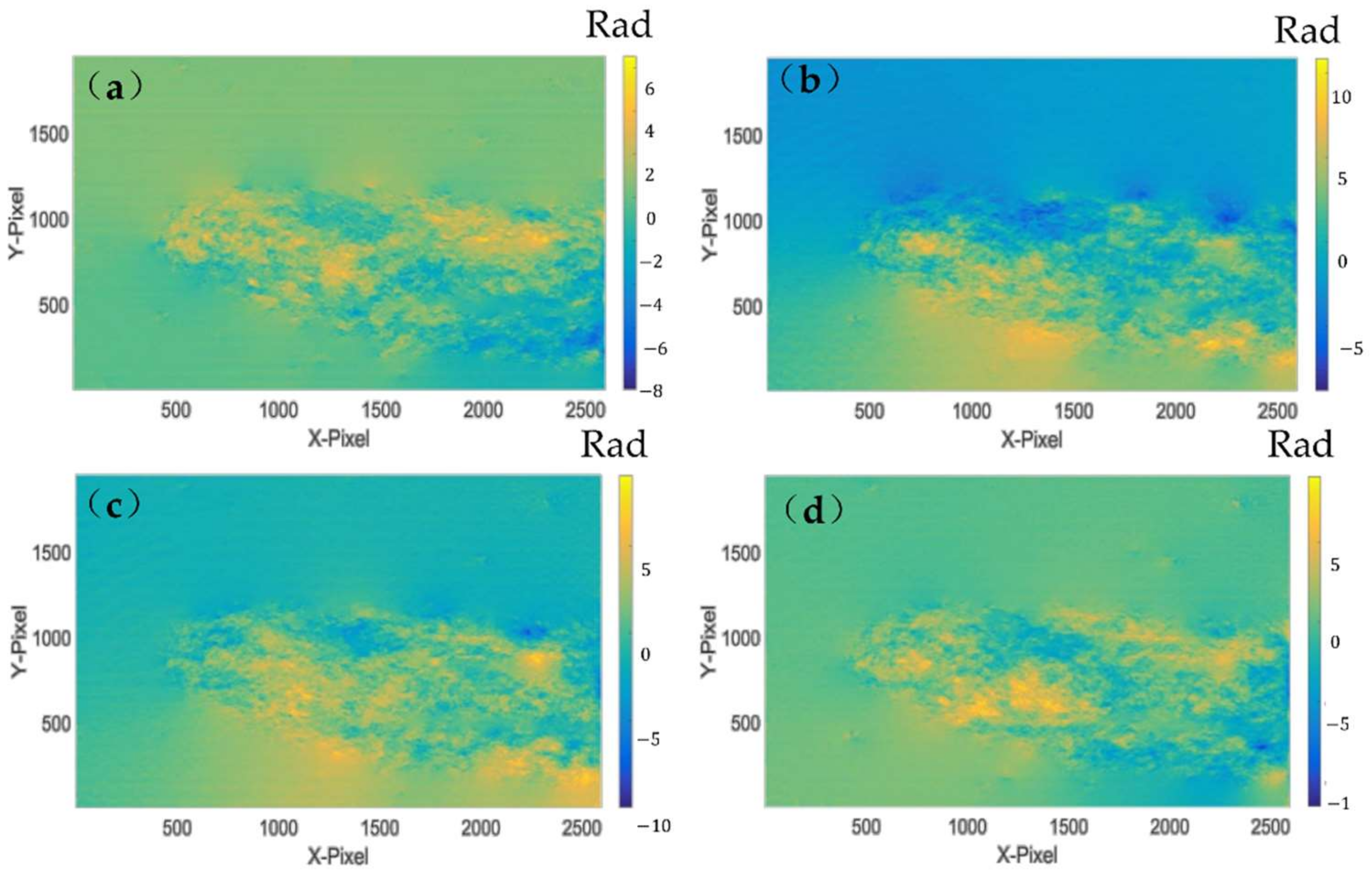
4. Experiment and Results

In the first phase, three groups of light sources to irradiate the tested sample were chosen. In order to increase the irradiation energy of the sample and to obtain a better crack growth effect, each group included two different wavelengths including 430 nm + 440 nm (near-ultraviolet light source, UV), 500 nm + 510 nm (visible light source), and 740 nm + 750 nm (near-infrared light source, IR). The irradiation duration of every group was 5 min.
Before the start of the irradiation experiment, digital holographic measurement was performed on the sample yielding an initial state hologram. The initial state measurement is shown in Figure 3a.
The experiments on the same sample were performed. Figure 3b shows the new phase after the sample was irradiated with a 740 nm + 750 nm laser; then, the same region was irradiated with a 430 nm + 440 nm laser and the phase is shown in Figure 3c. Furthermore, the same region was irradiated with a 500 nm + 510 nm laser and the new phase is shown in Figure 3d.
Figure 3b has an obvious change compared with Figure 3a; however, Figure 3b to Figure 3c and Figure 3d to Figure 3c have almost no change. It is therefore concluded that the largest phase change occurred in the crack head following the irradiation of 740 nm + 750 nm hybrid laser. The results of the phase images indicate that the laser in the near-infrared wavelength has a greater effect on crack growth than the light sources in the visible and near-ultraviolet wavelengths.
To further investigate the effect of laser irradiation on cracked samples from near-infrared wavelengths to infrared wavelengths, four different irradiation lasers are selected, namely, 740 + 750 nm hybrid laser, 840 + 850 nm hybrid laser, 940 + 950 nm hybrid laser, and 1040 + 1050 nm hybrid laser. The irradiation duration is also kept at 5 min, and the irradiation frequency is set as 5 MHz.
The control sample is shown in Figure 2c as a control variable in this stage.
Additional irradiation experiments are performed on the sample with a known crack and obtain the phase difference between the samples after irradiation and the initial state. The unwrapped phase results are shown in Figure 4.
Figure 4 shows that the cracked samples have all been expanded under laser irradiation in the near-infrared to infrared wavelength bands. The difference in the degree of extension, however, is not significant.
For further detailed analysis, the intercept lines at the head, middle, and tail positions of the cracks were extracted in each phase difference map in Figure 4 for contour analysis. The positions of the intercept lines in Figure 4d are shown in Figure 5. Three intercept lines are located at 457, 1625, and 2525 pixels of the x-axis on each map, respectively.
Taking contour lines for the four-phase difference results yield the results shown in Figure 6, Figure 7 and Figure 8.
Note that during the processing of the experimental results, different numbers of y-axis pixels are taken for the head, middle, and tail according to the size of the crack and transparent media cavity, with 200 pixels for the head and 950 pixels for both the middle and tail. In addition to considering the crack size, the significant change of contour line in the phase result is shown in Figure 6.
By comparing the phase changes in Figure 6, Figure 7 and Figure 8, the results show that the presence of tip cracks in the samples at different wavelengths of irradiation is an important factor in the phase transformation of the measured region. According to the pixel size and system magnification calculation, the crack growth distance for each of these groups (shown in Table 1) is obtained.
Analyzing the growth distance of the cracks given in Table 1, the combined laser irradiation of 1040 nm + 1050 nm has increased the growth distance of the crack head by 40.2% compared with the combined laser irradiation of 740 nm + 750 nm. The growth distance in the middle of the crack is 29.4% more than that of the combined laser of 740 nm + 750 nm. The growth distance at the tail of the crack is 17.9% more than that of the combined laser of 740 nm + 750 nm. By comparing the changes of different parts of the tested material exposed to different wavelengths of light, it is concluded that the head of the tip crack is more sensitive to the change of irradiation wavelength than the middle and tail of the crack. In addition, the middle and tail parts of the tip crack with a larger area within the tip crack are subjected to a larger phase change of laser irradiation under the same wavelength irradiation.
Comparing the growth distances of the middle, tail, and head of the tip crack under the same wavelength irradiation, it is evident that the growth distances of both the middle and tail of the crack are larger than those of the head of the crack, but the growth direction of the head of the crack is more definite. The reason could be that the complex map and internal energy conduction of the middle and tail parts of the crack trigger a more disordered phase transition and growth direction compared with the head of the tip crack.

5. Conclusions

DH has the advantages of having high resolution, being non-destructive, and operating in real-time in the imaging study of crack growth; therefore, DH is used to study the effect of laser irradiation on crack growth at the highest resolution. With this study, a method for detecting crack growth using a single-pulse laser with DH is proposed. The effect of different wavelengths of laser on crack growth is also investigated for Dammar varnish material, which is commonly used as an oil painting sealant.
It is concluded that near-infrared and infrared light irradiation is more effective than near ultraviolet and visible light irradiation for Dammar varnish materials. In addition, further experiments were conducted to study the phase changes of different parts of the crack under laser radiation. Based on this experimental study by DH, it is found that if there are tiny cracks on the surface material of the oil painting, the cracks easily expand and deteriorate under infrared radiation, thus causing damage to the oil painting; therefore, the light environment of infrared irradiation should be avoided as much as possible for preserving oil paintings. Similarly, in laser cleaning of older or more fragile oil paintings, the infrared wavelength laser needs to be used with caution to avoid irreversible damage to the artwork.
The proposed digital holography system can be made compact and portable and is thus feasible for cultural heritage preservation. The unique advantages of digital holography have been proved to be applicable to the study of minor damage in the field of cultural heritage; therefore, future work will include the study of tiny defects of non-transparent objects using digital holographic systems.

Author Contributions

Conceptualization, V.T. and W.Z.; methodology, V.T. and W.Z.; investigation, Z.C.; data curation, Y.L. and Y.C.; writing—original draft preparation, W.Z. and Y.L.; writing—editing, Y.L.; writing—review, V.T., Y.Y. and H.Z. All authors have read and agreed to the published version of the manuscript.

Funding

This research was funded by the National Natural Science Foundation of China (No. 61975112 and No. 52075314), the Major State Research Development Program of China (2020YFE024600), and the Shanghai Key Laboratory of Intelligent Manufacturing and Robotics.

Institutional Review Board Statement

Not applicable.

Informed Consent Statement

Not applicable.

Conflicts of Interest

The authors declare no conflict of interest.

References

  1. Tomkins, B. Fatigue Crack Propagation—An Analysis. Philos. Mag. 1968, 18, 1041–1066. [Google Scholar] [CrossRef]
  2. Zweig, D.; Venugopalan, V.; Deutsch, T.F. Stress generated in polyimide by excimer-laser irradiation. J. Appl. Phys. 1993, 74, 4181. [Google Scholar] [CrossRef]
  3. Gerasimov, A.B.; Chiradze, G.D.; Kutivadze, N.G. On the physical nature of a photomechanical effect. Semiconductors 2001, 35, 72–76. [Google Scholar] [CrossRef]
  4. Paltauf, G.; Dyer, P.E. Photomechanical Processes and Effects in Ablation. Chem. Rev. 2003, 103, 487–518. [Google Scholar] [CrossRef]
  5. Perez-Gutierrez, F.G. Photomechanical, Photothermal and Photothermomechanical Mechanisms of Interaction of Nanosecond Laser Pulses with Artificial Tissue Models and Pigmented Melanoma Cells in Medical Applications. Ph.D. Thesis, UC Riverside, Riverside, CA, USA, 2010. [Google Scholar]
  6. White, T.J. Photomechanical Effects in Materials, Composites, and Systems: Outlook and Future Challenges. In Photomechanical Materials, Composites, and Systems: Wireless Transduction of Light into Work; Wiley: Hoboken, NJ, USA, 2017; pp. 393–403. [Google Scholar]
  7. Miguel, P.; Robert, M.; Mattheij, M. Crack Propagation Analysis; Technische Universiteit Eindhoven: Eindhoven, The Netherlands, 2017. [Google Scholar]
  8. Bosco, E.; Suiker, A.S.J.; Fleck, N.A. Crack channelling mechanisms in brittle coating systems under moisture or temperature gradients. Int. J. Fract. 2020, 225, 1–30. [Google Scholar] [CrossRef]
  9. Menouillard, T.; Song, J.-H.; Duan, Q.; Belytschko, T. Time dependent crack tip enrichment for dynamic crack propagation. Int. J. Fract. 2010, 162, 33–49. [Google Scholar] [CrossRef]
  10. Tornari, V.; Tsiranidou, E.; Bernikola, E. Crack-Growth on Canvas Paintings during Transport Simulation Monitored with Digital Holographic Speckle Interferometry. Adv. Res. 2014, 2, 967–986. [Google Scholar] [CrossRef]
  11. Dias-da-Costa, D.; Valença, J.; Júlio, E.; Araújo, H. Crack propagation monitoring using an image deformation ap-proach: Crack Propagation Monitoring Using an Image Deformation Approach. Struct. Control. Health Monit. 2017, 24, e1973. [Google Scholar] [CrossRef]
  12. Réthoré, J. Automatic crack tip detection and stress intensity factors estimation of curved cracks from digital images: Automatic crack tip detection and SIF estimation of curved cracks. Int. J. Numer. Methods Eng. 2015, 103, 516–534. [Google Scholar] [CrossRef]
  13. Rezaie, A.; Achanta, R.; Godio, M.; Beyer, K. Comparison of crack segmentation using digital image correlation measurements and deep learning. Constr. Build. Mater. 2020, 261, 120474. [Google Scholar] [CrossRef]
  14. Elkhuizen, W.S.; Callewaert, T.W.J.; Leonhardt, E.; Vandivere, A.; Song, Y.; Pont, S.; Geraedts, J.M.P.; Dik, J. Comparison of three 3D scanning techniques for paintings, as applied to Vermeer’s ‘Girl with a Pearl Earring’. Heritage Sci. 2019, 7, 1–22. [Google Scholar] [CrossRef]
  15. Pouli, P.; Melessanaki, K.; Giakoumaki, A.; Argyropoulos, V.; Anglos, D. Measuring the thickness of protective coatings on historic metal objects using nanosecond and femtosecond laser induced breakdown spectroscopy depth profiling. Spectrochim. Acta Part B At. Spectrosc. 2005, 60, 1163–1171. [Google Scholar] [CrossRef]
  16. Malowany, K.; Tymińska-Widmer, L.; Malesa, M.; Kujawińska, M.; Targowski, P.; Rouba, B.J. Application of 3D digital image correlation to track displacements and strains of canvas paintings exposed to relative humidity changes. Appl. Opt. 2014, 53, 1739–1749. [Google Scholar] [CrossRef]
  17. Bacchin, P.; Brutin, D.; Davaille, A.; Di Giuseppe, E.; Chen, X.D.; Gergianakis, I.; Giorgiutti-Dauphiné, F.; Goehring, L.; Hallez, Y.; Heyd, R.; et al. Drying colloidal systems: Laboratory models for a wide range of applications. Eur. Phys. J. E 2018, 41, 94. [Google Scholar] [CrossRef]
  18. Georgiou, S.; Zafiropulos, V.; Anglos, D.; Balas, C.; Tornari, V.; Fotakis, C. Excimer laser restoration of painted artworks: Procedures, mechanisms and effects. Appl. Surf. Sci. 1998, 127–129, 738–745. [Google Scholar] [CrossRef]
  19. Bonarou, A.; Antonucci, L.; Tornari, V.; Georgiou, S.; Fotakis, C. Holographic interferometry for the structural diagnostics of UV laser ablation of polymer substrates. Appl. Phys. A 2001, 73, 647–651. [Google Scholar] [CrossRef]
  20. Tornari, V.; Bonarou, A.; Zafiropulos, V.; Antonucci, L.; Fotakis, C. Holographic interferometry sequential investi-gation of long-term photomechanical effects in the excimer laser restoration of artworks. In Proceedings of the ROMOPTO 2000: Sixth Conference on Optics, Bucharest, Romania, 4–7 September 2000; International Society for Optics and Photonics: Bellingham, WA, USA, 2000; Volume 4430, pp. 153–159. [Google Scholar]
  21. Athanassiou, A.; Andreou, E.; Bonarou, A.; Tornari, V.; Anglos, D.; Georgiou, S.; Fotakis, C. Examination of chemical and structural modifications in the UV ablation of polymers. Appl. Surf. Sci. 2002, 197–198, 757–763. [Google Scholar] [CrossRef]
  22. Esposito, E.; Scalise, L.; Tornari, V. Measurement of stress waves in polymers generated by UV laser ablation. Opt. Lasers Eng. 2002, 38, 207–215. [Google Scholar] [CrossRef]
  23. Tornari, V. Delocalized Photomechanical Effects of UV ns Laser Ablation on Polymer Substrates Captured by Optical Holography Workstation: An Overview on Experimental Result. Adv. Opt. 2014, 2014, 1–13. [Google Scholar] [CrossRef] [Green Version]
  24. Tornari, V.; Andrianakis, M.; Chaban, A.; Kosma, K. Heat Transfer Effects on Defect Boundaries Captured by Digital Holographic Interferometry and Infrared Thermography Workstation: An Overview on Experimental Results. Exp. Tech. 2020, 44, 59–74. [Google Scholar] [CrossRef]
  25. Pan, A.; Wang, W.; Mei, X.; Zheng, B.; Yan, Z. Cracks growth behaviors of commercial pure titanium under nanosecond laser irradiation for formation of nanostructure-covered microstructures (with sub-5-μm). Appl. Surf. Sci. 2016, 387, 1046–1053. [Google Scholar] [CrossRef]
  26. Eto, S.; Miura, Y.; Tani, J.; Fujii, T. Effect of residual stress induced by pulsed-laser irradiation on initiation of chloride stress corrosion cracking in stainless steel. Mater. Sci. Eng. A 2014, 590, 433–439. [Google Scholar] [CrossRef]
  27. Huang, H.; Noguchi, J.; Yan, J. Shield gas induced cracks during nanosecond-pulsed laser irradiation of Zr-based metallic glass. Appl. Phys. A 2016, 122, 881. [Google Scholar] [CrossRef]
  28. Pouli, P.; Oujja, M.; Castillejo, M. Practical issues in laser cleaning of stone and painted artefacts: Optimisation procedures and side effects. Appl. Phys. A 2012, 106, 447–464. [Google Scholar] [CrossRef]
  29. Tam, A.C.; Leung, W.P.; Zapka, W.; Ziemlich, W. Laser-cleaning techniques for removal of surface particulates. J. Appl. Phys. 1992, 71, 3515–3523. [Google Scholar] [CrossRef]
  30. Myridis, N.E. Lasers in the Preservation of Cultural Heritage: Principles and Applications, by C. Fotakis, D. Anglos, V. Zafiropulos, S. Georgiou, and V. Tornari. Contemp. Phys. 2012, 53, 288–289. [Google Scholar] [CrossRef]
  31. Tornari, V.; Fantidou, D.; Zafiropulos, V.; Vainos, N.A.; Fotakis, C. Photomechanical effects of laser cleaning: A long-term non-destructive holographic interferometric investigation on painted artworks. SPIE 1998, 3411, 420–430. [Google Scholar]
  32. Tornari, V.; Zafiropulos, V.; Vainos, N.A.; Fantidou, D.; Fotakis, C. Discrimination of photomechanical effects in the laser cleaning of artworks by means of holographic interferometry. In Optics and Lasers in Biomedicine and Culture; Springer: Berlin/Heidelberg, Germany, 2000; pp. 208–212. [Google Scholar]
  33. Tiennot, M.; Paardekam, E.; Iannuzzi, D.; Hermens, E. Mapping the mechanical properties of paintings via nanoindentation: A new approach for cultural heritage studies. Sci. Rep. 2020, 10, 1–8. [Google Scholar] [CrossRef]
  34. Schuh, C.A. Nanoindentation studies of materials. Mater. Today 2006, 9, 32–40. [Google Scholar] [CrossRef]
  35. Gautham, S.; Sasmal, S. Recent Advances in Evaluation of intrinsic mechanical properties of cementitious composites using nanoindentation technique. Constr. Build. Mater. 2019, 223, 883–897. [Google Scholar] [CrossRef]
  36. Gai, S.; Da, F.; Dai, X. A novel dual-camera calibration method for 3D optical measurement. Opt. Lasers Eng. 2018, 104, 126–134. [Google Scholar] [CrossRef]
  37. Trivedi, V.; Joglekar, M.; Mahajan, S.; Patel, N.; Chhaniwal, V.; Javidi, B.; Anand, A. Digital holographic imaging of refractive index distributions for defect detection. Opt. Laser Technol. 2019, 111, 439–446. [Google Scholar] [CrossRef]
  38. Deng, Y.; Hong, W.; He, J.; Guo, Z.; Chen, Y.; Huang, Z. Micro-cracks on crosslinked Poly(dimethylsiloxane) (PDMS) surface treated by nanosecond laser irradiation. Appl. Surf. Sci. 2018, 445, 488–495. [Google Scholar] [CrossRef]
  39. Chen, G.; Zhou, W.; Hu, Z.; Zhou, Q.; Zhang, W. Surface roughness measurement based on digital holography. J. Appl. Opt. 2014, 35, 1040–1047. [Google Scholar] [CrossRef]
  40. Zhou, W.-J.; Li, B.-Y.; Shen, H.-X.; He, D.-K.; Zhang, H.-B.; Yu, Y.-J.; Tornari, V. Tip Crack Imaging on Transparent Materials by Digital Holographic Microscopy. J. Imaging 2019, 5, 80. [Google Scholar] [CrossRef] [Green Version]
  41. Masayuki, A.; Kenji, I.; Tomoki, M.; Kiyohiro, I.; Hiroki, Y.; Tatsuo, S. Delaying Effect of Fatigue Crack Propagation by Single-Pulse Laser Irradiation. Proceedings 2018, 2, 478. [Google Scholar]
  42. Zhou, W.; Peng, K.; Yu, Y. Surface roughness measurement and analysis of mechanical parts based on digital ho-lography. Adv. Manuf. 2016, 4, 217–224. [Google Scholar] [CrossRef]
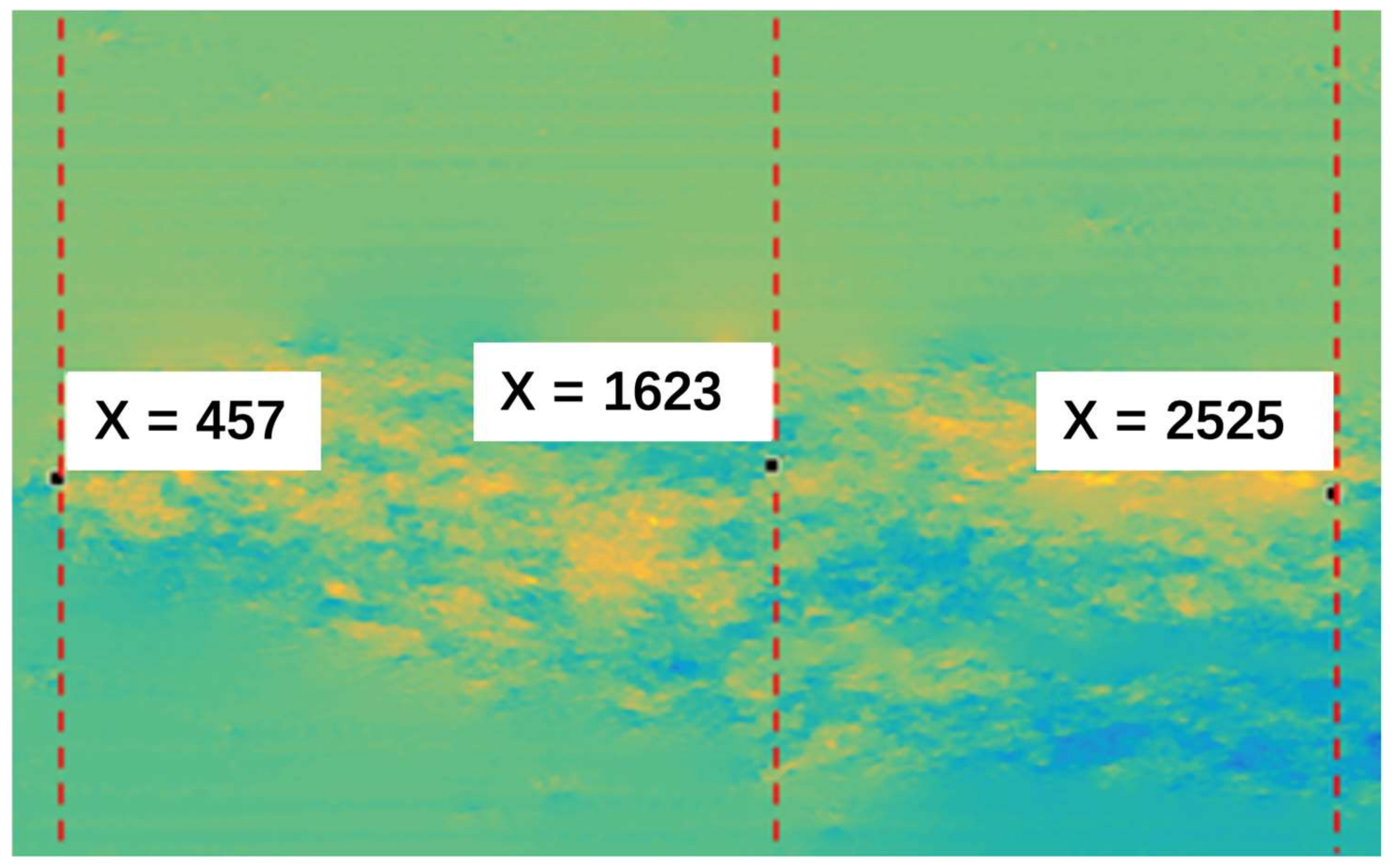
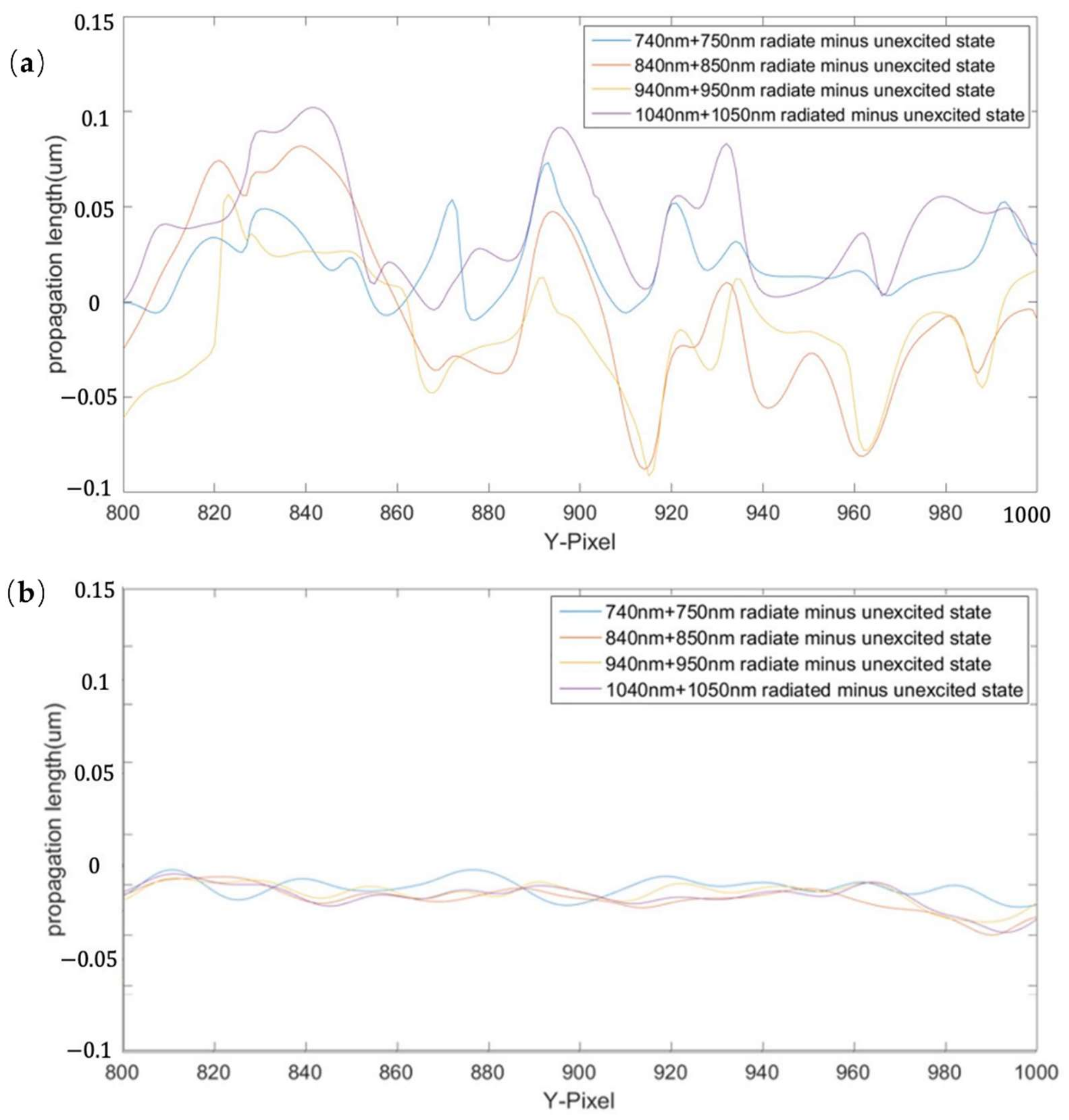
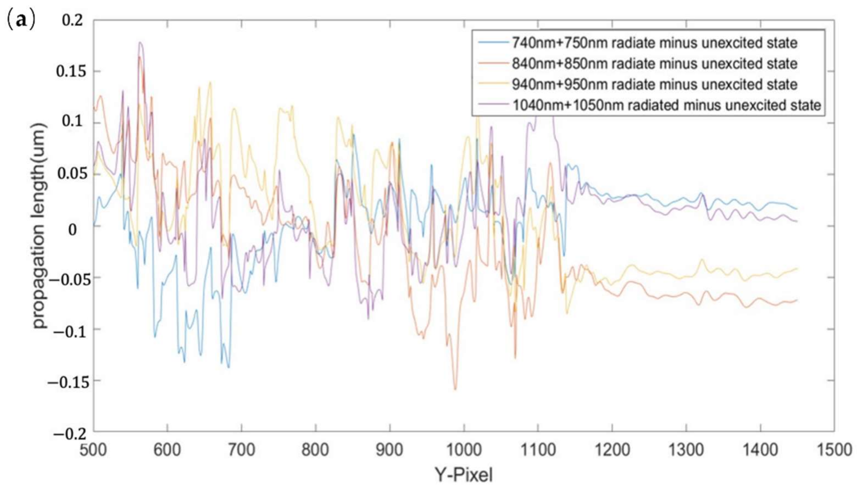
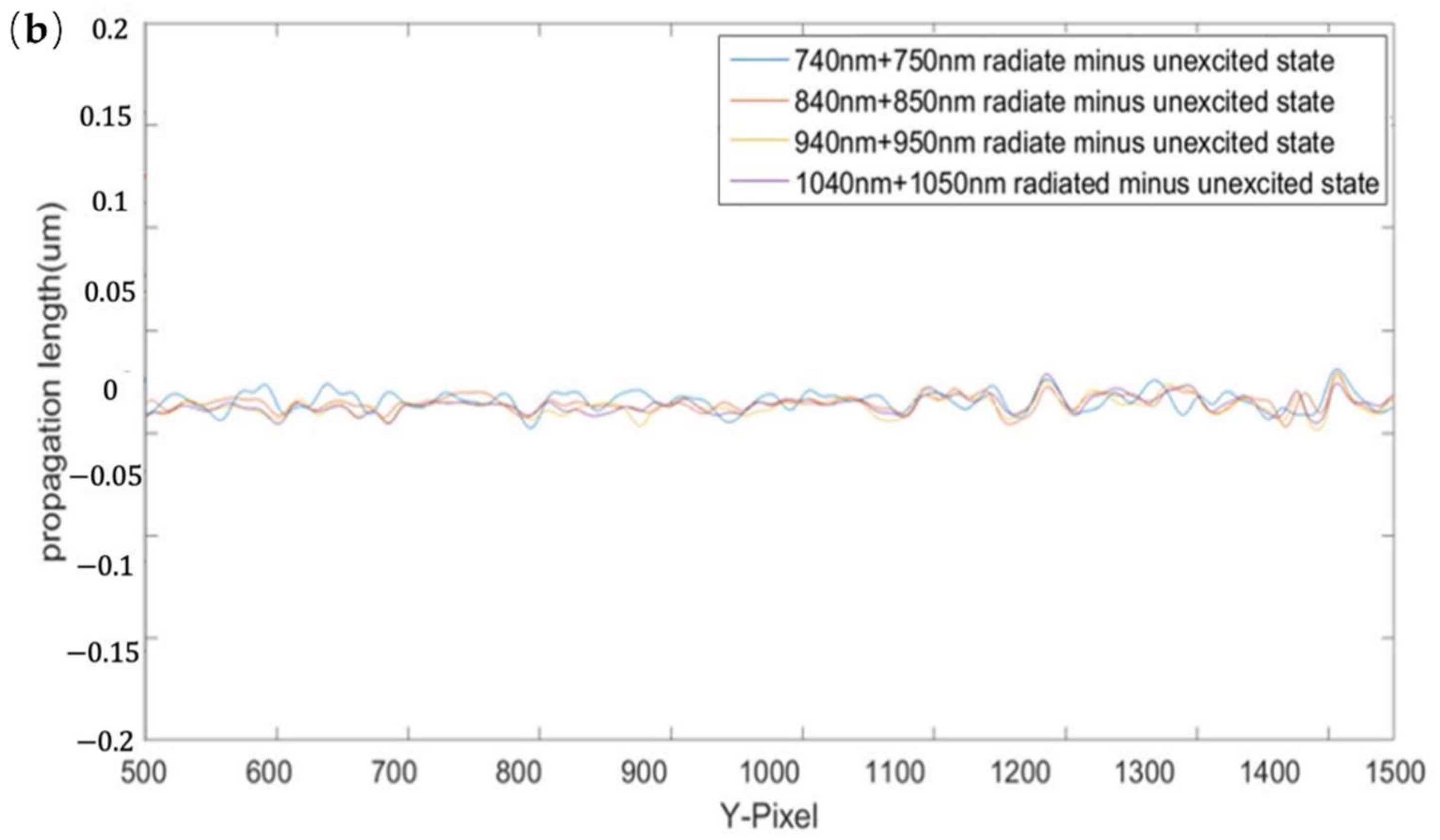
Figure 1. Schematic diagram of the optical path system, both legs of the optical setup are seen LASER-M4-L3 as pumping and LASER-M1-BS1-CCD as probe.
Applsci 12 07799 g001
Figure 2. (a) Crack sample in the first phase, (b) crack sample in the second phase, and (c) crack-free sample.
Applsci 12 07799 g002
Figure 3. Hologram phases: (a) initial state; (b) 740 nm + 750 nm laser irradiation; (c) 430 nm + 440 nm laser irradiation; (d) 500 nm + 510 nm laser irradiation. Red Circle highlights the changes.
Applsci 12 07799 g003
Figure 4. Post Irradiation phase difference of the tip crack. (a) Post irradiation at 740 nm + 750 nm; (b) after irradiation at 840 nm + 850 nm; (c) after irradiation at 940 nm + 950 nm; (d) after irradiation at 1040 nm + 1050 nm.
Applsci 12 07799 g004
Figure 5. Position of the contour line of the phase difference.
Applsci 12 07799 g005
Figure 6. Contour line of phase difference at X = 457 for the position of the intercept line: (a) experimental results; (b) control experimental results.
Applsci 12 07799 g006
Figure 7. Contour line of phase difference at the intercept position of X = 1625: (a) experimental results; (b) control experimental results.
Applsci 12 07799 g007aApplsci 12 07799 g007b
Figure 8. Contour line of phase difference at the intercept position of X = 2525: (a) experimental results; (b) control experimental results.
Applsci 12 07799 g008
Table 1. Crack growth distance between experimental and control groups at different irradiation wavelengths (unit: μ m).
Irradiation Wavelength (nm)740 + 750840 + 850940 + 9501040 + 1050
Experimental group X = 4570.0720.0870.0900.101
Control group X = 4570.0010.0010.0050.004
Experimental group X = 16250.1360.1380.1340.176
Control group X = 16250.0160.0160.0230.018
Experimental group X = 25250.1680.1660.1630.198
Control group X = 25250.0080.0130.0060.014
Publisher’s Note: MDPI stays neutral with regard to jurisdictional claims in published maps and institutional affiliations.

