
One-Coil Long-Stroke Permanent Magnetic Actuator Design Applied to Load Breaker Switch for Railway


1
Power Electric Apparatus R&D Institute, ENTEC Electric & Electronic Co., Ltd., 225-38 Choerubaek-ro, Bongdam-eup, Hwaseong-si 18329, Korea
2
Department of Transportation Engineering, Korea University of Science & Technology, 217 Gajeong-ro, Yuseong-gu, Daejeon 34113, Korea
3
Smart Electrical & Signaling Division, Korea Railroad Research Institute, 176 Cheoldobangmulgwan-ro, Uiwang-si 16105, Korea
*
Author to whom correspondence should be addressed.
Appl. Sci. 2022, 12(16), 8214; https://0-doi-org.brum.beds.ac.uk/10.3390/app12168214
Submission received: 22 July 2022
/
Revised: 12 August 2022
/
Accepted: 15 August 2022
/
Published: 17 August 2022
(This article belongs to the Topic Transportation in Sustainable Energy Systems)
Abstract
:This paper proposes a design for a one-coil long-stroke permanent magnet actuator (PMA) applied to a load breaker switch with a novel mechanism applicable to railways. As a new load breaker switch applicable to railway overhead lines has a double-insulation structure of the vacuum interrupter (VI) and a disconnect switch (DS) for higher insulation, the actuator to control the switch requires a very long stroke. While the traditional mechanism of the PMA implements a stroke of 10 to 30 mm, the load breaker switch with a double-insulation structure requires a stroke of 120 mm. To do so, we used the finite element method (FEM) and designed a novel one-coil long-stroke PMA. Then, values from FEM analysis were compared with measured holding force data, and a simplified prototype test-jig was used to confirm the actuator’s operating characteristics. In addition, the electromagnetic force, plunger rotation, and part weight ratio, which affect operating performance, were adapted in its design. By doing so, we confirmed the operating performance required for the one-coil long-stroke PMA for a new load breaker switch with a double-insulation structure with a VI average opening speed of 1.4 m/s and an average closing speed of 0.9 m/s at 1/2 of full stroke.
1. Introduction
In general, switches used to protect the railway system include circuit breakers (CBs), switches (SWs), and disconnecting switches (DSs). While most of these switches are installed at substations or power stations, load breaker switches or DSs are installed on railway tracks to provide and shut down power to the tracks. In the past, load breaker switches or DSs installed on railway tracks adopted the open type, which was exposed. Now, they adopt a solid insulated type to prevent electric shock accidents during work and require no maintenance [1,2,3].
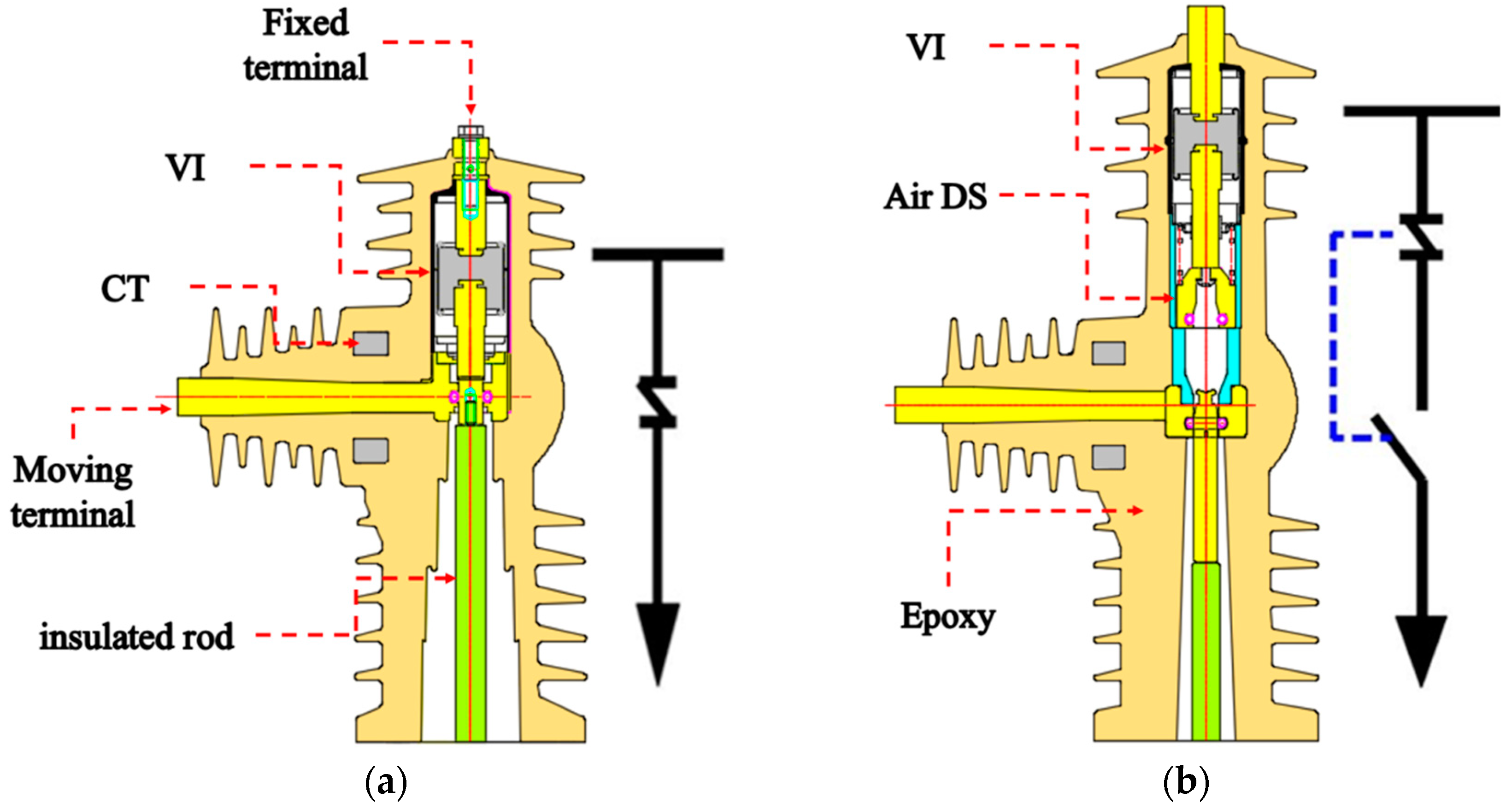
Conventional solid insulated load breaker switches, however, solely rely on the vacuum interrupter (VI) for opening performance, as shown in Figure 1a. As a result, the gap with the part contacting the VI is short during opening, causing induced voltage and destroying insulation due to decreased insulation performance by the epoxy. To overcome such safety problems with insulation, a load breaker switch with double insulation serially combining the VI and AIR was studied, as shown in Figure 1b. This serial structure of VI+AIR DS has advantages: it ensures a gap to discourage current leakage, achieves insulation performance in AIR DS in the event of an external surge, maintains insulation performance in AIR DS during decreased VI vacuum, and thereby minimizes concerns for any electric shock [4,5].
The novel solid insulated load breaker switch with a VI+AIR DS structure has the advantage of a longer distance through the insulation, but the operating stroke increases by 5 to 10 times compared with the conventional one with a VI structure. As the motor spring charging mechanism generally applied for long-stroke operation has maintenance difficulties due to its complex structure and many parts, the solid insulated load breaker switch, which has a relatively simple structure, uses fewer parts, and shows good durability, is effective for PMAs and is useful for many applications [6].
In the case of the general PMA method, although it has various advantages, it has the disadvantage of a short stroke [7,8]. To apply a long stroke, an auxiliary opening/closing coil to the typical type of PMA can be applied [9]. However, this PMA method increases the volume of the coil and actuator. Additionally, this PMA’s opening and closing holding forces could not be designed independently.
Nonetheless, the conventional PMA has a stroke of 10 to 30 mm and is not applicable to the new load breaker switch with double insulation presented in this paper. Hence, we designed a 120 mm one-coil long-stroke mechanism to ensure stroke performance in a novel load breaker switch with double insulation and confirmed its operating characteristics and design suitability by comparing FEM analysis values and measured holding force data and producing a simplified prototype [10].
2. Permanent Magnet Actuator for Long-Stroke
The plunger receives electromagnetic force with the magnetic field generated from the electric current applied to coils and operates in the traditional PMA, as shown in Figure 2. The permanent magnet maintains the closing and opening of the plunger, and the electric current is supplied to the closing oil and opening coils, thereby conducting closing and opening operations. It is difficult to lengthen a stroke with this mechanism due to its structure. As a stroke lengthens, the area overlapping with the coils on both ends decreases, which weakens the driving force, and the actuator must become much bigger to increase the area overlapping with the coils, which reduces the efficiency in delivering the force [7].
The mechanism in Figure 3 was designed to make it easy to lengthen a stroke, and is divided into the holding and driving parts. In the holding part, permanent magnets maintain the closing and opening of the plunger. In the driving part, the coils operate after receiving the electromagnetic force when the electric current is applied to the coils between the permanent magnets. This type of actuator allows the easy lengthening of a stroke. Lengthening permanent magnets in the driving part would make it possible to design a PMA that has almost the same driving force across stroke intervals. As it is divided into holding and driving parts, however, it has a disadvantage of becoming too large as the length increases by the lengthened stroke occurring in two parts [11].
Figure 4 shows the structure of the one-coil type PMA suggested in this paper. Previously, research was conducted by applying the manipulator method to the recloser, and verification was performed through a short-circuit test. The rated voltage of the studied prototype was 27 kV, the short-time current was 16 kA, and the stroke was 18.5 mm. The rating proposed in this paper is 29 kV, which is higher than the conventional one, and the short-time current is 20 kA, which requires more energy, and the stroke is about 6.5 times of 120 mm. A study was conducted to design an efficient design and address problems that arise as the stroke and load increase. The close state is maintained by the plunger through permanent magnets, while the open state is maintained by the open spring.
3. Design of the One-Coil Long Stroke PMA
3.1. Analysis of the Magneto-Static Field and Prototype Design
The circuit, motion, and magnetic field equations are required for the FEM analysis of an actuator. Figure 5 shows the equivalent circuit, the actuator’s voltage source applies the electric current to a coil through electrostatic discharge by the capacitor, and Equation (1) is the equivalent circuit equation. Here, C is capacitance, R is resistance, and L is inductance.
Equation (2) expresses the motion equation. Here, F is force of plunger, M is mass of driving parts, B is damping constant, K is spring constant, and is frictional force.
Equations (3) and (4) express the magnetic field equation. Here, is magnetic flux density, is permeability, is magnetic susceptibility, is magnetic field intensity, is current density, and is magnetization.
Figure 6 shows the magnetic flux vector depending on the closing and opening operation of the one-coil actuator using the material properties described on Table 1. For the closing operation, the electromagnetic force from a coil compresses the open spring. This structure is efficient for the closing operation, as the direction of the magnetic flux vector by the permanent magnets is the same as that of a coil during closing. For the opening operation, electric current is applied to a coil in the opposite direction from the closing operation, offsetting the holding force with the magnetic flux vector by permanent magnets and that by a coil in the opposite direction. The opening operation is conducted with the force of the open spring compressing during the closing operation. The holding force can be offset by a small electric current, and the opening operation is mostly conducted by the force of the open spring. A single coil enables a compact design, and it can be operated by low electric power during the opening operation. As the spring is used for the opening operation, it has the disadvantage of requiring more energy to compress the spring for the closing operation.
Figure 7 is a flow chart for one-coil long-stroke PMA development. The validity of the analysis was verified by making a prototype through FEM analysis and comparing the data. Through the test of the prototype, the parts that needed improvement were supplemented, and we confirmed whether the standards of the required specifications were satisfied.
3.2. Holding Force
Table 2 provides the specifications of the load breaker switch with double insulation applied in this study. This specification refers to the VI specification datasheet. The most important factor in the design of this load breaker switch was selecting the holding force. The holding force was obtained by adding the contact force + open spring force–VI vacuum hold force + margin. A margin of at least 300 N is recommended. If the margin is too high, it requires a higher increase in the electric current to offset the holding force during the opening operation, which prolongs the opening time. A long opening time is problematic if a circuit breaker is applied. A long opening time poses no problem if a load breaker switch is used.
As the required holding force of a double-insulation load breaker switch needs to be adjusted according to the specifications while checking the characteristics of the open spring force, an overall holding force of 3500 to 4000 N was selected with the open spring force + margin as 1500 to 2000 N.
Figure 8 shows the PMA holding force of the double-insulation load breaker switch and expresses magnetic flux density and magnetic flux vector with axisymmetric model analysis data from the finite element method. The empty space between plungers is intended for the open spring. The little space at the bottom core, which is in contact with the plunger, was designed to allow the air to leave during closing and opening operations and poses no problem to the operation due to the increased pressure. The results of FEM analysis showed the holding force is 3996 N and meets the required specifications for a load breaker switch.
To confirm whether the FEM analysis value was suitable, a simplified prototype test-jig was produced and then the holding force was measured, as shown in Figure 9a. By connecting the pulling jig, the load cell, and the PMA plunger, the holding force as the load cell was pulled was measured, and this value was checked on the indicator. As shown in Table 3, The value measured by the load cell was about 3800 N, which was 5.2% different from the analysis value and confirmed that it achieved the holding force required for the load breaker switch. A flowchart of the holding force measurement with the prototype test-jig is illustrated in Figure 9b.
3.3. Electromagnetic Force
Figure 10 illustrates a comparison of the results of magnetic flux density with the electric current applied to conduct the closing operation during opening depending on the presence of a gap between the plunger and core. Figure 10a shows the magnetic flux density when there was no gap between the plunger and core, while Figure 10b shows the magnetic flux density when there was a gap between the plunger and core. During operation analysis, the absence of the gap led to a pull between the core and plunger, which weakened the electromagnetic force in the closing direction and showed poor characteristics during the initial operation. As such, a nonmagnetic Al 2 mm gap was designed to be beneficial for initial operation.
As shown in Figure 11, the open spring was designed as 1000 N and closed, and the characteristics were confirmed: the closing operation waveform rapidly slowed at the middle stroke point, touched the contact point, stopped at the add contact spring force compression interval, and completed closing.
To analyze what caused the slowdown during the closing operation, dynamic characteristics analysis was conducted, as shown in Figure 12, which shows the electromagnetic force of the closing operation. For FEM analysis, transient analysis was performed by applying weight, coil data, and external load values (spring force, add contact force, VI vacuum hold force, etc.) according to position. At the indicated middle stroke point, there is an interval where the electromagnetic force is on the rise and then declines. In this part, there is a high magnetic flux density in the direction of the center of the coil. As the stroke is long, once it passes the middle point, the force is received in the direction of the central position. Then, the plunger continues to move due to inertia, and when it reaches the closing location, closing is maintained by the electromagnetic force of the permanent magnet. As a lot of load works in the middle part, as shown in Figure 12, and slows the stroke, it is important to reduce the load at the interval where the electromagnetic force declines.
As shown in Figure 13 (left), one open spring compressed the entire interval, and therefore, a large force was received at the middle stroke point. To solve this, a double spring was designed as shown in Figure 13 (right). The primary open spring was applied to the entire stroke interval, and the force to maintain opening was designed with a low spring constant (k). The secondary open spring was designed so that the spring could not be compressed during the initial closing operation but would work only during the VI interval. As the load electric current during opening was shut off by the VI, only the speed specifications at the VI interval needed to be satisfied. Hence, the large force at the VI interval was designed with a high spring constant (k).
The spring force curve is provided in Figure 14, where the open state is expressed as 0 mm and the close state as 120 mm. The primary open spring was designed to have a compression force of 100 N during the initial input operation and 200 N when the input was completed. The secondary open spring was designed to be completed at 800 N when the compression started at 100 mm.
When the LBS was assembled to the PMA, it was assembled in the opposite direction to that shown in Figure 13. The gravity direction of the secondary open spring was designed as the direction of the plunger, and the free field of the spring was designed to be larger than the stroke so that it could not come off outside.
3.4. Plunger Rotation
Because PMA plungers are cylindrical, they are slightly rotated by the electromagnetic force, as shown in Figure 15a. This rotation produces a load onto the part linked to the plunger, which is not good for durability or characteristics. To prevent this rotation, a guide bar was applied, as shown in Figure 15b. While this guide bar prevents the plunger from rotating, there is a concern that the mechanical friction load may increase.
3.5. Part Weight Ratio
The actuator moving part moves up to the add contact spring interval, including the plunger and open spring, while the interrupter moving part moves up to the add contact spring interval, including the VI movable electrode and insulation load. The weight ratio of the actuator moving part and the interrupter moving part is an important factor for operation. In particular, the electric current applied to a coil during opening operation generates an inverse magnetic field to offset the holding force, and then the actuator moving part moves past the add contact spring interval and leads the interrupter moving part to operate. If the interrupter moving part is much heavier than the actuator moving part, deceleration occurs after the add contact spring interval, as shown in Figure 16, which may lead to a problem with shut-off performance. A higher rating of the switch has a heavier interrupter moving part; therefore, if the actuator moving part is too heavy, the overall operation speed may slow down and result in a problem. Hence, it is necessary to select the overall weight by considering operating characteristics.
4. Operating Characteristics of the One-Coil Long-Stroke PMA
Figure 17 and Table 4 show the curve and data of the characteristics for the finally designed one-coil long-stroke PMA during the opening and closing of the load breaker switch with double insulation.
A stroke was measured in the PMA with linear variable resistance. The charging voltage of the capacitor was 140 V, and the capacitance was 68,000 uF. The induced voltage time was set to 250 ms during closing operation and for opening operation to 60 ms. The closing and opening times were measured from the time of induced current to the time of contact connection and disconnection. The peak current was measured between the closing and opening times. As for the operating speed, the average speed of 50% of the VI section was measured according to the VI specifications datasheet. The input speed was 0.9 m/s and the opening speed was 1.4 m/s, which satisfy the specifications required by VI, as presented in Table 2.
5. Conclusions
We designed a 120 mm one-coil long-stroke PMA applied to a double-insulation load breaker switch with a novel mechanism applicable to railways. In the case of a structure with a long stroke, it is necessary to use a motor spring mechanism that requires a lot of maintenance. The proposed AIR+DS structure uses a long stroke, but the PMA method, which is commonly used with short strokes, is applied. With efficient energy design, long-stroke PMA can be used to ensure economic feasibility with a simple structure and low maintenance. To implement the PMA, the FEM was used to design the one-coil long-stroke PMA, and a comparison of FEM analysis values and measured holding force data was conducted to confirm operating characteristics. In addition, the electromagnetic force, plunger rotation, and part weight ratio, which affect operating performance, were adapted in its design. As such, we confirmed the operating performance required for the one-coil long-stroke PMA for a new load breaker switch with double insulation. In addition, we plan to verify the capability of the proposed actuator through making and braking current tests, and we plan to develop actuators that can be applied to switches and circuit breakers with higher ratings that require a longer stroke than a switch with the suggested rating.
Author Contributions
Conceptualization, S.-J.K. and H.J.; methodology, H.J.; software, Y.-I.K.; investigation, H.J.; data curation, J.-H.H.; writing—original draft preparation, S.-J.K.; writing—review and editing, C.-M.Y.; supervision, Y.-I.K.; project administration, C.-M.Y.; funding acquisition, H.J. All authors have read and agreed to the published version of the manuscript.
Funding
This research was supported by a grant from R&D Program of the Korea Railroad Research Institute, Republic of Korea (PK2204B1A).
Conflicts of Interest
The authors declare no conflict of interest.
References
- Duanlei, Y.; Hongfei, Z.; Junping, C.; Hongyan, W.; Min, L. Investigation of 63kV High Voltage Vacuum Circuit Breaker of Single Phase Bipolar Used on Railway. In Proceedings of the 2011 1st International Conference on Electric Power Equipment—Switching Technology, Xi’an, China, 23–27 October 2011. [Google Scholar]
- Jankowski, P.; Mindykowski, J. Study on the Hazard Limitation of Hybrid Circuit Breaker Actuator Operation. Energies 2018, 11, 416. [Google Scholar] [CrossRef]
- Choi, S.J.; Lim, S.H. Impact on Current-Interrupting Characteristic by Parameter Settings of Superconducting Hybrid DC Circuit Breaker. Energies 2021, 14, 2469. [Google Scholar] [CrossRef]
- Song, X.; Mengyuan, T.; Yang, R.; Yuhang, L.; Zhizong, Y.; Yixiang, S.; Hao, H.; Guoqiang, G.; Guangning, W.; Yaoyao, J.; et al. The characteristic analysis of the operational overvoltage caused by the vacuum circuit breakers on High-speed trains. J. Electr. Eng. Technol. 2022, 17, 221–236. [Google Scholar]
- Choi, M.; Kim, J.; Park, C.; Koh, H.; Kim, Y. A Study of Electrostatic Induced Voltage between the Contacts in Vacuum Interrupter of 25.8kV MV VCB. In Proceedings of the 2022 6th International Conference on Electric Power Equipment—Switching Technology ICEPE-ST, Seoul, Korea, 15–18 March 2022. [Google Scholar]
- Krebs, G.; Tounzi, A.; Pauwels, B.; Willemot, D.; Piriou, F. Modeling of A Linear and Rotary Permanent Magnet Actuator. IEEE Trans. Magn. 2008, 44, 4357–4360. [Google Scholar] [CrossRef]
- Fang, S.; Lin, H.; Ho, S.L. Transient Co-Simulation of Low Voltage Circuit Breaker with Permanent Magnet Actuator. IEEE Trans. Magn. 2009, 45, 1242–1245. [Google Scholar] [CrossRef]
- Ro, J.; Hong, S.; Jung, H. Characteristic analysis and design of a novel permanent magnetic actuator for a vacuum circuit breaker. IET Electr. Power Appl. 2012, 7, 87–97. [Google Scholar] [CrossRef]
- Cai, Z.; Ma, S.; Wang, J. An Approach of Improve Permanent Magnetic Actuator of Vacuum Circuit Breaker. In Proceedings of the 2008 23rd International Symposium on Discharges and Electrical Insulation in Vacuum, Bucharest, Romania, 15–19 September 2008. [Google Scholar]
- Jung, H. Optimal Design and Dynamic Characteristic Analysis of a New Type Electric Actuator for High Voltage Circuit Breaker. In Proceedings of the 2008 International Conference on Electrical Machines and Systems, Wuhan, China, 20 October 2008. [Google Scholar]
- Kim, S.; Hahn, S.; Kim, Y.; Koh, H.; Choi, M. Numerical Investigation for Dynamic Characteristic Analysis of Electromagnetic Actuator for Gas Circuit Breakers. In Proceedings of the 2015 3rd International Conference on Electric Power Equipment–Switching Technology (ICEPE-ST), Busan, Korea, 25–28 October 2015. [Google Scholar]
- Cho, D.; Hong, S.; Woo, D.; Jung, H. Design of Electromagnetic Force driving Actuator for Automatic Transfer Breaker Based on Three-Link Structure. In Proceedings of the 2011 International Conference on Electrical Machines and Systems, Beijing, China, 23 August 2011. [Google Scholar]
- Bae, B.; Kang, J.; Jung, H. Design of Electromagnetic Actuator with 3-bar Linkage Mechanism for Low Voltage Circuit Breaker. In Proceedings of the the 7th International Symposium on Linear Drives for Industry Applications, Incheon, Korea, 20–23 September 2009. [Google Scholar]
Figure 1.
VI structure and VI+AIR DS structure: (a) conventional VI structure and (b) new VI+AIR DS structure.
Figure 1.
VI structure and VI+AIR DS structure: (a) conventional VI structure and (b) new VI+AIR DS structure.

Figure 2.
A traditional PMA type with plunger.

Figure 3.
A traditional PMA type with holding and driving parts.

Figure 4.
The proposed PMA-type one-coil actuator.

Figure 5.
Equivalent circuit.

Figure 6.
Magnetic flux vector of one-coil actuator during (a) opening and (b) closing operations.

Figure 7.
Flowchart for the development of one-coil long-stroke PMA.

Figure 8.
Magnetic flux density and magnetic flux vector of PMA in (a) closed and (b) open states.

Figure 9.
(a) Holding force measurement with prototype test-jig. (b) Flowchart of holding force measurement.
Figure 9.
(a) Holding force measurement with prototype test-jig. (b) Flowchart of holding force measurement.

Figure 10.
The magnetic flux density of the current applied in the open state (a) without and (b) with a gap.
Figure 10.
The magnetic flux density of the current applied in the open state (a) without and (b) with a gap.

Figure 11.
Characteristics of closing operation.

Figure 12.
Data of operating characteristics obtained from FEM analysis.

Figure 13.
Open spring designs of single spring type (Left) and double spring type (Right).

Figure 14.
Open spring force comparison of two types of spring.

Figure 15.
(a) PMA plunger rotation structure and (b) design of a plunger anti-rotation structure.

Figure 16.
Characteristics of opening operation (interrupter moving part weighs more than actuator moving part).
Figure 16.
Characteristics of opening operation (interrupter moving part weighs more than actuator moving part).

Figure 17.
Characteristics of (a) closing and (b) opening operations.


Table 1.
Material properties.
| Category | Material | Conductivity (S/m) | Permeability | Density |
|---|---|---|---|---|
| Core | SS41 | 7 × 10⁶ | B-H curve | 7800 |
| Magnet | NdFe35 | 0.625× 10⁶ | 1.0652 | 7400 |
| Plunger | SS41 | 7 × 10⁶ | B-H curve | 7800 |
| Coil | Copper | 58 × 106 | 0.999991 | 8960 |
Table 2.
Specifications of designed product.
| Specification | Values |
|---|---|
| Rated voltage (kV) | 29 |
| Short-time withstand current (kA) | 20 |
| Duration of short-circuit (s) | 1 |
| Rated normal current (A) | 2000 |
| Number of poles | 1 |
| VI Stroke (mm) | 21 |
| PMA stroke (mm) | 120 |
| Add contact force (N) | 1800 |
| VI vacuum hold force (N) | 315 |
| DS Contact spring force (N) | 500 |
| Open spring force (N) | Variable |
| VI Average closing speed (m/s) (1/2 of full stroke) | 0.9~1.3 |
| VI Average opening speed (m/s) (1/2 of full stroke) | 1.1~1.5 |
Table 3.
Analysis value and measurement value error.
| Analysis Value (N) | Measurement Value (N) | Error (%) |
|---|---|---|
| 3996 | 3800 | 5.2 |
Table 4.
Specifications of designed prototype.
| Specification | Values |
|---|---|
| Induced voltage (V) | 140 |
| Capacitance (uF) | 68,000 |
| Closing time (ms) | 157.1 |
| Closing current (A) | 28.9 |
| VI Average closing speed (m/s) (1/2 of full stroke) | 0.90 |
| Opening time (ms) | 19.94 |
| Opening current (A) | 4.5 |
| VI Average opening speed (m/s) (1/2 of full stroke) | 1.40 |
Publisher’s Note: MDPI stays neutral with regard to jurisdictional claims in published maps and institutional affiliations. |
© 2022 by the authors. Licensee MDPI, Basel, Switzerland. This article is an open access article distributed under the terms and conditions of the Creative Commons Attribution (CC BY) license (https://creativecommons.org/licenses/by/4.0/).
Share and Cite
MDPI and ACS Style
Kim, S.-J.; Hur, J.-H.; Kim, Y.-I.; Yun, C.-M.; Jung, H. One-Coil Long-Stroke Permanent Magnetic Actuator Design Applied to Load Breaker Switch for Railway. Appl. Sci. 2022, 12, 8214. https://0-doi-org.brum.beds.ac.uk/10.3390/app12168214
AMA Style
Kim S-J, Hur J-H, Kim Y-I, Yun C-M, Jung H. One-Coil Long-Stroke Permanent Magnetic Actuator Design Applied to Load Breaker Switch for Railway. Applied Sciences. 2022; 12(16):8214. https://0-doi-org.brum.beds.ac.uk/10.3390/app12168214
Chicago/Turabian StyleKim, Seung-Jin, Jae-Ho Hur, Young-Il Kim, Chi-Myeong Yun, and Hosung Jung. 2022. "One-Coil Long-Stroke Permanent Magnetic Actuator Design Applied to Load Breaker Switch for Railway" Applied Sciences 12, no. 16: 8214. https://0-doi-org.brum.beds.ac.uk/10.3390/app12168214
Note that from the first issue of 2016, this journal uses article numbers instead of page numbers. See further details here.