1. Introduction
Small satellites, which are mostly made of CubeSats in the 1–14 kg category, have seen an exponential growth since 2012 [
1], and it could be explained by their compact size, shorter development time, and significantly lower development and launch costs compared with conventional large satellites while achieving similar missions to a certain degree. Even though this category of small satellites is attractive to test payloads/instruments or subsystems without sufficient flight heritage to evaluate on-orbit performance, there could be technology demonstration missions that are not particularly brand-new for the conventional large satellites such as IoT missions. However, the development and testing of any payload for a CubeSat mission introduces additional challenges compared to the traditional satellites considering the limited resources available for a single mission. As a result, a CubeSat mission could be evaluated through available mass/volume budget, communication capability, power generation, storage, and revisit time considering a ground system, and so on.
Recent developments in non-space-grade and commercial-off-the-shelf (COTS) components have led to satellite system development being confined to not only the most developed countries, but also the proliferation of university experiments, commercial startup spin-offs and developing countries with highly constrained space programs using small satellites. Kyushu Institute of Technology (Kyutech) has been maintaining a database of small satellites launched since 2013 that considers satellites with fueled mass less than or equal to 500 kg. The database is built on open-source information available on web pages, papers, conference papers, etc. In 2020, 1156 small satellites were launched as in
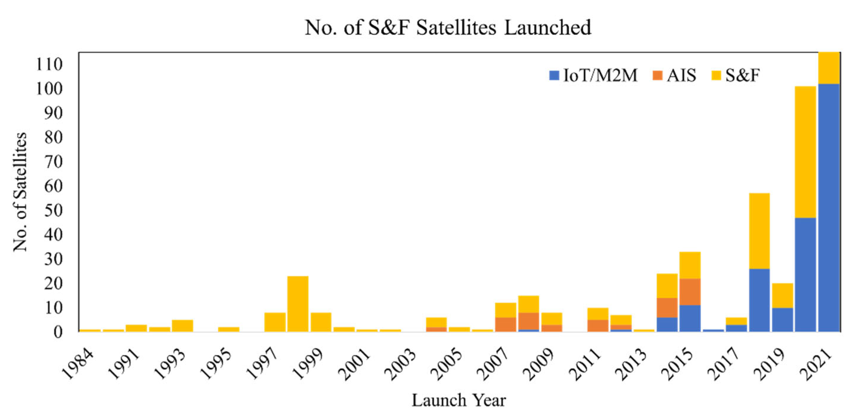
Table 1, and 86% of these satellites were used for commercial communication missions to provide global Internet services and leveraging the Internet of Things (IoT), machine-to-machine (M2M) communications, and store and forward (S&F) missions.
In addition, recent applications of satellite-based S&F systems have enabled achieving IoT/M2M, which are also referred to as satellite IoT (SIoT), and automatic identification system (AIS) applications for tracking ships. At least 18 space startups entered the IoT market in 2018, and an exponential growth in the number of satellites employing S&F for IoT/M2M could be observed from this period in
Figure 1. Most startups plan to launch dozens to hundreds of CubeSats or satellites even smaller than the 1U CubeSat form factor in low Earth orbit (LEO) to provide global coverage and lower latency time in data retrieval [
2].
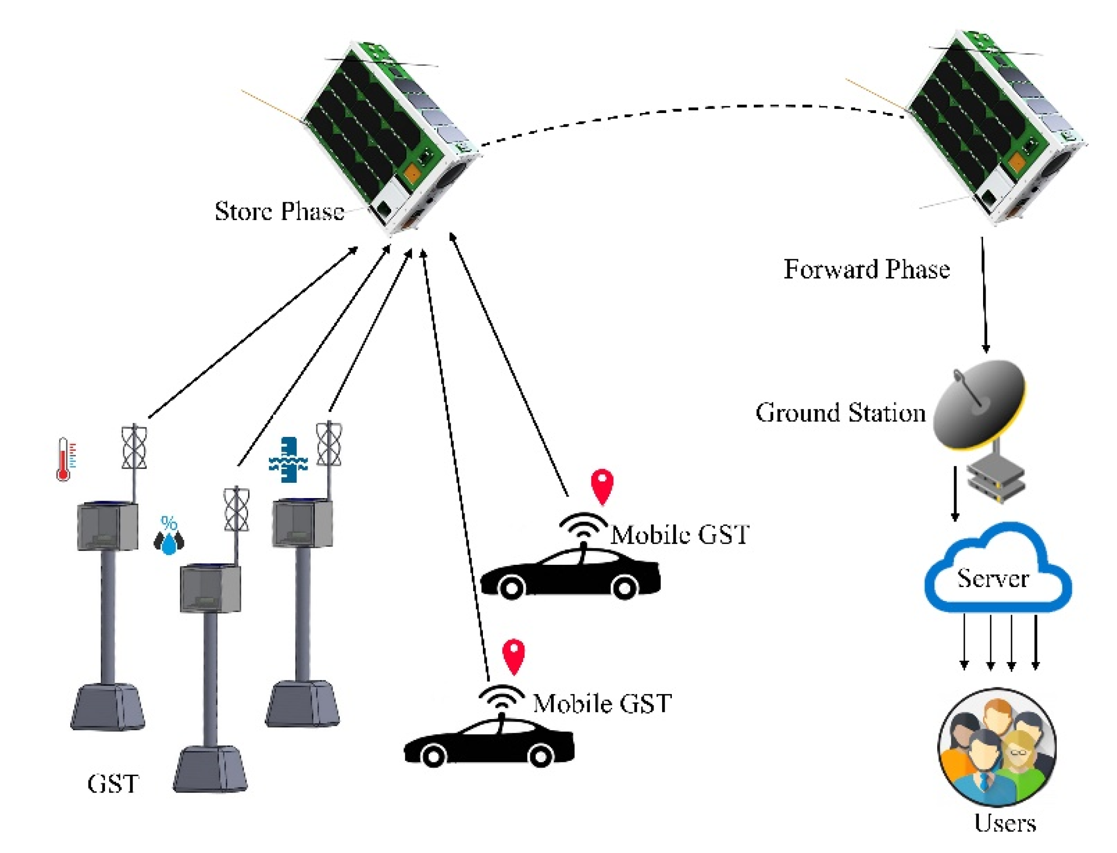
A satellite-based S&F system is a communication technique in which a satellite is used as a gateway for data collection and dissemination. Therefore, the basic principle of operation requires establishing communication between a terrestrial station and a satellite to uplink successfully. The next step could be described as storing data in the satellite through that uplink. Finally, the stored data could be downloaded to another ground station to be distributed or forwarded to its destination [
3]. The time difference between the first and last step indicates the latency time through the operation, and it could be a critical parameter with regards to the application [
4,
5].
Figure 2 shows the illustration for the basic principle of operation of a satellite-based S&F system.
The first proof of concept for the digital S&F communications experiment was carried out in the UoSAT-2 satellite as one of the missions by the University of Surrey in 1984 [
6]. Some notable investments for global coverage using S&F satellites include service providers such as Iridium constellations, Argos Data collection system, and Orbcomm constellations, and they have been operating since the mid-nineties. Although it has been predicted that there will be more than 83 billion IoT connections by 2024 [
7], there are still inaccessible regions by terrestrial networks in most developing countries. According to a report by International Telecommunication Union (ITU) for 2021 [
8], 37% of the total population do not have access to the Internet, and 98% of this population reside in developing countries. Furthermore, it was reported that 84 out of 160 weather stations are still manually operated in Bhutan in South Asia [
9]. The lack of automatic weather stations is observed in other developing countries such as [
10], where the near-surface temperatures and rain levels are expected to significantly alter the water resources, agriculture, energy resources, infrastructure and so on [
11]. As a result, a CubeSat-based SIoT in LEO could offer a solution to several existing and approaching needs [
12], and it could be considerably valuable to retrieve sensory measurements of the critical parameters related to the weather, soil, and water quality from the most inaccessible rural regions. The advantages of leveraging SIoT in LEO, which are not only limited to CubeSats, could be listed below:
Implementation of SIoT applications is promising using CubeSats; however, it is also challenging due to limitations in power budget, available space for payloads and requirements for fulfilling adequate link margin between the satellite and the GSTs. In addition to these constraints, evolving wireless technologies with power efficient communication protocols enabling Low Power Wide Area (LPWA) coverage such as Sigfox [
15], NB-IoT [
16,
17], and LoRa have been studied for their adaptability to be employed for communication between the GST and the onboard payload. LoRa has been implemented as the communication protocol in this study for several reasons, which are explained in the following sections.
LoRa stands for Long Range, and it is a proprietary modulation scheme based on chirp spread spectrum (CSS) technique. Since it can establish communication over long distances, communication protocols for satellites with ground LoRa terminals have been of great interest. In addition, it has low transmission power requirements while being robust against multipath fading and the Doppler effect. Many studies and experiments have been performed for assessing LoRa adaptability in the LEO SIoT. While LoRa performance over long-distance links up to 250 km was tested in [
18], a satellite communication scenario with a Doppler residual frequency deviation of 22.3 Hz was tested in [
19]. Various analyses regarding the performance of LoRa in LEO have also been performed in [
20,
21,
22], and constellation designs using LoRa-based SIoT have been proposed in [
23] for achieving low-latency IoT. Although there are many works in the literature that studied and predicted the expected performance of LoRa transceivers in LEO, many of these studies have not been validated through flight demonstrations. A small number of satellites launched with LoRa mission payloads, including a university satellite project TRICOM-1R that was successfully able to confirm the reception of data in the 920 MHz band over 300 km distance [
24]. Following the design of the TRICOM-2 satellite, JPRWASAT was launched by Rwanda with a LoRa receiver, and the result of this mission has not been published thus far [
25]. Sapienza University of Rome launched WildTrackCube—SIMBA [
26] with LoRa receivers for monitoring the behavior of animals in Kenya. Commercial companies such as Lacuna Space have launched 5 out of a planned constellation of 240 satellites, and Swarm Technologies launched 93 out of a planned constellation of 150 satellites for achieving SIoT using LoRa modulation in the Very High Frequency (VHF) band [
7]. Fossa Systems launched FOSSASAT-1 with a LoRa transceiver that could communicate with their ground module in amateur UHF band, and the on-orbit results are unavailable due to antenna deployment failure. In addition, FOSSASAT-1B had a launch failure; however, it is still planned to launch a constellation of 80 satellites for providing IoT connectivity [
27].
Although many of these technology demonstrations of satellites with LoRa transceivers have been launched, a limited number of publications discuss details of LoRa payload design, on-orbit operation results, capacity, experimental outcomes, and the performance of the LoRa physical layer in LEO. This paper describes how a small satellite platform named KITSUNE has the capability to provide services to multiple developing countries for remote data collection. This paper discusses the implementation of LoRa modulation on a CubeSat and GSTs developed in domestic environments for achieving SIoT. LoRa modulation had been used for communication as it has been studied extensively, and the technology is more viable for ground-to-satellite links. The unique aspects of this study are listed below:
The system model is described with comprehensive details on the design of SIoT payload and the GSTs.
The payload design could be accommodated in a 1-unit CubeSat, and it could be directly plugged into the open-source BIRDS bus developed at Kyutech [
28].
The payload design is software-configurable in terms of data rates and sensitivity of the receiver on orbit.
The capacity of the proposed network is evaluated through several parameters defined through ground testing results, simulations, and on-orbit results.
It fosters the involvement of 11 mostly developing countries while promoting capacity-building in space activities within these countries.
The GST design is open source for any country that aspires to be part of this SIoT mission.
This paper is made of five sections.
Section 2 outlines the satellite mission concept and the definition of capacity in terms of the satellite design. It also includes details of the hardware design for both satellite payload and ground segment including design considerations that were made to be hosted in a CubeSat platform.
Section 3 defines the parameters that are used to assess the capacity of the mission through various tests such as receiver-sensitivity tests and antenna-radiation pattern tests, in addition to estimations for parameters such as communication time between the satellite and GST. The parameters derived in
Section 3 are used to quantify the capacity and coverage of the proposed SIoT system in
Section 4, and the overall study is concluded in
Section 5.
2. Mission Concept
Considering the KITSUNE mission in LEO, the communication time between the GSTs and the satellite could be estimated for a single satellite in orbit. However, the potential capacity of the SIoT mission without limiting to a single satellite could be evaluated based on the constellation configuration, distribution of Ground Stations (GSs) and GSTs, and the communication capability as listed below:
The number of satellites in orbit, number of orbital planes, elevation angle, orbital plane spacing and orbital eccentricity for continuous data reception from GSTs and relaying to multiple ground stations if a constellation is employed considering global coverage and target application scenarios [
29,
30].
The number of GSTs in optimized locations for maximizing ground coverage of each GST [
31,
32].
Number of geographically distributed ground stations capable of downloading the data from the satellites and forwarding it to a database accessible by the users [
33].
Interlink capability of satellites in a constellation to relay the data to ground stations for lower latency in data retrieval from the GSTs [
34].
The uplink and downlink capability of the satellites and the GSTs, which depend on the communication frequency, data rates, transmit power and receiver sensitivities.
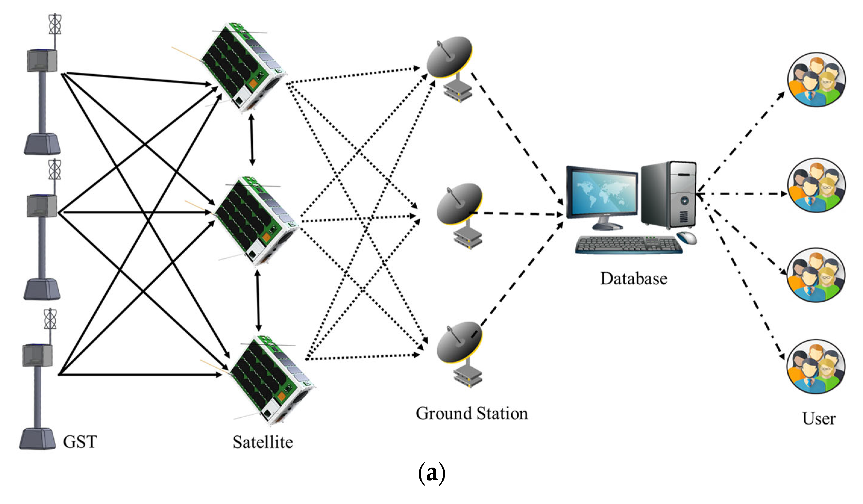
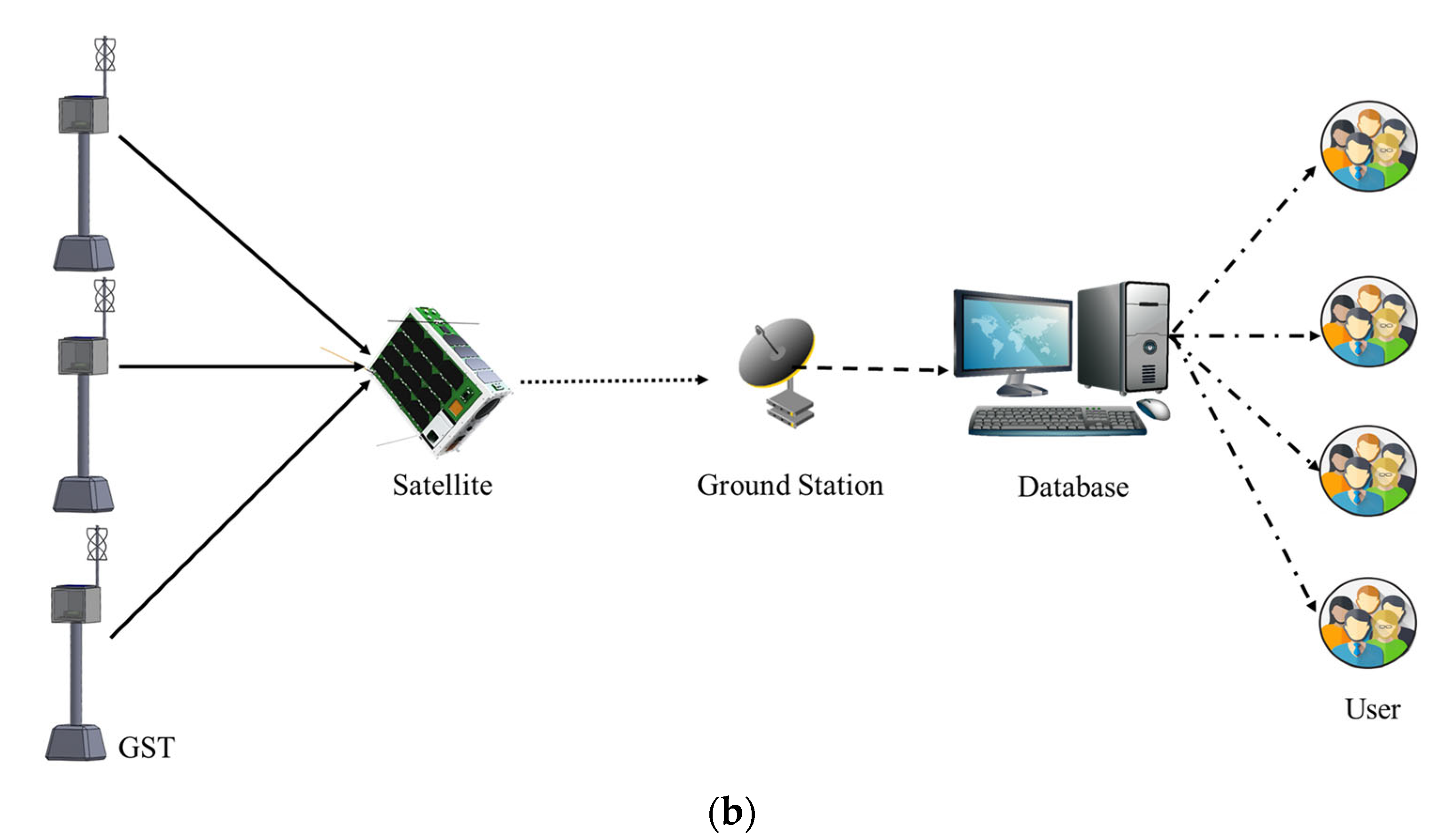
The full capacity of SIoT that provides continuous coverage almost in real time could be realized by using multiple GSTs that transmit the data to a constellation of satellites communicating with each other and distributed ground stations, in order to minimize the latency time. Furthermore, the ground stations forward data to a common database that is accessible to the users as illustrated in
Figure 3a.
In this paper, an SIoT mission considering a single satellite, KITSUNE, with 11 geographically distributed GSTs and one ground station capable of downloading the data is proposed as shown in
Figure 3b. A single satellite is incapable of providing continuous coverage, but it could be employed for delay-tolerant applications (DTA).
The proposed method is targeted towards offering a low-cost solution to developing countries and collaborative capacity-building programs such as the utilization of KiboCUBE, which considers a piggyback launch to the International Space Station (ISS) [
35]. Therefore, the methods for optimizing the coverage performance by using a minimum number of satellites in a LEO constellation as in [
23,
36,
37] are not applicable to this study since it only uses a single satellite at ISS orbit. Furthermore, the variation of the coverage and capacity in different latitudes have been shown through a metric of coverage degree and IoT device density [
36]. Therefore, there are multiple aspects to accomplish the full capacity of an IoT mission considering the space-segment and the ground-segment simultaneously. In this study, the choice of orbital parameters is limited to orbital inclination of 51.6° and altitude of approximately 400 km as in KITSUNE satellite. The idea of the proposed method is not to launch a constellation of satellites to achieve continuous coverage. Instead, it is critical to prove that a CubeSat mission could help to collect data from remote locations in developing countries, which could be a significant step towards capacity building and space utilization as a demonstration mission.
2.1. KITSUNE Mission
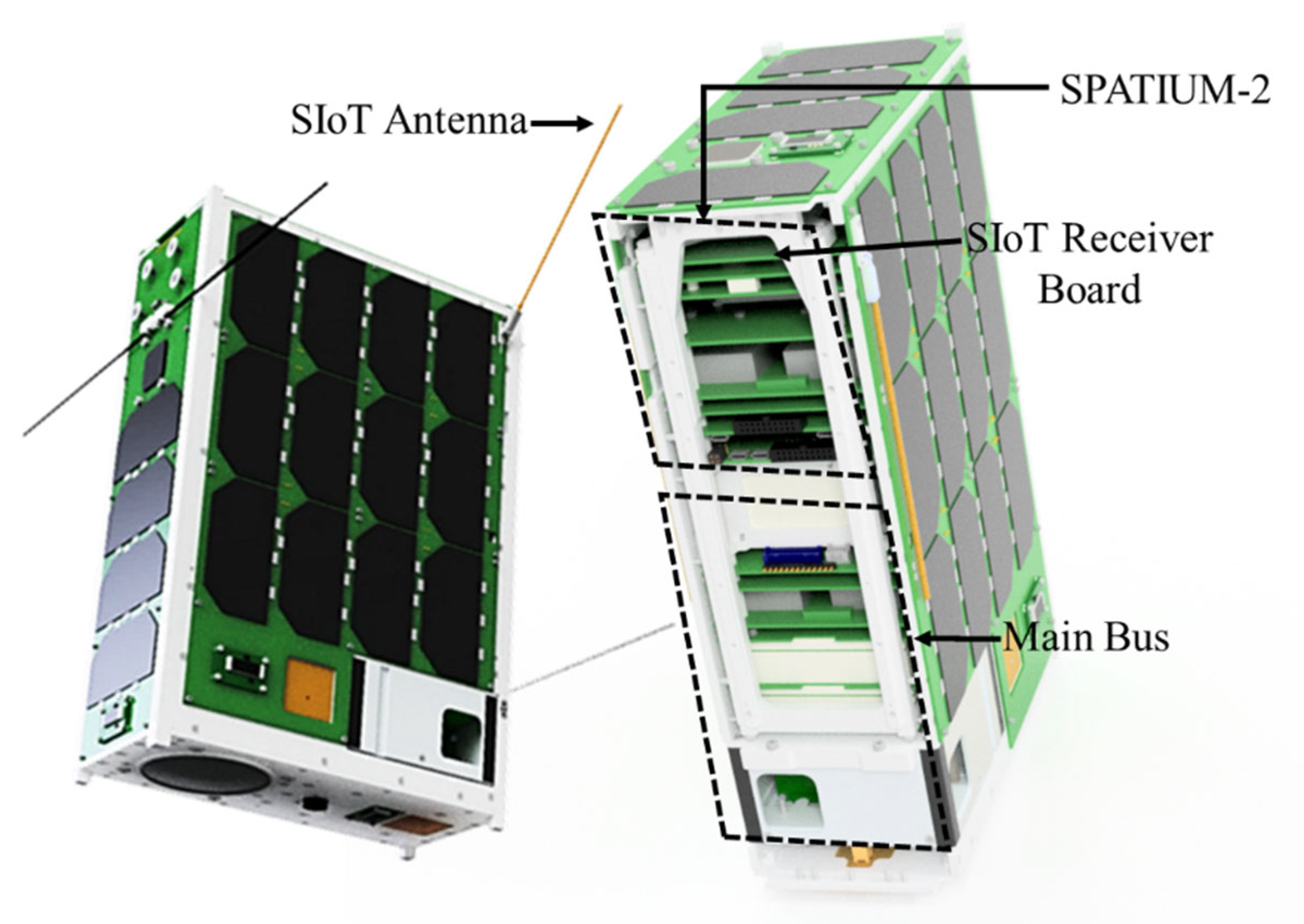
The KITSUNE satellite has dimensions 340.5 mm × 226.3 mm × 100.0 mm and a weight of 7.544 kg, and the internal structure of the satellite is shown in
Figure 4. KITSUNE was launched to ISS on 19 February and deployed on 24 2022. KITSUNE was developed as a dual satellite system; separating the components based on utilization of amateur and non-amateur frequencies. The amateur radio frequencies are selected for 2-unit main bus (2UMB) and 3-unit camera payload, whereas 1-unit SPATIUM-II (space precision atomic-clock timing utility mission) hosts the total electron content (TEC) and SIoT payload while using non-amateur frequencies for communications.
The 2UMB controls the main payload of the Earth-observation mission to capture 5-m class images through amateur radio frequencies. It also provides direct power from its battery to SPATIUM-II, which has its own bus system. In addition, there is no control command from the 2UMB to SPATIUM-II; therefore, they operate as a dual-satellite system housed in the same structure with a common battery. SPATIUM-II is controlled independently by a separate GS in Kyutech through non-amateur radio frequencies, and its SIoT mission is the described with space-segment and the GSTs in this paper.
SIoT Mission
The main aim of the SIoT mission can be described as a demonstration of a CubeSat-based SIoT system for achieving remote data collection and IoT service from GSTs in multiple countries. The mission objectives considering the satellite payload and the ground segment are listed below:
Development of SIoT payload using COTS components.
Development of low-cost and lower power GSTs, which could be fixed or mobile stations that could collect a wide range of sensor data.
Collaborative development of GSTs to employ the most suitable sensor configurations in developing countries and deploy GSTs in remote locations around the world.
Remote data collection of sensor data using KITSUNE and distribution of data using an online database management system developed at Kyutech.
Human capacity building, knowledge transfer and promotion of international collaboration in developing countries for satellite-based missions.
In order to achieve the mission objectives, the technical mission requirements for the satellite payload segment were determined as:
The payload shall have multiple channels to receive data from various GSTs simultaneously.
The SIoT receiver shall have sensitivity close to ideal sensitivity, the permissible sensitivity deviation should be less than 10 dB.
The receivers shall be able to operate in two frequency bands (400 MHz and 433 MHz).
The receiver modules shall be reconfigurable on-orbit in terms of spreading factor (SF), coding rate (CR), bandwidth (BW) and center frequency (CF).
The payload shall be accommodated in a 1-unit CubeSat with current consumption of the receiver less than 250 mA to meet the available power budget of a 1-unit CubeSat.
The payload shall be able to operate in the space environment.
2.2. Payload Design
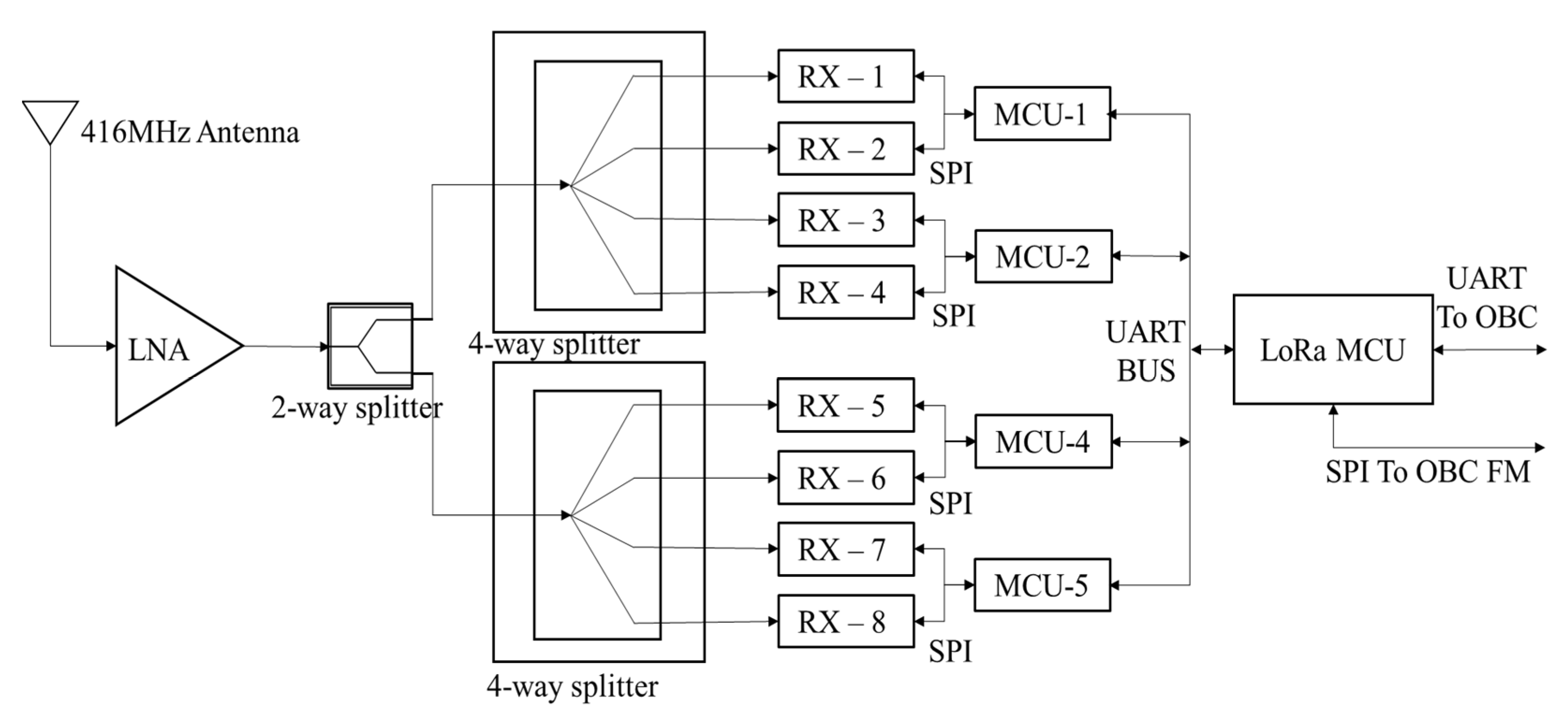
SIoT mission payload has eight LoRa receivers to ensure data reception from at least eight GSTs simultaneously. Each pair of these receivers is controlled and configured by one receiver microcontroller unit (MCU) using serial peripheral interface (SPI) communication protocol. Four of these receiver MCUs are in turn controlled by the main mission MCU, and the block diagram of the payload is shown in
Figure 5.
The receivers could be remotely configured even in orbit, allowing upgrades and optimizations for the execution of the SIoT mission. In addition, the data rates and center frequencies of each of these receivers with a resolution of 1 kHz can be configured remotely by sending an uplink command from the ground station, maximizing the capabilities of in-orbit demonstrations. All the receivers share the same monopole antenna with a wide bandwidth of 50 MHz tuned at a center frequency of 416 MHz.
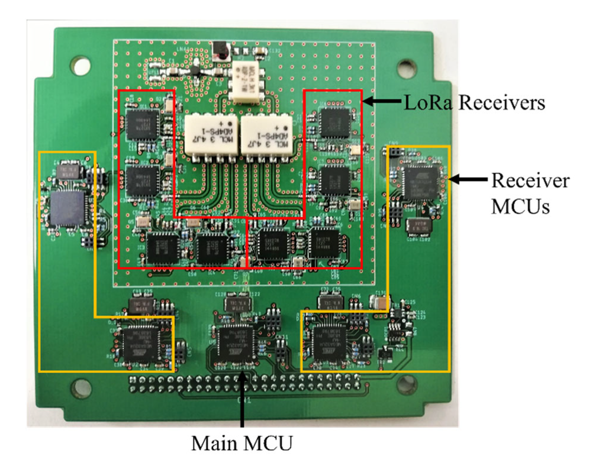
The signals received from the antenna are firstly amplified using a low noise amplifier (LNA) with a gain of 22 dB. The signal passes through a two-way splitter and further through a four-way splitter until it reaches individual receivers. The design is optimized to compensate for the 10 dB losses in the splitters by the gain of the LNA. The receivers can detect signals as weak as −135 dBm from the ground. In addition, the PCB design of the payload is compatible with the open-source BIRDS Bus [
28] for 1-unit CubeSat developed at Kyutech following the backplane type interface, which uses a 50-pin connector as shown in
Figure 6.
SX1278 LoRa transceiver chips developed by Semtech have been used as onboard receivers, and these chips have flight heritage from the BIRDS-3 LoRa demonstration mission (LDM), where the basic operation was confirmed for more than 2 years in orbit. In the LDM mission, two RFM98 modules with SX1278 chips, one as a transmitter and another as a receiver, were connected in a PCB with a 20 dB attenuator between them to avoid emission outside of the satellite as mandated in the frequency license application process. When the mission was executed, a 10-byte data packet was sent 20 times from the transmitter to the receiver, and during this transmission the current consumption and temperature of both the transmitter and receiver were recorded to detect anomalies. The received data packets were checked using CRC bytes, and the recorded data were downloaded to perform analysis on the ground [
28].
The patented LoRa modulation technique using the LoRa transceivers can achieve a sensitivity of over −148 dBm according to the datasheet [
38]. The transmission range and the data rates are determined by bandwidth and the SF. A combination of lower SF and higher BW allows higher data rates with shorter transmission range while higher SF and lower BW provide a longer range with reduced data rate. In addition, these transceivers could be a suitable option for CubeSat-based SIoT data collection systems due to high interference immunity and low power consumption. Several commercially available complete modules such as RFM98 have been designed by companies such as HopeRF using SX1278 transceiver chips, and these modules have a predesigned matching circuit for both input and output. In KITSUNE, the matching circuit was entirely designed by the team to optimize the PCB design while improving the RF performance. Since the payload board requires us to employ “receive-only” capability from the GSTs, the input matching circuit was optimized and designed according to the datasheet recommendation for reception only. All the components used for the payload design are COTS components and were chosen for their ease of availability, affordable costs, and their performance. The power consumption of the receiver payload is 0.84 W and 1.26 Wh per orbit. In addition, the specifications of the receiver payload board are detailed in
Table 2 below.
The satellite has three modes of operation for SIoT mission in orbit as listed below:
Instant mode: The mission payload is turned on instantly over a ground station using an uplink command. The mission duration is specified in the command, and the receivers are turned on for that specific period.
Target Mode: The reservation commands are uplinkeded to the satellite to turn on the mission payload over targeted locations as the GST network countries. These reservation commands can be decided based on satellite time and TLE, and a maximum of 10 reservation commands can be stored in the satellite.
24-h Mode: The mission payload can be turned on for 24 h continuously, and the receivers are always in the active listening mode.
The operation and performance of the integrated flight model (FM) were tested in various emulated space environment conditions in order to demonstrate the satellite is able to operate properly in LEO. Fault mode analysis of each subsystem and SIoT mission were also performed during the satellite development process to identify possible causes of failures and contingency plans were prepared to make the system tolerable to these faults.
2.3. Ground Segment
The requirements for the GSTs are stringent as they must be placed in remote locations inaccessible by terrestrial communications. Therefore, the GSTs are required to be simple, robust, and standalone devices that can be powered by solar panels and batteries. The requirements for GST are listed below:
The design shall be capable of incorporating most kinds of commercially available sensors.
The structure shall be able to encompass antenna and solar panels externally, protect internal elements and withstand harsh temperature ranges.
It shall be placed at an adequate height of approximately 1.5 m above the ground for additional protection.
It shall be able to operate continuously and have a low power consumption (<5 Wh/day). GSTs should have standalone operating power using low-efficiency solar cells and commercially available rechargeable batteries.
It shall transmit sensor data to the satellite with an adequate link margin.
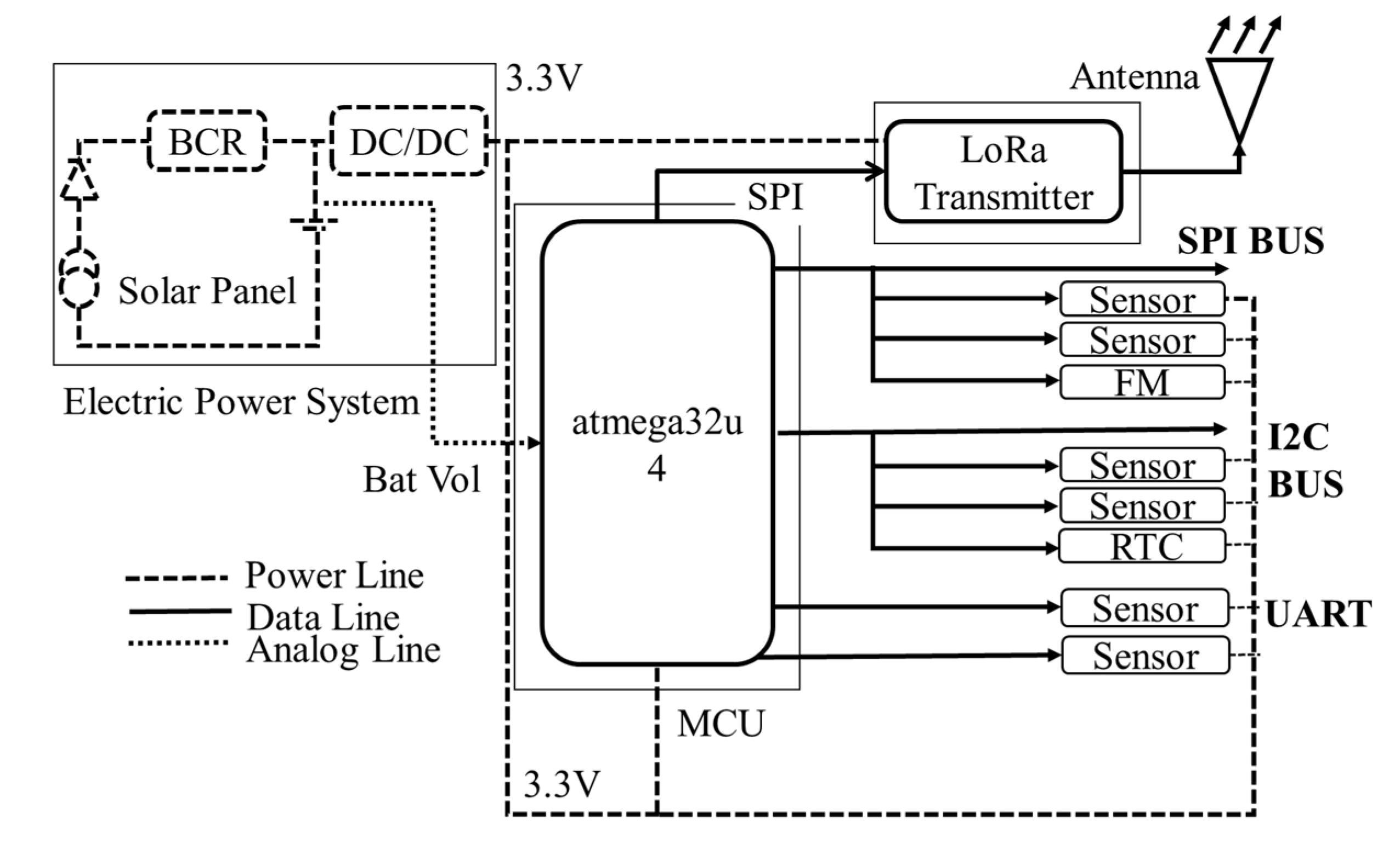
On the ground segment, there are two types of GST designs such as fixed GST that could be placed in any remote place and mobile GST that could be placed on moving vehicles such as public transport. The system design of the fixed GST is guided by the block diagram shown in
Figure 7.
As illustrated in
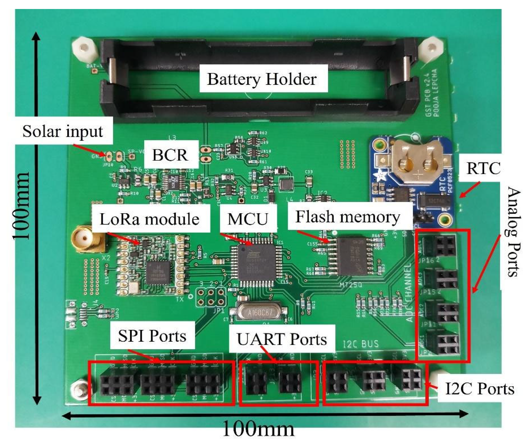
Figure 8, a wide range of sensors could be integrated with the MCU using any of the three-serial data transmission formats. Inter-integrated circuit (I2C), UART, SPI, and analog pins produce a universal sensor port. In addition, the sensors are directly plugged into ports that connect to the MCU, and the collected sensor data is time stamped using a real time clock (RTC). Furthermore, they are transformed into data packets before being transmitted through an antenna via LoRa transmitter. The data packets are also stored in the flash memory (FM). The electrical power system (EPS) of the conventional sensor nodes is typically substantial, owing to their complexity and considerable power requirement. While the EPS in the proposed method is simple and consumes less power to operate, it also comprises low-efficiency, outdoor-grade solar panels, a battery charging circuit (BCR) and a Li-Ion rechargeable battery. The detailed GST design has been explained in [
39].
The fundamental advantage of this system is design simplicity, compact size, robustness, and the ability to operate in harsh environments. Furthermore, another additional advantage is the ability to be installed in any required location without relying on on-ground infrastructure and terrestrial communication networks. The PCB design of the GST is shown in
Figure 8.
The antenna used for the GST is a right hand circularly polarized quadrifilar helix (QFH) antenna. The antenna was designed using the guide mentioned in [
39] for 433 MHz using COTS materials. The standards for electrical enclosures are classified and rated based on the degree of protection provided against dust, water, and other intrusions by the International Protection (IP Code) Marking also known as IEC standard 60,529 [
40]. The MCUs and sensors are enclosed within an IP66 housing that provides complete protection against dust and water while allowing the GST to be placed in remote terrains vulnerable to varying climatic conditions throughout the year. In addition, the specifications of the GST boards are detailed in
Table 3.
The basic mode of operation for GSTs is to sample and transmit sensor data in real time. In addition, the power consumption of the GST is minimized to achieve the power budget for continuous operation with low-efficiency solar panels and rechargeable batteries.
The data packets collected by the satellite from GSTs around the world are downloaded and parsed based on GST ID through a common database. To achieve this, the database is designed to accept the data in standard file formats—either tab separate (TSV), comma separated (CSV) or text (TXT). From the parsed information, data will be encoded in the database through an online webpage by the ground stations, which receive the data. A dedicated user account is provided for each country for data encoding, access, and download. While all data could be accessed by an admin user account, the dedicated user account is restricted to access only for the GSTs of the relative countries. The data collected from the GSTs of other countries are not accessible to anyone else except the country that transmitted the data. To facilitate data sharing, the country could access their own data in the database, and reports could be generated based on their selected data in TSV, CSV or TXT format.
3. Coverage and Capacity Evaluation
To derive the coverage and capacity of SIoT using the payload design and the GST, Equation (1) is used to estimate the data that can be collected per day by KITSUNE.
Data per day is estimated with the communication time between satellite and GST in minutes in a pass τ(i), the number of GSTs visible per day nGST, the number of bytes received per minute B, the ratio of meaningful bytes to total bytes in a packet β, the efficiency factor that incorporates the overall efficiency reduction due to the factors such as performance dependence on temperature and the Doppler effect. These parameters are described in the following subsections that includes overall implementation plan for the mission, the design of the satellite and the GSTs, and the communication protocols between them.
3.1. Communication Time between the Satellite and GST(τ(i))
The communication time τ(i) between the satellite and the GST depends on the link budget, and the link budget depends on the sensitivity of the receiver, elevation angles, antenna gains and losses such as free space path loss (FSPL), polarization loss, and ionospheric loss. These parameters are first determined through the ground tests using the designed payload and GST, and the communication time is derived using the parameters.
3.1.1. Antenna Radiation Pattern
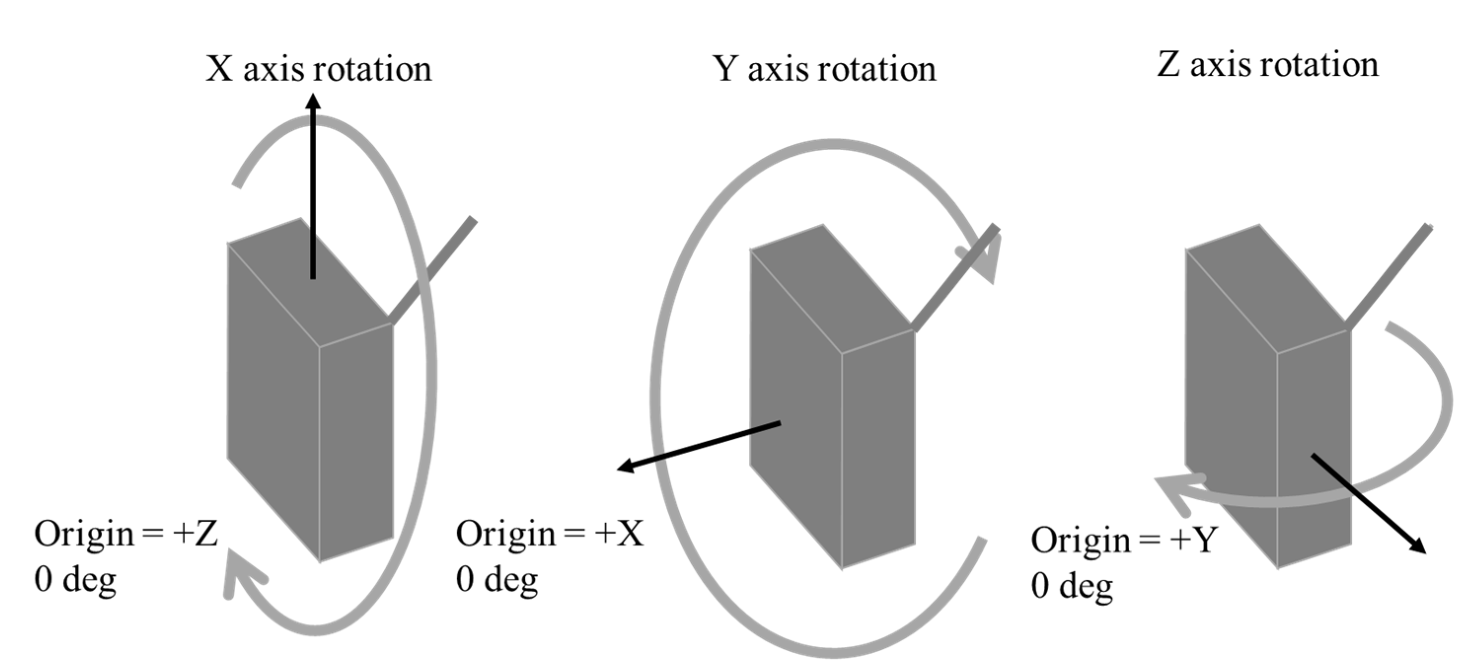
The radiation pattern of the receiver antenna was measured in the anechoic chamber tests. The antenna radiation pattern was measured for three planes such as X-Y plane, Y-Z plane, and X-Z planes, and in each plane for vertical and horizontal orientation of the reference antenna.
Figure 9 shows the rotation axis of the antenna for determining the antenna radiation pattern.
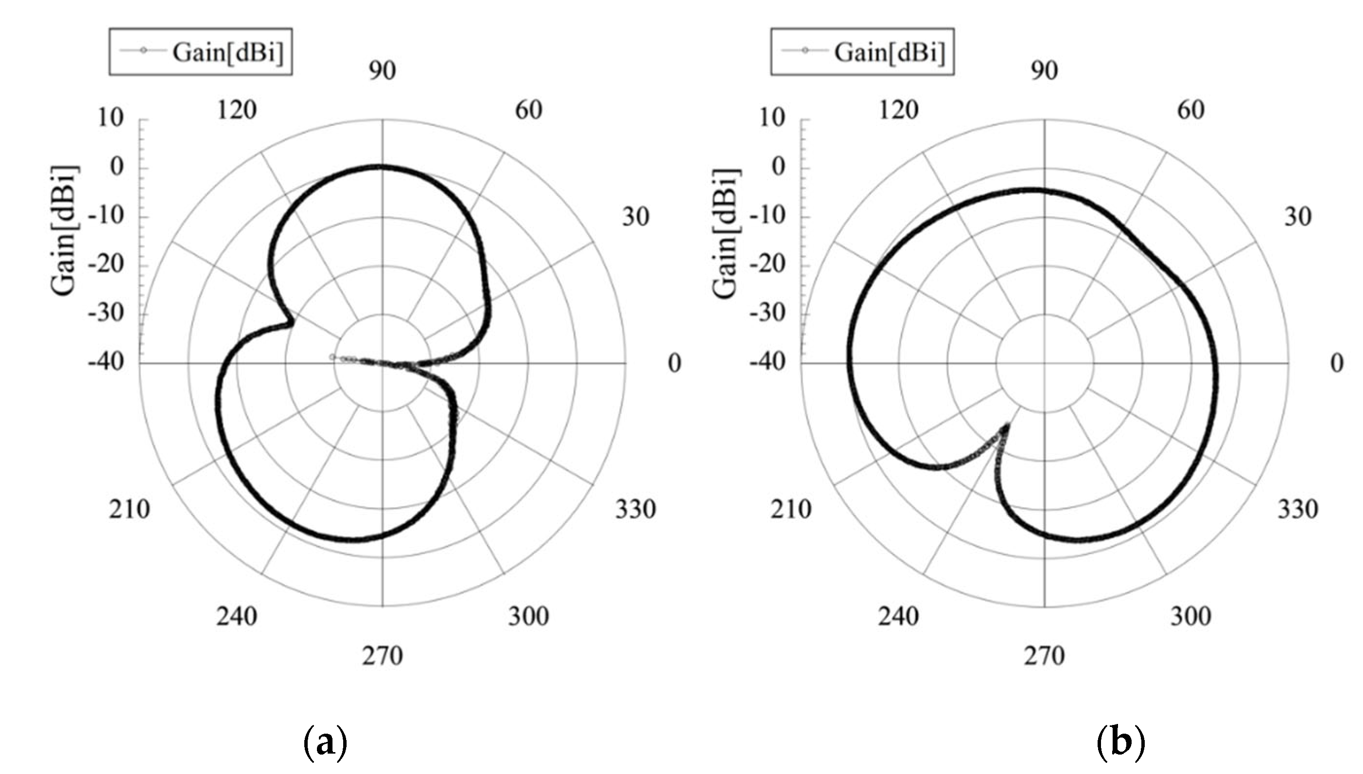
The maximum gain of the receiver antenna integrated together with the satellite body was 0.27 dBi for 400 MHz and 0.36 dBi for 433 MHz as in
Figure 10.
3.1.2. Receiver Sensitivity
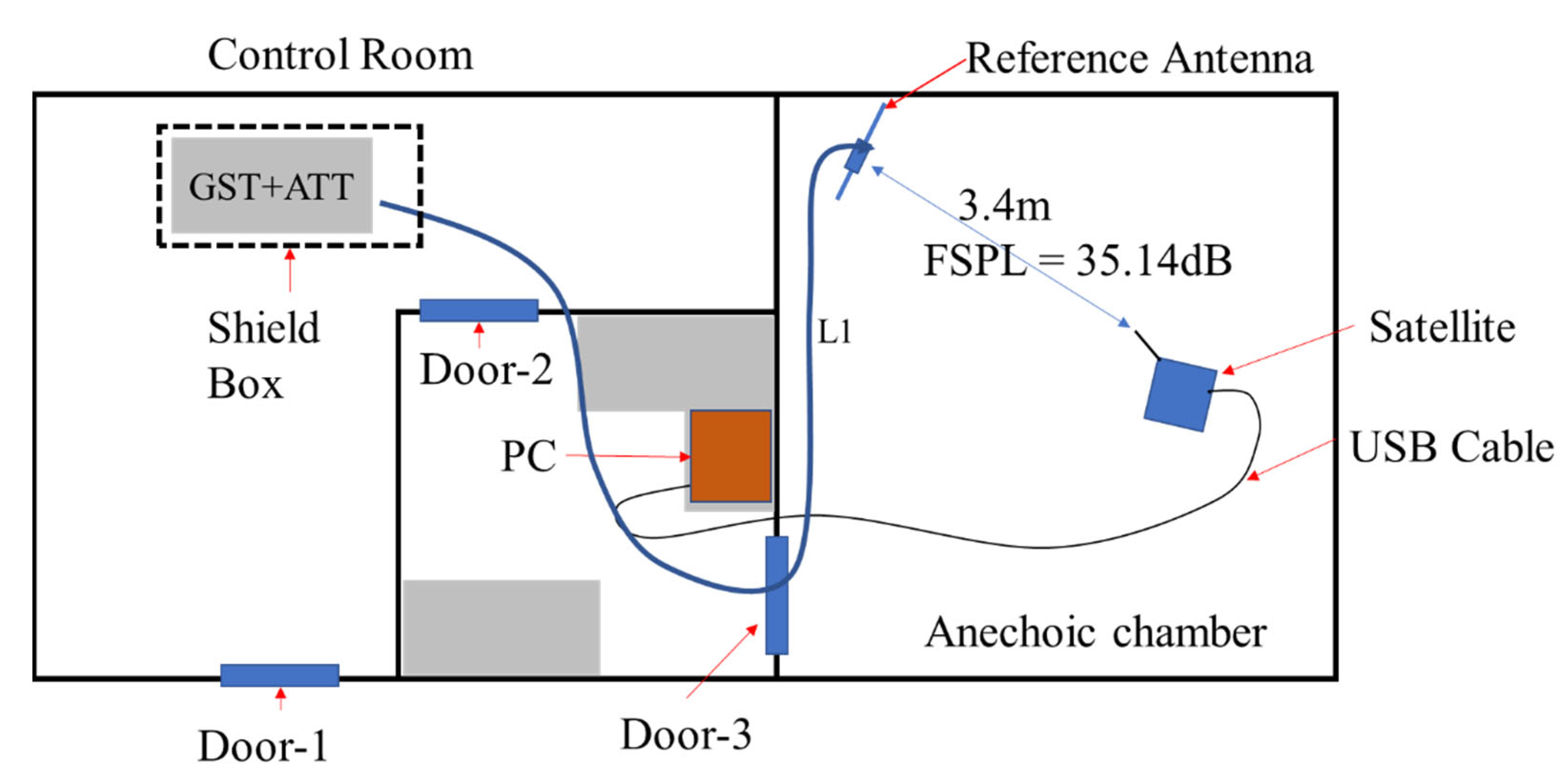
Theoretical receiver sensitivities up to -148 dBm can be achieved with SX1278 modules according to the datasheet; however, the actual receiver sensitivity could be less than the initial design parameters. To determine the functional receiver sensitivity of the produced subsystem, communication tests between the integrated satellite operating at nominal mode and the GST were performed in the anechoic chamber, and the test setup is shown in
Figure 11.
The GST was placed inside the shield box outside the control room to reduce the effect of possible leakage from the GST LoRa transceiver to the payload receiver. A reference antenna with a known gain (G1) was placed 3.40 m away from the satellite, which was connected to the GST using a cable with a cable loss of L1. The GST transmitted data packets to the satellite continuously, and the data reception was recorded on the satellite memory while monitoring through the serial monitor connected to the receiver payload. In addition, it was routed to the control room using a USB cable and attenuators (ATT) were added to the GST side until the receiver payload could no longer receive the data packets. The success rate was calculated by checking whether correct data packets without byte errors were received at the receiver side. The sensitivity was taken for the attenuation for which at least 60% of the overall packets were received correctly.
The GST transmitted an 18 dBm signal using a reference antenna with a maximum gain of 2.15 dBi. The cable loss L1 is determined to be 22.04 dB, and the FSPL was calculated as 35.14 dB. The Equation (2) was used to measure the sensitivity of the receiver, and all terms are given in decibel (dB) scale in the equation below.
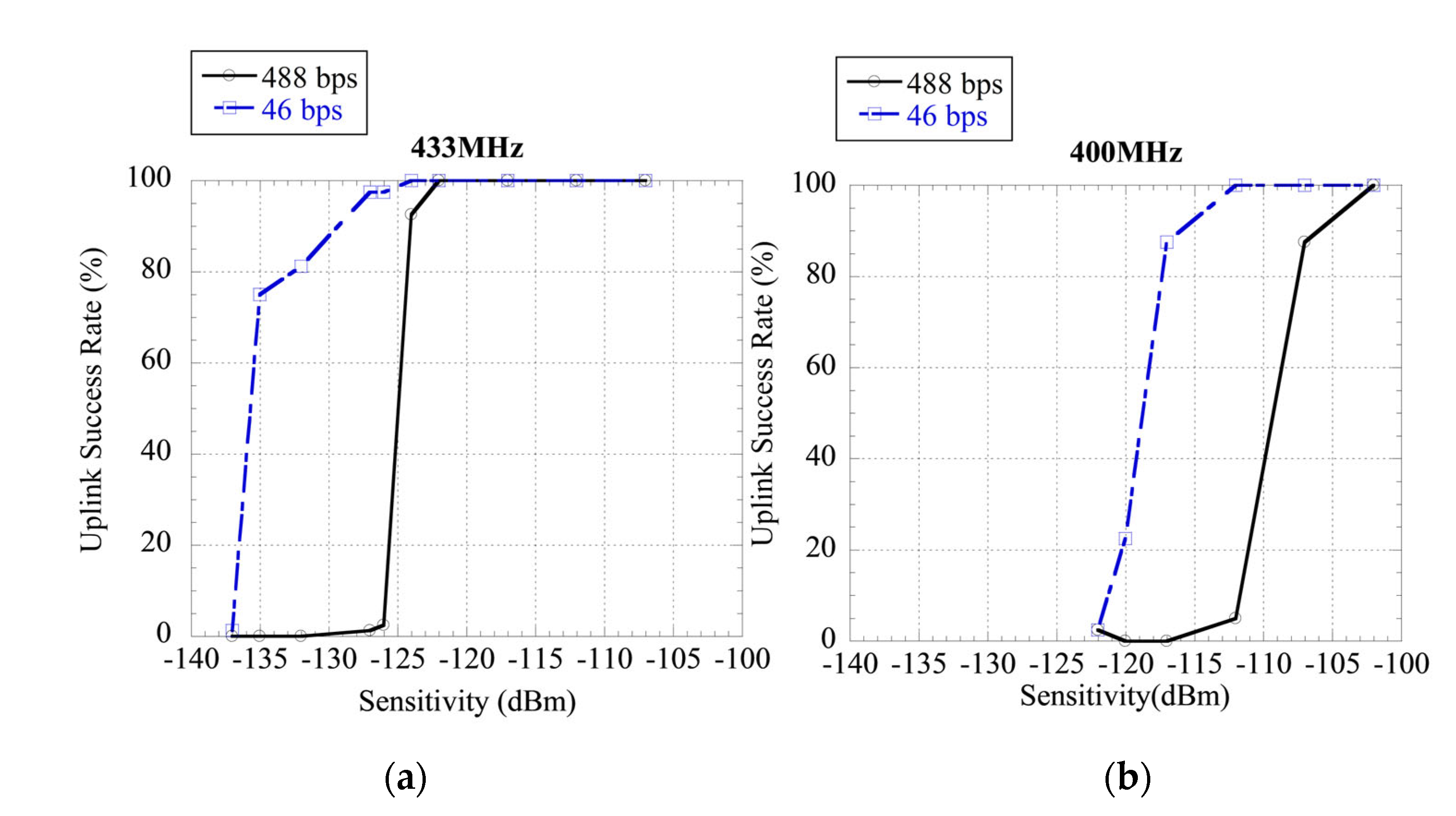
Various combinations of SF and BW were tested for achieving different data rates and receiver sensitivities by the same setup. As a result, the optimal settings obtained balancing the date rate and the sensitivity are determined to be with SF 12, BW 31.25 kHz, and CR 4/8. The resulting data rate is 46 bps. Additionally, a receiver with SF 8, BW 31.25 kHz and CR 4/8 resulting in a data rate of 488 bps was also tested to understand the relationship between data rate and sensitivity. The results of the tests are shown in
Figure 12.
The minimum measured sensitivity considering 60% successful data reception is −118 dBm for 400 MHz, and −135 dBm for a data rate of 46 bps. The measured sensitivity is 26 dBm less for 400 MHz and 9 dBm less for 433 MHz compared to the ideal sensitivity that could be achieved at these settings, which is −144 dBm. According to these results, the reduced sensitivity could be attributed to deviation in performance of the electronic components from designed parameters due to mismatch in circuit blocks and non-ideal components and internal EMI of the satellite. Furthermore, the additional deviation for 400 MHz could be attributed to environmental noise. Although the satellite was placed inside the anechoic chamber that can provide attenuation of 100 dB in the 400 MHz range according to MIL STD 285 standards, noise peaks from outside the chamber were observed in the spectrum analyzer captured by the dipole antenna. These noise peaks were not observed in the 433 MHz range, and the receiver sensitivity at 400 MHz is expected to be similar to 433 MHz when the satellite is in orbit.
The measured sensitivity for 433 MHz at 46 bps is considered adequate for communication with the satellite in orbit. Higher sensitivities can be achieved using lower data rates, but the data transmission time increases as well. For instance, decreasing data rate from 46 bps to 11 bps, the transmission time increases from 3 s to 14 s. As a result, data transmission for longer periods would result in higher power consumption for the GSTs, and the data packets could be affected by doppler shift rate and the monopole antenna rotation with tumbling satellite.
3.1.3. Link Budget Calculation
The measured sensitivity is accounted to calculate the link budget in orbit, considering the satellite orbit as 400 km and FSPL at elevation angles of 10°, 20°, 30°, 40°, 60°, 80° and 90°. The transmit power of 20 mW is used since in most countries with this power, a license is not required to transmit with 433 MHz frequency an Industrial, Scientific, and Medical (ISM) band. The maximum permissible transmit power is determined by the radio communications regulation of each country. Using this sensitivity, the link budget is calculated considering the losses detailed in
Table 4, both on the satellite side and the GSTs.
The link margins for varying elevation angles in the 400 km orbit are detailed in
Table 5. The antenna gain variation of the GST for each elevation angle of the satellite is considered for the link margin calculations.
According to the link margin calculations, a successful uplink of sensor data from the GST to the satellite can be achieved for elevation angles greater than 33 degrees. The communication time between the satellite and the GST can hence be determined for satellite passes with elevations greater than 33 degrees with Equation (3).
τ < 33 is the time in minutes when the elevations are less than 33 degrees. Satellites in LEO have an orbital period of approximately 90 min with an average of 10 min ground pass for at least four times in a day. To derive actual communication time between KITSUNE and the GSTs, the simulation for satellite orbital path is performed in
Section 3.2.
3.2. Number of GSTs Visible per Day (nGST)
The GSTs for the KITSUNE SIoT mission are simultaneously being developed in 11 different agencies/institutions predominantly from the developing countries. The participating countries are part of the BIRDS Ground Station Network (GSN) that was initially formed to support the missions of BIRDS constellation of satellites [
41]. The countries that are a part of the GST Network along with the application are explained in
Table 6. Most of these participating countries have significantly limited access to space technologies with highly constrained space programs.
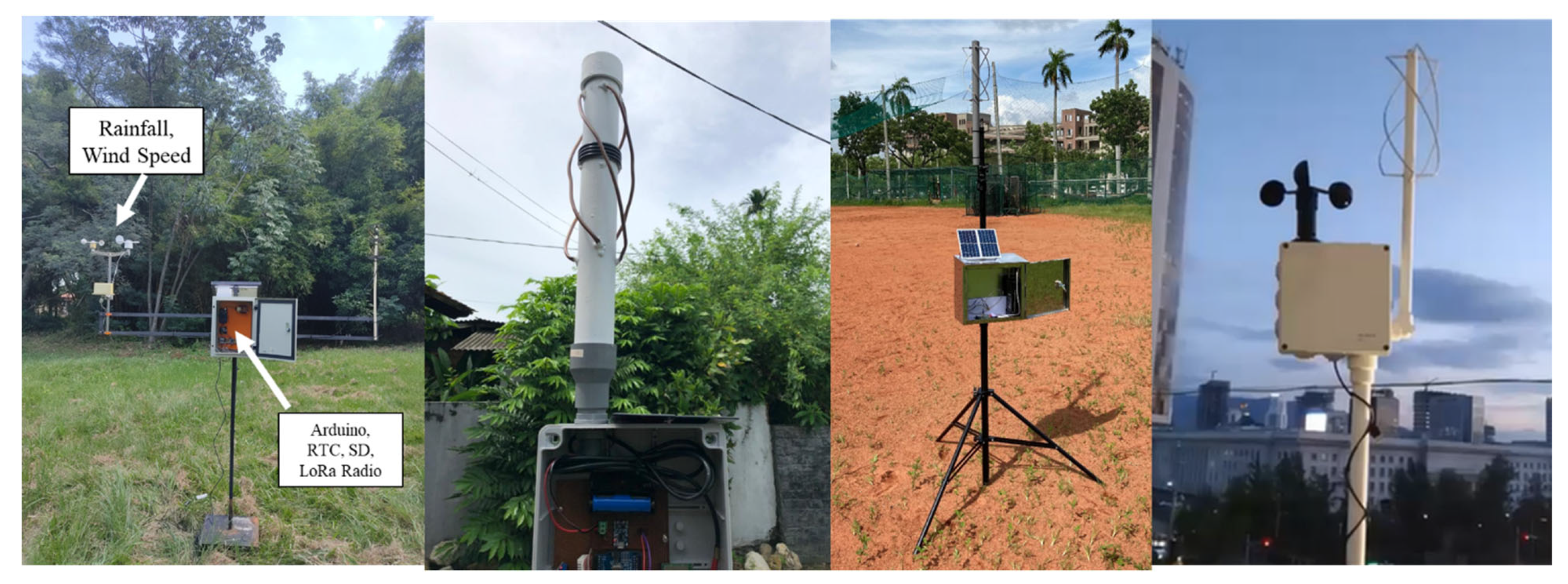
Currently, one GST is being developed in each of these countries (except Paraguay with two GSTs) but prospects for multiple GSTs for providing more coverage are underway. The GSTs developed in some of these developing countries are shown as an example in
Figure 13.
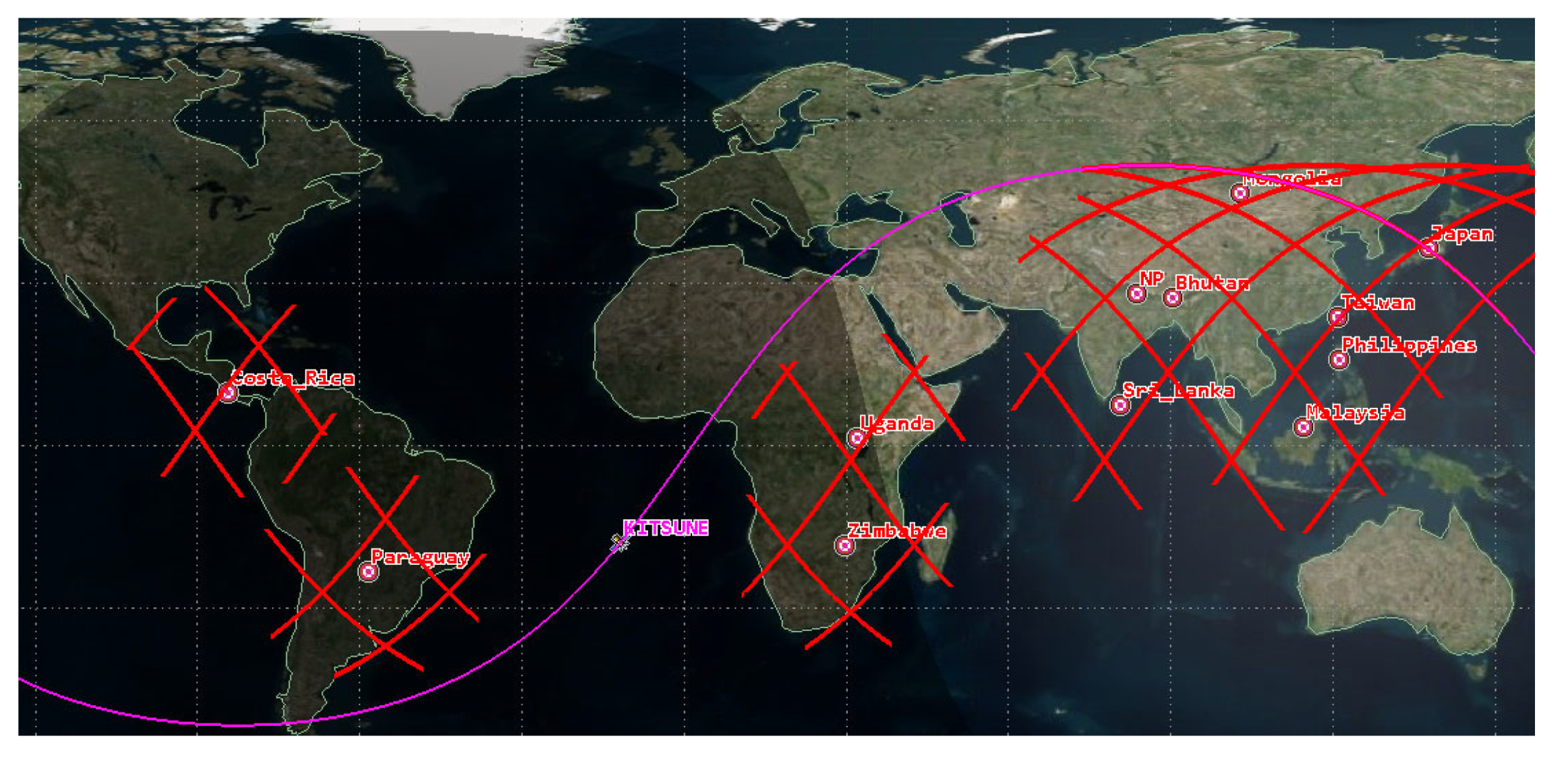
The orbital path of the KITSUNE is simulated for 24 h in STK software, and all possible passes for GST network countries participating in the SIoT mission are generated. On average, each country has five passes per day while each pass varies between four minutes to ten minutes. The path of the passes is shown in
Figure 14.
In
Section 3.1 a positive link margin is derived for elevations greater than 33 degrees. According to the simulation, there is at least one pass per day with elevation greater than 30 degrees in each country. For delay-tolerant applications, collection of data once per day is tolerable for these kinds of applications.
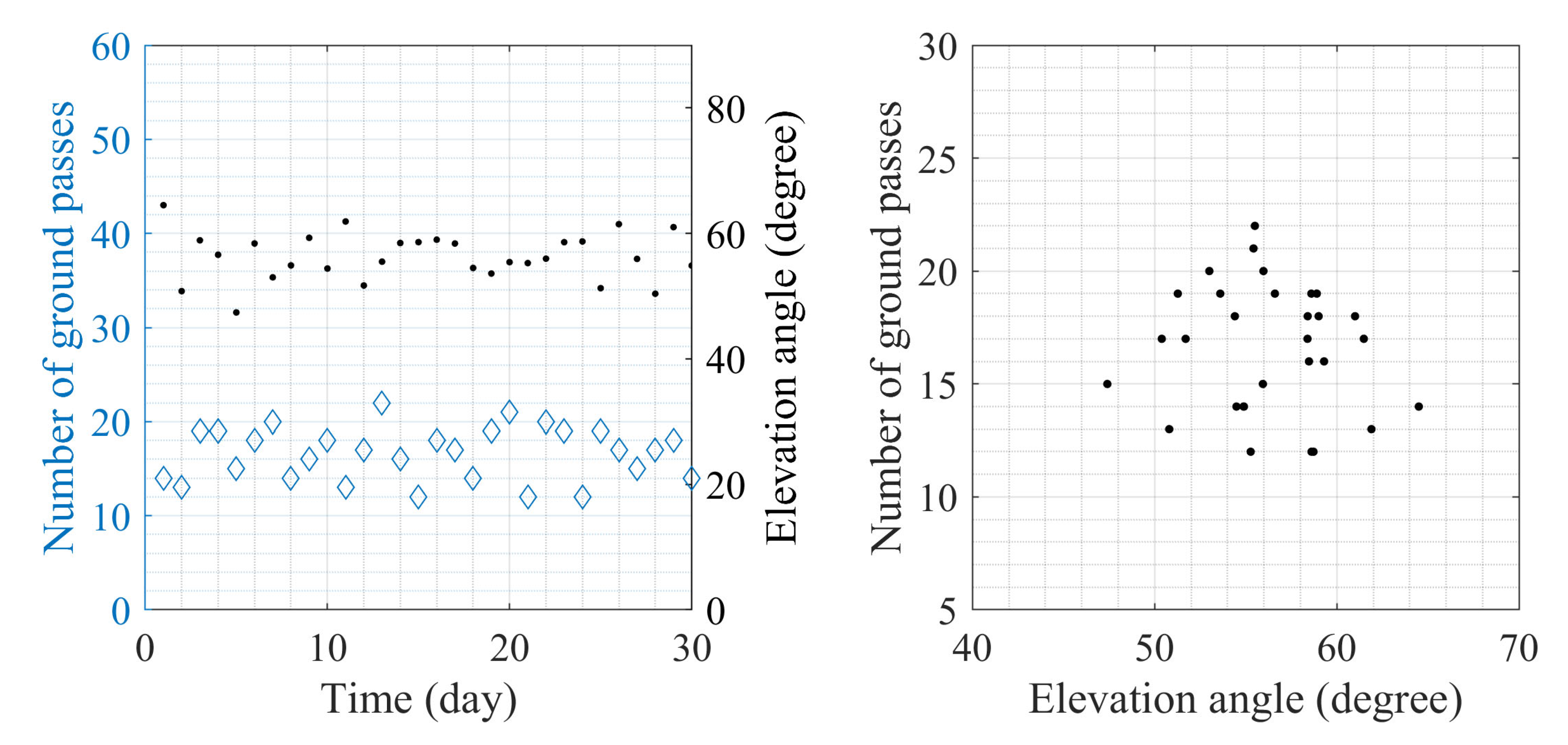
For in-depth analysis of number of visible GSTs for a longer period, the orbital path was simulated for one month (31 days) for elevation angles greater than 33 degrees. The result of the simulation is summarized in
Figure 15. In summary, the number of GSTs that are visible for elevation greater than 33 degrees ranges between a minimum of 12 passes to a maximum of 22 passes in a day and an average of 16 passes for the entire period. The average elevation angles per day varies between 47 degrees to 64.50 degrees and an average of 56 degrees for the whole period.
The number of visible GSTs in a day, nGST, derived from the simulation results is taken as 16 and the average elevation is taken as 56 degrees. Assuming a proportional elevation increment during a satellite pass of 10 min of 56-degree elevation, using Equation (4), the communication time τ(i) between satellite and GST is calculated as approximately 4 min.
3.3. Number of Bytes per Minute (B)
The number of bytes
B that the SIoT receiver payload can receive depends on the programmed algorithm for data reception. The receivers are programmed to receive data packets with a maximum packet length of 32 bytes. The receiver MCUs store five packets of 32 bytes of data temporarily from each receiver before forwarding it to the main mission LoRa MCU, using universal asynchronous receiver-transmitter (UART) line every one minute. The number of bytes the satellite can receive per minute is given by Equation (4).
The number of bytes that the satellite can receive depends on the number of packets the receiver can transfer to MCU per minute, np, the number of bytes in a packet, nB and the number of MCUs, nMCU. Therefore, the number of bytes B that can be received in one minute is approximately 1280 bytes.
The LoRa MCU stores the received data in a 1 Gbit flash memory in the OBC/EPS board based on the day number, and each day 64 kB of data storage is assigned in the flash memory. This design enables ease of data download after the satellite is deployed in orbit. This MCU also communicates with the onboard computer (OBC) using the UART protocol. The collected data will be downlinked using another transceiver in the licensed UHF band with a data rate of 4800 bps.
3.4. Ratio of Meaningful Bytes to Total Bytes in a Packet (β)
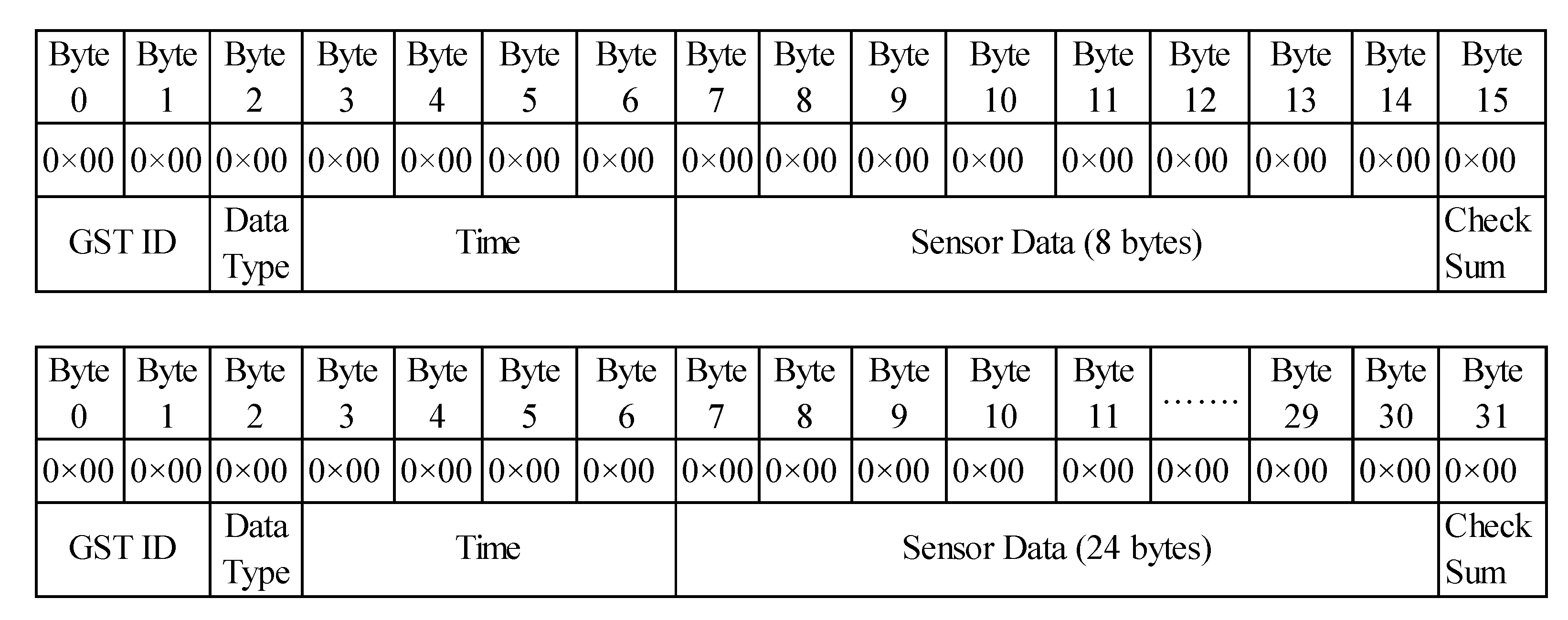
Since many GSTs are expected to be deployed in various parts of the world, it is imperative to identify the data source as the origin country and the location of the GST. As a result, a data packet format has been standardized for all GSTs, which includes GST ID, data type, time of data collection and sensor data. Two bytes are assigned for GST ID, and the first byte is for country identification. The second byte is used when there is more than one GST in a country, and it would be identified by using the second byte. The data type specifies what kind of data and how many kinds of data are uplinkeded in the packet. Four bytes are assigned for timestamp, which is the time at which the sensor data was recorded, and it should include seconds, minutes, hour, day, month, and year. Each country can choose whether they want to send data with either short or long data packet format. The optimal data packet length is set to 32 bytes since longer data transmission time consumes more power, and the data packets can have errors due to doppler shift rate and unstable attitude of the satellite. A checksum byte is assigned at the end of the packet to ensure the satellite received the correct packet. The packet formats for GSTs are shown in
Figure 16.
The ratio of meaningful bytes to the total number of bytes can be deduced from Equation (5) that considers only the bytes that contain the time and sensor data.
3.5. Efficiency Factor (ή)
The efficiency factor is introduced in the equation to include the impacts of temperature and the Doppler effect on the reception capability of the designed system. The efficiency factor is derived using Equation (6).
The efficiency factor, ή depends on the efficiency factor due to temperature impact, ηT and the efficiency factor due to the Doppler-shift-impact mitigation method, ηD. The approach of determining the efficiency factors for the proposed system are described in the following subsections.
3.5.1. Efficiency Factor due to Temperature (ηT)
The effects of temperature variations on LoRa modulation have been tested and found to reduce the received signal strength when the ambient temperature increased in [
42,
43]. Inverse correlation between low temperatures and signal-to-noise ratio (SNR) was observed in [
43], but extensive tests for low temperatures have not been performed, especially in the space environment. To deduce the impact of temperature on the data reception quality, an experiment was performed to derive the efficiency factor.
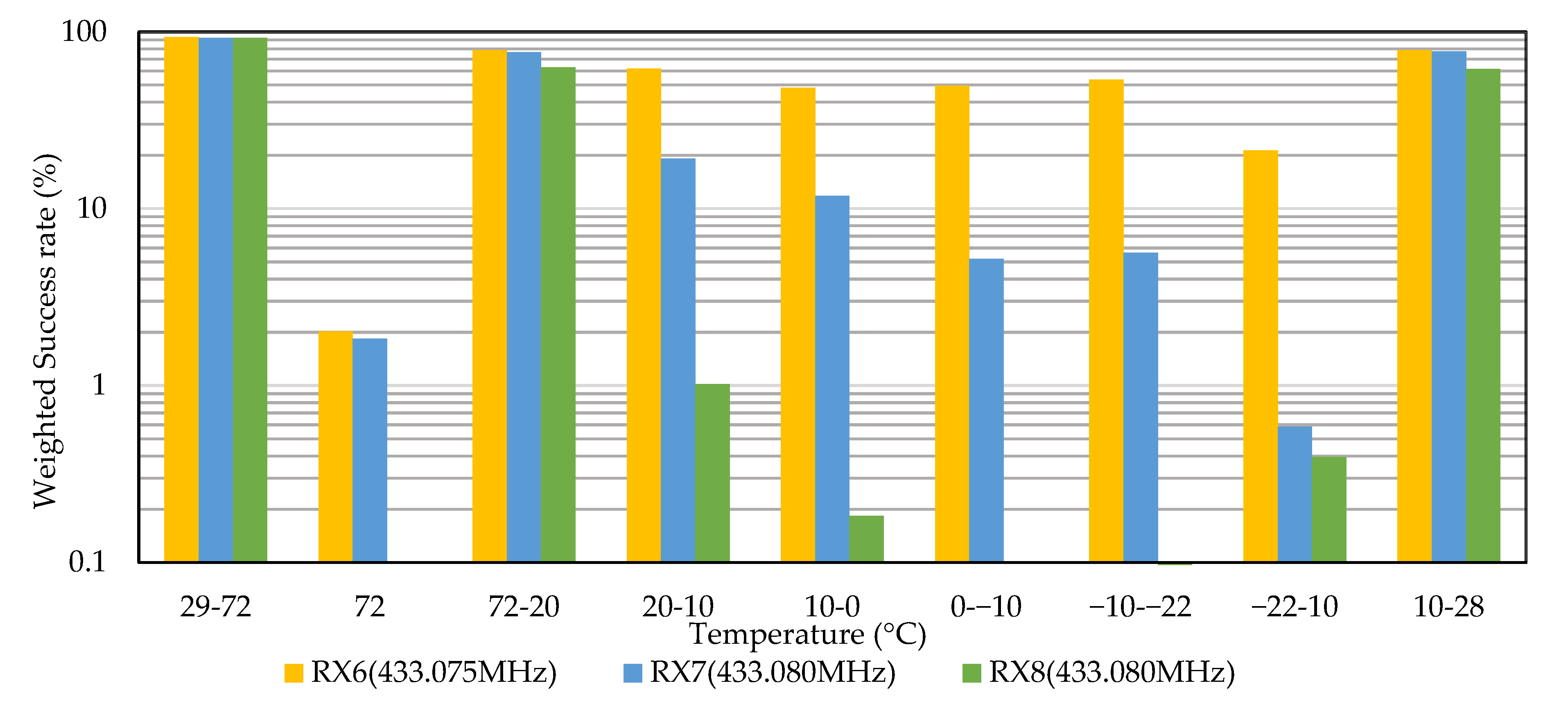
A test with SIoT receiver board and backplane was conducted in Peltier-based Thermal Testing (PeTT) Chamber located at Kyutech. The chamber pressure was maintained below 1 × 10⁻³ Pa throughout the test and the temperature was varied between −22 °C to +72 °C. The center frequencies of the eight receivers were set 5 kHz apart from 433.060 MHz to 433.085 MHz, and data from the GST were transmitted at 433.080 MHz.
The reception of the data was evaluated on the weighted success that is a measure of number of packets received for transmitted packets and the success rate of the bytes in the data. The test results are summarized in
Figure 17 for the three receivers; RX7 is the tuned frequency, RX6 is receiver with 5 kHz lower CF and, RX8 with 5 kHz higher CF.
It was observed that the receiver performance was not affected by increase in temperature up to 72 °C; however, only 3 packets out of 105 packets were received by RX6 and RX7 with a byte success rate of 64% at 72 °C. The performance of the receivers deteriorated when the temperature was reduced below 20 °C, an apparent change in the center frequency was noted since the receiver RX6 received more packets with correct bytes than RX7 and RX8. At cold temperatures, the center frequency of the receiver increased. The performance of the RX-7 further reduced at lower temperatures while RX6 continued to receive packets with 50%-byte success rate. At the minimum of −22 °C, the success rate was low for all the receivers, nevertheless RX6 continued to perform better than the other two. The temperature was increased to set the receivers to ambient temperature and just over 10 °C, and all receivers received the correct data packets.
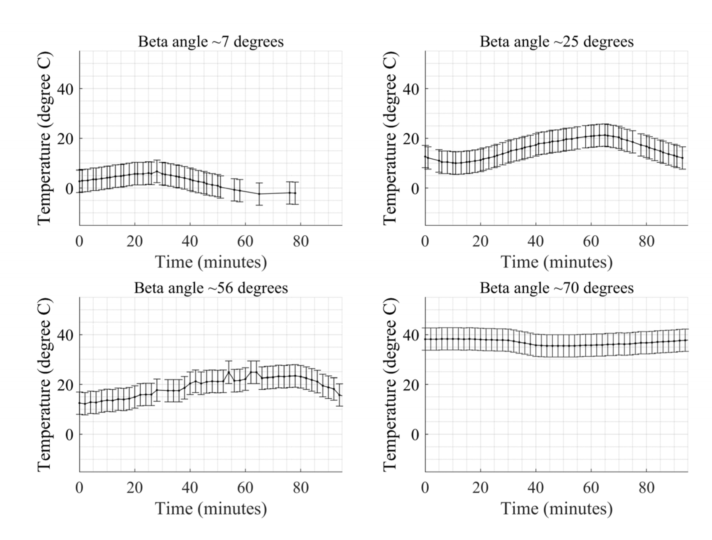
This temperature dependence could be correlated to the temperature profile in-orbit for deriving the efficiency factor for temperature. The on-orbit temperature of the backplane, which is similar to the temperature of the SIoT board, was below 10 °C when the beta angle was below 25 degrees and increased up to +42 °C at maximum beta angle.
Figure 18 shows the temperature of SIoT board obtained from on-orbit housekeeping data with error bars for varying beta angles.
The efficiency factor for temperature can hence be derived from the performance of the receivers with a threshold of 10 °C, which is true when the beta angle is above or below 25 degrees, as shown in Equation (7).
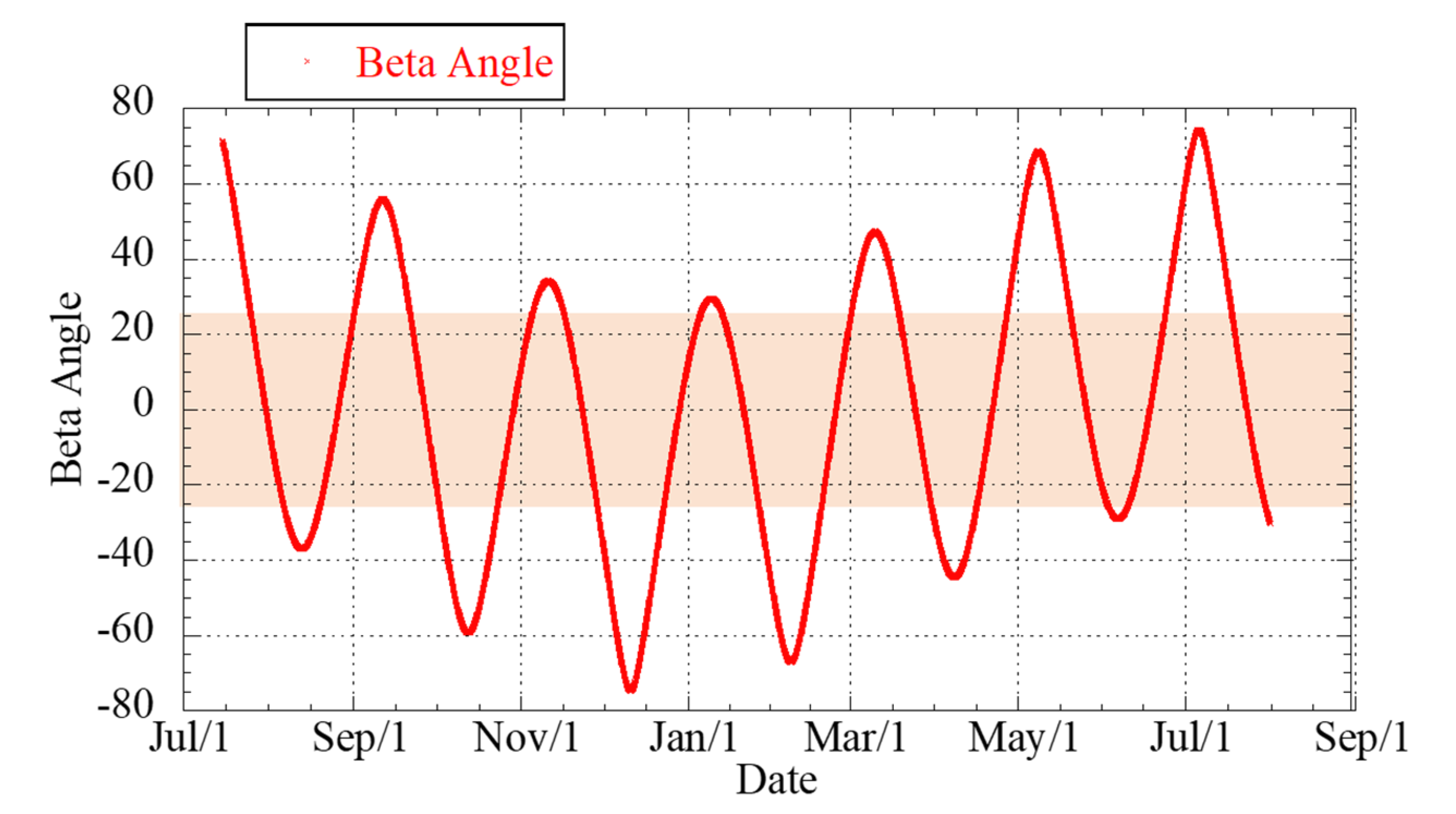
The absolute beta angles in the LEO orbit of 400 km vary between 0–74 degrees, and the beta angle simulation is performed in STK software for the period of one year, as shown in
Figure 19. The beta angle is above 25 degrees for 59% of the total simulated duration. Using Equation (7) for the total amount of data that can be collected inclusive of temperature impact, about 70% from the total estimated data for one year could be retrieved.
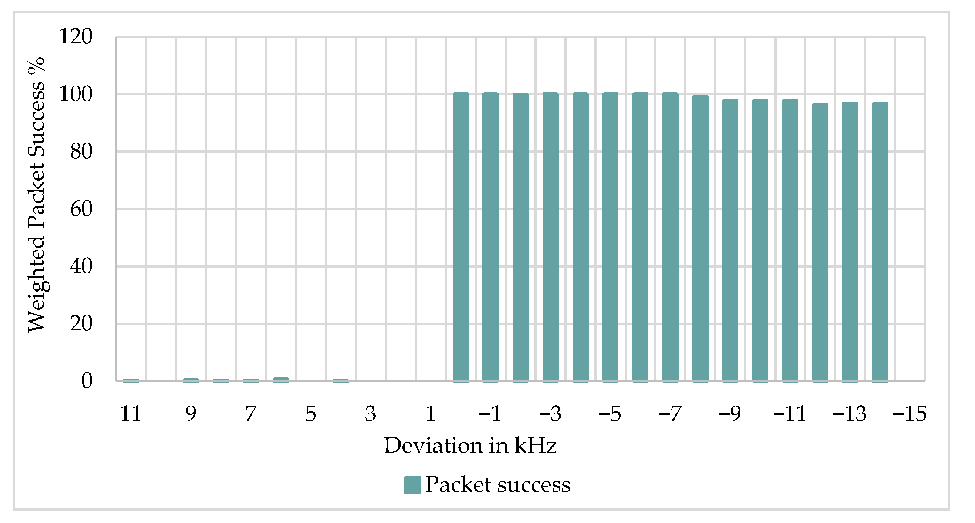
3.5.2. Efficiency Factor due to Doppler Effect Mitigation (ηD)
In LEO satellite at 400 km, the Doppler effect can cause a frequency offset of up to ±10 kHz to the data signal arriving at the receiver. Many studies on the ground for LoRa modulation immunity to the Doppler effect were performed. To confirm the immunity of the designed receivers against the static Doppler effect, the designed receivers were configured to have center frequency deviation in steps of 1 kHz up to ±15 kHz and 100 data packets were transmitted at each deviation. The success rate was calculated based on the number of packets received and the correctness of the bytes. The tests confirmed that the receivers could receive data packets with 95% accuracy up to −14 kHz deviation, but positive deviations were not tolerated. The summary of the results is depicted in
Figure 20. This means the receivers have a higher probability of receiving the packets if they were transmitted at higher frequencies than the tuned center frequency. This shall be verified on-orbit further.
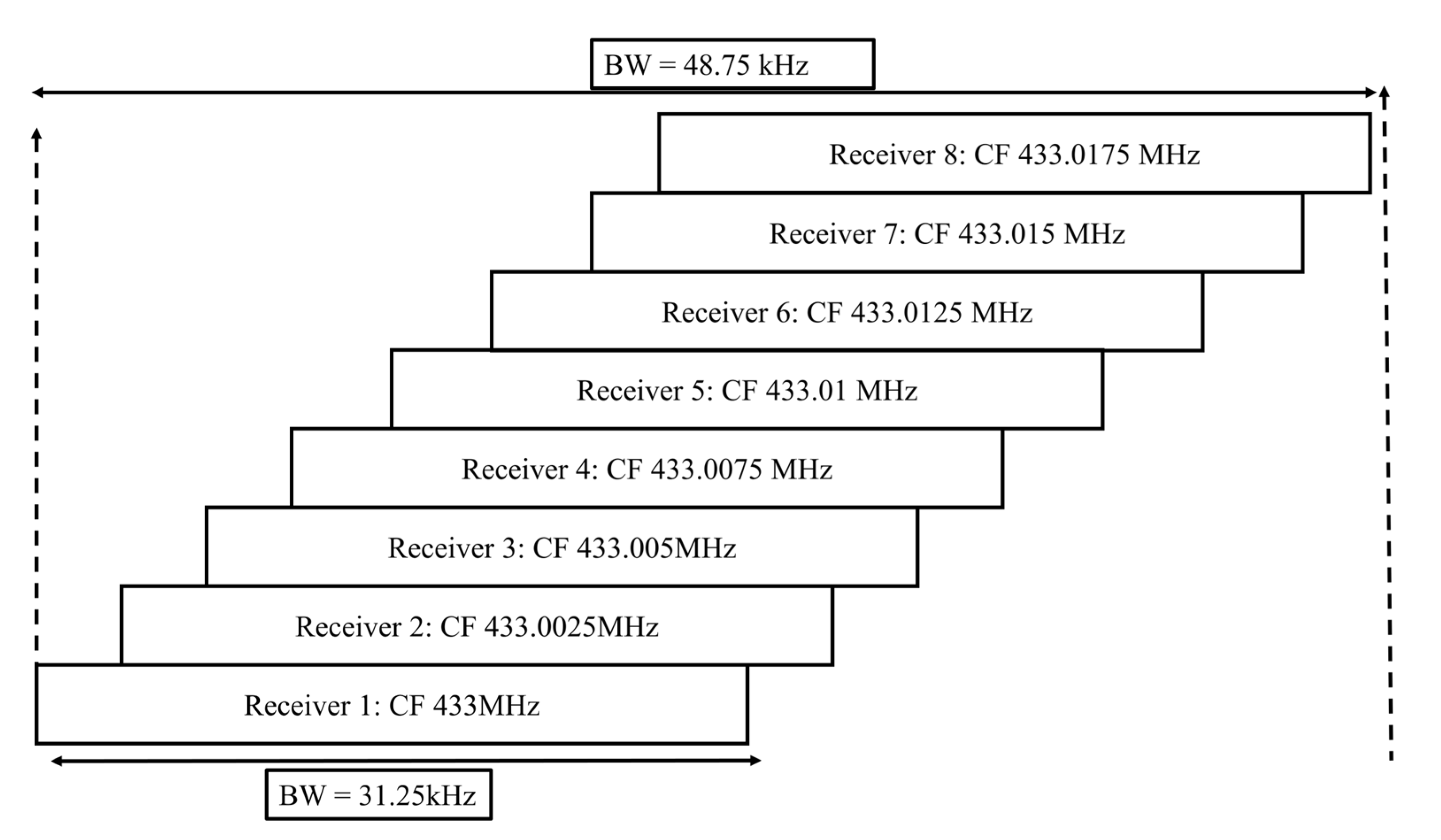
Since there are eight receivers in the SIoT board, the change in center frequency due to the Doppler effect can be accommodated by overlapping the center frequencies of the receiver so that other receivers tuned at slightly higher or lower frequencies can still receive the data packets. The configuration of eight receivers for passive Doppler shift mitigation is shown in
Figure 21, with the channel of each receiver overlapping each another. This makes the system mitigate the impact of center frequency offsets due to the Doppler effect.
The overlap of center frequencies is subjected to reduction in the overall system efficiency by at least 25% considering the receivers in the extreme ends may not receive the data packets correctly. The efficiency factor due to Doppler-effect mitigation is defined in Equation (8).
The efficiency factor can hence be calculated using Equation (6) using the efficiencies obtained for temperature and Doppler-impact mitigation as follows:
4. Results and Discussion
For estimating the coverage and capacity of a satellite in the ISS orbit to provide services to 11 mostly developing countries, Equation (1) was used, the parameters for which were derived in
Section 3. In summary, the parameters that were obtained for the estimate are detailed in
Table 7.
The parameters are based on the ground test results, simulations and on-orbit results for the designed SIoT payload board and the GST design. The parameters include the antenna radiation pattern for both the satellite monopole antenna and the GST antenna, the sensitivity tests that were performed for the integrated satellite inclusive of all the EMI noises generated by the satellite subsystems, and the link budget calculation inclusive of the losses.
The capacity of the system per day is summarized in
Table 8 for scenarios considering the average of all satellite elevations simulated for a month and the duration of satellite to GST communication during this period. For the maximum capacity estimation, the simulation yielded a total of 22 satellite passes in a day with average elevation of 56 degrees and for minimum, a total of 12 passes with average elevation of 55 degrees were derived. The minimum amount of data per GST that can be received by the satellite per day is 45.50 kB.
Although the estimation is based on the known system inference, it is still optimistic speculating other factors that could affect the performance of the receiver, such as impact of temperature on the receiver capability and the Doppler effect. Therefore, the efficiency factor is introduced in the equation that incorporates the efficiency due to temperature impact and the Doppler-effect mitigation method. Since the temperature on orbit depends on the beta angle of the satellite that varies between 0–74 degrees absolute values, the simulated beta angles with a threshold of 25 degrees for a period of one year are used to estimate the average capacity of the SIoT mission for a year in
Table 9.
The measured environmental parameters in most participating GST Network countries include temperature, humidity, and pressure. Considering at least two decimal digit resolutions for each sensor and assigning 4 bytes for each sensor, 31.79 kB of data in a day and 1.99 kB of data per pass, which is approximately 169 samples, can be collected from each country per day. This data capacity can be divided between multiple GSTs on the ground. In typical applications, the parameters for LoRa modulation such as the SF, CR and bandwidth can affect the amount of data that can be collected from the sensor terminals. Since the receivers are set to receive only five packets of data per minute, reconfiguration of these parameters allows for improving the quality of data packets that shall be received and not increase the upper limit of the capacity.
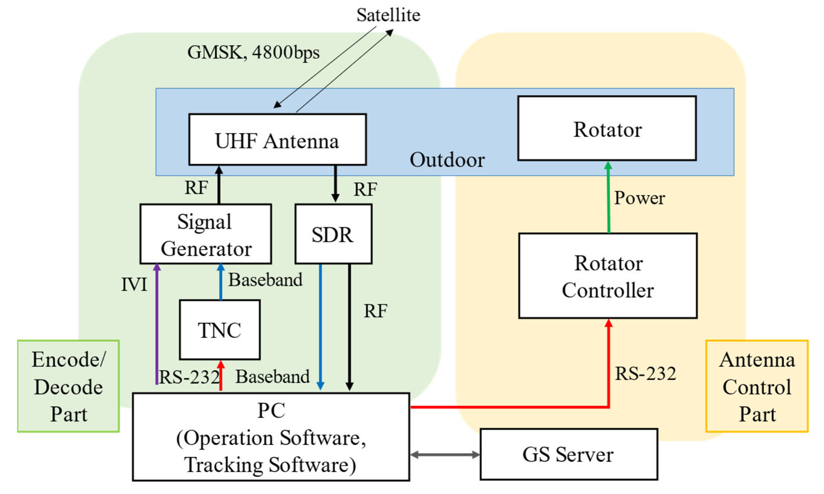
The received data packets are downlinked at Kyutech ground station, the configuration of which is shown in
Figure 22. From the operation experience of previous satellites from the same ground station, approximately 7.9 kB of data can be downlinked per ground pass using 400 MHz UHF frequency. Integrating the data downlinked for four passes a day, all the data collected by the payload receiver can be downlinked and uploaded to the database within a day. The maximum latency between data transmission from the GST to the data reception from the database is 24 h. This latency is acceptable for delay-tolerant applications.
The estimation for the capacity of the mission is made as realistic as possible, inclusive of known parameters for the designed system. The unknown parameters are the on-orbit dynamics, which may change the performance and the capacity of the receivers. The capacity shall be re-evaluated once the mission is made fully functional on-orbit.
In addition to the technical edge of the designed system for the SIoT mission, the involvement of developing countries for the GST network provided a platform to experience ‘hands-on’ while building their own GSTs. Each of these participating countries customized the GST design based on material substitutes available locally, optimizing the design for that country. The overall development cost was targeted to be achieved under
$150 based on a market survey of components in Japan to achieve low-cost requirements [
39] but the actual development cost in the GST countries ranged from
$200 to
$300 due to variation in market prices. The GST community from each country comprises individuals actively involved in developing the space sector, including students from universities, officials in space agencies, and space enthusiasts, who would like to improve space technologies in their country. Most of these countries are participating in demonstrating a proof of concept so that these technologies could be applied in their future projects to solve local issues.
Since there are no publications in the literature that discuss the capacity of a SIoT based on the actual design of a CubeSat and the limitations due to the design, the proposed system cannot be compared quantitively for the performance evaluation. Instead, this study could serve as a base for quantitative comparison for satellites that will be developed in the future for S&F remote data-collection missions. There are areas of improvement that are currently being implemented in the Micro Orbiter-1 (MO-1) mission, which is a 1-unit CubeSat being developed at Kyutech. MO-1 will have two S&F payloads, which will have eight receivers each onboard, for the frequencies of 400 MHz and 920 MHz, and the 400 MHz board is a replica of the KITSUNE payload board; however, the 920 MHz is an improvised version of the 400 MHz board with 70 mA lesser power consumption. Communication tests are underway, and the preliminary test results showed similar receiver sensitivity to the KITSUNE S&F receiver. As a result, it is under study to improve the receiver sensitivity further.


 ,
, 


