1. Introduction
Recently, in the context of the demand for low-cost and rapid manufacturing, metal-based mirrors have been widely used in aerospace payloads for commercial and military purposes [
1,
2,
3,
4,
5,
6]. Metal mirrors, especially aluminum alloy mirrors, can realize passive athermalization, and are proven to have good stability [
7]. They are ideal materials for developing high-cost performance optical systems [
8].
In order to achieve an ultra-compact layout and small moment of inertia, the most effective method is to increase the curvature (or steepness) of the mirror. This means that an ultra-lightweight design becomes more difficult to achieve, especially for the specific stiffness (
). It is still a technical challenge to realize a high steepness and ultra-lightweight design with low-specific-stiffness aluminum alloy materials [
9].
The bending stiffness of the mirror is positively correlated with the thickness of the mirror. The suitable selection of an initial mirror thickness can improve the iterative efficiency of a lightweight design with high steepness.
Many scholars have conducted outstanding research on the construction of initial mirror models. One method is based on an analytical deformation solution of a thin elastic plate with a circular thickness distribution under easily supported boundary constraints [
10,
11]. The other method is to establish a parametric topology shape optimization model, using an optimization algorithm to determine an optimal solution in the global solution [
12,
13]. Both methods require a lot of calculation and data processing, and it is impossible to quickly plan the initial mirror thickness suitable for an accurate mirror surface, which means that it is difficult to achieve fast modeling and performance estimation.
The thin plate hypothesis theory can be used for estimating the self-deformation of a mirror with a small curvature aperture under the condition that the mirror diameter thickness ratio (diameter/thickness) is fixed [
14,
15,
16]. For mirrors with large curvatures, especially elliptic mirrors, it is impossible to directly use the thin plate theory to select the appropriate mirror diameter thickness ratio. Further research is needed in order to quickly select the mirror diameter thickness ratio using an analytical approach.
Topology optimization is an effective way to achieve a very lightweight design. Topology optimization and additive manufacturing are combined to reduce the weight of the mirror by about 20% under the same mechanical properties, which has been applied in designing small-aperture metal mirrors [
17,
18]. However, for medium- and large-aperture metal mirrors, the traditional material reduction manufacturing method remains the main design choice at this stage [
19]. In order to simultaneously meet the high-steepness and very lightweight design of aluminum alloy mirrors, the lightweight structure of the back of the mirror should be optimized after the thickness ratio of the mirror is selected.
This paper introduces a new method for the equivalent design of a high-steepness aluminum alloy mirror. Firstly, a high-steepness elliptic mirror plate equivalent method was proposed to quickly select the mirror diameter thickness ratio, as described in
Section 3. Through the combination of topology shape optimization and theoretical calculation, a very lightweight mirror structure suitable for single-point diamond turning (SPDT) was established, as detailed in
Section 4. Then, the author describes the completed finite element simulation analysis in
Section 5 and completed static accuracy test and dynamic stiffness test in
Section 6. The test results verify that the high steepness mirrors designed by this method have a high static accuracy and dynamic stiffness.
2. Design Input and Flow Chart of Mirror
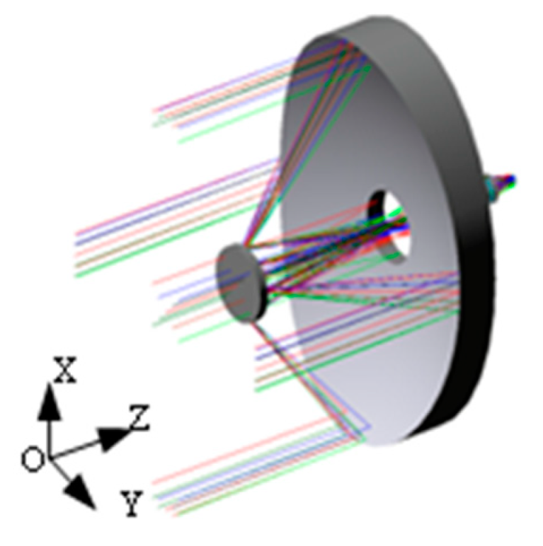
The optical system introduced in this paper is derived from the infrared high-sensitivity remote sensing load of deep space exploration, which is limited by the constraints of the platform, and the envelope volume of the optical load needs to be strictly controlled. The optical system is shown in
Figure 1. In order to reduce the distance between primary and secondary mirrors, the primary mirror of the optical system bears a large focal power.
According to the design requirements of the optical system, the quantitative index requirements of the primary mirror are set, as shown in
Table 1.
The larger the steepness of the mirror, the more difficult it is to design and manufacture. For a mirror of such high steepness, it is necessary to study a design method that can quickly complete the initial structure evaluation and verification.
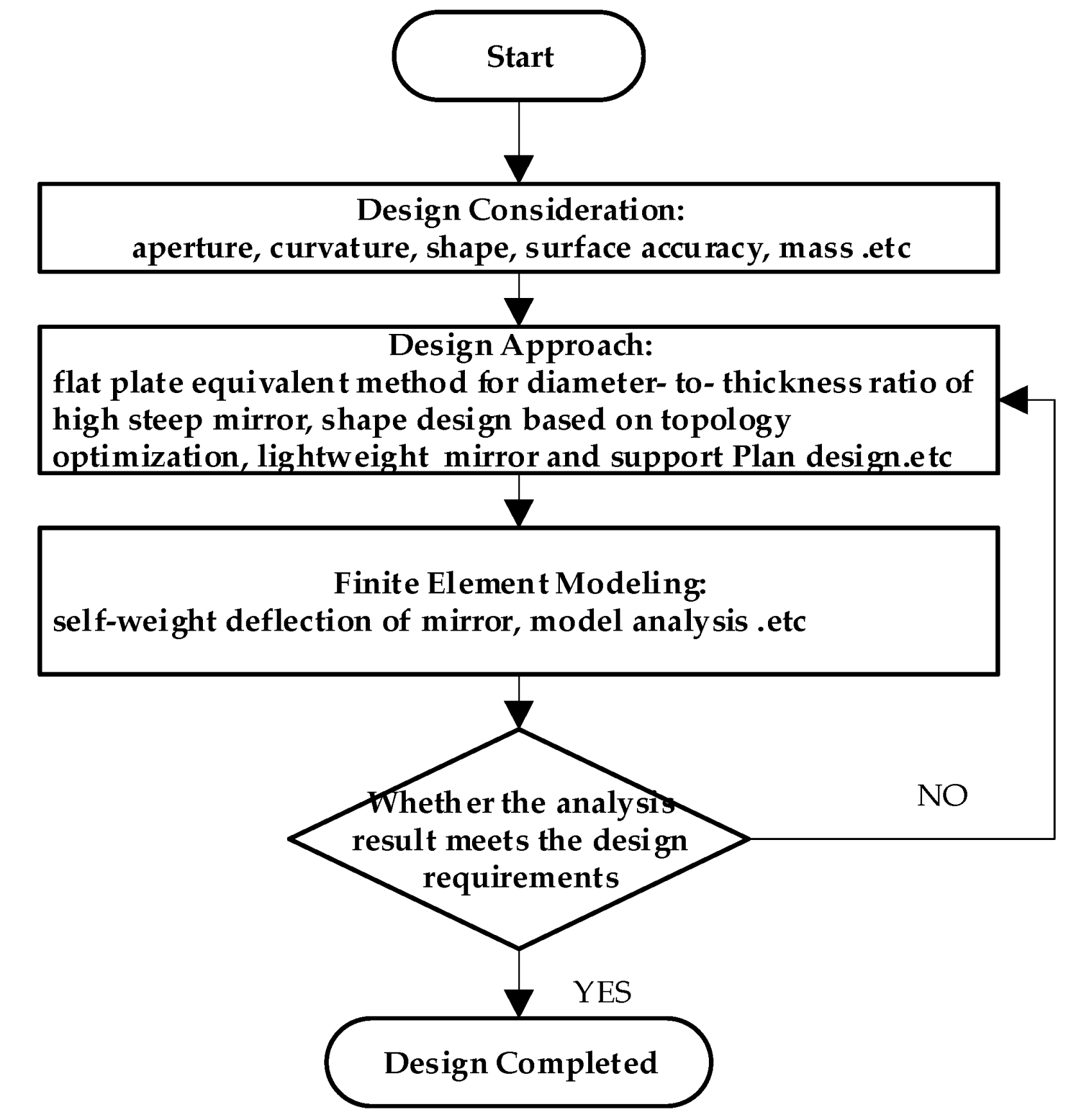
Figure 2 provides a flow chart for the design of a high-steepness lightweight elliptical mirror. Firstly, an equivalent method to design an elliptical mirror plate with high steepness is proposed to quickly select the mirror diameter thickness ratio. By combining topology shape optimization and theoretical calculations, a mirror structure suitable for SPDT turning was established. Then, the rationality of the design was verified by a finite element simulation analysis.
3. Equivalent Design Theory of a High-Steepness Mirror
3.1. Plate Equivalence Theory and Self-Weight Deflection
For a cylindrical or rotationally symmetric mirror, if the change in the mirror section is less than about 10% [
20], the axial self-weight deflection can be calculated by the following equation:
where
δ is the maximum self-weight deformation of the mirror,
ρ is the unit of material density,
R is the mirror half-aperture,
E is the unit of the elastic modulus of material,
t is the mirror thickness, Δ is the diameter thickness ratio,
g is the acceleration of gravity,
v is the poison ratio of the material, and
D is the mirror aperture.
Equation (1) can be used to estimate the initial diameter thickness ratio of the mirror. It is relatively easy to predict the self-weight deflection of the mirror with a given aperture under different equivalent bending thicknesses based on the flat plate theory.
3.2. Flat Plate Equivalent Method for High Steepness Circular Mirror
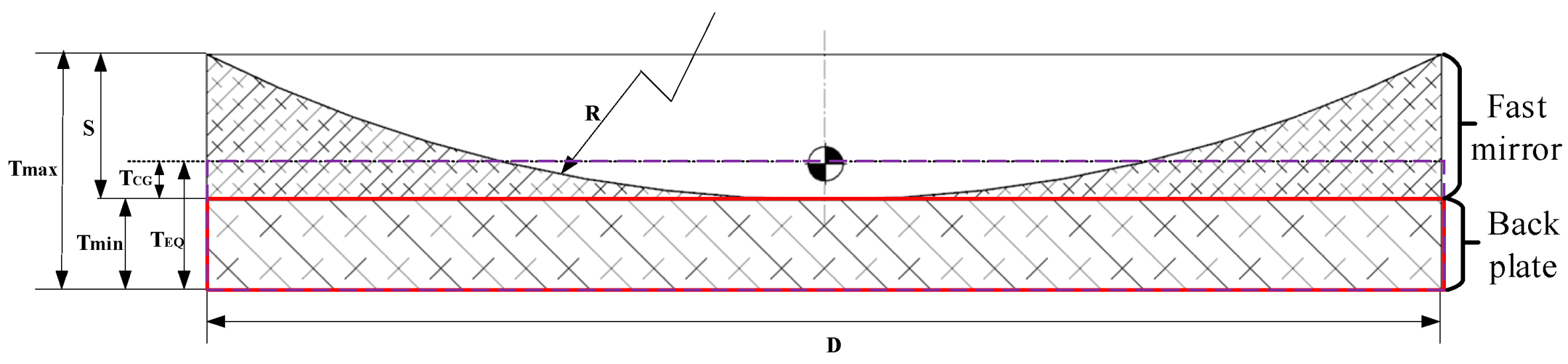
The primary mirror of modern large telescope optical system is made with a relatively fast primary focal ratio and high steepness, whose center thickness Tmin and edge thickness Tmax greatly differ. Since the radius of the curvature of a mirror with a fast focal ratio is relatively short, the sagittal depth is quite large.
The combination of a fast focal ratio and thin mirror leads to a large change in the thickness of the mirror from the center to the edge. Whether Tmin or Tmax is selected for the equivalent plate thickness, the self-weight deflection obtained in the analysis has a large error, which is not conducive to the rapid convergence of the initial structure of the mirror. Therefore, it is vitally important to establish a plate equivalent model with a smaller initial error to facilitate rapid modeling and performance estimation.
For high-steepness flat–concave mirrors, the mirrors can be divided into two parts, the mirror body and the back plate, as shown in
Figure 3. The back plate is used as the basic thickness
Tmin of the equivalent plate, the equivalent thickness of the mirror part is
Tmirror, and the final equivalent thickness of the plate is
TEQ:
We focus on the equivalent thickness of the mirror body. Since the center of mirror weight of high steepness mirror changes with the changes in mirror curvature and aperture, we propose that the distance between the center of gravity of the mirror body
TCG and the back plate is taken as the equivalent plate thickness
Tmirror of the mirror body. The following relationships are satisfied:
For the sake of simplicity and generality, the best-fitting sphere can be used to replace the aspheric surface for the initial structure modeling of the aspheric surface with a small deviation, thus reducing the complexity of modeling. The parsing expression is as follows:
where
R is the best fitting spherical curvature radius of the high-steepness mirror,
D is the diameter of the mirror, and
S is the sagittal depth difference between the outer edge of the mirror and the center of the mirror.
3.3. Flat Plate Equivalent Method for High-Steepness Elliptic Mirror
In this paper, we mainly focus on a high-steepness elliptic mirror. Since the shape and curvature of the mirror is not regular, we propose a method of “volume” equivalent to convert a high-steepness elliptic mirror into equivalent radial steepness circular mirror. Then, using the method described in
Section 3.2, the circular mirror is converted into an equivalent axial parallel plate. In this way, the choice of an initial mirror diameter–thickness ratio can be quickly realized through the self-weight deflection formula of the parallel plate.
3.3.1. Radial Equivalent
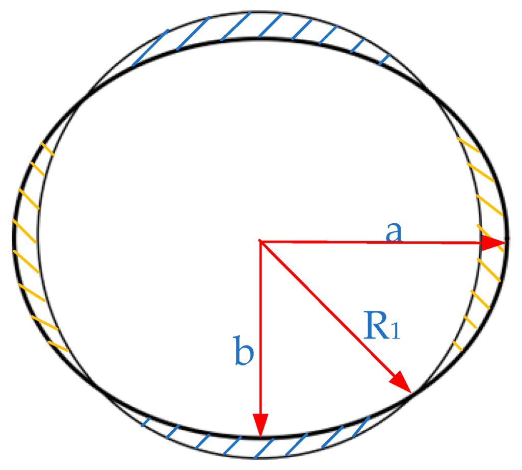
Radial equivalence is to transform the elliptic section into a circular section, which is approximated by “equal area” method,
. The equivalent analytical expression is shown as follows:
where
S is the area of the equivalent circle,
a is the size of the long half-axis of the oval mirror,
b is the size of the short half-axis of the oval mirror, and
R1 is the radius of the equivalent circle.
The schematic diagram of radial equivalence is shown in
Figure 4.
3.3.2. The Axial Equivalent
The axial equivalent method is to calculate the mirror diameter–thickness ratio of the equivalent circular mirror by using the method described in
Section 3.1 above. In this case,
D = 2
R1, and
Tmin of the back plate thickness of the initial oval mirror can be estimated according to the equivalent circular plate.
3.4. Area–Mass Density
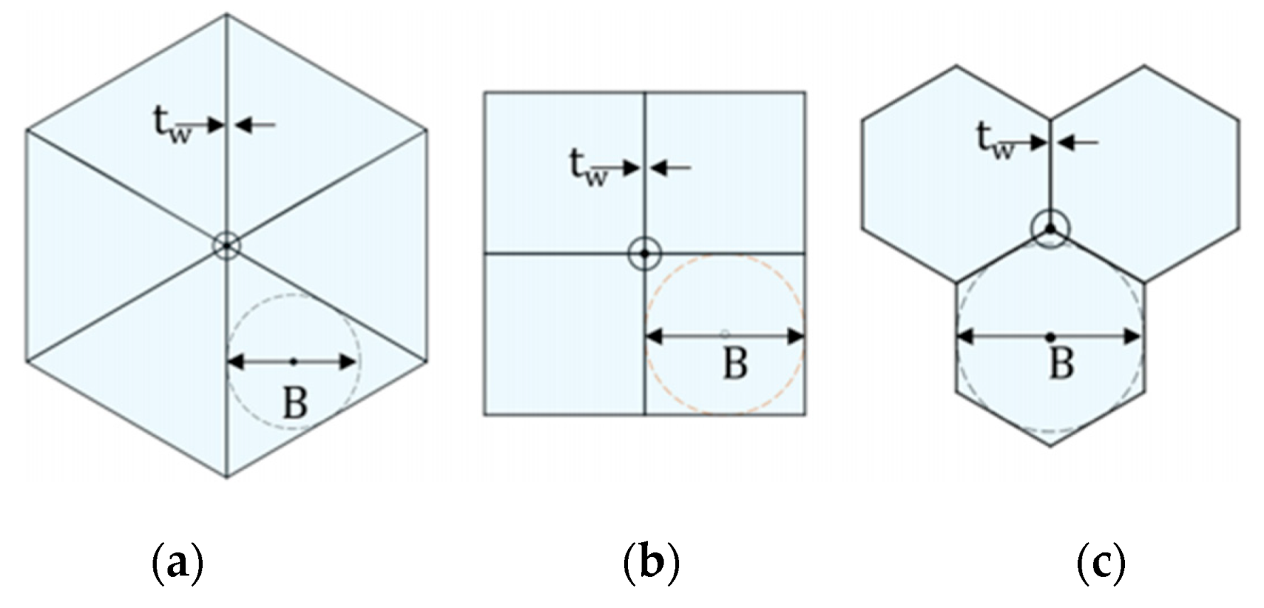
In order to evaluate the quality characteristics of lightweight mirrors, the area–mass density is introduced. Therefore, lightweight mirrors are measured in terms of area–mass density or mass per unit area [
21]. The general form for estimating the mass per unit area of the mirror is shown in Equation (7):
In the formula, m/A is the area–mass density, ρ is the material density, tf is the mirror face–sheet thicknesses, η is the solidness ratio, and hc is the isogrid cell depth.
The solidness ratio can be calculated using Equation (8) as follows:
where
B is inscribed circle diameter, and
tW is shear core rib thickness.
For commonly used lightweight structures, the expressed parameters are shown in
Figure 5:
4. Optomechanical Design and Optimization of Mirror
4.1. Initial Structure Selection
According to the equivalent method in
Section 3, the thickness of the mirror can be selected to meet the bending stiffness requirements. In order to realize the high lightweight design of the mirror, it is necessary to select the support structure and optimize the lightweight structure.
Commonly used mirror support methods include center support, back support, peripheral support, etc. For high-steepness and very lightweight mirrors, the use of peripheral support will cause gravity deformation and collapse along the optical axis. Center support and back support are two commonly used support modes for small- and medium-sized mirrors. In order to combine the advantages of the rapid manufacturing and assembly of metal mirrors, the center supporting structure, which is easy to design, is selected as the preferred support scheme of the mirrors.
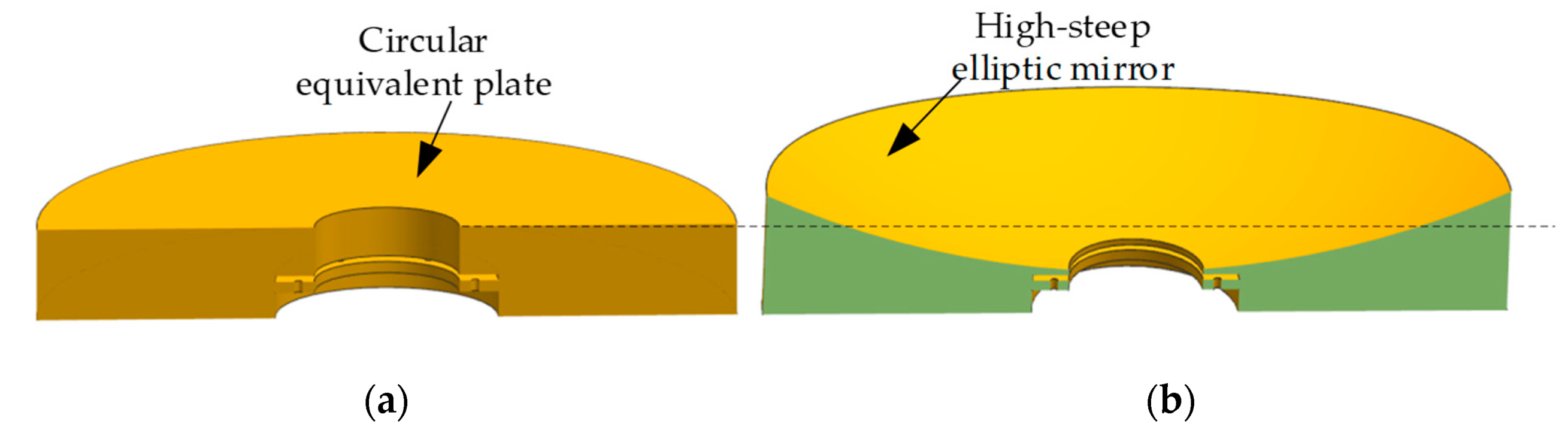
In order to reduce the mounting stress caused by the support structure connecting to the mirror, the mounting flange is generally isolated from the mirror, as shown in
Figure 6. The diameter of the mirror is 410 mm × 310 mm. According to the above equivalent method, the elliptic mirror is equivalent to a circular plate. Formula (5) is used to calculate the mirror diameter–thickness ratio using the circular plate, and
δ is 0.032 μm (1/20 λ, λ= 632.8 nm). According to Formula (1), the equivalent diameter–thickness ratio
δ = 8.77, the equivalent mirror thickness = 41.25 mm, and
Tmin = 28.9 mm. The weight of the solid model of the elliptic mirror designed by UG software is 12.5 kg, and the weight of the equivalent circular mirror is 12.6 kg, which approximately equates to the equivalent of “equal volume”.
4.2. Mirror Shape Optimization
In the previous section, we described the completed construction of the initial structure of the solid mirror, which was unable to meet lightweight design requirements.
In order to reduce the weight of the mirror, large-aperture mirrors are usually designed to be single-arch, double-arch, flat back and other special shapes. Therefore, it is necessary to select a reasonable lightweight structure based on the processing characteristics of the mirror.
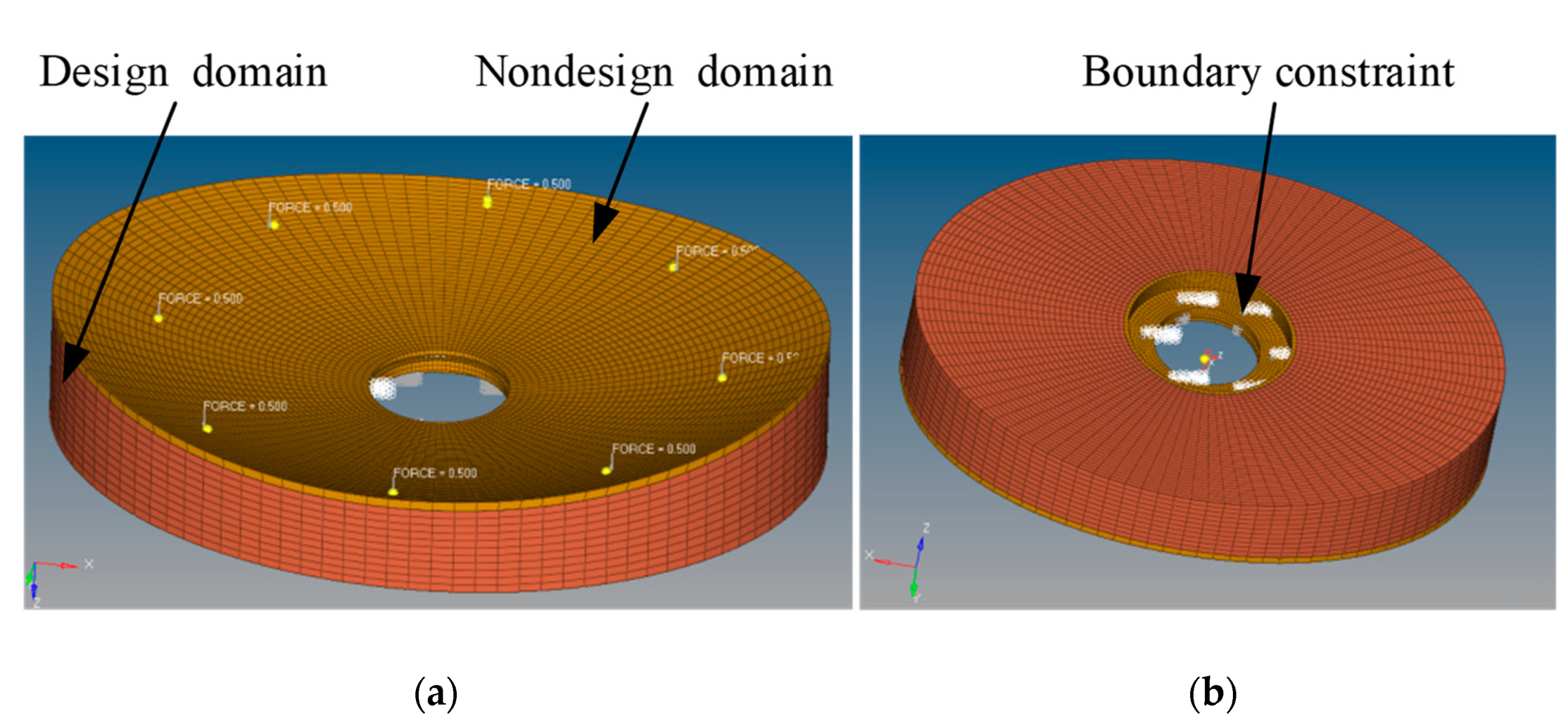
We chose a topology optimization design combined with the characteristics of mirror processing to complete the shape optimization of the mirror, allowing us to carry out conceptual design. Topology optimization is a mathematical method to optimize material distribution under given load conditions, boundary conditions and performance constraints [
22,
23,
24], as shown in
Figure 7.
Based on the constraints of the single-point diamond turning process, the design requirements of turning force on the lightweight support stiffness of the mirror back were analyzed. Machining turning force is a static optimization problem, which usually takes the minimization of structural compliance (or the minimization of strain energy and the maximization of stiffness) as the objective function and the structural volume ratio as the constraint function. Its mathematical model can be expressed in Equation (9):
where
C is the compliance of the mirror,
is the unit density variable,
K is the global stiffness matrix,
U is the global displacement vector,
is global load vector is the design domain volume constraints,
is volume fraction, and
is design domain volume.
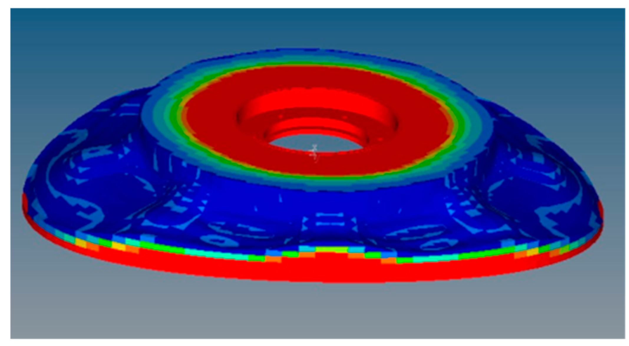
Topology optimization design can provide a good reference to guide the design of a lightweight structure for the mirror back according to the density distribution. We use the optimization module of HyperMesh software (Altair, Troy, MI, USA) to complete the topology optimization analysis under given boundary constraints. After 25 iterations, the optimization results converge to a stable value. The density ranges from 0 to 1. The closer the density is to 1, the more important the structure is, which can be retained according to the actual design. The closer the density is to 0, the less important this part is [
25]. This can be appropriately removed according to the actual design. In order to ensure the continuity of materials, we choose the result of threshold 0.1 as the reference result of shape optimization. As shown in
Figure 8, it can be seen from the iteration results that a better lightweight density distribution of the mirror design is that less material is left in the long axis and more material is left in the short axis. The back shape of the mirror is a single arch. Unfortunately, the existing topology optimization results still failed to meet our expected requirements, but provided a direction for the subsequent lightweight design.
4.3. Parameter Design of Mirror
As additive manufacturing is a good lightweight design method, we can choose many typical lattice structures to complete the filling of mirror hollow structure, to achieve a high stiffness and very lightweight design [
26]. Unfortunately, limited by the project cycle, we chose the conventional aluminum alloy 6061-T6 as the mirror material for this phase, and the lightweight structure needs to be completed by conventional milling. Therefore, the mirror-back lightweight structure is selected from three commonly used lightweight structures (triangle, square and hexagon). Triangular and hexagonal lightweight structures have similar effects on weight and shape accuracy. However, the use of triangular lightweight structure can improve the natural frequency by 10%, so we chose a triangular lightweight structure as the mirror’s lightweight scheme [
27,
28].
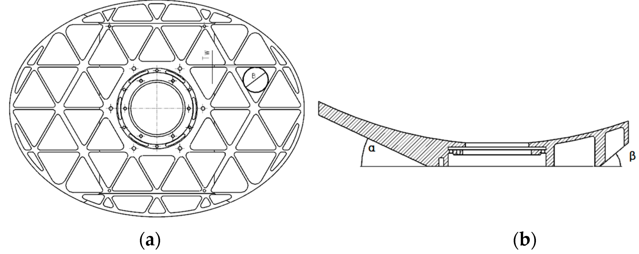
In combination with Formula (1), factors such as the mirror diameter thickness ratio and material properties are considered. We chose the diameter of the tangent circle of the triangle B = 35.6 mm, the lightweight rib TW = 3 mm, the edge thickness Te = 5 mm, and the solidness ratio 0.15.
The thickness of the lightweight reinforcement is
T = 7 mm. This reinforcement measure can improve the stiffness of the main load-bearing structure of the mirror. In addition, edge cutting was carried out in the long and short axis directions of the mirror, and more supporting materials were left on the short axis side with topology optimization and shape optimization as references. After edge cutting, the resulting lightweight mirror α = 25.3°, β = 40°, with a weight of 3.4 kg is shown in
Figure 9 below. Compared with the initial structure of solid mirror, the lightweight rate is better than 72%, and the equivalent surface density reaches 34 kg/m
2.
5. Finite Element Analysis
Through calculation and evaluation, we completed the design of the mirror. In this chapter, the finite element model of the mirror component is described, and the static and dynamic simulation analysis is completed to verify the rationality and feasibility of engineering the design scheme.
5.1. Gravity Deformation Analysis
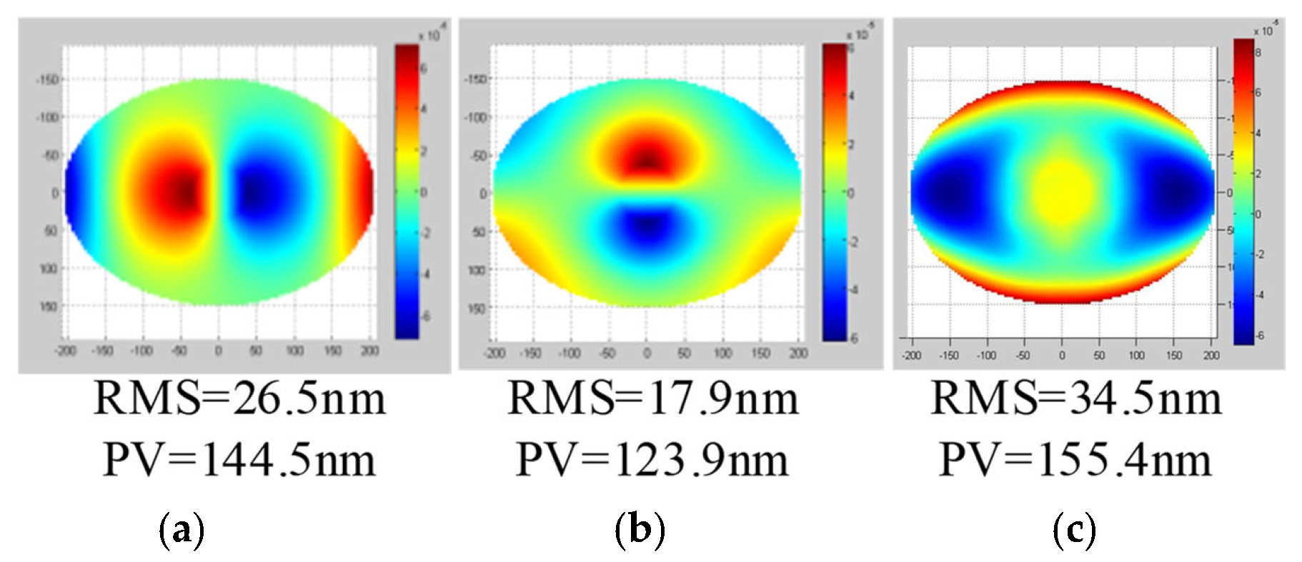
Since the designed application of the mirror described in this paper is in the space environment, the mirror processed in the ground environment will cause the space degradation of the surface shape. In order to predict this degradation, we generally apply a gravitational acceleration of 1 g to the mirror on the ground to evaluate the surface shape change from the mirror into space. The shape of the mirror we studied is elliptical and has no rotational axis of symmetry, so self-weight deflection in three directions needs to be analyzed.
By removing the rigid body displacement and angle, the surface shape fitting is carried out using MATLAB software(MathWorks, Natick, MA, USA). The analysis result of the mirror is better than 35 nm (RMS), as shown in
Figure 10, which meets the performance requirements of the mirror.
The previous equivalent modeling method is constructed in the vertical direction of the optical axis. The reason for this is that the gravity deformation of the medium- and large-aperture mirror in the vertical direction of the optical axis is more difficult to control. Therefore, ensuring the minimum gravity deformation of the mirror in the vertical direction of the optical axis is the main optimization goal of the design. In the finite element analysis of gravity deformation, we focus on the vertical deformation of the optical axis. The design value of the equivalent gravity deformation for the plate with a high steepness is 31.64 nm (1/20 λ, λ = 632.8 nm), and modeling error and finite element analysis error are within 10%, as shown in
Table 2. Gravity analysis results show that the equivalent model has a high precision.
5.2. The Modal Analysis
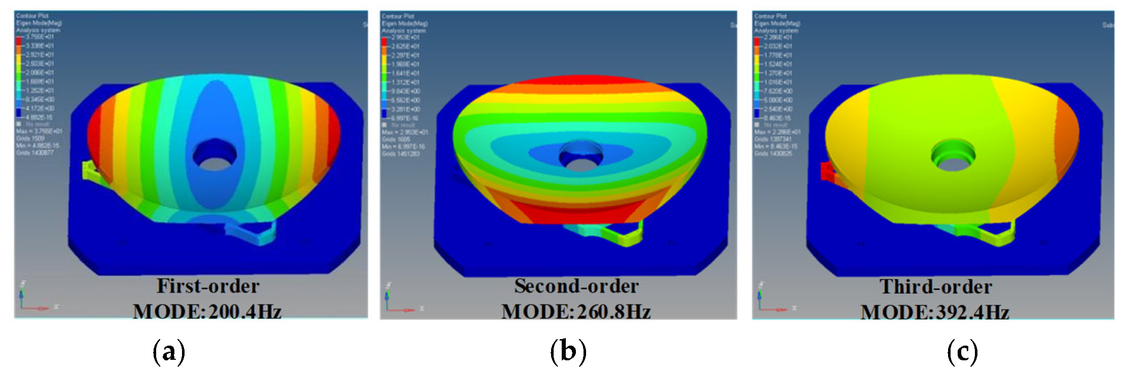
The fundamental frequency of the mirror assembly not only determines its static stability, but also affects its dynamic stability. Further modal analysis is required to verify the sufficient local and overall stiffness of the optimized structure.
Figure 11 shows the first three modes of the mirror assembly, and
Table 3 shows the mode participation factors ratios in each mode.
It can be seen from the analysis results that the first and second modes of the mirror module rotate around the Y−axis and X−axis, respectively, and the third mode is translation along the optical axis. The first mode of the module is 200.4 Hz. The analysis results show that the mirror has sufficient stiffness.
6. Verification and Surface Accuracy Testing
6.1. Test of Surface Shape after SPDT
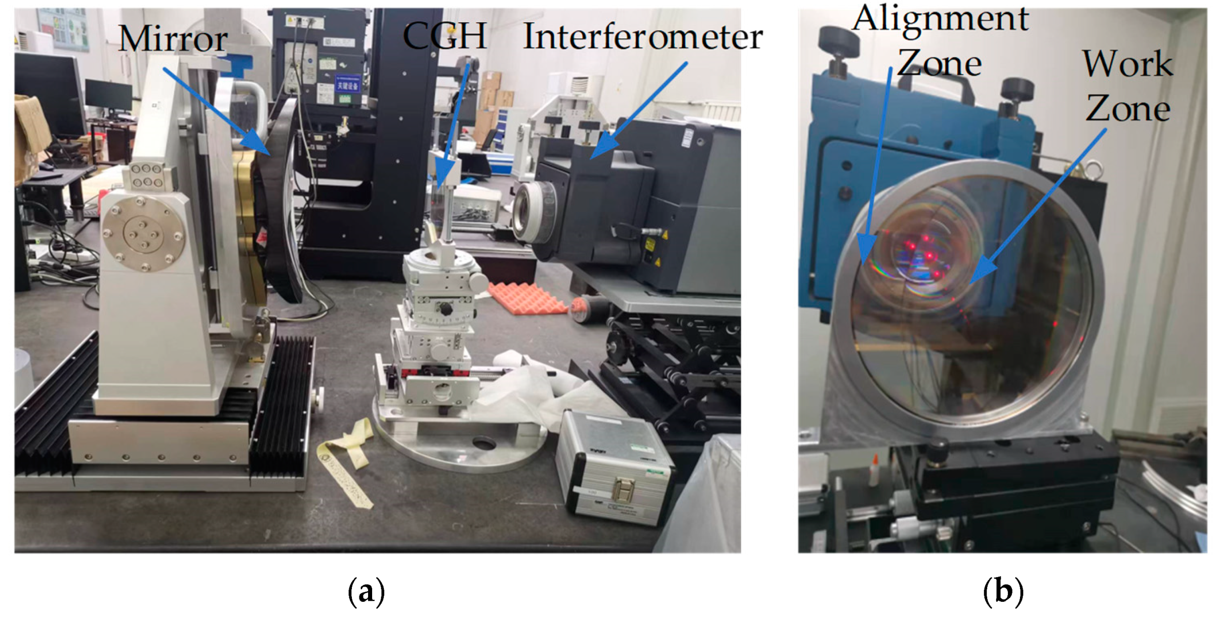
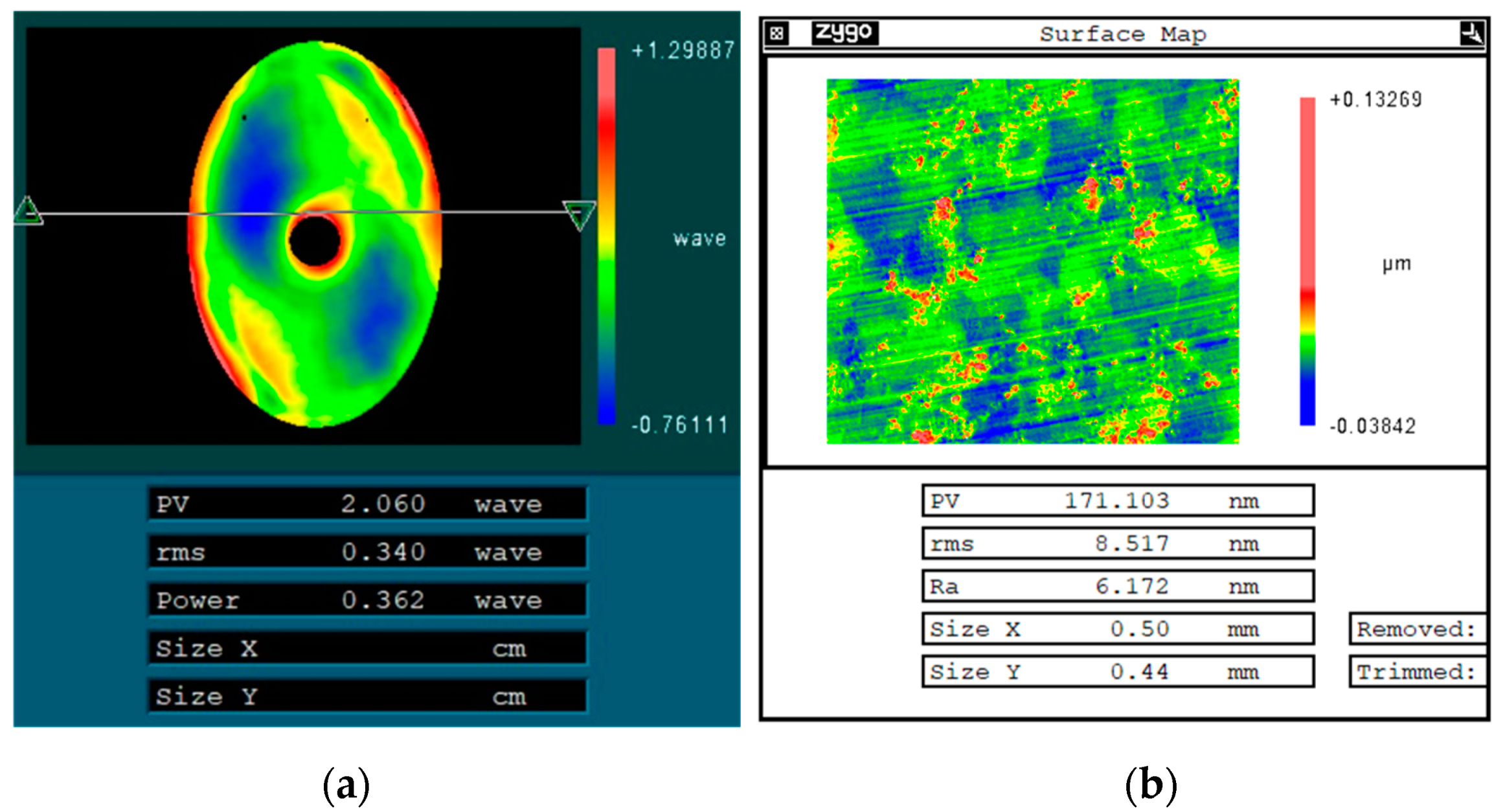
After SPDT manufacturing, the mirror assembly was tested using computer-generated hologram (CGH) components.
Figure 12 shows the test optical path. CGH can produce an oddly shaped wavefront without making expensive references or null optics [
29]. The detection area of the primary mirror is oval, and a circular cat eye area is designed outside the oval detection area to achieve a high precision and fast alignment. The test results show that the low-frequency surface shape error is 0.34 λ (λ = 632.8 nm), and the high-frequency surface roughness error is Ra 6.172 nm after single−point machining, as shown in
Figure 13. Periodic turning tool patterns can also be seen on the surface.
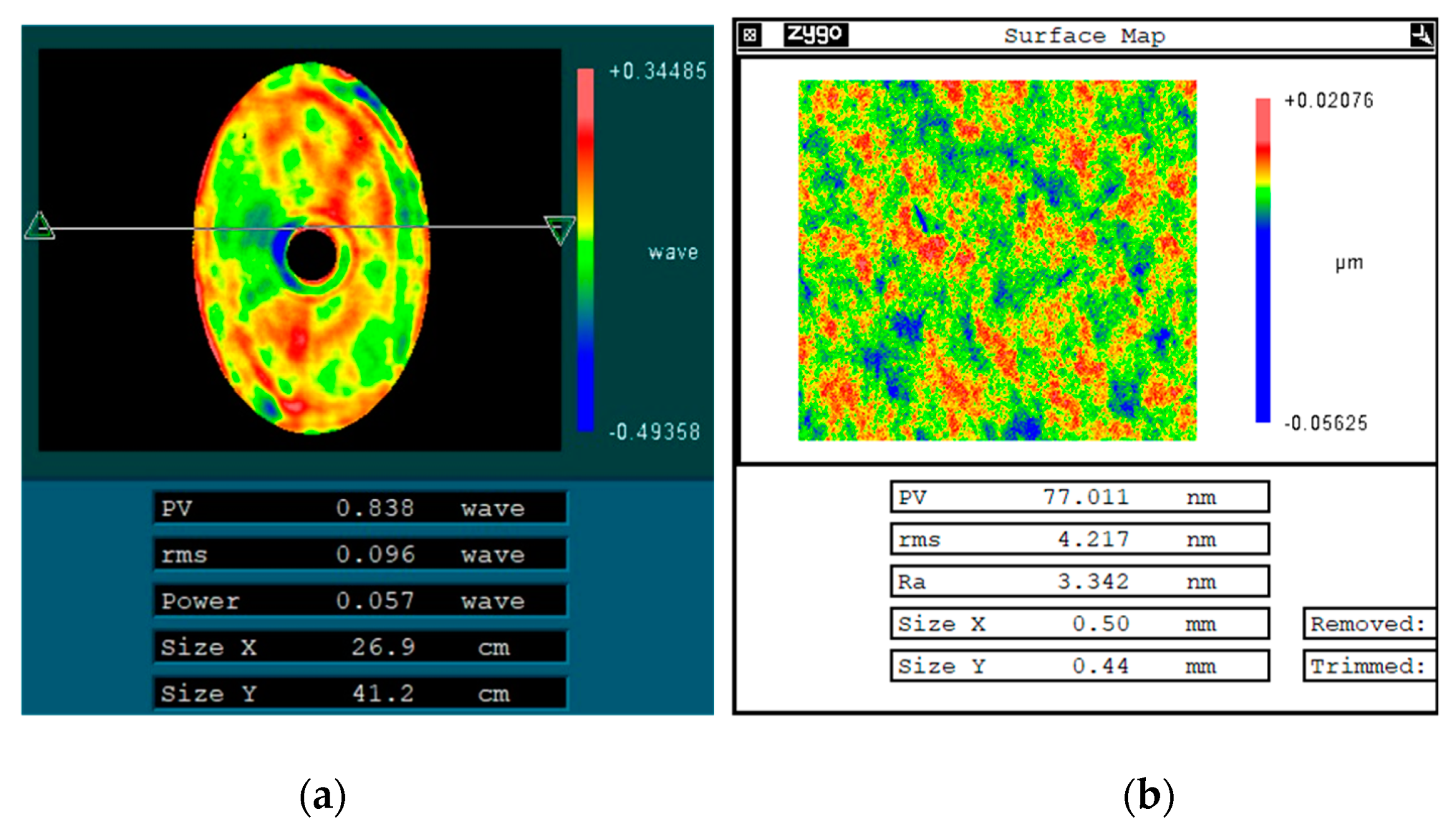
6.2. Mirror Polishing
The low-frequency and high-frequency errors of the mirror were corrected by non-Newtonian fluid polishing combined with chemical mechanical polishing. Finally, the mirror shape error is 0.096 λ (λ = 632.8 nm), and the surface roughness is 3.342 nm, as shown in
Figure 14.
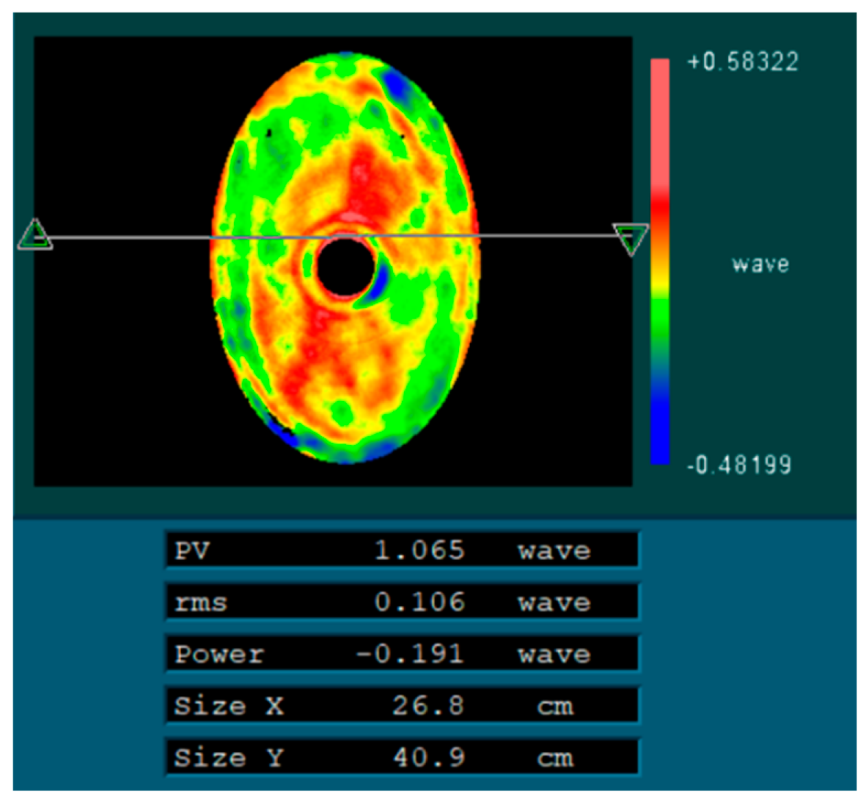
6.3. Gravity Deformation Verification Test
Since the mirror is tested in the horizontal direction of the optical axis, in order to verify the influence of gravity deformation on the static accuracy of the mirror, a method is used to flip the mirror 180° for the surface shape test. This method superimposes the effect of 2 g gravity and can use this gravity to evaluate the surface change in the mirror. After the flip, the surface accuracy of the mirror is 0.106 λ (λ = 632.8 nm). The test results are shown in
Figure 15 and validate the effectiveness of the model and finite element analysis.
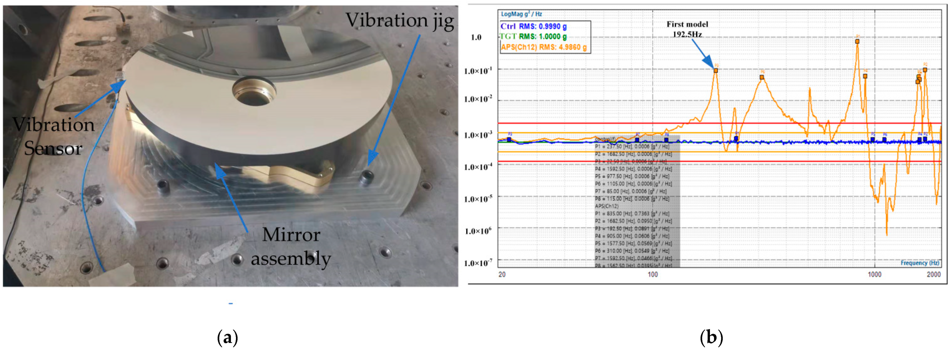
6.4. Vibration Test
After the single-point machining of the mirror component, a random vibration test was carried out, and the natural frequency of the mirror was tested, as shown in
Figure 16. The first-order mode of the mirror component was 192.5 Hz, and the error was within 4% of the finite element analysis result, which verified the reliability of the simulation results and a good dynamic stiffness.
7. Conclusions and Future Work
In order to solve the difficult challenge of achieving a very lightweight design of mirrors with a high steepness in an ultra-compact layout of space payload, an equivalent modeling method for the plate deformation of high-steepness elliptical mirrors is proposed in this paper. Guided by topology shape optimization, a lightweight mirror structure that can be quickly assembled is established. The error between the predicted results of the equivalent model and the finite element analysis results is within 10%. The experimental results show that the lightweight aluminum mirror with a high steepness shape accuracy is 1/10 λ (λ = 632.8 nm), and the surface roughness Ra is better than 3.342 nm. The vibration test shows that the dynamic stiffness of mirror is better than 192 Hz. This research provides a strong theoretical support and application prospect for the rapid manufacturing and application of a lightweight aluminum mirror with a high steepness.
Future research should focus on three main aspects. First of all, due to limitations of the project cycle and schedule, the surface shape accuracy and surface roughness of the mirror still need to be improved. In the future, attempts will be made to further reduce the low-frequency and high-frequency surface shape errors. Secondly, with the improvement of the mirror shape accuracy, the print-through effect of a high lightweight mirror will also increase, and the mediated frequency error will be hard to correct for the mirror with a higher shape accuracy. Future studies should focus on reducing the influence of the mirror footprint effect. Finally, with the improvement and application of additive manufacturing and topology optimization design theory, future research should introduce a lattice structure suitable for high-steepness mirrors to further increase the local stiffness of mirrors and gradually promote the application of visible light.
Author Contributions
Conceptualization, S.T. and X.Z.; methodology, S.T.; software, S.T.; validation, H.W., L.Y. and M.H.; formal analysis, S.T.; investigation, S.T.; resources, X.Z.; data curation, S.T.; writing—original draft preparation, S.T.; writing—review and editing, S.T., L.Y., L.W. and Q.F.; visualization, S.T.; supervision, L.W.; project administration, M.H.; funding acquisition, Q.F. All authors have read and agreed to the published version of the manuscript.
Funding
This work was supported by Funded by Youth Innovation Promotion Association of Chinese Academy of Sciences (2021221) and Jilin Province Science and Technology Development Project (No.20210508054RQ).
Institutional Review Board Statement
Not applicable.
Informed Consent Statement
Not applicable.
Data Availability Statement
Not applicable.
Acknowledgments
The authors thank the Key Laboratory of Manufacturing Technology, Chinese Academy of Sciences for the conditions. The authors also would like to thank the anonymous reviewers for their useful comments and critical remarks, which helped to improve this paper.
Conflicts of Interest
The authors declare no conflict of interest. We purchased the genuine software license of UG and stated the company name in our article. The funders had no role in the design of the study.
References
- Risse, S.; Beier, M.; Hartung, J. Aspherical and Freeform Mirrors Based on Ultra-Precise Manufacturing for Telescopes in the Vis Spectral Range. In Proceedings of the International Conference on Space Optics—ICSO 2016, Biarritz, France, 25 September 2017. [Google Scholar]
- Wu, K.-H.; Lie, C.-C.; Lin, Y.-C.; Chan, C.-Y.; Huang, T.-M.; Hsu, M.-Y. Assembly Aligning and Measuring of a Reflective Telescope Primary Mirror. In Proceedings of the International Society for Optical Engineering SPIE Optics + Photonics, San Diego, CA, USA, 28 September 2016. [Google Scholar]
- Kim, Y.; Hong, J.; Choi, B.; Lee, J.U.; Kim, Y.; Kim, H. Assembly and alignment method for optimized spatial resolution of off-axis three-mirror fore optics of hyperspectral imager. Opt. Express 2017, 25, 20817–20828. [Google Scholar] [CrossRef] [PubMed]
- Purll, D.; Lobb, D.; Barnes, A.; Talbot, R.G.; Rolt, S.; Robertson, D.; Closs, M.; te Plate, M. The Integral Field Unit for the James Webb Space Telescope’s Near-Infrared Spectrograph. In Proceedings of the 8th International Conference on Service Oriented Computing ICSOC, San Francisco, CA, USA, 7–10 December 2010. [Google Scholar]
- Peschel, T.; Beier, M.; Damm, C.; Hartung, J.; Jende, R.; Müller, S.; Rohde, M.; Gebhardt, A.; Risse, S.; Walter, I.; et al. Integration and Testing of an Imaging Spectrometer for Earth Observation. In Proceedings of the 16th International Conference on Service Oriented Computing ICSOC, Hangzhou, China, 12–15 November 2018. [Google Scholar]
- Thompson, S.; Doel, A.; Whalley, M.; Edeson, R.; Edeson, R.; Tosh, I.; Poyntz-Wright, O.; Atad-Ettedgui, E.; Montgomery, D.; Nawasra, J. Large aperture Telescope Technology: A Design for an Active Lightweight Multi-Segmented Fold-out Space Mirror. In Proceedings of the 8th International Conference on Service Oriented Computing ICSOC, San Francisco, CA, USA, 7–10 December 2010. [Google Scholar]
- Chang, S.-T.; Lin, Y.-C.; Lien, C.-C.; Huang, T.-M.; Tsay, H.-L.; Miau, J.-J. The design and assembly of a long-focal-length telescope with aluminum mirrors. In Proceedings of the 12th International Conference on Space Optics—ICSO 2018, Chania, Greece, 9–12 October 2018. [Google Scholar]
- Siegler, N.; Tong, E.C.; Batalha, N.; Fazio, G.G.; Lystrup, M.; MacEwen, H.A.; Allen, L.N.; Havey, K.; Mooney, T.; Knight, J.S.; et al. Material selection for far Infrared telescope mirrors. In Proceedings of the Space Telescopes and Instrumentation 2018: Optical, Infrared, and Millimeter Wave, Austin, TX, USA, 10–15 June 2018. [Google Scholar]
- Tan, S.; Ding, Y.; Xu, Y.; Shi, L. Design and fabrication of additively manufactured aluminum mirrors. Opt. Eng. 2020, 59, 013103. [Google Scholar] [CrossRef]
- Xie, X.; Xu, L.; Wang, Y.; Shen, L.; Fan, X.; Fan, W.; Li, C.; Zhao, H. Solving, analyzing, manufacturing, and experimental testing of thickness distribution for a cycloid-like variable curvature mirror. Opt. Express 2021, 29, 18010–18025. [Google Scholar] [CrossRef] [PubMed]
- Mouroulis, P.Z.; DeWitt Iv, F.; Smith, W.J.; Nadorff, G.; Naradikian, M.; Johnson, R.B. Self-weight distortion of lens elements. In Proceedings of the Current Developments in Lens Design and Optical Engineering VII, San Diego, CA, USA, 14–15 August 2006. [Google Scholar]
- Liu, S.; Hu, R.; Li, Q.; Zhou, P.; Dong, Z.; Kang, R. Topology optimization-based lightweight primary mirror design of a large-aperture space telescope. Appl. Opt. 2014, 53, 8318–8325. [Google Scholar] [CrossRef] [PubMed]
- Qin, T.; Guo, J.; Jing, Z.; Han, P.; Qi, B. Hybrid IPSO-IAGA-BPNN algorithm-based rapid multi-objective optimization of a fully parameterized spaceborne primary mirror. Appl. Opt. 2021, 60, 3031–3043. [Google Scholar] [CrossRef] [PubMed]
- Vukobratovich, D. Rugged yet lightweight: How can we achieve both in optical instruments? In Optomechanical Design: A Critical Review, Proceedings of the International Society for Optics and Photonics Conference SPIE, San Diego, CA, USA, 22–23 July 1992; Society of Photo Optical: Bellingham, WA, USA, 1992. [Google Scholar]
- Nelson, J.E.; Lubliner, J.; Mast, T.S. Telescope mirror supports: Plate deflections on point supports. In Advanced Technology Optical Telescopes I, Proceedings of the SPIE Astronomy Conferences, Tucson, AZ, USA, 8 March 1982; Society of Photo-Optical Instrumentation Engineers (SPIE): Tucson, AZ, USA, 1982; Volume 332, pp. 212–228. [Google Scholar]
- Vukobratovich, D.; Gerzoff, A.; Cho, M.K. Therm-optic analysis of bi-metallic mirrors. In Proceedings of the International Symposium on Optical Science, Engineering & Instrumentation, San Diego, CA, USA, 21 July–1 August 1997. [Google Scholar]
- Atkins, C.; Brzozowsk, W.; Dobson, N.; Milanova, M.; Nistea, I.T. Additively manufactured mirrors for CubeSats. In Proceedings of the SPIE Optical Engineering + Applications, San Diego, CA, USA, 11–15 August 2019. [Google Scholar]
- Stern, M.L.; Bari, J.M. Method for Fabricating Additive Manufactured Lightweight Metallic Mirrors. 2015. Available online: https://ntrl.ntis.gov/NTRL/dashboard/searchResults/titleDetail/AD1033942.xhtml (accessed on 1 September 2022).
- Da Deppo, V.; Pace, E.; Morgante, G.; Focardi, M.; Terraneo, M.; Zocchi, F.; Bianucci, G.; Micela, G. Study and realization of a prototype of the primary off-axis 1-m diameter aluminium mirror for the ESA ARIEL mission. In Proceedings of the 12th International Conference on Space Optics—ICSO 2018, Chania, Greece, 9–12 October 2018. [Google Scholar]
- Yoder, P.; Vukobratovich, D. Opto-Mechanical Systems Design, 4th ed.; CRC Press Taylor & Francis Group: Boca Raton, FL, USA, 2015; pp. 798–802. [Google Scholar]
- Horvath, N.; Davies, M. Advancing lightweight mirror design: A paradigm shift in mirror preforms by utilizing design for additive manufacturing. Appl. Opt. 2021, 60, 681–696. [Google Scholar] [CrossRef] [PubMed]
- Hwang, J. Optimal design and manufacturing of infrared surveillance camera mirror. In Proceedings of the IEEE International Conference on Nano/micro Engineered & Molecular Systems, Xiamen, China, 20–23 January 2010. [Google Scholar]
- Lemared, S.; Ferrari, M.; Du Jeu, C.; Dufour, T.; Soulier, N.; Hugot, E. Stress mirror polishing for future large lightweight mirrors: Design using shape optimization. Opt. Express 2020, 28, 14055–14071. [Google Scholar] [CrossRef] [PubMed]
- Liu, G.; Guo, L.; Wang, X.; Wu, Q. Topology and parametric optimization based lightweight design of a space reflective mirror. Opt. Eng. 2018, 57, 075101. [Google Scholar] [CrossRef]
- Yan, L.; Zhang, X.; Fu, Q.; Wang, L.; Shi, G.; Tan, S.; Zhang, K.; Liu, M. Assembly-level topology optimization and additive manufacturing of aluminum alloy primary mirrors. Opt. Express 2022, 30, 6258–6273. [Google Scholar] [CrossRef] [PubMed]
- Tan, S.; Li, Q.; Xu, Y.; Shen, H.; Cheng, Y.; Jia, P.; Xu, Y. Design and fabrication of lightweight additively manufactured mirrors for aviation. Appl. Opt. 2022, 61, 2198–2206. [Google Scholar] [CrossRef] [PubMed]
- Li, Z.; Chen, X.; Wang, S.; Jin, G. Optimal design of a Φ760 mm lightweight SiC mirror and the flexural mount for a space telescope. Rev. Sci. Instrum. 2017, 88, 125107. [Google Scholar] [CrossRef] [PubMed]
- Mutters, D.; Doyle, K.B.; Ellis, J.D. Mirror topology optimization. In Proceedings of the Optomechanical Engineering, San Diego, CA, USA, 11–15 August 2019. [Google Scholar]
- Burmeister, F.; Ehrhardt, S.; Benkenstein, T.; Lammers, T.; Harel, E. CGH for ESO’s ELT M2 reference plate: Fabrication of high precision CGHs. In Proceedings of the Advances in Optical and Mechanical Technologies for Telescopes and Instrumentation IV, Online, 14–22 December 2020. [Google Scholar]
Figure 1.
Optical system.
Figure 1.
Optical system.
Figure 2.
Flow chart of design scheme of a high-steepness lightweight elliptical mirror.
Figure 2.
Flow chart of design scheme of a high-steepness lightweight elliptical mirror.
Figure 3.
Equivalence of high-steepness circular mirror plate.
Figure 3.
Equivalence of high-steepness circular mirror plate.
Figure 4.
Radial plate equivalence of high-steepness elliptical mirror.
Figure 4.
Radial plate equivalence of high-steepness elliptical mirror.
Figure 5.
Typical lightweight unit: (a) triangular cell; (b) square cell; (c) hexagonal cell.
Figure 5.
Typical lightweight unit: (a) triangular cell; (b) square cell; (c) hexagonal cell.
Figure 6.
Elliptical initial structure converted by equivalent circular plate: (a) circular equivalent plate; (b) high-steepness elliptic mirror.
Figure 6.
Elliptical initial structure converted by equivalent circular plate: (a) circular equivalent plate; (b) high-steepness elliptic mirror.
Figure 7.
Establishment of initial finite element model for topology shape optimization: (a) division of optimization areas; (b) fixed support constraint.
Figure 7.
Establishment of initial finite element model for topology shape optimization: (a) division of optimization areas; (b) fixed support constraint.
Figure 8.
The optimization result at the threshold value 0.1 after 25 interactions.
Figure 8.
The optimization result at the threshold value 0.1 after 25 interactions.
Figure 9.
Final design structure of mirror: (a) lightweight schematic of mirror back; (b) schematic diagram of mirror back trimming.
Figure 9.
Final design structure of mirror: (a) lightweight schematic of mirror back; (b) schematic diagram of mirror back trimming.
Figure 10.
The fitting result of the mirror surface under 1 g gravity of the mirror: (a) radial direction (X) surface accuracy; (b) radial direction (Y) surface accuracy; (c) Axial direction (Z) surface accuracy.
Figure 10.
The fitting result of the mirror surface under 1 g gravity of the mirror: (a) radial direction (X) surface accuracy; (b) radial direction (Y) surface accuracy; (c) Axial direction (Z) surface accuracy.
Figure 11.
The result of model analysis: (a) first order; (b) second order; (c) third order.
Figure 11.
The result of model analysis: (a) first order; (b) second order; (c) third order.
Figure 12.
Surface shape test of the mirror: (a) light path of test; (b) CGH area division.
Figure 12.
Surface shape test of the mirror: (a) light path of test; (b) CGH area division.
Figure 13.
Test results of mirror surface quality: (a) low−frequency error; (b) high−frequency error.
Figure 13.
Test results of mirror surface quality: (a) low−frequency error; (b) high−frequency error.
Figure 14.
Post polishing test results of mirror surface quality: (a) low-frequency error; (b) high-frequency error.
Figure 14.
Post polishing test results of mirror surface quality: (a) low-frequency error; (b) high-frequency error.
Figure 15.
Shape error test results of mirror rotation 180°.
Figure 15.
Shape error test results of mirror rotation 180°.
Figure 16.
Vibration test of mirror: (a) installation of sensor measuring points; (b) test results.
Figure 16.
Vibration test of mirror: (a) installation of sensor measuring points; (b) test results.
Table 1.
Requirement of main mirror index.
Table 1.
Requirement of main mirror index.
| Index Parameters | Requirement |
|---|
| shape | elliptical mirror |
| radius of curvature (mm) | 433 |
| conic | −1 |
| F number | long axis: 0.53
short axis: 0.70 |
| mass | <3.5 kg |
| first order model (Hz) | ≥180 Hz |
| surface accuracy requirement (RMS) | 1/10 λ (λ = 632.8 nm) |
| surface roughness (nm) | <5 nm |
Table 2.
Comparison of method accuracy.
Table 2.
Comparison of method accuracy.
| Method | Self-Weight Deflection | The Relative Error |
|---|
| Equivalent modeling | 31.64 nm | 8.3% |
| Finite element analysis (FEA) | 34.5 nm | Base |
Table 3.
Model participation factors in the first three modes.
Table 3.
Model participation factors in the first three modes.
| Mode Frequency | 200.4 Hz | 260.8 Hz | 392.4 Hz |
|---|
| X-TRANS | 3.791 × 10⁻¹ | 1.407 × 10⁻³ | 7.869 × 10⁻⁴ |
| Y-TRANS | 1.276 × 10⁻³ | 4.303 × 10⁻¹ | 1.724 × 10⁻³ |
| Z-TRANS | 2.602 × 10⁻² | 1.181 × 10⁻³ | 1.000 |
| X-ROTAT | 3.545 × 10⁻³ | 1.000 | 9.123 × 10⁻⁴ |
| Y-ROTAT | 1.000 | 3.479 × 10⁻³ | 3.022 × 10⁻³ |
| Z-ROTAT | 2.627 × 10⁻⁵ | 2.813 × 10⁻⁴ | 1.907 × 10⁻⁴ |
| Publisher’s Note: MDPI stays neutral with regard to jurisdictional claims in published maps and institutional affiliations. |
© 2022 by the authors. Licensee MDPI, Basel, Switzerland. This article is an open access article distributed under the terms and conditions of the Creative Commons Attribution (CC BY) license (https://creativecommons.org/licenses/by/4.0/).


 ,
, 


