
The AlfaCrux CubeSat Mission Description and Early Results
 , ,
, ,  , , ,
, , ,
Abstract
:1. Introduction
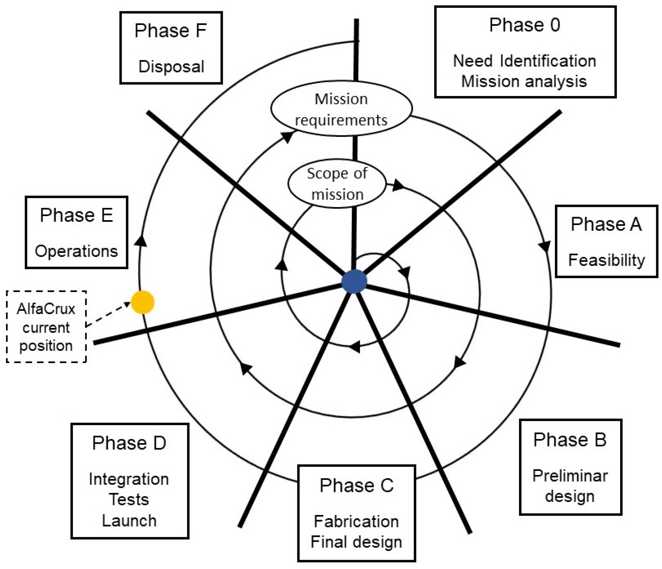
Educational Mission
- Phase 0—Mission analysis and needs identification: definition of the user needs and requirements, identification of systems concepts;
- Phase A—Feasibility: validation of the stakeholders requirements, identification of solutions that meet the requirements, definition of the mission architecture;
- Phase B—Preliminary design: definition of preliminary system design, validation solutions based on mission requirements;
- Phase C—Final design and Fabrication: definition of final system design (ground and space segments), system breakdown into subsystems;
- Phase D—Integration, Tests, and Launch: integration, tests and launch of the system;
- Phase E—Operations: operation and maintenance of the system to conduct the mission;
- Phase F—Disposal: planning of decommissioning and disposal.
- The mission life cycle;
- The functional requirements and physical architecture of the system;
- The assembly and integration of the systems components;
- The verification and validation process throughout the system development;
- Orbital dynamics, attitude determination and control;
- Elementary concepts of systems engineering.
2. Methods and Materials
2.1. Mission Description
2.1.1. User Needs
- Launch, operate, command, and control an amateur radio satellite.
- Provide a communication application to interact with the amateur radio community (demonstration of digital data repeater system).
- Provide communication between users and a set of generic data platforms (demonstration of data store-and-forward system).
- Implement and run an online open access database of in-orbit data for general investigations.
- Analyze narrow-band signal attenuation due to the effect of ionospheric scintillation (critical in low latitude regions, as in the case of Brazil).
- Analyze the satellite dynamic based on computer simulations and in-orbit data for studies and validation of Attitude Determination and Control System (ADCS) solutions and applications.
- Analyze and investigate digital twin modeling for aerospace applications.
2.1.2. Mission Concept
- Digipeater for amateurs radio data transfer;
- User-developed scientific applications based on GNU Radio libraries for communication channel characterization;
- Data relay for real-time communication between terminals in the same area.
- The satellite transmits beacons while orbiting the Earth, sending telemetry information.
- When the satellite passes through the ground station, the operation team verifies and set the proper operational mode, as well as schedules the next services to be available for the users. This information is available online in the AlfaCrux mission planner.
- When the store-and-forward service is available, a user terminal receives the beacon and sends the available information to the satellite. The satellite, in turn, will transmit the stored information to it.
- The satellite can send the received information in real time to another user terminal or ground station that is in the same area.
- When the satellite passes through a ground station, it exchanges messages from the collected user terminals and those that the system has for the terminals.
- The users will be able to interact with the system through the online official web page, receiving messages from their terminals or delivering the data they wish.
- When the digipeater service is available, the users can exchange digital data when they are in the footprint of the satellite. The current service available is the Automatic Packet Reporting System (http://www.aprs.org, accessed on 20 September 2022), an amateur radio-based system for real time digital communications of information of immediate value in the local area.
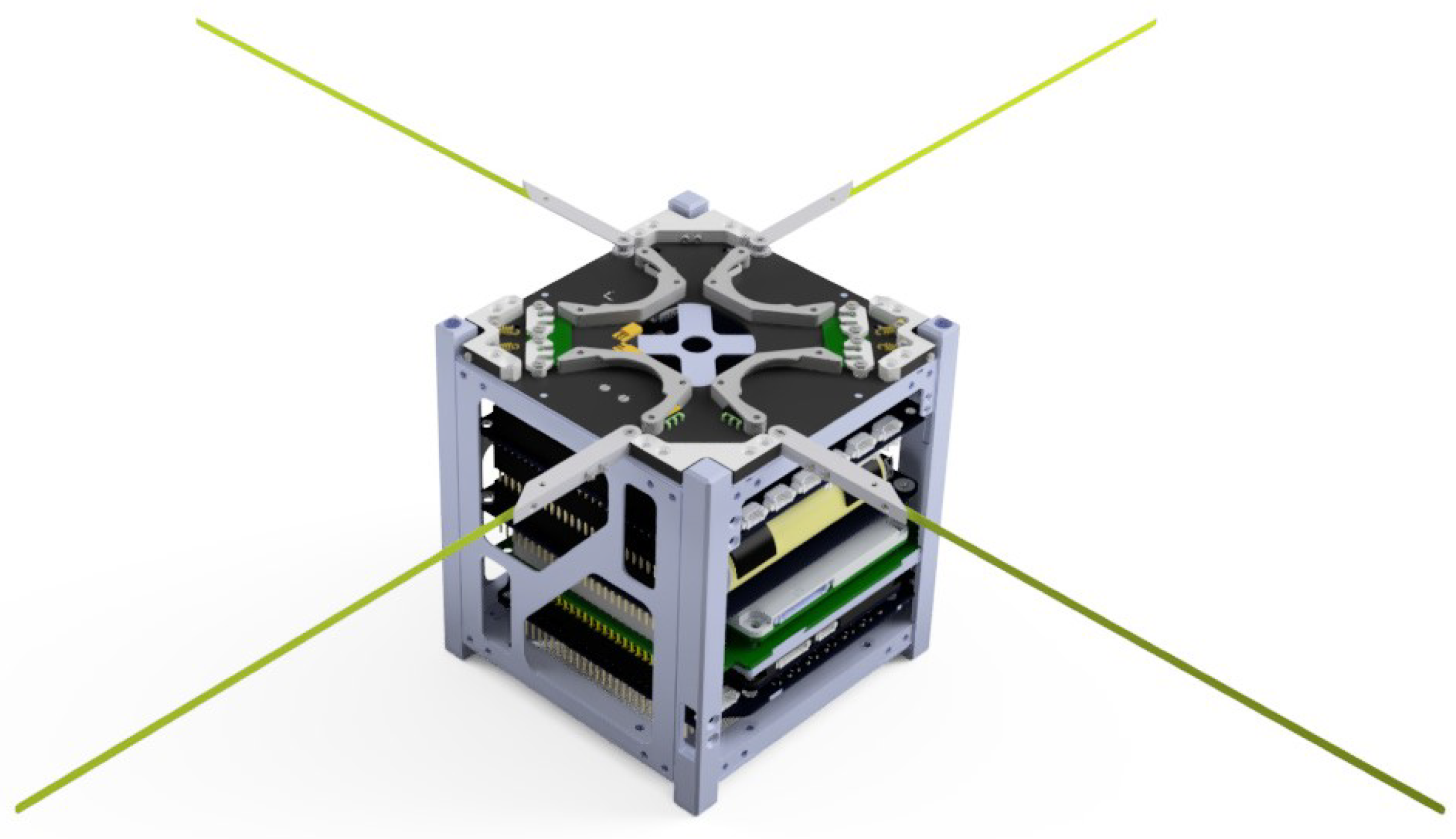
2.2. Alfacrux Spacecraft
- Satellite name: AlfaCrux;
- NORAD ID: 52160;
- International Designator (INTLDES): 2022-033D;
- Country: BRAZ;
- Launch: 1 April 2022;
- Site: Air Force Eastern Test Range;
- Radar cross-section (RCS): Small;
- Period: 94.64 min;
- Inclination: 97.39º;
- Apogee: 508 km;
- Perigee: 494 km.
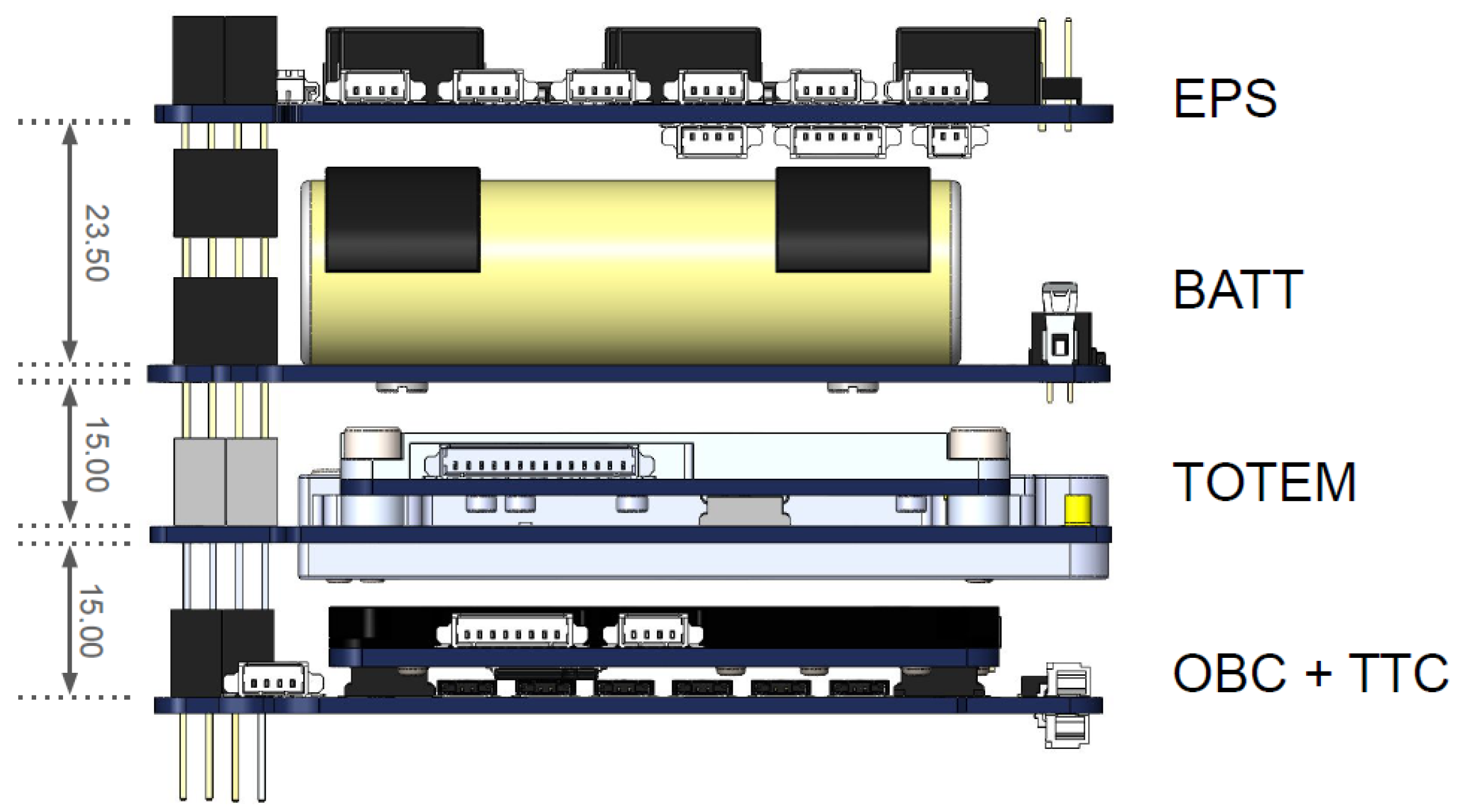
2.2.1. Alfacrux Subsystems
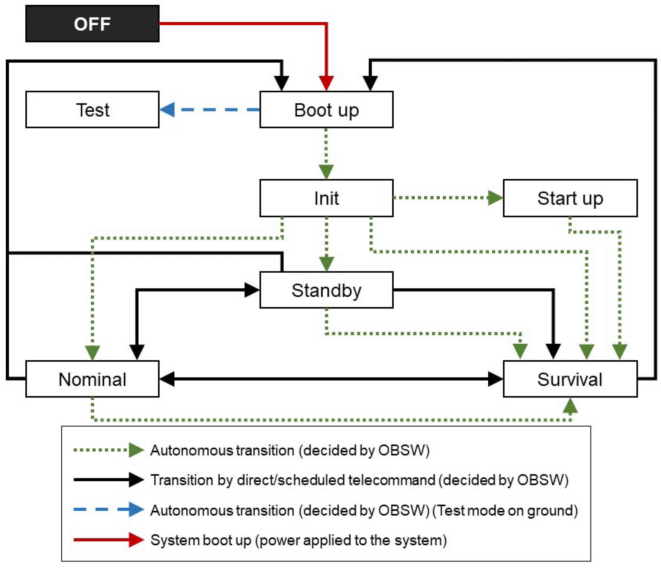
2.2.2. Operational Modes
- Boot-up: During the first boot up of the system, the software shall execute a sequence of first tests and actions, including health check and memories and file system initialization. These actions shall be executed only once. After the completion of the boot up actions, the satellite shall enter Init mode and continue.
- Init: In this mode, the software checks if the antenna was deployed. If not, it shall immediately enter Startup mode; further health checks will be executed once the antenna is deployed.
- Startup: The main objective of this mode is to deploy the antenna and to move to Survival mode once the antenna deployment sequence finalizes. This mode will also collect telemetry from the first minutes of the mission. The antennas shall be autonomously deployed by the onboard software 30 min after ejection. At the end of the antenna deployment sequence, the TTC is configured to allow transmissions. The file system will not be enabled in Startup to avoid errors that could avoid the completion of the Startup sequence. It will be enabled after the completion of Startup, just before the change to Survival mode.
- Survival: This mode is intended to be the fallback mode in case of critical problems. This mode shall have a positive power budget and shall guarantee the possibility to access the satellite from ground. Payloads and non-critical subsystems are turned off in this mode. A beacon with basic health information is transmitted periodically to ease the location of the satellite and to provide a first assessment of its status. TTC is configured with its default configuration. The only way to exit Survival mode is to set a mode change by telecommand (TM) and reboot the software.
- Nominal: The main tasks for the mission execution are performed in Nominal mode. Payloads are allowed to operate in this mode, providing a digital data repeater at 437.225 MHz based on AX.25 protocol, and also a store-and-forward service at 437.125 MHz using Gaussian Minimum Shift Keying modulation. The main scheduler will be in charge of the execution of the different tasks. Health checks are executed periodically. If a critical problem is found, the software will change to Survival mode autonomously.
2.2.3. User Interface with OSI Layers
- B1-OBC: telemetry from the main on-board computer;
- B2-EPS: telemetry from the electric power subsystem;
- B3-TTC: telemetry from the telemetry and telecommand subsystem;
- B4-UHF: telemetry from the antenna deployment subsystem;
- B5-Temps: temperature telemetry of different subsystems of the satellite.
2.3. Alfacrux Ground Segment
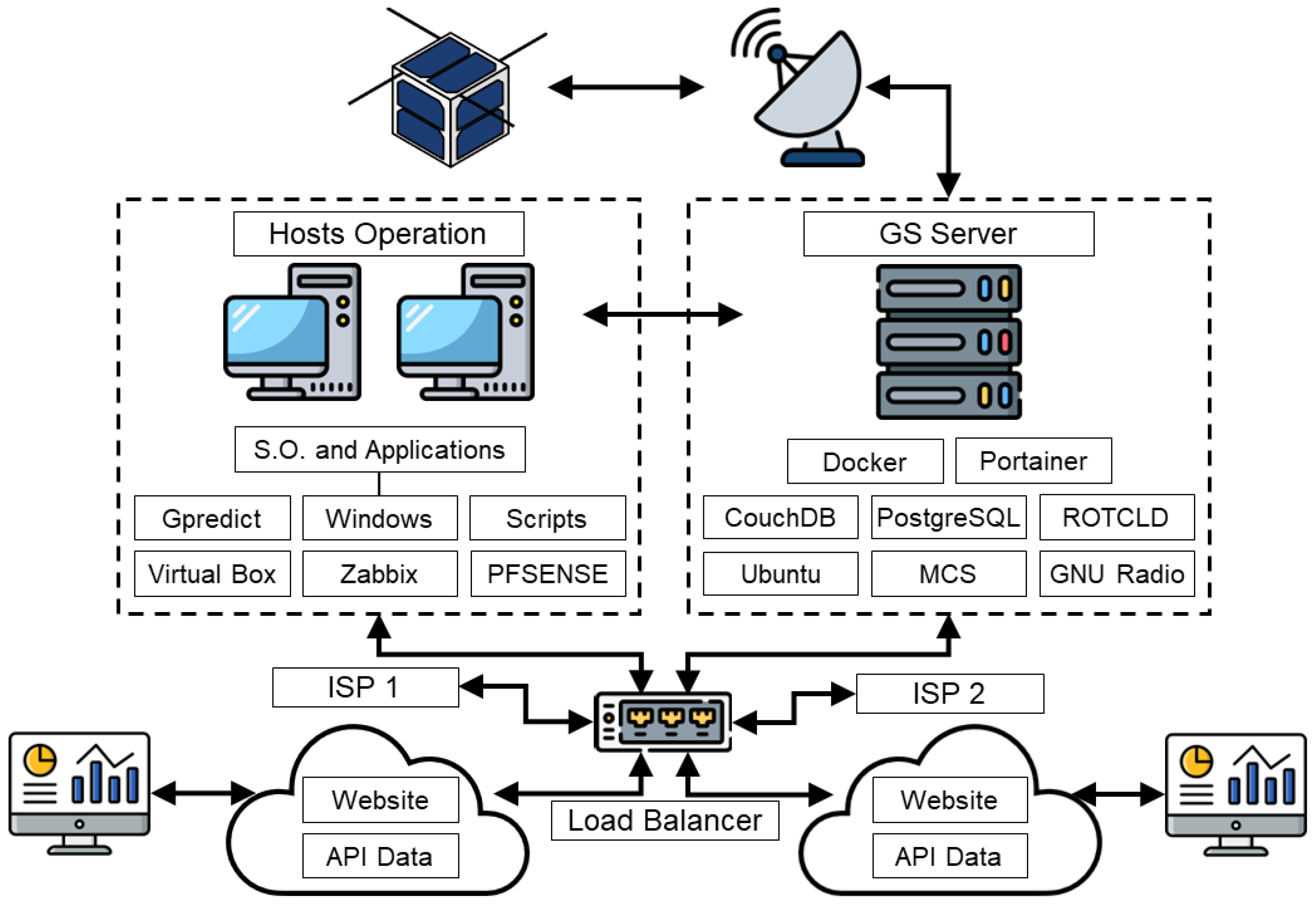
2.3.1. Ground Station Architecture
- Two desktop computers, with I5 CPU, 8 GB of RAM, and 500 GB SATA Hard Disk;
- One Dell server with Intel(R) Xeon(R) E-2224 CPU @ 3.40GHz, 8 GB of RAM, and 1 TB SATA Hard Disk;
- One load balancer, which allows balancing the links to the Internet;
- CAT 6 A cabling, used to interconnect computers, servers, and load balancer;
- Scripts for automation;
- One uninterruptible power source (UPS), which allows system autonomy for about 35 min without power from the electrical grid.
- Computers or operating stations: its purpose is to operate and control the software-defined-radio and antenna rotors using an orbit propagator and Doppler shift calculator along with the mission control software (MCS). The VirtualBox was installed for extra functions such as virtual private network (VPN) and monitoring with Zabbix. Some examples of monitored parameters are processing load, RAM memory consumption, and SWAP memory consumption, among others.
- Server dedicated to the subsystems necessary for antenna control and Doppler correction. It aims to provide the necessary hardware resources for Rotcld, a Hamlib rotator control daemon, and MCS applications.
- General-purpose scripts to automate internal operation tasks.
2.3.2. User Segment
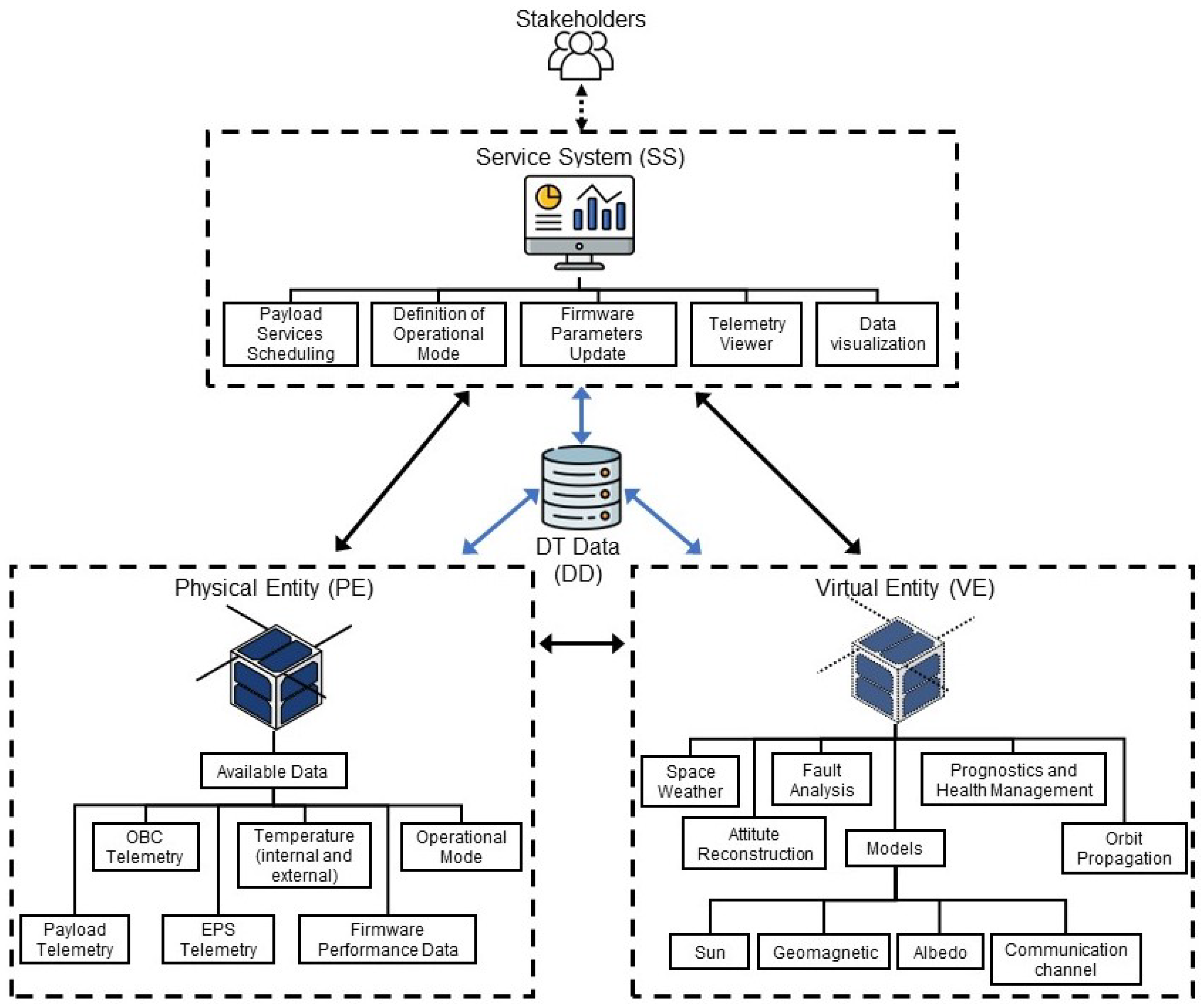
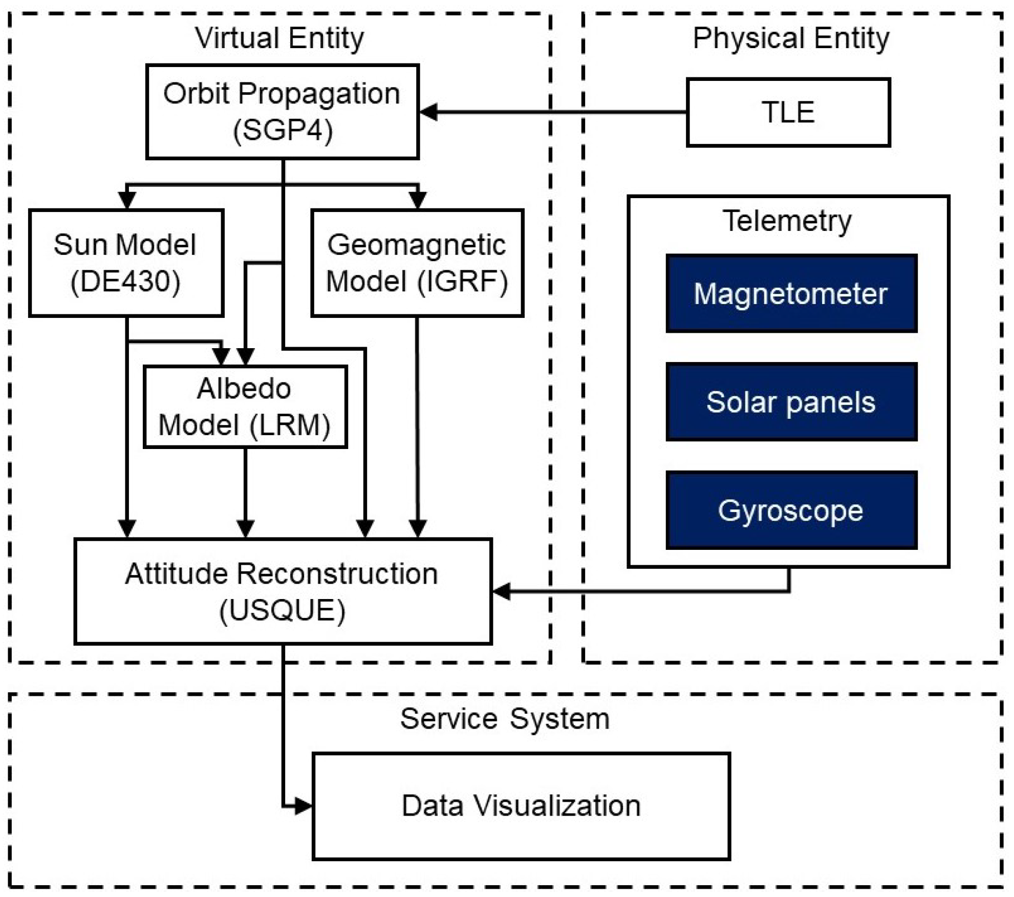
2.4. Alfacrux Digital Twin Architecture
- Physical entity: acquires measurements of the magnetometer, solar panels, and gyroscope, and the two-line elements (TLE);
- Virtual entity: uses the Sun, Geomagnetic, and Albedo models; the orbit propagation; and the telemetry data to reconstruct the satellite attitude;
- Connection: responsible for the data collection and management system;
- Service system: responsible for the attitude visualization.
3. Results and Discussions
3.1. Satellite and Ground Station Commissioning
3.2. Alfacrux Digital Twin Pilot
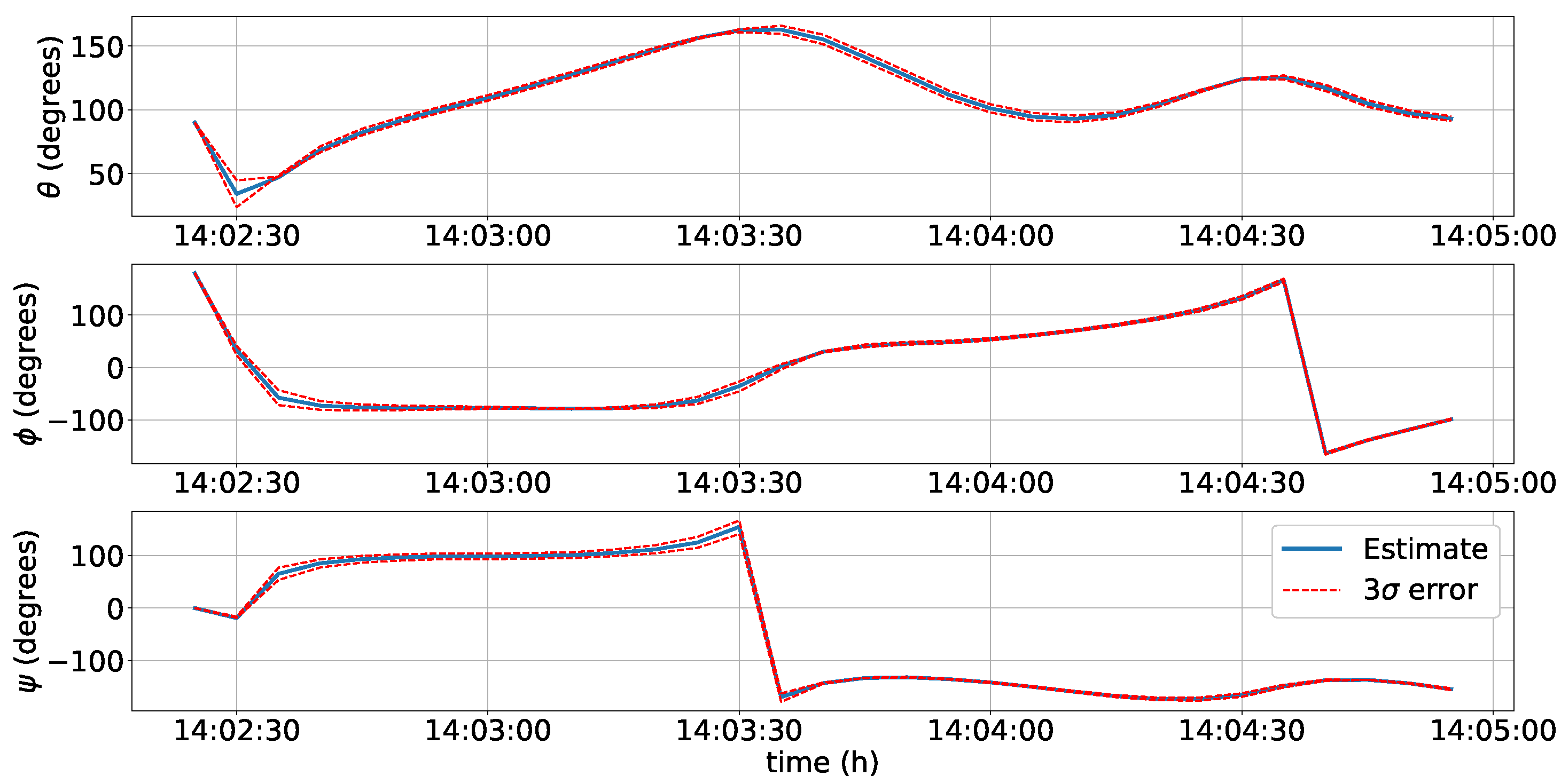
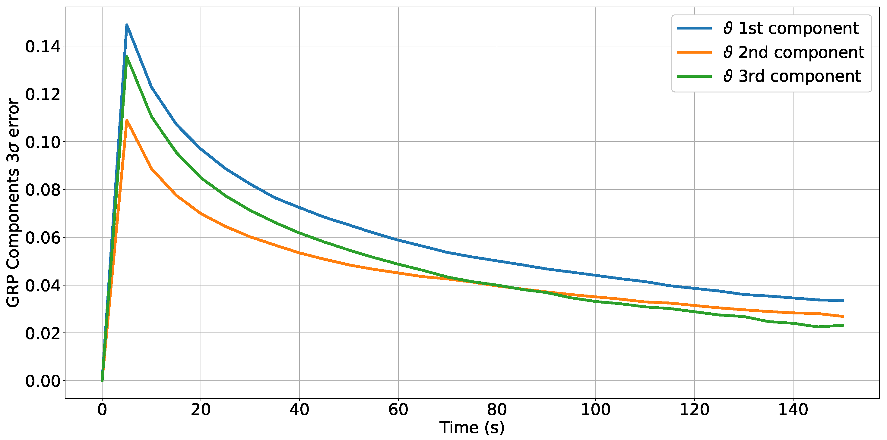
3.2.1. Attitude Reconstruction and Dynamic Analysis
3.2.2. Environment Models
3.2.3. A Preliminary Outcome Example
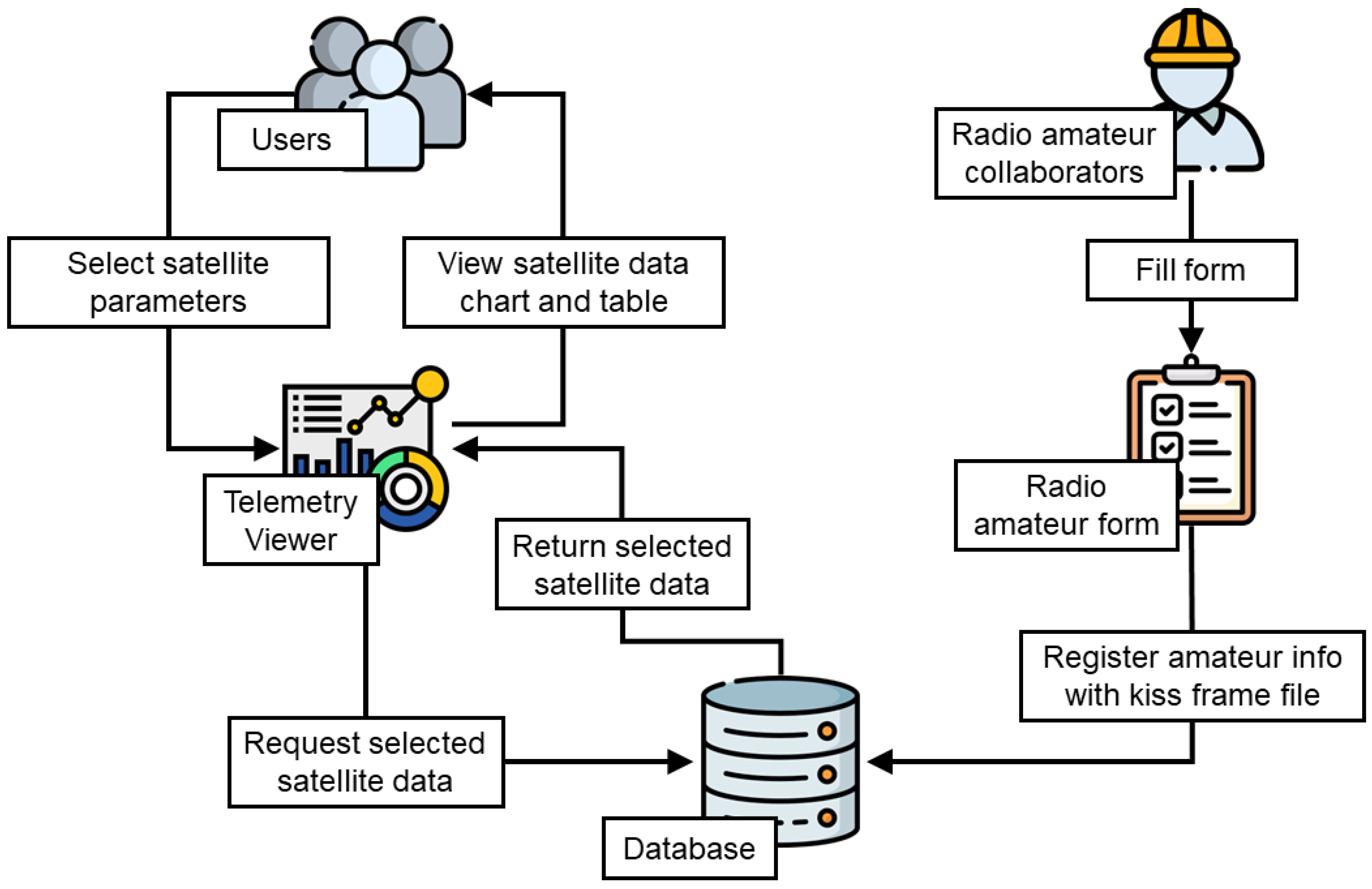
3.2.4. Data Management and Telemetry Viewer
3.2.5. Communication Channel Modeling and Risk Analysis
4. Conclusions
Author Contributions
Funding
Data Availability Statement
Acknowledgments
Conflicts of Interest
References
- Suhadis, N.M. Statistical overview of CubeSat mission. In Proceedings of the International Conference of Aerospace and Mechanical Engineering 2019, Penang, Malaysia, 20–21 November 2019; Springer: Berlin/Heidelberg, Germany, 2020; pp. 563–573. [Google Scholar]
- Kopacz, J.R.; Herschitz, R.; Roney, J. Small satellites an overview and assessment. Acta Astronaut. 2020, 170, 93–105. [Google Scholar] [CrossRef]
- Villela, T.; Costa, C.A.; Brandão, A.M.; Bueno, F.T.; Leonardi, R. Towards the Thousandth CubeSat: A Statistical Overview. Int. J. Aerosp. Eng. 2019, 2019, 5063145. [Google Scholar] [CrossRef]
- National Academies of Sciences, Engineering, and Medicine. In Achieving Science with CubeSats: Thinking Inside the Box; The National Academies Press: Washington, DC, USA, 2016.
- Cappelletti, C.; Battistini, S.; Malphrus, B.K. CubeSat Handbook—From Mission Design to Operations; Elsevier: Amsterdam, The Netherlands, 2020. [Google Scholar]
- Pelton, J.N.; Madry, S. Handbook of Small Satellites—Technology, Design, Manufacture, Applications, Economics and Regulation; Springer: Berlin/Heidelberg, Germany, 2020. [Google Scholar]
- Pelton, J.N.; Madry, S.; Lara, S.C. Handbook of Satellite Applications, 2nd ed.; Springer: Berlin/Heidelberg, Germany, 2017. [Google Scholar]
- Chin, A.; Coelho, R.; Nugent, R.; Munakata, R.; Suari, J.P. CubeSat: The Pico-Satellite Standard for Research and Education. In Proceedings of the AIAA Space 2008 Conference and Exhibition, San Diego, CA, USA, 9–11 September; American Institute of Aeronautics and Astronautics: Reston, VA, USA, 2008. [Google Scholar]
- Kang, J.; Gregory, J.; Temkin, S.; Sanders, M.; King, J. Creating future space technology workforce utilizing CubeSat platforms: Challenges, good practices, and lessons learned. In Proceedings of the AIAA Scitech 2021 Forum, Online, 11–15 January 2021; American Institute of Aeronautics and Astronautics: Reston, VA, USA, 2021. [Google Scholar]
- Cervone, A.; Topputo, F.; Speretta, S.; Menicucci, A.; Turan, E.; Di Lizia, P.; Massari, M.; Franzese, V.; Giordano, C.; Merisio, G.; et al. LUMIO: A CubeSat for observing and characterizing micro-meteoroid impacts on the Lunar far side. Acta Astronaut. 2022, 195, 309–317. [Google Scholar] [CrossRef]
- Baker, J.; Colley, C.N.; Essmiller, J.C.; Klesh, A.T.; Krajewski, J.A.; Sternberg, D.C. MarCO: The First Interplanetary CubeSats. In Proceedings of the EPSC-DPS Joint Meeting 2019, Geneva, Switzerland, 15–20 September 2019; Volume 13. Abstract Number #EPSC–DPS2019–2009. [Google Scholar]
- Walker, R.; Binns, D.; Bramanti, C.; Casasco, M.; Concari, P.; Izzo, D.; Feili, D.; Fernandez, P.; Fernandez, J.G.; Hager, P.; et al. Deep-space CubeSats: Thinking inside the box. Astron. Geophys. 2018, 59, 5.24–5.30. [Google Scholar] [CrossRef]
- Kodheli, O.; Lagunas, E.; Maturo, N.; Sharma, S.K.; Shankar, B.; Montoya, J.F.M.; Duncan, J.C.M.; Spano, D.; Chatzinotas, S.; Kisseleff, S.; et al. Satellite Communications in the New Space Era: A Survey and Future Challenges. IEEE Commun. Surv. Tutorials 2021, 23, 70–109. [Google Scholar] [CrossRef]
- Saeed, N.; Elzanaty, A.; Almorad, H.; Dahrouj, H.; Al-Naffouri, T.Y.; Alouini, M.S. CubeSat communications: Recent advances and future challenges. IEEE Commun. Surv. Tutorials 2020, 22, 1839–1862. [Google Scholar] [CrossRef]
- Straub, J.; Marsh, R.A.; Whalen, D.J. Small Spacecraft Development Project-Based Learning, 1st ed.; Springer International Publishing: Basel, Switzerland, 2017. [Google Scholar]
- Castaldi, P.; Mimmo, N. An experience of project based learning in aerospace engineering. IFAC-PapersOnLine 2019, 52, 484–489. [Google Scholar] [CrossRef]
- Honore-Livermore, E.; Birkeland, R. Managing product development and integration of a university CubeSat in a locked down world. In Proceedings of the 2021 IEEE Aerospace Conference (50100), Big Sky, MT, USA, 6–13 March 2021. [Google Scholar]
- Thomas, J.W. A Review of Research on Project-Based Learning 2000; The Autodesk Foundation: San Rafael, CA, USA, 2010. [Google Scholar]
- ECSS-EST-10C Rev. 1; Space Engineering-System Engineering General Requirements. ESA Requirements and Standards Division: Noordwijk, The Netherlands, 2017.
- Hirshorn, S.R.; Voss, L.D.; Bromley, L.K. Nasa Systems Engineering Handbook; Technical Report; NASA: Washington, DC, USA, 2017. [Google Scholar]
- Glaessgen, E.H.; Stargel, D.S. The digital twin paradigm for future NASA and U.S. Air force vehicles. In Proceedings of the Collection of Technical Papers—AIAA/ASME/ASCE/AHS/ASC Structures, Structural Dynamics and Materials Conference, Honolulu, HI, USA, 23–26 April 2012; pp. 1–14. [Google Scholar] [CrossRef]
- Li, L.; Aslam, S.; Wileman, A.; Perinpanayagam, S. Digital Twin in Aerospace Industry: A Gentle Introduction. IEEE Access 2022, 10, 9543–9562. [Google Scholar] [CrossRef]
- Kontaxoglou, A.; Tsutsumi, S.; Khan, S.; Nakasuka, S. Towards a Digital Twin Enabled Multifidelity Framework for Small Satellites. In Proceedings of the PHM Society European Conference, Jeju, Korea, 8–10 September 2021; Volume 6, p. 10. [Google Scholar]
- Capon, C.; Lorrain, P.; Smith, B.; Brown, M.; Kurtz, J.; Boyce, R. Numerical Predictions for On-Orbit Ionospheric Aerodynamics Torque Experiment. In Proceedings of the 2020 IEEE Aerospace Conference, Big Sky, MT, USA, 7–14 March 2020; pp. 1–12. [Google Scholar]
- Tao, F.; Zhang, M.; Liu, Y.; Nee, A. Digital twin driven prognostics and health management for complex equipment. CIRP Ann. 2018, 67, 169–172. [Google Scholar] [CrossRef]
- Tao, F.; Zhang, H.; Liu, A.; Nee, A.Y.C. Digital Twin in Industry: State-of-the-Art. IEEE Trans. Ind. Inform. 2019, 15, 2405–2415. [Google Scholar] [CrossRef]
- Markley, F.; Crassidis, J. Fundamentals of Spacecraft Attitude Determination and Control; Space Technology Library; Springer: New York, NY, USA, 2014. [Google Scholar]
- Crassidis, J.L.; Markley, F.L. Unscented Filtering for Spacecraft Attitude Estimation. J. Guid. Control. Dyn. 2003, 26, 536–542. [Google Scholar] [CrossRef]
- da Silva, R.C.; Ishioka, I.S.; Cappelletti, C.; Battistini, S.; Borges, R.A. Helmholtz cage design and validation for nanosatellites HWIL testing. IEEE Trans. Aerosp. Electron. Syst. 2019, 55, 3050–3061. [Google Scholar] [CrossRef]
- da Silva, R.C.; Guimarães, F.C.; Loiola, J.V.L.; Borges, R.A.; Battistini, S.; Cappelletti, C. Tabletop testbed for attitude determination and control of nanosatellites. J. Aerosp. Eng. 2019, 32, 04018122. [Google Scholar] [CrossRef]
- da Silva, R.C.; Borges, R.A.; Battistini, S.; Cappelletti, C. A review of balancing methods for satellite simulators. Acta Astronautica 2021, 187, 537–545. [Google Scholar] [CrossRef]
- Vallado, D.A. Fundamentals of Astrodynamics and Applications, 4th ed.; Space technology Library, Microcosm Press: Hawthorne, CA, USA, 2013. [Google Scholar]
- Bhanderi, D.; Bak, T. Modeling Earth Albedo for Satellites in Earth Orbit. In Proceedings of the AIAA Guidance, Navigation, and Control Conference and Exhibit, San Francisco, CA, USA, 15–18 August 2005. [Google Scholar] [CrossRef]
- Ferreira, A.A.; Borges, R.A.; Reis, L.R.; Borries, C.; Vasylyev, D. Investigation of Ionospheric Effects in the Planning of the AlfaCrux UHF Satellite Communication System. IEEE Access. 2022, 10, 65744–65759. [Google Scholar] [CrossRef]


| Parameter | Value | Tolerance | Unit |
|---|---|---|---|
| Mass | 1.0650 | +/−5 g | kg |
| Center of gravity | x = 52.27, y = 50.81, z = 61.81 | +/−10% | mm |
| Moment of Inertia | I = 0.00183508557, I = 0.00185284505, I = 0.00184586679 | +/−10% | kgm |
| Product of Inertia | I = −0.00000456992, I = 0.00000153435, I = 0.00000877987 | +/−10% | kgm |
| Subsystem | Description |
|---|---|
| Electric Power System (EPS) | 3V3, 5V, and VBAT rails. Six switchable power outputs. Latch-up and over-current protection. Watchdog for monitoring GS contact. |
| Battery | 4 × Li-Ion cells ( 40 Wh). Integrated heaters. |
| Payload | Alén Space TOTEM-SDR with UHF 437 MHz front-end. |
| Onboard Computer (OBC) | AVR32 MCU; 128 MB Flash; RTC; I2C, CAN and UART. Three-axis gyroscope. Three-axis magnetometer. |
| Telemetry, Tracking, and Control (TTC) | UHF 435–438 MHz; Forward error correction, 30 dBm output, 4.8/9.6 kbps. |
| Parameter | Description |
|---|---|
| Modulation | Gaussian Minimum Shift Keying. |
| Bitrate | 4800/9600 bps. |
| Sync word | 0x930B51DE. |
| Frame format | ASM+Golay (AX100 mode 5). |
| Bit encoding | NRZ, most significant bit first. |
| Data randomization | Consultative Committee for Space Data Systems (CCSDS) randomization. |
| Error-correcting code | Reed-Solomon (255, 223). |
| Access | Start Time (UTC) | Stop Time (UTC) | Duration (s) |
|---|---|---|---|
| 1 | 2 April 2022 01:14:35.727 | 2 April 2022 01:19:56.946 | 321.218 |
| 2 | 2 April 2022 02:46:49.656 | 2 April 2022 02:55:04.360 | 494.704 |
| 3 | 2 April 2022 13:12:37.268 | 2 April 2022 13:19:58.469 | 441.201 |
| 4 | 2 April 2022 14:46:26.445 | 2 April 2022 14:53:21.925 | 415.480 |
| 5 | 3 April 2022 02:28:02.961 | 3 April 2022 02:37:04.707 | 541.746 |
| 6 | 3 April 2022 12:55:30.532 | 3 April 2022 13:00:24.969 | 294.438 |
| 7 | 3 April 2022 14:27:14.360 | 3 April 2022 14:35:37.980 | 503.620 |
| 8 | 4 April 2022 02:09:32.490 | 4 April 2022 02:18:45.596 | 553.106 |
| 9 | 4 April 2022 14:08:27.400 | 4 April 2022 14:17:31.124 | 543.724 |
Publisher’s Note: MDPI stays neutral with regard to jurisdictional claims in published maps and institutional affiliations. |
© 2022 by the authors. Licensee MDPI, Basel, Switzerland. This article is an open access article distributed under the terms and conditions of the Creative Commons Attribution (CC BY) license (https://creativecommons.org/licenses/by/4.0/).
Share and Cite
Borges, R.A.; dos Santos, A.C.; Silva, W.R.; Aguayo, L.; Borges, G.A.; Karam, M.M.; de Sousa, R.B.; García, B.F.-A.; Botelho, V.M.d.S.; Fernández-Carrillo, J.M.; et al. The AlfaCrux CubeSat Mission Description and Early Results. Appl. Sci. 2022, 12, 9764. https://0-doi-org.brum.beds.ac.uk/10.3390/app12199764
Borges RA, dos Santos AC, Silva WR, Aguayo L, Borges GA, Karam MM, de Sousa RB, García BF-A, Botelho VMdS, Fernández-Carrillo JM, et al. The AlfaCrux CubeSat Mission Description and Early Results. Applied Sciences. 2022; 12(19):9764. https://0-doi-org.brum.beds.ac.uk/10.3390/app12199764
Chicago/Turabian StyleBorges, Renato Alves, Andrea Cristina dos Santos, William Reis Silva, Leonardo Aguayo, Geovany Araújo Borges, Marcelo Monte Karam, Rogério Baptista de Sousa, Bibiano Fernández-Arruti García, Vitor Manuel de Sousa Botelho, José Manuel Fernández-Carrillo, and et al. 2022. "The AlfaCrux CubeSat Mission Description and Early Results" Applied Sciences 12, no. 19: 9764. https://0-doi-org.brum.beds.ac.uk/10.3390/app12199764