Article

6G Network Architecture Using FSO-PDM/PV-OCDMA System with Weather Performance Analysis

1
Department of Electronics and Communication Engineering, University Institute of Engineering, Chandigarh University, Mohali 140413, Punjab, India
2
Department of Electrical Engineering, UiT The Arctic University of Norway, 8514 Narvik, Norway
3
Department of Electrical Engineering, College of Engineering, Jouf University, Sakaka 72388, Saudi Arabia
4
Alexandria Higher Institute of Engineering and Technology, Alexandria 21311, Egypt
*
Authors to whom correspondence should be addressed.
Submission received: 16 September 2022 / Revised: 1 November 2022 / Accepted: 4 November 2022 / Published: 9 November 2022
(This article belongs to the Special Issue Photonic Technologies and Systems Enabling 6G)

Abstract

:
This paper presents a novel 160 Gbps free space optics (FSO) communication system for 6G applications. Polarization division multiplexing (PDM) is integrated with an optical code division multiple access (OCDMA) technique to form a PDM-OCDMA hybrid. There are two polarization states: one is X-polarization generated from adjusting the azimuthal angle of a light source at 0° while the other is Y-polarization which is generated by adjusting the azimuthal angle of a light source at 90°. Each polarization state is used for the transmission of four independent users. Each channel is assigned by permutation vector (PV) codes and carries 20 Gbps data. Four different weather conditions are considered for evaluating the performance of our proposed model. These weather conditions are clear air (CA), foggy conditions (low fog (LF), medium fog (MF), and heavy fog (HF)), dust storms (low dust storm (LD), moderate dust storm (MD), heavy dust storm (HD)), and snowfall (wet snow (WS) and dry snow (DS)). Bit error rate (BER), Q-factors, maximum propagation range, channel capacity, and eye diagrams are used for evaluating the performance of the proposed model. Simulation results assure successful transmission of 160 Gbps overall capacity for eight channels. The longest FSO range is 7 km which occurred under CA while the minimum is achieved under HD, which is 0.112 km due to large attenuation caused by HD. Within fog conditions, the maximum propagation distances are 1.525 km in LF, 1.05 km in MF, and 0.85 km in HF. Likewise, under WS and DS, the proposed system can support transmission distances of 1.15 km and 0.28 km, respectively. All these transmission distances are achieved at BER less than 10−5.

1. Introduction

Free space optical communication (FSO) is a wireless optical communication that can be used as an alternative to the existing radio frequency (RF) infrastructure [1,2]. FSO communication is a wireless data transmission method that uses a modulated optical beam directed through the atmosphere or vacuum as a communication channel between transceivers with the line of sight (LOS) [3,4]. It possesses license-free, high-security, easy-to-employ in places where implementation of optical fibers is difficult due to geographical location, the transmission of excessive information with high data rates, and is immune to electromagnetic (EM) interference [5,6,7,8]. These advantages make FSO transmission be used in 6G applications such as transmission of information between drones and buildings, vehicle to vehicle, hospitals, and drones, and inter-satellite. On the other hand, external and different weather conditions such as fog, dust storms, and snow become challenges during the transmission of data as they cause attenuation, leading to degradation of the received signal [8,9,10].
Recently, the optical code division multiple access (OCDMA) method gains more attention in either wired or wireless communication. It is based on the existence of light: binary “1” means there is light and wavelength while binary “0” means the absence of light [11]. In OCDMA, multiple users can share the same channel at the same time while transmitting their information with a high level of cardinality [12,13]. Mostly, spectral amplitude coding (SAC) is used among various techniques with OCDMA. Each channel is assigned a unique code in SAC-OCDMA. Codes such as random diagonal (RD) [9], enhanced double weight (EDW) [14], and permutation vector (PV) [15] are used with SAC-OCDMA. Nowadays, to increase the capacity, researchers integrate different multiplexing techniques with SAC-OCDMA such as orbital angular momentum (OAM) [16], and orthogonal frequency division multiplexing (OFDM) [17], and wavelength division multiplexing (WDM) [18]. Polarization division multiplexing (PDM) is introduced to FSO communication by researchers [19]. In PDM, a single wavelength is used for carrying distinct signals and using orthogonal polarization states, which further leads to capacity enhancement [20]. In [17], the authors used OFDM multiplexing techniques in FSO communication. The results show successful transmission of 10 Gbps only under CA and fog conditions. Moreover, one channel is used. The authors in [21] suggested a hybrid FSO model formed by combining PDM with OCDMA using the RD code. Although the simulation results assure successful transmission of 100 Gbps carried by ten channels, the long code length of RD code makes it require complex components. Moreover, the results were obtained under fog conditions. In [14], the authors used PDM in FSO communication with OCDMA, using EDW code. As the EDW code has unity cross-correlation, it requires a suitable detection technique at the receiver to cancel the interference from other undesired channels, which makes its implementation expensive. Additionally, the results indicate successful transmission of overall 60 Gbps of information among six channels under CA, haze, rain, and fog conditions.
In this paper, we propose a novel model of FSO-PDM/PV-OCDMA that is formed by integrating OCDMA with PDM and used in the FSO communication system. Four different channels, each carrying 20 Gbps information, are used with the proposed model for transmitting their information using two orthogonal polarization states (x and y polarizations). These channels are assigned with an OCDMA code which is a PV code. In addition, the effects of four different weather conditions on the FSO channel are considered in our study of the performance of the FSO-PDM/PV-OCDMA system: clear air (CA), different levels of fog (light fog (LF), medium fog (MF), and heavy fog (HF)), dust storms (low dust (LD), medium dust (MD), and heavy dust (HD)), and snowfall (dry snow (DS) and wet snow (WS)). The values of both bit error rates (BER) and Q-factors, eye-opening in eye diagrams, and different FSO ranges are used in evaluating our model performance.
The remainder of the paper is organized as follows. The PV code construction is illustrated in Section 2. Section 3 describes the proposed FSO-PDM/PV-OCDMA system, followed by performance analysis in Section 4. Finally, Section 5 and Section 6 are devoted to the results and conclusion, respectively.

2. PV Code Construction

The PV code is characterized by the code length ( C L ), code weight ( C W ), zero cross-correlation, and the number of users (N). The construction of the PV code is based on permutation vectors. The C L can be expressed in terms of C W and N as [15]
C L = C W   ×   N
To explain the code construction, let Z indicate the field of real numbers, and Z n represent the space of n-tuples of real numbers that form an n-dimensional vector space over Z. Furthermore, express the dimension of vector space, S, over the field Z as dim Z (S), so the element S of Z n can be represented as [15]
S = [ s 1 s 2 . . s n ]
Thus, in general, dim Z ( Z n ) = n. Using a standard basis of vector, so the vector S can be expressed as a linear combination as [15]
S = s 1 e 1 + s 2 e 2 + + s n e n
where e 1 , e 2 , …, e n are the standard unit basis of Z n . Let L: Z n Z n be a linear transformation that is defined as [15]
L ( e 1 ) = [ 1 0 . . 0 ] ;   L ( e 2 ) = [ 0 1 . . 0 ] ;   ;   L ( e n ) = [ 0 0 . . 1 ]
The matrix of representation can be written as
[ L ( e 1 ) ,   L ( e 2 ) ,   ,   L ( e n ) ] = [ [ 1 0 . . 0 ] ; [ 0 1 . . 0 ] ; ; [ 0 0 . . 1 ] ]
As an example, at n = 4, the matrix of representation of Z 4 is [15]
[ L ( e 1 ) ,   L ( e 2 ) ,   L ( e 3 ) ,   L ( e 4 ) ] = [ [ 1 0 0 0 ] ; [ 0 1 0 0 ] ; [ 0 0 1 0 ] ; [ 0 0 0 0 ] ]
A PV is a 1 × m or m × 1 vector. So, the following permutation matrix and PV are the same [15]
Permutation = [ 1 2 3 4 ]   [ L ( e 1 ) ,   L ( e 2 ) ,   L ( e 3 ) ,   L ( e 4 ) ] = [ [ 1 0 0 0 ] ; [ 0 1 0 0 ] ; [ 0 0 1 0 ] ; [ 0 0 0 0 ] ]
Based on N, C w and the above definitions, all possibilities of PV code can be generated by getting all permutations of the vectors with repetition of [L( e 1 ), L( e 2 ), L( e 3 ), L( e 4 )] each vector C w times. So, the PV code consists of N × C L matrix and its construction depend on Z N and an arbitrary PV which can be given as [15]
PV = ( Z N | p e r m ) N × C L
where perm is a PV used to permute the columns of the matrix and the number of perm possibilities is given as
PV   possibilities = ( C W N ) ! ( C W ! ( C L C W ) ! )
An example, if we want to generate PV code that has four users and C W = 2, then there will be 28 possibilities of PV code according to Equation (9) with C L = 4 × 2 = 8. Two of these possibilities can be written as [15]
First   possible   PV   code = = [ 00100010 00001100 01000001 10010000 ] Second   possible   PV   code = = [ 00101000 00000101 10000010 01010000 ]
In this study, we consider the first possible PV code.

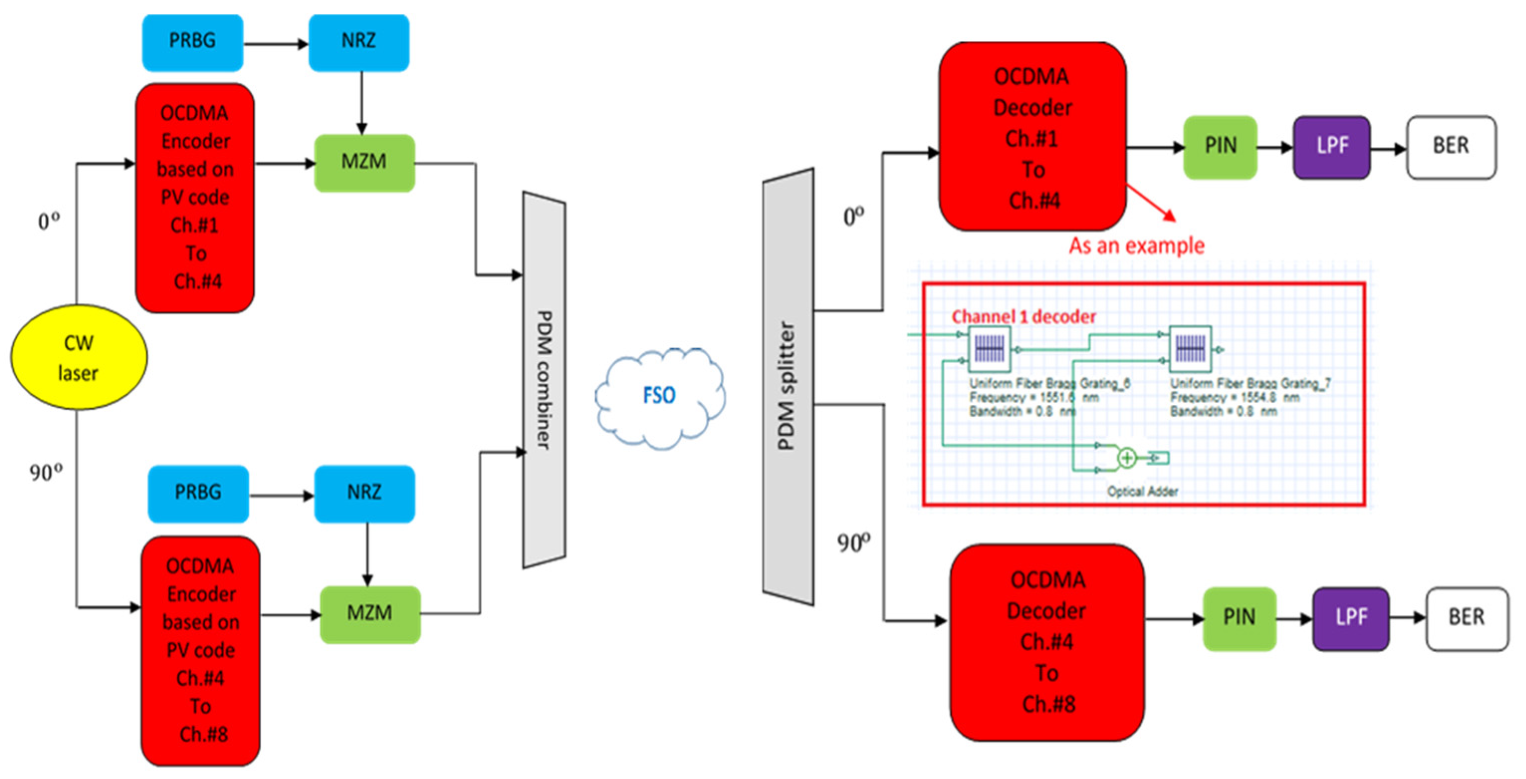
3. FSO-PDM/PV-OCDMA System Description

The schematic diagram of the proposed FSO-PDM/PV-OCDMA system is illustrated in Figure 1. Like any communication system, it consists of three parts (transmitter, channel, and receiver). At the transmitter, eight channels are assigned a PV code according to Table 1, and their wavelengths are generated from a continuous wave (CW) laser source. channels 1, 2, 3, and 4 are transmitted using x-polarization, which is delivered from a CW source at 0° azimuthal angle and the other channels (channels 5, 6, 7, and 8) are transmitted using y-polarization, which is delivered from a CW source at 90° azimuthal angle. Each of these channels carries 20 Gbps of information that is generated from a pseudo-random bit generator (PRBG) and a non-return to zero (NRZ) modulator. To modulate the information signal into the channels that are generated from optical signals coming from a CW source, a Mach–Zehnder modulator (MZM) is used. Further, the transmitters of the eight channels that come from different polarization signals (channels 1, 2, 3, and 4 on x-polarization and channels 5, 6, 7, and 8 on y-polarization) are combined through a PDM combiner, which further transmits to the FSO channel.
The signal during its transmission in the FSO channel is affected by various weather conditions such as clear air (CA), fog conditions (low fog, LF, medium fog, MF, and heavy fog, HF), dust storms (low dust storm, LD, medium dust storm, MD, and heavy dust storm, HD), and snow (wet snow, WS, and dry snow, DS). These weather conditions cause attenuation which degrades the signal strength during transmission between transmitter and receiver. CA weather condition has the least attenuation that is 0.14 dB/km [16]. While the attenuation under fog conditions differs according to the dense of the fog and it can be expressed as [21]
F = 3.912 D ( λ 550 n m ) p
where F , D and λ , respectively, are the fog attenuation in dB/km, the visibility in km, and the wavelength in nm while p is the size distribution of the scattering particle that can be determined according to the Kim model as [22]
p = { 1.6 D > 50 1.36 < D < 50 0.16 D + 0.341 < D < 6 D 0.50.5 < D < 1 0 D < 0.5
However, the large attenuation is caused under dust storms, which is expressed in dB/km as [23]
D = 52   ×   D 1.05
where D is the attenuation of the dust storm in dB/km. In the case of snow, the attenuation differs according to whether it is dry snow or wet snow, as dry snow refers to a low rate of snowfall while wet snow refers to a high rate of snowfall. The attenuation of snow, S , in dB/km can be expressed as [24]
S = a F b
where F is the rate of snowfall in mm/h. While a and b are parameters which in the case of dry snow and wet snow given as [24]
In   case   of   dry   snow ,   b = 1.38 ,   and   a = 5.42   ×   10 5 λ + 5.49 In   case   of   wet   snow ,   b = 0.72 ,   and   a = 1.02   ×   10 4 λ + 3.78
Finally, at the receiver, the received signal is divided by the PDM splitter into the two polarization signals (x and y polarizations) and the desired channel is detected by the decoder that has the same spectral as the encoder. The output signal then enters the photodiode (PD) detector for electrical/optical conversion which is further passed by a low-pass filter (LPF) for blocking the unwanted signals and a BER analyzer is used for checking the performance of the eight channels.

4. Performance Analysis

The received current of the desired channel at PD is expressed as [25]
I C h = R r P C W C L
where R indicates the responsivity of PD and r P is the received power which is given as [16]
r P = t P ( d r d t + Ø P r ) 2 10 α P r 10
where t P is the transmitted power, d t and d r , respectively are transmitter and receiver aperture diameters, Ø represents the beam divergence angle of the laser, and P r looks for propagation range. The signal-to-noise ratio, S/N, is [25]
S / N = ( I C h ) 2 σ S N + σ T h
where σ S N and σ T h , respectively are the powers of shot noise and thermal noise. σ S N is given as [25]
σ S N = 2 e B e l e c t r i c ( I C h )
where e and B e l e c t r i c are electron charge and electrical bandwidth, respectively.
While the thermal noise, σ T h , is given as [26]
σ T h = 4 k B T B e l e c t r i c R L
Here, k B is Boltzmann constant, R L and T are the load resistance of receiver and absolute temperature of receiver noise, respectively.
Therefore, the S/N will be
S / N = ( I C h ) 2 2 e B e l e c t r i c ( I C h ) + 4 k B T B e l e c t r i c R L
Finally, BER in terms of S/N will be [25]
B E R = 1 2 e r f c ( S / N 8 )
While BER in terms of Q-factor can be written as [27]
B E R = 1 2 e r f c ( Q 2 )

5. Simulation Results

The proposed FSO-PDM/PV-OCDMA system is evaluated and simulated using Matlab and Optisystem software version 18 with the parameters mentioned in Table 2 [27,28,29,30,31]. Optisystem is a commercial tool that offers designing, simulation, and optimization of optical components, links, systems, and networks. By using Optisystem software, the product time introduction to the market can be shortened and product quality can be improved.
In this section, the simulation results presented were obtained from simulating our suggested FSO-PDM/PV-OCDMA system. Effects of diverse weather conditions on our proposed system performance are discussed in terms of maximum FSO range, log (BER), Q-factors, and eye diagrams. The conducted results are divided according to different weather conditions into the following parts:

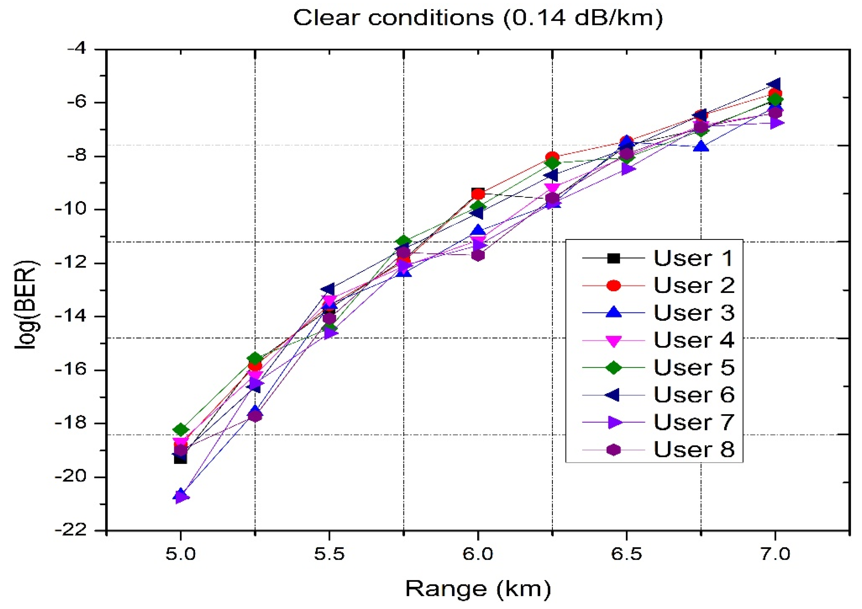
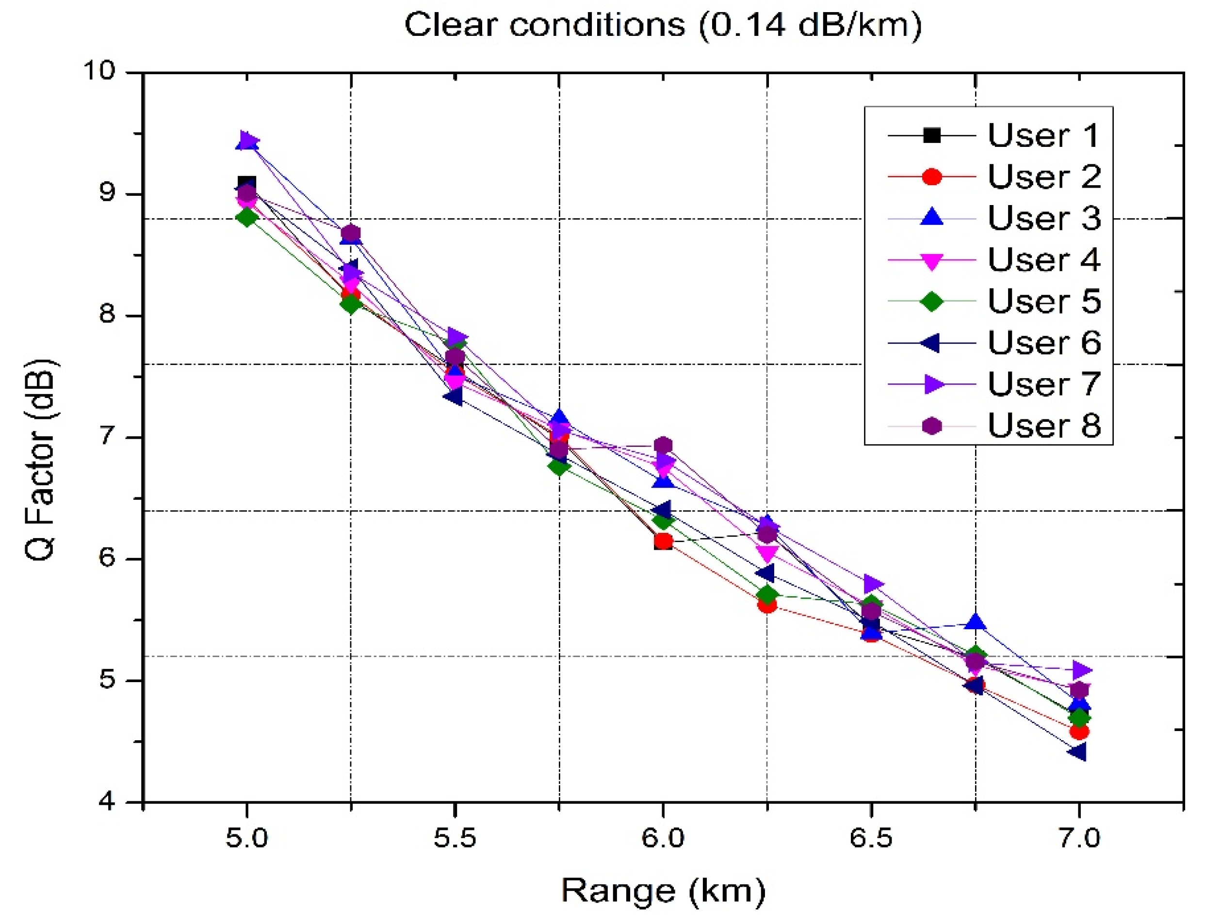
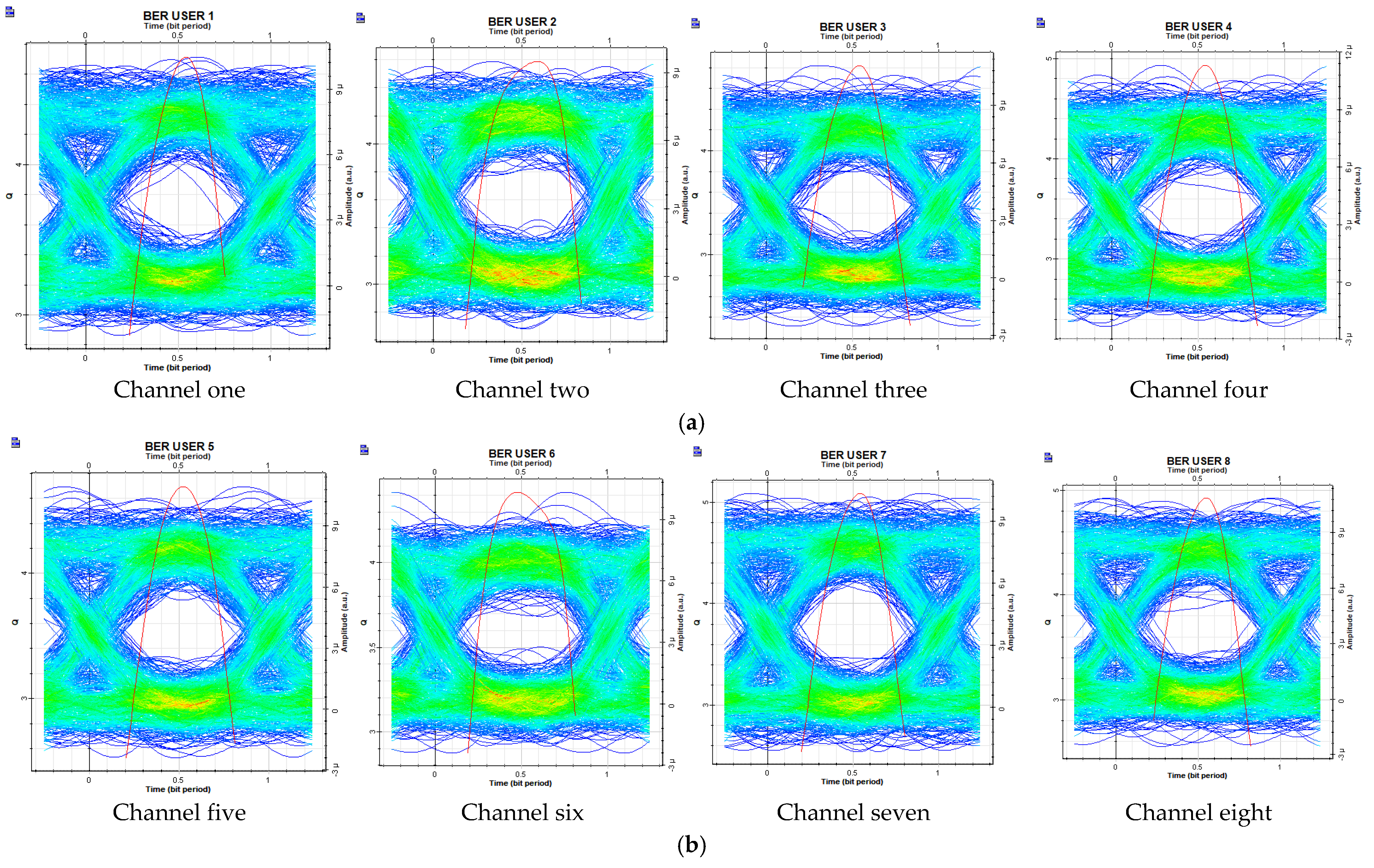
5.1. Effect of Clear Air on FSO-PDM/PV-OCDMA System

As clear air has less attenuation, that is 0.14 dB/km, this leads to less effect of the information signal during its propagation. It is seen from Figure 2 (log (BER) versus different FSO ranges) that the eight channels, which are transmitted using two polarization signals (four channels on x-polarization and four channels on y-polarization), can support up to 7 km FSO link with an overall capacity of 160 Gbps and log (BER) < −5. Table 3 shows the computed log (BER) for the eight channels at a 7 km propagation range.
Figure 3 depicts the Q-factor for channels 1, 2, 3, and 4 transmitted using x-polarization and channels 5, 6, 7, and 8 transmitted using y-polarization versus the propagation range for the proposed FSO-PDM/PV-OCDMA system. At a 7 km propagation range, the Q-factor values for channels 1 and 5, 2 and 6, 3 and 7, and 4 and 8, respectively, are 4.7 and 4.6, 4.5 and 4.4, 4.8 and 5, and 4.9 and 4.9, respectively.
Figure 4 displays the eye diagrams for the eight channels that propagate on two different polarization signals (X at 0 degrees and Y at 90 degrees) at a 7 km propagation distance. As all channels have a wide eye-opening, they advocate successful information transmission with an overall capacity of 160 Gbps.

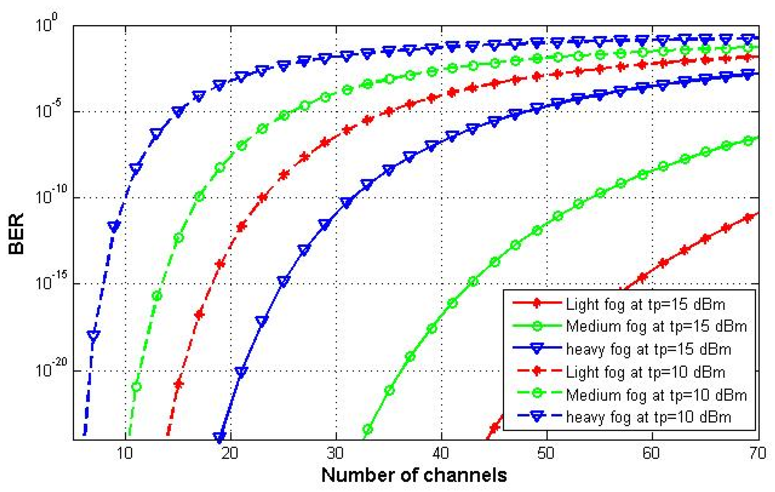
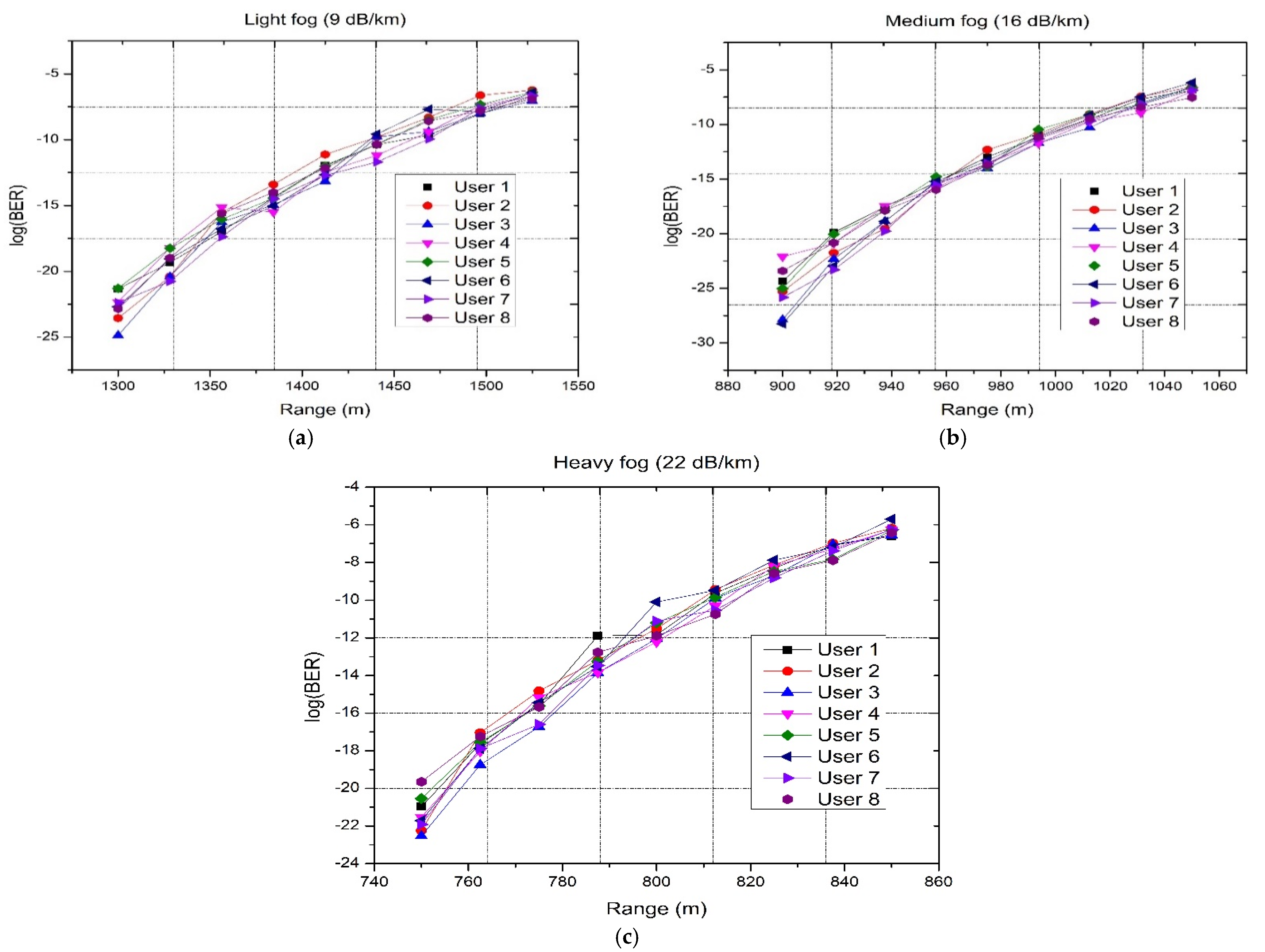
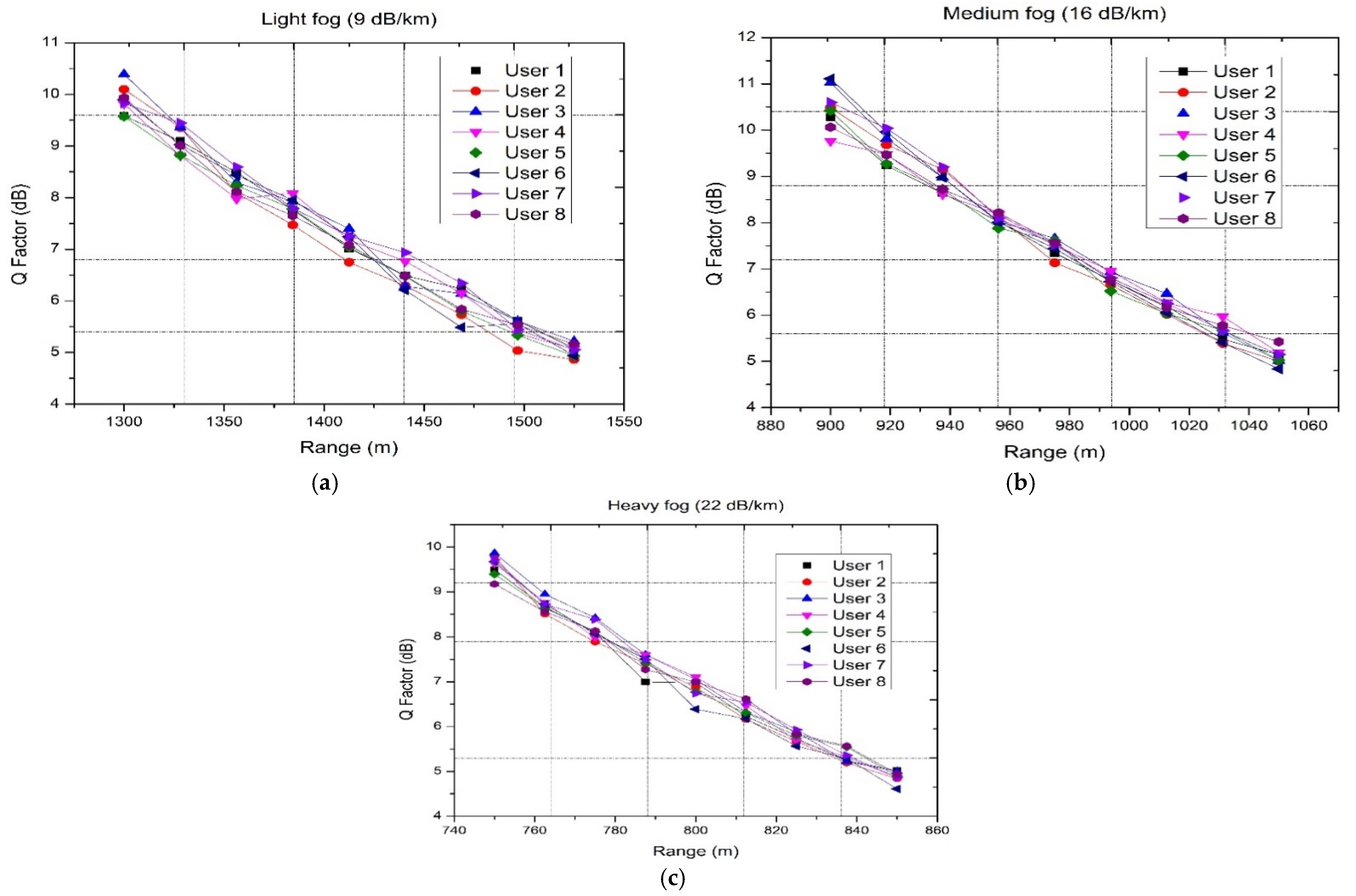
5.2. Effect of Fog Weather Conditions on FSO-PDM/PV-OCDMA System

The effects of different fog conditions (LF, MF, and HF) are discussed in this part.
Figure 5 shows the BER versus the number of channels that the proposed system can support at different transmission powers under foggy weather conditions and for different transmitted power at 20 Gbps. As the level of fog rises, the attenuation increases, and the allowable number of channels decreases. The LF has an attenuation of 9 dB/km, which is increased to 16 dB/km under MF and further increased to 22 dB/km under HF [15]. Furthermore, the number of channels at t p = 15 dBm is higher than that at t p = 10 dBm. At BER 10−9 and t p = 10 dBm, the maximum number of channels is 25, 19, and 10, respectively, under LF, MF, and HF. These channels increased when t p = 15 dBm is used to 83 under LF, 58 under MF, and 36 under HF at the same value of BER.
Figure 6 and Figure 7 depict the log (BER) versus the propagation range for the eight channels and Q-factor versus the propagation range for the eight channels, respectively. As the level of fog rises, the attenuation increases, the propagation range decreases, and the Q-factor decreases. Additionally, as the LF has less attenuation, our proposed system achieved the longest FSO range for the eight channels under its effect, which is 1.525 km. This range is slightly decreased to 1.05 km when the level of fog becomes medium, while at the heaviest level of fog, the shortest FSO link is achieved at 0.85 km and that is cleared as the largest attenuation is caused under HF. All these ranges are considered at acceptable BER values (less than 3 × 10⁻³).
Additionally, as the propagation range increases, the Q-factor decreases. Table 4 shows the computed log (BER) and the Q-factor for the eight channels at a propagation range of 1.525 km under LF, 1.05 km under MF, and 0.85 km under HF.

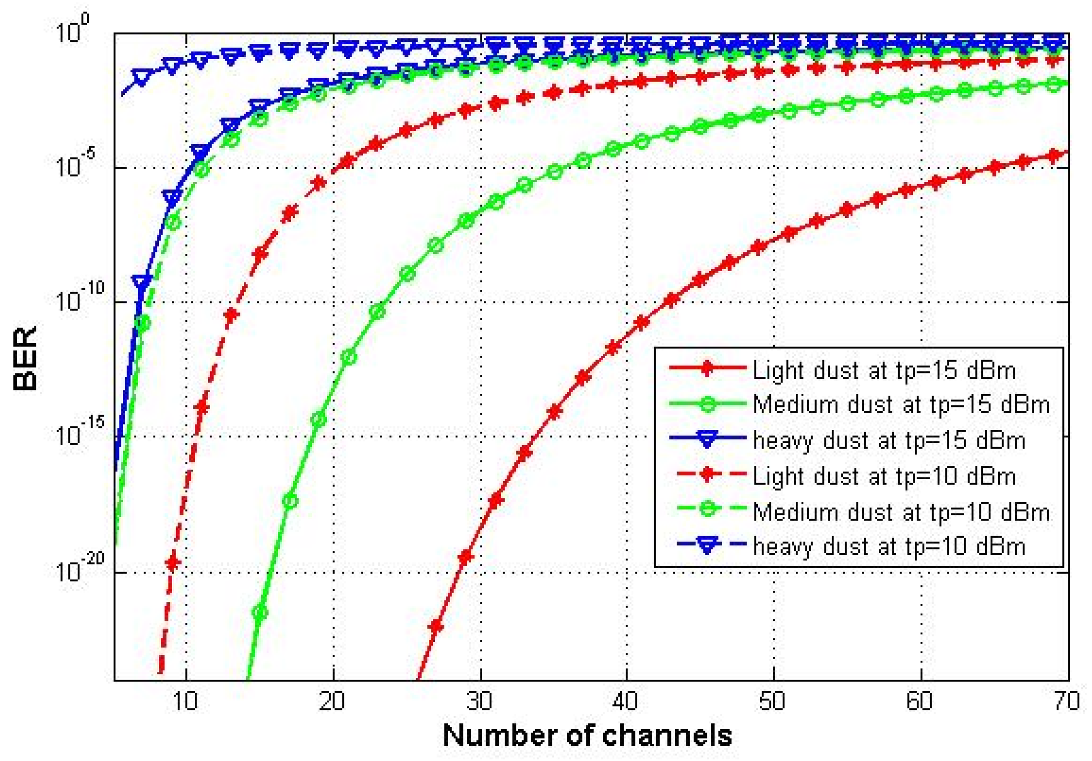
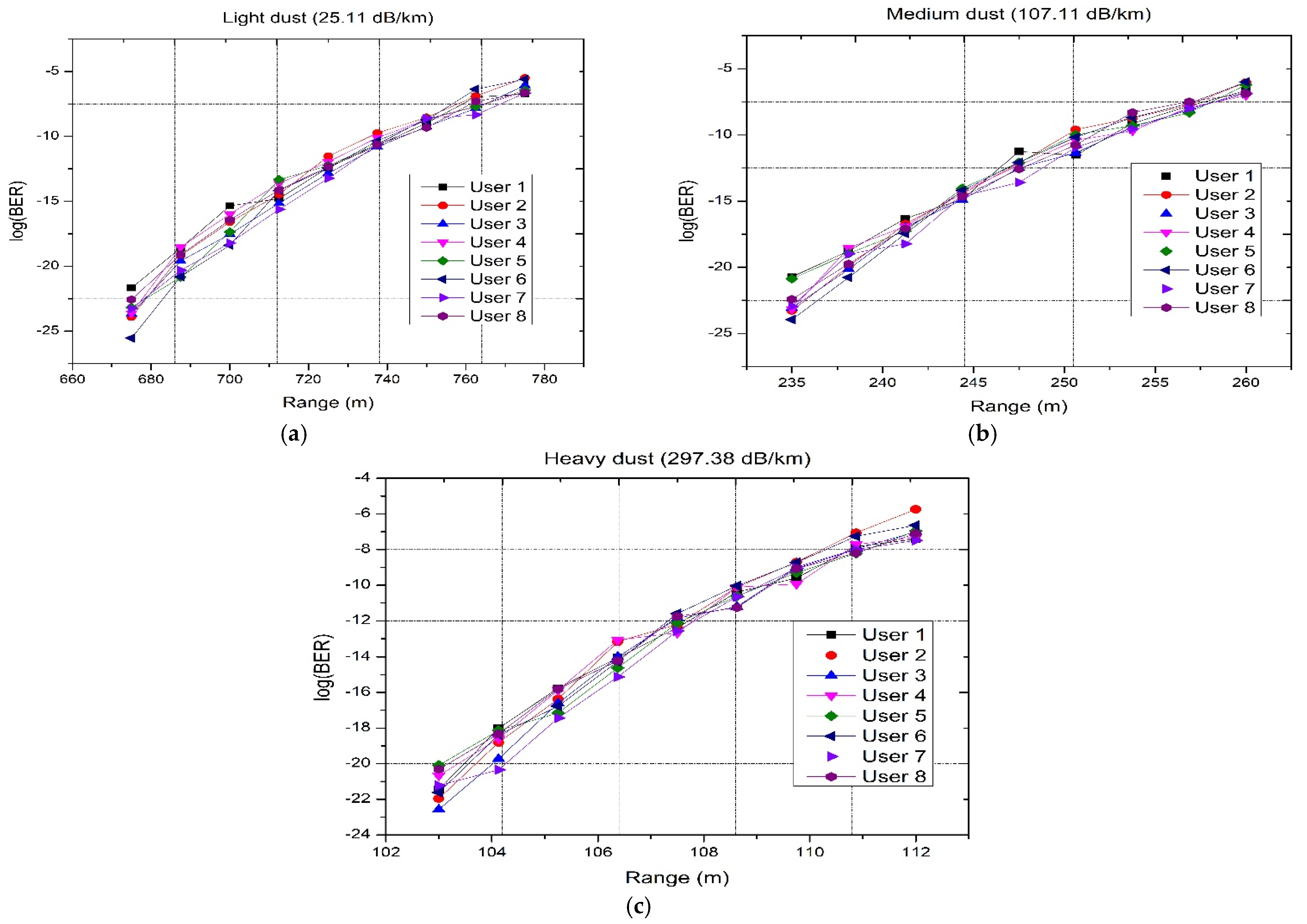
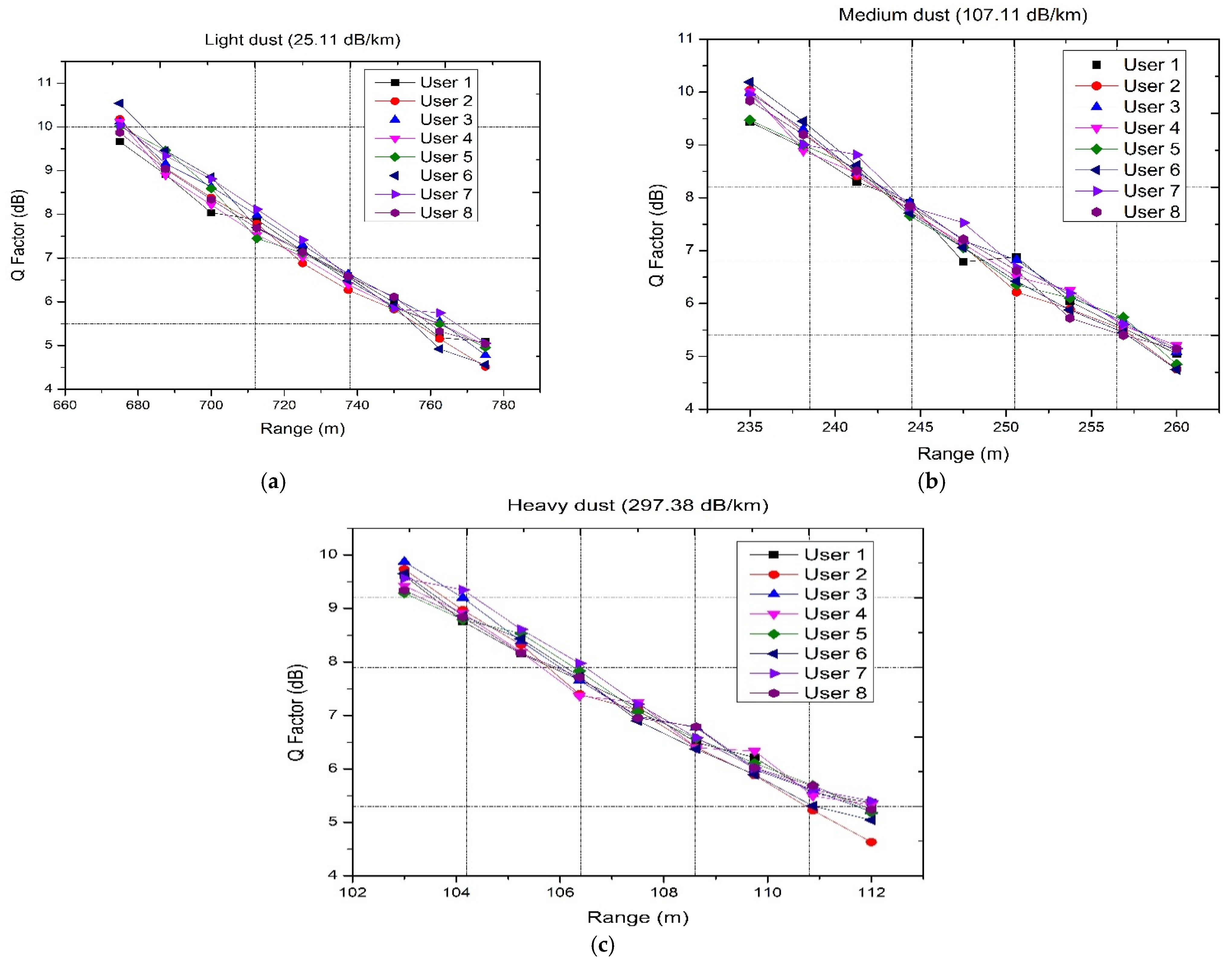
5.3. Effect of Dust Storms Conditions on FSO-PDM/PV-OCDMA System

The effect of different dust storms (LD, MD, and HD) on the performance of the proposed system is investigated in this part. The BER versus number of channels at 10 dBm and 15 dBm transmitted powers and 20 Gbps data rate under different dust storms is depicted in Figure 8. As the dust storm becomes heavier, the maximum number of allowable channels decreases. At LD, the number of channels that our proposed system can support is 47 at 15 dBm transmitted power and BER 10−9 which is decreased to 25 channels under MD and 8 channels under HD at same values of BER and t p . As for lower transmitted power, which is 10 dBm, one can observe that lower number of channels can be used (15 for LD, 9 for MD, and 3 for HD).
Figure 9 displays the log (BER) values under various dust storms versus the propagation distance for the eight simulated channels. Dust storms cause high attenuation to the information signal during propagation in the FSO channel, which leads to the shortest ranges compared to those achieved under fog conditions. The maximum transmission distance between the transmitter and the receiver under LD is 0.775 km, which decreases by 0.515 km under MD, and further decreases by 0.663 km under HD, which is seen in Figure 9a–c. This is expected as the attenuation value caused by dust storms is 25.11 dB/km, 107.11 dB/km, and 297.38 dB/km, respectively, under LD, MD, and HD, respectively [22].
Figure 10 shows the Q-factor for the eight channels of our suggested model under dust storms versus the FSO link. As propagation ranges increase, the Q-factor decreases as well under the different dust storms. The values of Q-factor at 0.775 km and under LD for the eight channels are 5.08, 4.51, 4.78, 5, 4.95, 4.56, 5.05, and 5.03, respectively. Approximately the same values of the Q-factor can be achieved at a 0.26 km propagation range under MD and a 0.112 km FSO link under HD. The computed log (BER) and the Q-factor for the eight channels at a propagation range of 0.775 km under LD, 0.26 km under MD, and 0.112 km under HD are given in Table 5.

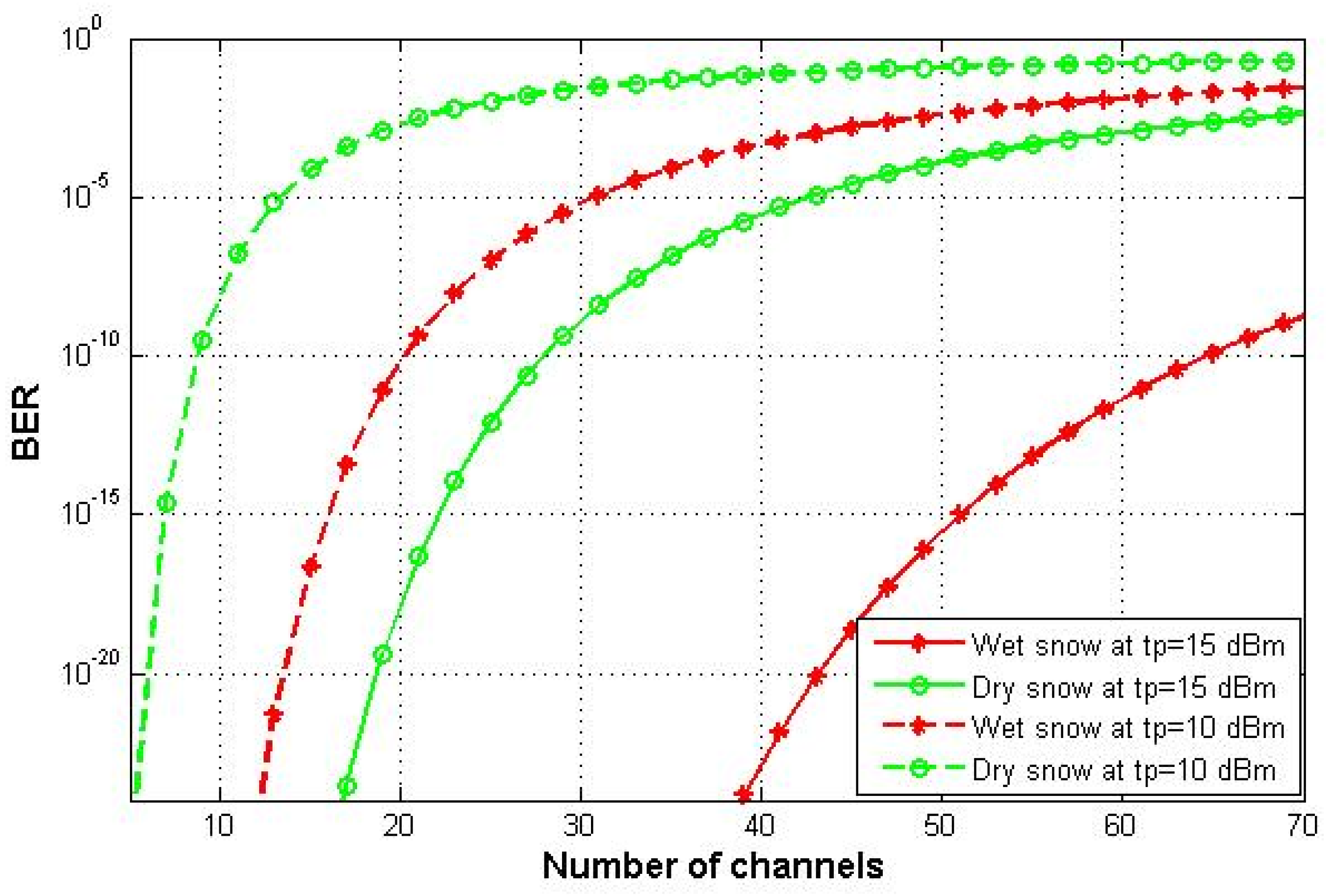
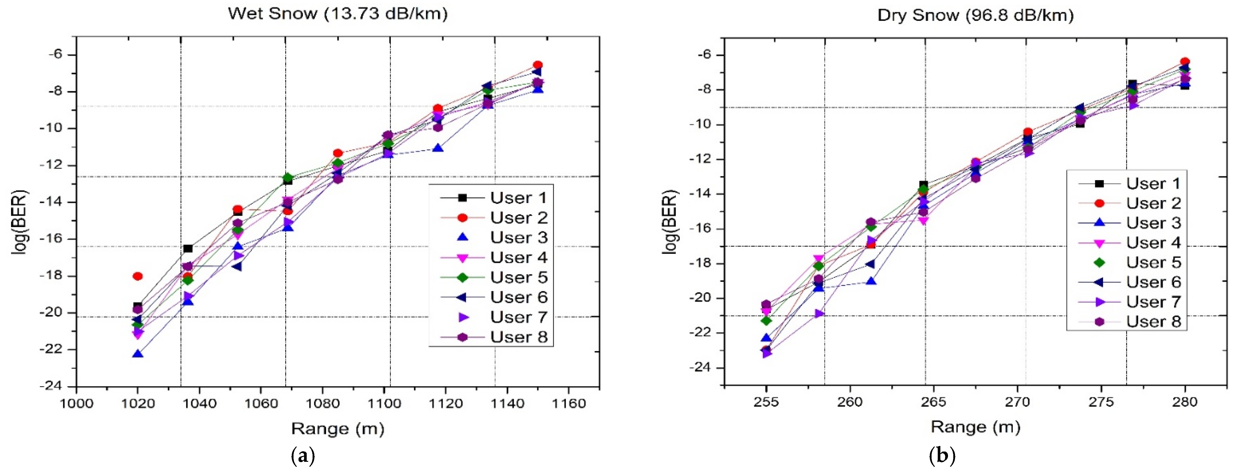
5.4. Effect of Wet and Dry Snow on FSO-PDM/PV-OCDMA System

Finally, the impact of dry and wet snow on the link performance is studied for all eight channels. The BER versus different number of channels that can be supported by the proposed system under WS and DS at different transmitted power and data rate of 20 Gbps is devoted in Figure 11. As cleared from Figure 11, the system under WS can support larger numbers of channels which are 70 and 21, respectively, at 15 dBm and 10 dBm transmitted power at BER 10−9. However, under DS, the proposed model can support lower numbers of channels, which are 30 at 15 dBm transmitted power and 9 at 10 dBm transmitted power.
Moreover, the system with eight channels carry information is simulated under different snowfall rates to show the effect of the propagation ranges on the information signal. From Figure 12 and Figure 13, the maximum FSO link for eight simulated channels is 1.15 km under WS, which causes attenuation (13.73 dB/km) less than that caused under DS (attenuation is 96.8 dB/km [31]). So, the FSO range for eight channels is decreased to 0.28 km under DS. These ranges are taken at acceptable BER values (less than 2.5 × 10⁻³) and Q-factor values approximately 5. The computed log (BER) and the Q-factor for the eight channels at a propagation range of 1.15 km under DS, and 0.28 km under WS are given in Table 6.
A comparison between our work and previously published works is given in Table 7.

6. Conclusions

A new 160 Gbps FSO communication is proposed by integrating PDM to OCDMA that uses PV code. Four different channels are used, each carries 20 Gbps, are transmitted on two orthogonal polarization states (x-polarization and y-polarization). Additionally, various weather conditions are considered to show the availability of applying the proposed system in different regions having different climates. These weathers are CA, fog (LF, MF, and HF), dust storms (LD, MD, and HD), and snowfall (WS and DS). Our proposed model is simulated under these weather conditions and the performance is carried out in terms of log (BER), Q-factor, and eye diagrams. The proposed model declares successful transmission of 160 Gbps with a maximum FSO range achieved under CA that is 7 km while the minimum is achieved under desert storms specific under HD and that is 0.112 km which is due to large attenuation caused by HD. Moreover, the FSO-PDM/PV-OCDMA system can transmit up to 1.525 km under LF. This range is slightly decreased to 1.05 km when the level of fog becomes medium, while at the heaviest level of fog, the shortest FSO link is achieved at 0.85 km and that is obvious as, under HF, the visibility is short while the attenuation is high. Further, as there are regions that have snow, we considered the performance of our suggested model under two types of snow that are WS and DS. Under WS, the system prolongs up to 1.15 km, while under DS, it prolongs up to 0.28 km. All these ranges are considered at the accepted value of BER (less than 2.5 × 10⁻³). Subsequently, the proposed FSO system can be implemented in 6G applications such as transmission of information between drones and buildings, vehicle-to-vehicle, hospitals, and hard-to-reach areas. In future works, practical experimentations of the proposed technique needs to be performed to better analyze the influence of real-time channel losses.

Author Contributions

Conceptualization, M.S. and S.A.A.E.-M.; methodology, M.S. and S.A.A.E.-M.; software, M.S. and S.A.A.E.-M.; validation, M.S., S.N.P. and S.A.A.E.-M.; formal analysis, M.S., S.N.P., A.A., K.A., M.A. and S.A.A.E.-M.; investigation, M.S. and S.A.A.E.-M.; resources, M.S. and S.A.A.E.-M.; writing—original draft preparation, M.S. and S.A.A.E.-M.; writing—review and editing, M.S. and S.A.A.E.-M.; visualization, M.S., S.N.P., A.A., K.A., M.A. and S.A.A.E.-M.; funding acquisition, A.A., K.A. and M.A. All authors have read and agreed to the published version of the manuscript.

Funding

This work was funded by the Deanship of Scientific Research at Jouf University under grant No (DSR2022-NF-13).

Institutional Review Board Statement

Not applicable.

Informed Consent Statement

Not applicable.

Conflicts of Interest

The authors declare no conflict of interest.

References

  1. Dat, P.T.; Kanno, A.; Yamamoto, N.; Kawanishi, T. Seamless Convergence of Fiber and Wireless Systems for 5G and Beyond Networks. J. Light. Technol. 2018, 37, 592–605. [Google Scholar] [CrossRef]
  2. Kanno, A.; Inagaki, K.; Morohashi, I.; Sakamoto, T.; Kuri, T.; Hosako, I.; Kawanishi, T.; Yoshida, Y.; Kitayama, K.-I. 40 Gb/s W-band (75–110 GHz) 16-QAM radio-over-fiber signal generation and its wireless transmission. Opt. Express 2011, 19, 56–63. [Google Scholar] [CrossRef]
  3. Pottoo, S.N.; Goyal, R.; Gupta, A. Performance investigation of optical communication system using FSO and OWC channel. In Proceedings of the 2020 Indo–Taiwan 2nd International Conference on Computing, Analytics and Networks (Indo-Taiwan ICAN), Rajpura, India, 7–15 February 2020; pp. 176–180. [Google Scholar]
  4. Tang, X.; Ghassemlooy, Z.; Rajbhandari, S.; Popoola, W.O.; Lee, C.G. Coherent Heterodyne Multilevel Polarization Shift Keying With Spatial Diversity in a Free-Space Optical Turbulence Channel. J. Light. Technol. 2012, 30, 2689–2695. [Google Scholar] [CrossRef]
  5. Karpagarajesh, G.; Krishnan, R.S.; Robinson, Y.H.; Vimal, S.; Kadry, S.; Nam, Y. Investigation of digital video broadcasting application employing the modulation formats like QAM and PSK using OWC, FSO, and LOS-FSO channels. Alex. Eng. J. 2022, 61, 647–657. [Google Scholar] [CrossRef]
  6. Sarangal, H.; Singh, A.; Malhotra, J.; Thapar, S.S. Performance Investigation of PM-ZCC Code in Hybrid SAC-OCDMA System through Inter-Satellite OWC Channel. Wirel. Pers. Commun. 2021, 120, 3329–3341. [Google Scholar] [CrossRef]
  7. Khalighi, M.A.; Uysal, M. Survey on Free Space Optical Communication: A Communication Theory Perspective. IEEE Commun. Surv. Tutor. 2014, 16, 2231–2258. [Google Scholar] [CrossRef]
  8. Pottoo, S.N.; Goyal, R.; Gupta, A. Development of 32-GBaud DP-QPSK free space optical transceiver using homodyne detection and advanced digital signal processing for future optical networks. Opt. Quantum Electron. 2020, 52, 496. [Google Scholar] [CrossRef]
  9. Chaudhary, S.; Choudhary, S.; Tang, X.; Wei, X. Empirical Evaluation of High-speed Cost-effective Ro-FSO System by Incorporating OCDMA-PDM Scheme under the Presence of Fog. J. Opt. Commun. 2020, 39, 1–4. [Google Scholar] [CrossRef]
  10. Esmail, M.A.; Fathallah, H.; Alouini, M. Effect of dust storms on FSO communications links. In Proceedings of the 2016 4th International Conference on Control Engineering & Information Technology (CEIT), Hammamet, Tunisia, 16–18 December 2016; pp. 1–6. [Google Scholar]
  11. Wang, Z.; Chowdhury, A.; Prucnal, P.R. Optical CDMA Code Wavelength Conversion Using PPLN to Improve Transmission Security. IEEE Photonics Technol. Lett. 2009, 21, 383–385. [Google Scholar] [CrossRef]
  12. El-Mottaleb, S.A.A.; Métwalli, A.; Hassib, M.; Alfikky, A.A.; Fayed, H.A.; Aly, M.H. SAC-OCDMA-FSO communication system under different weather conditions: Performance enhancement. Opt. Quantum Electron. 2021, 53, 616. [Google Scholar] [CrossRef]
  13. Palais, J.C. Fiber Optic Communications, 5th ed.; Pearson Prentice Hall: Upper Saddle River, NJ, USA, 2005. [Google Scholar]
  14. Singh, M.; Aly, M.H.; El-Mottaleb, S.A.A. Performance analysis of 6 × 10 Gbps PDM-SAC-OCDMA-based FSO transmission using EDW codes with SPD detection. Optik 2022, 264, 169415. [Google Scholar] [CrossRef]
  15. Ahmed, H.Y.; Zeghid, M.; Imtiaz, W.A.; Sharma, T.; Chehri, A. An efficient 2D encoding/decoding technique for optical communication system based on permutation vectors theory. Multimed. Syst. 2021, 27, 691–707. [Google Scholar] [CrossRef]
  16. Singh, M.; Atieh, A.; Aly, M.H.; El-Mottaleb, S.A.A. 120 Gbps SAC-OCDMA-OAM-based FSO transmission system: Performance evaluation under different weather conditions. Alex. Eng. J. 2022, 61, 10407–10418. [Google Scholar] [CrossRef]
  17. Chaudhary, S.; Amphawan, A.; Nisar, K. Realization of free space optics with OFDM under atmospheric turbulence. Optik 2014, 125, 5196–5198. [Google Scholar] [CrossRef]
  18. Rashidi, F.; He, J.; Chen, L. Spectrum slicing WDM for FSO communication systems under the heavy rain weather. Opt. Commun. 2017, 387, 296–302. [Google Scholar] [CrossRef]
  19. Zhou, X.; Huo, J.; Zhong, K.; Long, K.; Lü, C. Polarization division multiplexing system with direct decision for short reach optical communications. J. Beijing Univ. Posts Telecommun. 2017, 40, 21–28. [Google Scholar]
  20. Upadhyay, K.K.; Srivastava, S.; Shukla, N.K.; Chaudhary, S. High-Speed 120 Gbps AMI-WDM-PDM Free Space Optical Transmission System. J. Opt. Commun. 2019, 40, 429–433. [Google Scholar] [CrossRef]
  21. Chaudhary, S.; Sharma, A.; Tang, X.; Wei, X.; Sood, P. A Cost Effective 100 Gbps FSO System Under the Impact of Fog by Incorporating OCDMA-PDM Scheme. Wirel. Pers. Commun. 2020, 116, 2159–2168. [Google Scholar] [CrossRef]
  22. Kim, I.I.; McArthur, B.; Korevaar, E.J. Comparison of laser beam propagation at 785 nm and 1550 nm in fog and haze for optical wireless communications. In Proceedings of the Optical Wireless Communications III, Boston, MA, USA, 6–7 November 2000; SPIE: Bellingham, WA, USA, 2001; Volume 4214, pp. 26–37. [Google Scholar]
  23. Singh, M.; Atieh, A.; Grover, A.; Barukab, O. Performance analysis of 40 Gb/s free space optics transmission based on orbital angular momentum multiplexed beams. Alex. Eng. J. 2022, 61, 5203–5212. [Google Scholar] [CrossRef]
  24. Nadeem, F.; Leitgeb, E.; Awan, M.S.; Kandus, G. Comparing the Snow Effects on Hybrid Network Using Optical Wireless and GHz Links. In Proceeding of the 2009 International Workshop on Satellite and Space Communications, Tuscany, Italy, 9–11 September 2009; pp. 171–175. [Google Scholar]
  25. Moghaddasi, M.; Mamdoohi, G.; Noor, A.S.M.; Mahdi, M.A.; Anas, S.B.A. Development of SAC–OCDMA in FSO with multi-wavelength laser source. Opt. Commun. 2015, 356, 282–289. [Google Scholar] [CrossRef]
  26. Anuar, M.; AlJunid, S.; Arief, A.; Junita, M.; Saad, N. PIN versus Avalanche photodiode gain optimization in zero cross correlation optical code division multiple access system. Optik 2013, 124, 371–375. [Google Scholar] [CrossRef]
  27. Ahmed, H.Y.; Zeghid, M.; Bouallegue, B.; Chehri, A.; El-Mottaleb, S.A.A. Reduction of Complexity Design of SAC OCDMA Systems by Utilizing Diagonal Permutation Shift (DPS) Codes with Single Photodiode (SPD) Detection Technique. Electronics 2022, 11, 1224. [Google Scholar] [CrossRef]
  28. Al-Khafaji, H.M.R.; Aljunid, S.A.; Amphawan, A.; Fadhil, H.A.; Safar, A.M. Reducing BER of spectral-amplitude coding optical code-division multiple-access systems by single photodiode detection technique. J. Eur. Opt. Soc. Publ. 2013, 8, 13022. [Google Scholar] [CrossRef] [Green Version]
  29. Kakati, D.; Arya, S.C. Performance of 120 Gbps single channel coherent DP-16-QAM in terrestrial FSO link under different weather conditions. Optik 2019, 178, 1230–1239. [Google Scholar] [CrossRef]
  30. Zhang, C.; Liang, P.; Nebhen, J.; Chaudhary, S.; Sharma, A.; Malhotra, J.; Sharma, B. Performance analysis of mode division multiplexing-based free space optical systems for healthcare infrastructure’s. Opt. Quantum Electron. 2021, 53, 635. [Google Scholar] [CrossRef]
  31. Salamah, S.; Alsubaie, M.A.; Alhajri, M.; Alnaser, M.; Abdalla, A.M. The Effects of Power Control on Free-Space Optical Communications during Snowfall and Rainfall. Int. J. Commun. Netw. Syst. Sci. 2018, 11, 216–227. [Google Scholar] [CrossRef]
Figure 1. Schematic diagram of FSO-PDM/PV-OCDMA system.
Applsci 12 11374 g001
Figure 2. Log (BER) of FSO-PDM/PV-OCDMA system versus FSO link under clear air weather.
Applsci 12 11374 g002
Figure 3. Q-factor of FSO-PDM/PV-OCDMA system versus FSO link under clear air weather.
Applsci 12 11374 g003
Figure 4. Eye diagrams for eight channels of the FSO-PDM/PV-OCDMA system transmitted on (a) x-polarization and (b) y-polarization.
Applsci 12 11374 g004
Figure 5. BER of FSO-PDM/PV-OCDMA system versus number of channels under foggy conditions.
Applsci 12 11374 g005
Figure 6. Log (BER) of FSO-PDM/PV-OCDMA system versus FSO link under (a) LF, (b) MF, and (c) HF.
Applsci 12 11374 g006
Figure 7. Q-factor of FSO-PDM/PV-OCDMA system versus FSO link under (a) LF, (b) MF, and (c) HF.
Applsci 12 11374 g007
Figure 8. BER of FSO-PDM/PV-OCDMA system versus number of channels under dusty conditions.
Applsci 12 11374 g008
Figure 9. log (BER) of FSO-PDM/PV-OCDMA system versus FSO link under (a) LD, (b) MD, and (c) HD.
Applsci 12 11374 g009
Figure 10. Q-factor of FSO-PDM/PV-OCDMA system versus FSO link under (a) LD, (b) MD, and (c) HD.
Applsci 12 11374 g010
Figure 11. BER of FSO-PDM/PV-OCDMA system versus number of channels under snowy conditions.
Applsci 12 11374 g011
Figure 12. Log (BER) of FSO-PDM/PV-OCDMA system versus FSO link under (a) DS, and (b) WS.
Applsci 12 11374 g012
Figure 13. Q-factor of FSO-PDM/PV-OCDMA system versus FSO link under (a) DS, and (b) WS.
Applsci 12 11374 g013
Table 1. Channels with their corresponding wavelengths.
Channels/Wavelengths15501550.81551.61552.41553.215541554.81555.6
Channels 1, 400 λ 3 000 λ 7 0
Channels 2, 50000 λ 5 λ 6 00
Channels 3, 60 λ 2 00000 λ 8
Channels 4, 8 λ 1 00 λ 4 0000
Table 2. Simulation parameters [27,28,29,30,31].
Symbol/ParameterValue
t P (dBm): CW laser source input power15
Laser linewidth10 MHz
R b (Gbps): bit rate per channel20
Number of channels8
B e l e c t r i c (Hz): electrical bandwidth0.75 × Bit rate
Divergence angle1 mrad
d r (cm): receiver aperture diameter10
d t (cm): transmitter aperture diameter20
R (A/W): PD responsivity1
Thermal noise power density 10 22 W/Hz
T (K): receiver noise temperature300
R L : receiver load resistance 1030   Ω
Table 3. log (BER) values of eight channels of FSO-PDM/PV-OCDMA system at 7 km.
Channels12345678
Polarization signalx-polarizationy-polarization
Log (BER)−5.91−5.64−6.14−6.39−5.87−5.3−6.74−6.38
Table 4. log (BER) values and Q-factors of eight channels of FSO-PDM/PV-OCDMA system under different fog conditions and propagation ranges.
Channels12345678
Polarization signalx-polarizationy-polarization
Log (BER)under LF (1.525 km)−6.7−6.23−7−6.7−6.39−6.41−6.66−6.91
Q-factor5.074.865.215.074.934.945.055.16
Log (BER)under MF (1.05 km)−6.87−6.55−6.57−6.98−6.61−6.18−6.87−7.54
Q-factor5.1455.015.195.034.835.145.42
Log (BER)under HF (0.85 km)−6.59−6.18−6.55−6.25−6.29−5.7−6.25−6.42
Q-factor5.024.8354.864.884.614.864.94
Table 5. log (BER) values and Q-factors of eight channels of FSO-PDM/PV-OCDMA system under dust storm conditions and propagation ranges.
Channels12345678
Polarization signalx-polarizationy-polarization
Log (BER)under LD (0.775 km)−6.74−5.49−6.06−6.56−6.44−5.59−6.66−6.62
Q-factor5.084.514.7854.954.565.055.03
Log (BER)under MD (0.26 km)−6.65−6−6.73−7.02−6.21−5.99−6.88−6.87
Q-factor5.044.755.085.24.847.755.145.14
Log (BER)under HD (0.112 km)−7.4−5.74−7−7.31−6.95−6.63−7.48−7.1
Q-factor5.364.625.195.325.185.045.45.24
Table 6. Log (BER) values and Q-factors of eight channels of FSO-PDM/PV-OCDMA system under different snowfall and propagation ranges.
Channels12345678
Polarization signalx-polarizationy-polarization
Log (BER)under WS (1.15 km)−7.59−6.54−7.9−7.46−7.47−6.91−7.49−7.48
Q-factor5.444.995.575.395.45.165.45.4
Log (BER)under DS (0.28 km)−7.76−6.35−7.61−7.11−6.79−6.7−7.32−7.36
Q-factor5.514.915.455.245.115.075.335.35
Table 7. Comparison between present work and previous recent works.
ReferenceThe Technique Used in FSO SystemNumber of ChannelsOverall CapacityWeather Conditions
[17]OFDM110 GbpsCA
[16]OAM-OCDMA using EDW code12120 GbpsCA, fog, haze, and rain
[14]PDM-OCDMA using EDW code660 GbpsCA, fog, haze, and rain
[21]PDM-OCDMA using RD code10100 GbpsFog
Present workPDM-OCDMA using PV code8160 GbpsCA, fog, dust storms, snowfall
Publisher’s Note: MDPI stays neutral with regard to jurisdictional claims in published maps and institutional affiliations.

