


Systematic Approach for Alignment of Light Field Mirage
by
Yoshiharu Momonoi
1,2,*,
Koya Yamamoto
2,
Yoshihiro Yokote
1,
Atsushi Sato
1 and
Yasuhiro Takaki
2 1
SRJ-Y, Samsung R&D Institute Japan, 2-7, Sugasawa-cho, Tsurumi-ku, Yokohama 230-0027, Japan
2
Institute of Engineering, Tokyo University of Agriculture and Technology, 2-24-16 Naka-cho, Koganei 184-8588, Japan
*
Author to whom correspondence should be addressed.
Appl. Sci. 2022, 12(23), 12413; https://0-doi-org.brum.beds.ac.uk/10.3390/app122312413
Submission received: 26 October 2022
/
Revised: 24 November 2022
/
Accepted: 28 November 2022
/
Published: 4 December 2022
(This article belongs to the Special Issue Holography, 3D Imaging and 3D Display Volume II)
Abstract
:We previously proposed techniques to eliminate repeated three-dimensional (3D) images produced by the light field Mirage, which consists of circularly aligned multiple-slanted light field displays. However, we only constructed the lower half of the system to verify the proposed elimination techniques. In this study, we developed an alignment technique for a complete 360-degree display system. The alignment techniques for conventional 360-degree display systems, which use a large number of projectors, greatly depend on electronic calibration, which indispensably causes image quality degradation. We propose a systematic approach for the alignment for the light field Mirage, which causes less image quality degradation by taking advantage of the small number of display devices required for the light field Mirage. The calibration technique for light field displays, the image stitching technique, and the brightness matching technique are consecutively performed, and the generation of 360-degree 3D images is verified.
1. Introduction
Observing 360-degree three-dimensional (3D) display systems can be used for digital signage, medical demonstrations, and Internet shopping. We previously proposed techniques to eliminate repeated 3D images produced by the light field Mirage, which produces 360-degree 3D images to simulate the conventional Mirage [1]. However, we only constructed a part of the system to verify the elimination techniques. Thus, the previous system could not achieve 360-degree visibility. In this study, we develop a technology that connects multiple light field displays (LFDs) to complete the 360-degree visibility, which includes calibration for LFDs, stitching of images in overlapped LFDs, and matching of LFDs’ brightness.
Various techniques of 360-degree 3D displays have been proposed. Early displays used 3D glasses [2], in which a hole was used to distribute different 3D images to different viewers. Subsequent glasses-free 360-degree 3D displays used time-multiplexing systems, which adopted a combination of 1D LED arrays and a rotating mechanism [3,4] or a high-speed projector and circular scanning system [5,6,7,8,9]. Multi-projection systems [10,11,12,13,14,15,16] and flat-panel systems [17,18] have since been developed for glasses-free 360-degree 3D displays. The former systems project on to a screen from a large number of videos projectors. The latter systems consist of a high-resolution flat-panel display and specially designed lenses.
For multi-projection systems, alignment techniques are essential as they consist of a large number of projectors, i.e., between 64 and 288 [10,11,12,13,14,15,16]. Mechanical adjustments require laborious work and are impractical for aligning them; therefore, multi-projection systems greatly rely on electronic calibration, which ultimately causes image quality degradation. The correction and distortion of images reduce its effective resolution. Mechanical adjustment among multiple display devices is preferable because the image quality is not reduced. Although an alignment technique is also required for the light field Mirage [19], its number of display devices is much smaller than for multi-projection systems.
Flat-panel systems require a specially designed lens array, which consists of triplet lenses or aspheric conical lenses used to reduce the aberration, to distribute rays in 360-degree directions from the lens array [17,18]. The aspheric conical lens array is designed to distribute the light rays emitting from the elemental images with a ring-type distribution instead of a uniform distribution [18]. A large number, such as 1196 pieces of aspheric conical lens are required to be molded and assembled, which is expensive and requires complex assembly. To prevent using specially designed lens arrays, the light field Mirage used multiple slanted LFDs aligned in a circular manner to emit rays in 360-degree directions. This enables commercially available lens arrays to be used. The adjustment of a lens array and flat-panel display for each LFD is required.
In this study, we aim to develop an effective alignment technique to combine multiple LFDs. Because the system utilizes a limited number of LFDs with normal lens arrays, we prioritize mechanical adjustment over electronic adjustment, i.e., the image calibration, to minimize image degradation. Thus, we developed a systematic approach for the alignment of the light field Mirage as three steps, i.e., (1) calibration for LFDs, (2) stitching of images, and (3) matching of image brightness.
2. Light Field Mirage
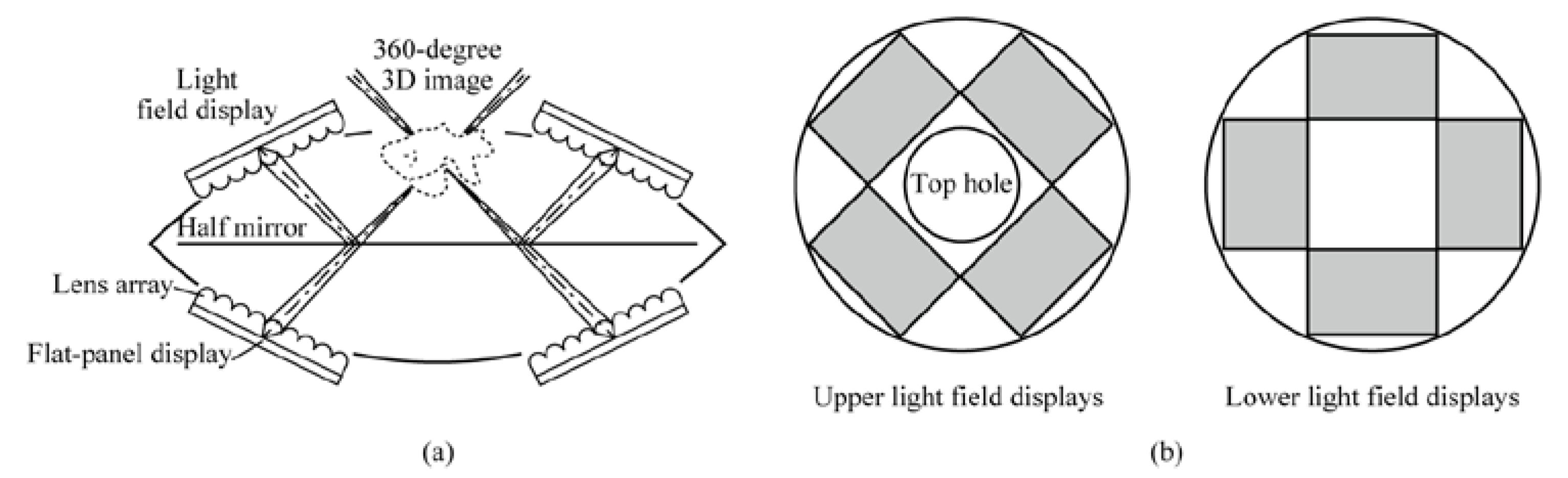
First, we briefly explain the light field Mirage that was proposed in our previous study [1]. We previously proposed a concept of a digital implementation system in which LFDs, which substitute the existing Mirage parabolic mirrors, generate a 360-degree 3D image in the top hole as shown in Figure 1. The LFDs are alternately configured between upper and lower positions, and the optical distance from the upper LFDs to the top hole is the same as that from the lower LFDs by using a half mirror. The LFDs not only generated an aerial 3D image at the top hole leveraged by the resolution-priority technique [20,21], but also provided higher-resolution 3D images than the conventional depth-priority technique [22]. The plane at the top hole where the aerial images are produced is called the “central depth plane” (CDP) in the resolution-priority technique. The lens array of LFDs uses an ordinary lens array, since slanted LFDs are circularly aligned to redirect rays across the whole circumference. The number of display devices for the light field Mirage were significantly less than that of multi-projection systems [10,11,12,13,14,15,16] to utilize LFDs. In addition, as the light field Mirage consists of multiple LFDs, flat-panel displays for LFDs enable the use of middle-resolution displays in contrast to conventional flat-panel systems.
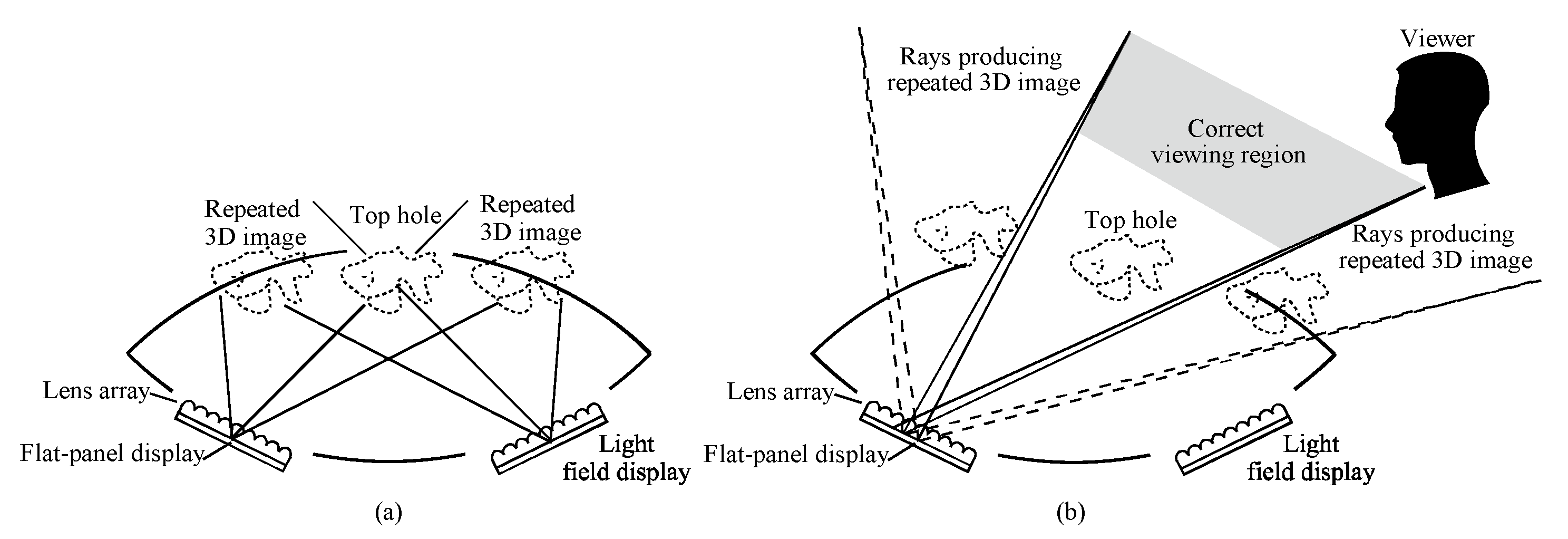
Because flat-panel type LFDs generate repeated 3D images, we have developed two techniques to avoid the observation of repeated 3D images by viewers. The first technique, “non-tracking”, eliminates repeated 3D images by using the top hole, since desired 3D images from all LFDs are overlaid on one another in the CDP, as shown in Figure 2a. The second technique, “tracking”, divides the rays from the desired 3D image on the viewing plane. Therefore, repeated 3D images can be bypassed by moving the correct viewing regions, as shown in Figure 2b. Although the first technique does not require tracking of viewers, the 3D image size was constrained, and even though the second technique requires tracking of viewers, large 3D image sizes could be produced.
When the LFD width is denoted by wd, the radius from the central axis of the display system to the center of each screen placed on the circumference is denoted by r, because the angle of view for the LFD width from the center, denoted by φ, is given by φ = 2 tan−1(wd/2r), and the number of LFDs required to assemble the system, denoted by N, is given by:
When the distance from the lens array to the CDP is denoted by li, the inclination angle is given by α = sin−1 (r/li).
For the non-tracking technique, the lens pitch of the lens array is denoted by pl, and the number of the rays for one LFD is denoted Nr and is equal to the number of lenses in the array as Nr = wd/pl. The pixel pitch of the flat-panel displays is denoted by pp, and the 3D image resolution along the diameter of the top hole, denoted by X3D, is equal to the number of elementary images:
For the tracking technique, the number of rays for one LFD is equal to the resolution of the elementary images by Nr = pl/pp. The pixel number of the flat-panel displays is represented by X × Y, and the 3D image height relates to the flat-panel display height. Taking into account the inclined screen, the 3D image height is given by:
For the resolution-priority technique, the focal length of the lens array is denoted by f, that between the lens array and the pixels of the flat-panel display is denoted by lo, and the 3D image pixel pitch is given by pp li/lo ≃ pp li/f. The 3D resolution is given by:
3. Design of Complete Light Field Mirage
Prior to the development of the alignment techniques, we completed the design of the full light field Mirage. We provided the same LFDs as those used in our previous study [19]. We constructed each LFD by using 6-inch liquid-crystal displays (LCDs) (Sharp, LS060R1SX01), which have a resolution of 2560 × 1440. The lens arrays configured for the LFD were hexagonal lens arrays with a focal length of 10.0 mm and lens pitch of 1.98 mm. The size of the lens arrays was 100.0 × 74.0 mm2. The distance from the centers of the LFD screens to the center of the top hole was 119 mm, which was equal to the distance from the CDP. The length between the lens array and LCD screens was 10.7 mm. All of the LFDs were inclined at an angle of 45.0°.
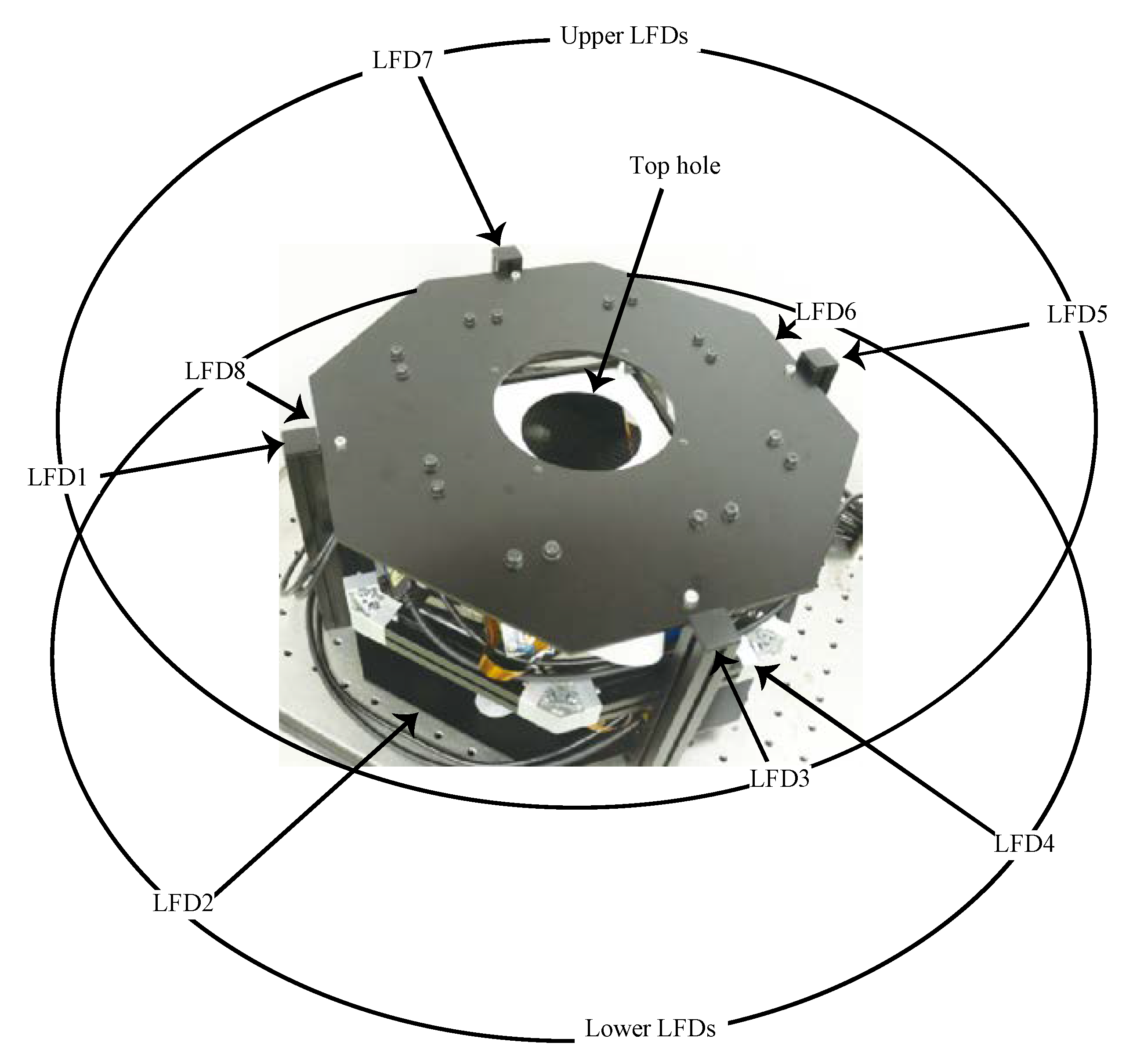
From Equation (1), the minimum number of LFDs is N = 5.9. Constructing the experimental system required the use of eight LFDs due to the increased number required to assemble a symmetric shape; four LFDs for the upper and lower parts, respectively. A photograph of the constructed experimental system is shown in Figure 3.
Rays from the lower displays are transmitted through a half mirror, and those from the upper displays are reflected by the half mirror to the top hole. Although the light absorption of the metallic half mirrors is higher than that of dielectric half mirrors, we used a metallic half mirror because a large dielectric half mirror requires a high cost and has strict restrictions on wavelengths and incident angles. The dimensions of the constructed experimental system were approximately 330 (W) × 330 (D) × 180 (H) mm3. For the non-tracking technique, the diameter of the top hole was 24.2 mm, and the resolution of the 3D images observed through the top hole was 41.7 pixels along the hole’s diameter. The viewing distance used in the design as the distance from a viewer to the LFD screen was 600 mm. For the tracking technique, the diameter of the top hole was 78.0 mm, which was the apparent width of the screens of the LFDs observed at the viewing distance, and the resolution of the 3D images observed through the top hole was 172 × 127.
4. Calibration Technique for LFDs
Because the light field Mirage consists of a small number of LFDs, this study developed a calibration strategy suitable for it. First, each LFD is calibrated mechanically. Then, the alignment of multiple LFDs is calibrated mechanically. Finally, electronic calibration is performed to finely adjust the 3D images generated by the multiple LFDs.
In the first step, each LFD was calibrated individually so that the uniformity of all LFDs was ensured. The lateral and transverse positions of the lens array should be mechanically aligned against the LCD. The longitudinal position of the lens array was made equivalent for all LFDs using acrylic plates, which were sandwiched between the lens arrays and LCDs. Two kinds of acrylic plates with thicknesses of 15.00 and 0.65 mm were attached to precisely maintain the longitudinal position. The transverse position of the lens array was made equivalent for all LFDs using a camera located in front of the LFD. The camera was positioned so that its optical axis passed through the center of the lens array, and the distance between the camera and lens array was set as the viewing distance. For all lenses in the lens array, one pixel in all elementary images that emitted rays passing through the camera position was calculated. Then, only the determined pixels were made to emit light. The lens array was slid on the acrylic spacers so that the camera observed light from all lenses.
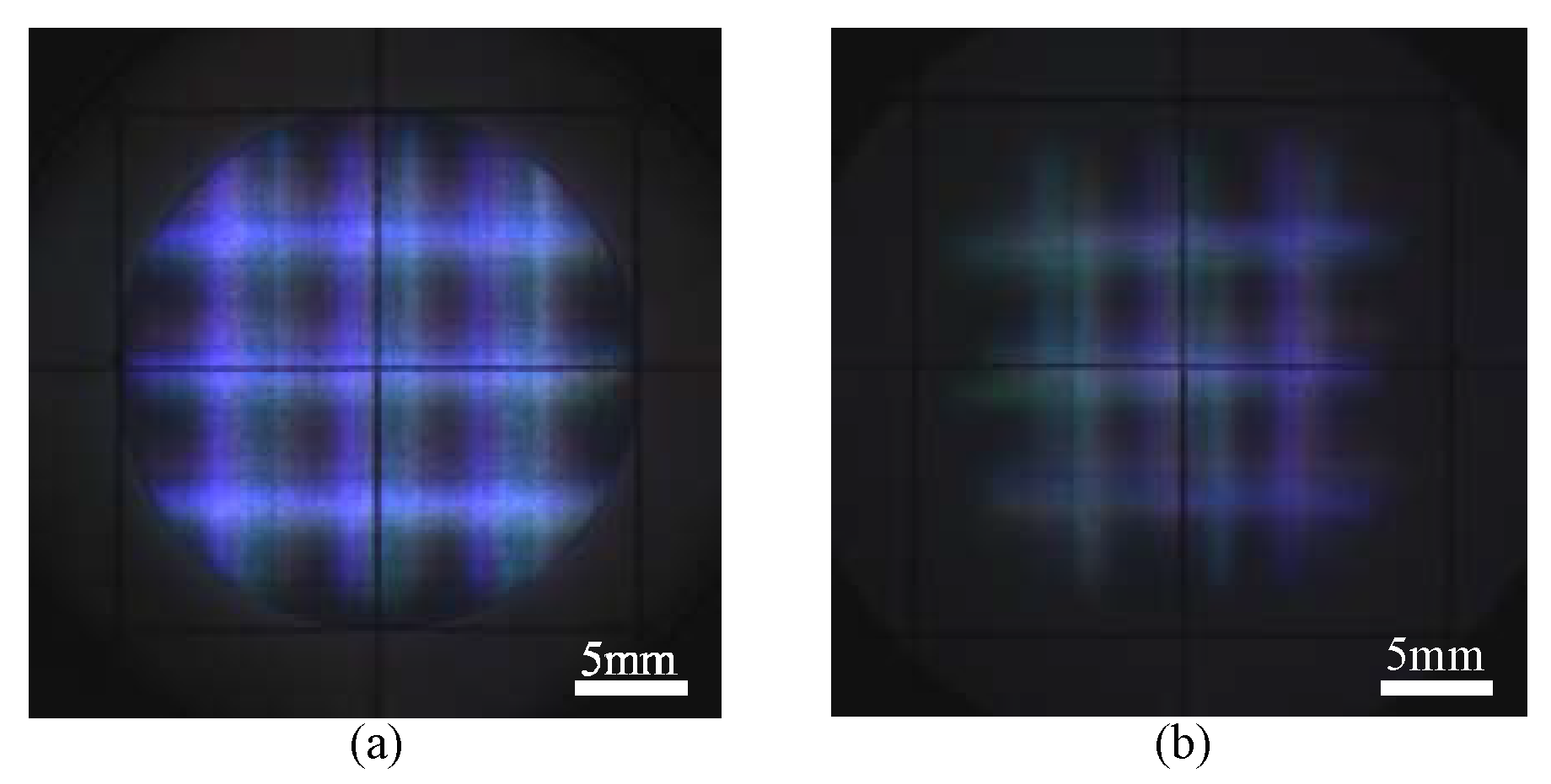
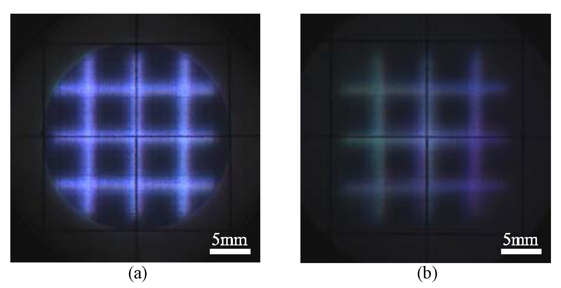
In the second step, the positions of the eight LFDs were adjusted. The LFDs were attached to the upper and lower aluminum plates using off-the-shelf 45-degree angle brackets. A sheet of tracing paper was placed at the top hole of the light field Mirage and each LFD displayed a grid pattern at the top hole position (the CDP position). The positions of the LFDs were moved along the aluminum plates so that all grid patterns were superimposed on one another. The grid pattern used a different color for each LFD to easily identify the shifted LFD. The resultant superimposed image is shown in Figure 4a. As shown in this figure, it was impossible to superimpose all grid patterns at the same position, because of the residual non-uniformity among the eight LFDs after the first step. Then, the tracing paper was moved upward over a distance of 14 mm, and all the LFDs displayed the grid patterns at the same position at this height. Figure 4b shows the superimposition of the grid patterns. The mismatch of the grid pattern positions became larger compared with that shown in Figure 4a. Therefore, adjustment to the ray directions among the LFDs was required.
In the last step, the electronic calibration was conducted for the adjustment of the ray directions. The positions of the elementary images, as well as the pitches of the elementary images displayed on the LCDs, were manually adjusted so that all grid patterns were superimposed on one another. The adjustments were conducted using the tracing paper positioned at the top hole. The maximum shift of the elementary images among the eight displays was three pixels. From the resultant image shown in Figure 5a, the superposition of the grid patterns improved. Then, the tracing paper was moved, as explained in the second step, and the obtained image is shown in Figure 5b. The result shown in Figure 5b was colored because a part of the displays was hindered by the top hole, but the coincidence of the grid patterns was as good as that shown in Figure 5a. Therefore, the ray directions of all the LFDs were well-calibrated.
5. Image Stitching Technique for Multiple Skewed LFDs
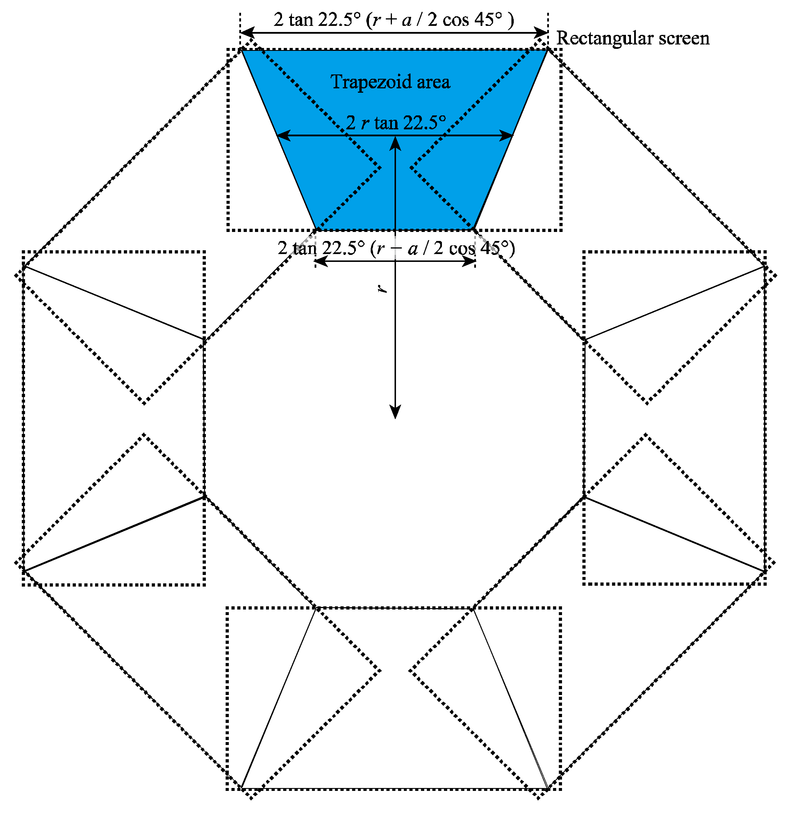
The light field Mirage approximates the parabolic mirror surfaces of the original Mirage as multiple LFDs to provide a continuous 360-degree viewing zone. As shown in Figure 6, because the LFDs have flat rectangular screens, there exists overlapping regions among the screens of the LFDs. The overlapping regions become visible because their intensities become higher than those of the surroundings. When slanted 2D displays are circularly aligned, image discontinuity occurs in the images along the crossing lines of the screens. The image discontinuity should not necessarily be considered for the light field Mirage because the ray directions are controlled by all LFDs. Therefore, a technique to smoothly connect images generated by the multiple LFDs should be developed.
The image blending technique has been usually used to diminish the appearance of overlapping regions by adjusting the intensities of the two overlapping images. The image blending technique is effective only when the overlapping screens are parallel. However, for the light field Mirage, the screens of the LFDs that overlap each other are skewed to each other, and the directions of the rays emitted from the overlapping screens are not partially identical. Therefore, we used the image stitching technique, in which either display shows images in the overlapping region and the other display does not show images there. Figure 6 depicts the stitching scheme, in which the reflected images of the upper LFDs by the half mirror were drawn with those of the lower LFDs. In each LFD, a trapezoid area in the rectangular screen was used to display the 3D images. When the number of the LFDs is eight, the angle between the side lines and the bottom line of the trapezoid is 22.5°. When the LFD height is denoted by a and the LFD is inclined at an angle of 45.0°, the trapezoid’s height is given by a cos 45.0°. Since the distance from the center axis to the trapezoid’s center is denoted by r, the trapezoid’s center width is 2 r tan 22.5°, the long side of the trapezoid is 2 tan22.5° (r + a/2 cos 45.0°), and the short side of trapezoid is 2 tan22.5° (r − a/2 cos 45.0°).
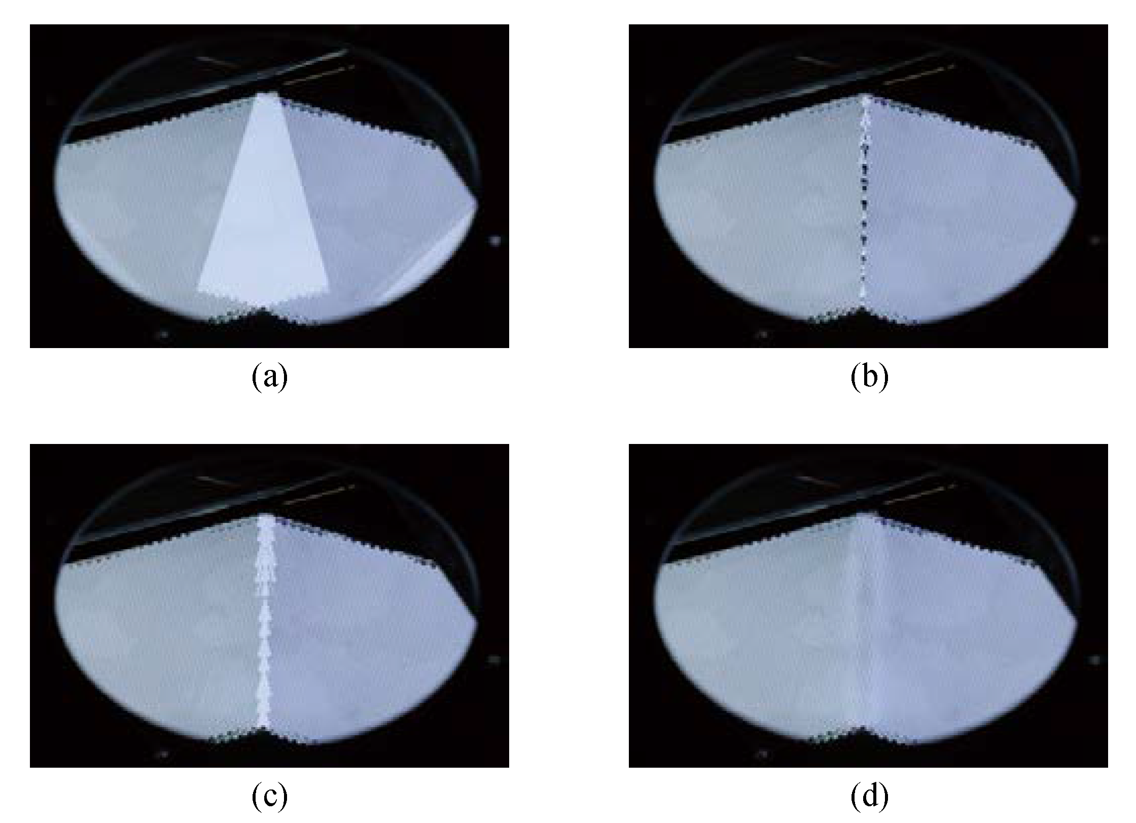
As shown in Figure 7a, when the image stitching technique was not used, the overlapping region of the two images became brighter when images were displayed on the adjacent LFDs. Figure 7b,c show the images when the image stitching technique was applied. When 3D images were displayed using the lenses that were completely included in the trapezoids, a black line was observed along the connecting lines, as shown in Figure 7b. When 3D images were displayed using the lenses that were completely or partly included in the trapezoids, a bright line was observed along the connecting lines, as shown in Figure 7c. Thus, 3D images were displayed using trapezoids expanded by five lenses, and we used the bilinear interpolation technique to connect the two trapezoid regions. The resultant image is shown in Figure 7d. The two images were smoothly stitched.
In the case of stitching skewed 2D displays, any image correction technique can provide continuous images only for a specified viewing direction. However, when skewed LFDs are stitched, the images are continuously connected along the connecting lines because the directions of the rays are properly controlled by all displays. Since the ray directions of all LFDs were calibrated by the technique described in Section 4, no additional image correction technique was required to stitch the skewed LFDs.
6. Brightness Matching Technique between Upper and Lower LFDs
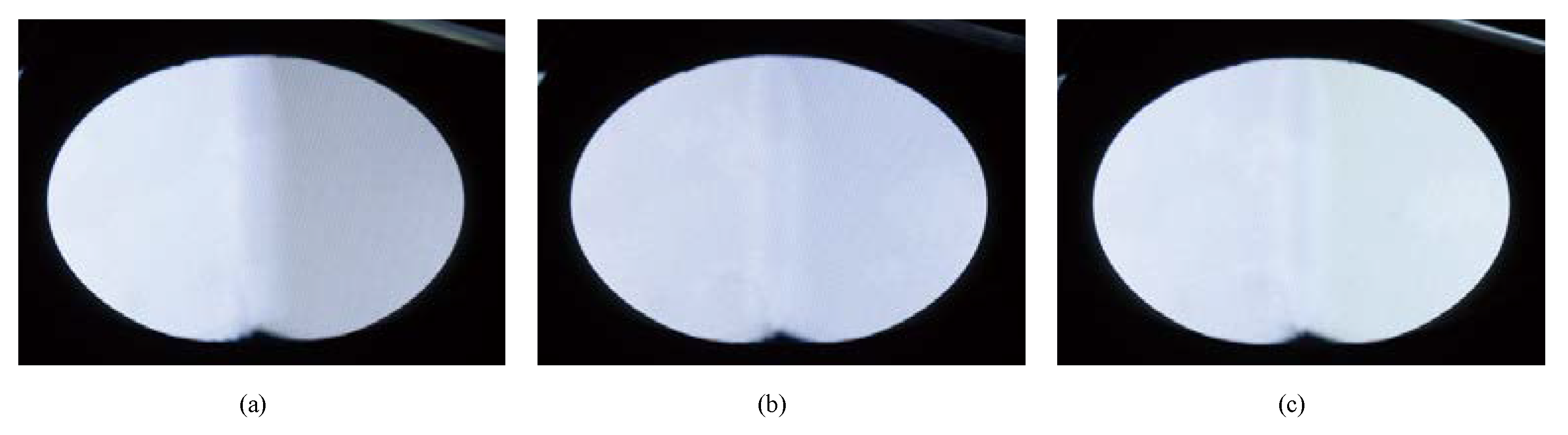
A half mirror was used to integrate 3D images produced by the upper and lower LFDs. A metallic half mirror was used for the light field Mirage, as described in Section 3. Because light emitted from the LCDs is linearly polarized and is made incident into the half mirror at an angle of 45°, the reflectance and transmittance of the metallic half mirror for light emitted from the upper and lower LFDs are not equal. Therefore, the 3D image ray intensities from the upper and lower LFDs are different. Figure 8a shows the intensity difference in the stitched images observed through the top hole. The left half image was generated by one of the upper LFDs, and the right half image was generated by one of the lower LFDs. The average luminance was 67.5 cd/m2 and 164.3 cd/m2 for the images generated by the upper LFDs and lower LFDs, respectively. The photographs shown in Figure 7 were captured by reducing the intensity of the upper LFDs to make the brightness of both images equivalent. In this case, the stitched images became dark. We developed the brightness matching technique to increase the brightness of the 360-degree images produced by the light field Mirage.
First, quarter-wave plates were used to make the light emitted from the upper and lower LFDs circularly polarized. The average luminance of images generated by the upper LFDs was increased to 106.0 cd/m2, and that of the images generated by the lower LFDs was reduced to 121.5 cd/m2. The stitched images are shown in Figure 8b. The brightness difference decreased, and the brightness of the stitched image increased.
Next, half-wave plates were attached to the upper and lower LFDs. For the upper LFDs, the half-wave plates were placed to make their polarization axes parallel to the polarized direction of linearly polarized light emitted from the LFDs so that the polarization of light emitted from the upper LFDs did not change. For the lower LFDs, the half-wave plates were placed to position their polarization axes at an angle of 45° against the polarized direction of the linearly polarized light emitted from the LFDs, so that the linearly polarized light rotated by an angle of 90°. The average luminance of images generated by the upper LFDs was increased to 143.8 cd/m2, and that of the images generated by the lower LFDs was reduced to 150.8 cd/m2. The stitched images are shown in Figure 8c. The brightness difference was reduced to 2.4%. The brightness of the stitched images increased by 2.2 times compared with that obtained without using the brightness matching technique. Therefore, we adopted the half-wave plates to the light field Mirage.
7. Generation of 360-Degree 3D Images
The calibration technique for LFDs, image stitching technique, and brightness matching technique were applied to the constructed light field Mirage consisting of eight LFDs.
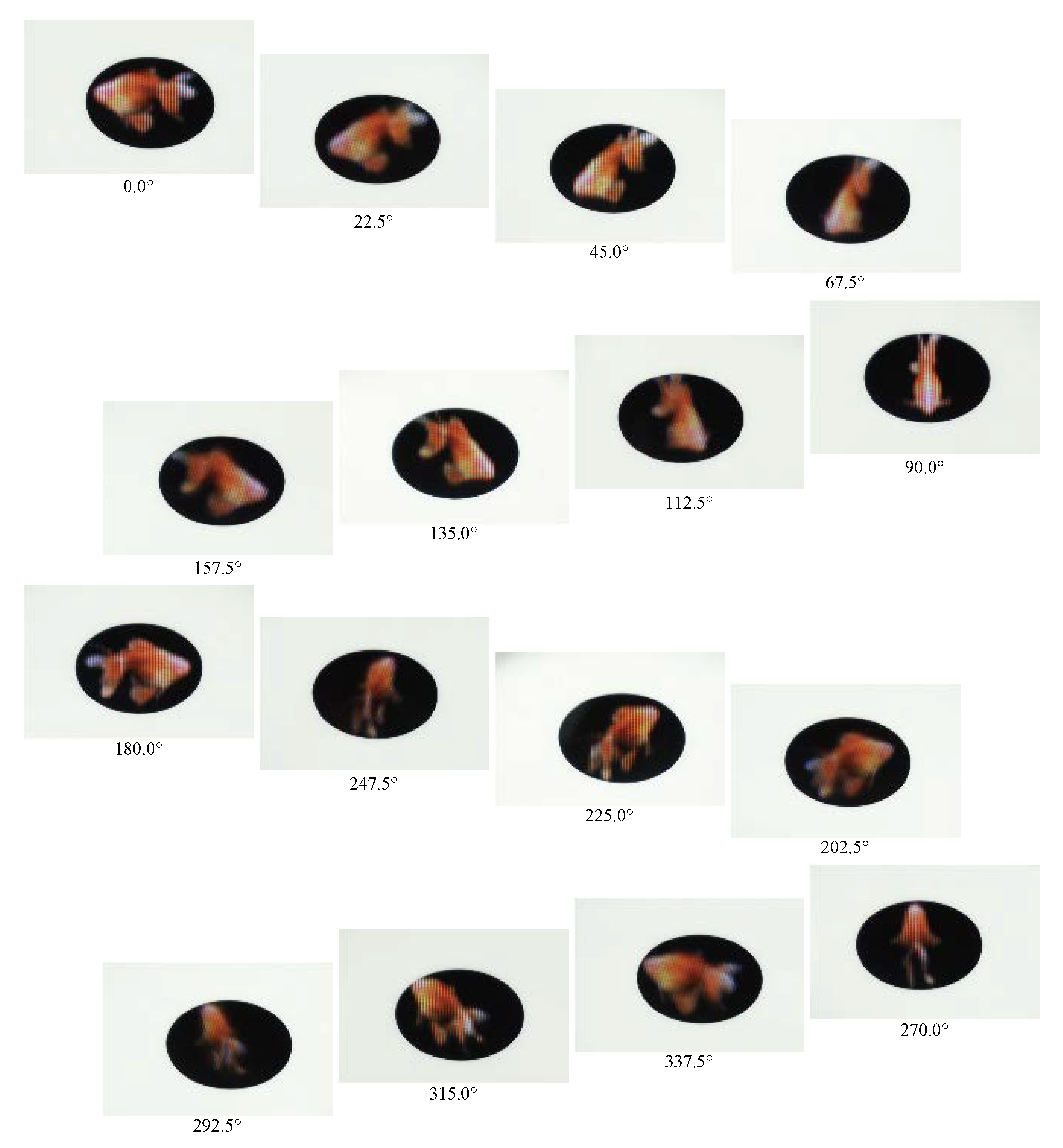
First, the 360-degree 3D image was generated using the display system configured for the non-tracking technique. The displayed object was a goldfish. Figure 9 shows photographs of the 3D images captured from 16 directions. The eight directions (0.0°, 45.0°, 90.0°, 135.0°, 180.0°, 225.0°, 270.0°, and 315.0°) were the directions normal to the screens of the eight LFDs, and the other eight directions (22.5°, 67.5°, 112.5°, 157.5°, 202.5°, 247.5°, 292.5°, and 337.5°) were the intermediate directions of the former eight directions. Because no double images were observed from any direction, the calibration technique worked well. The discontinuity of images was not observed from the intermediate directions due to the image stitching technique. The difference in image brightness was not noticeable by performing the brightness matching technique. The 360-degree 3D image could be observed.
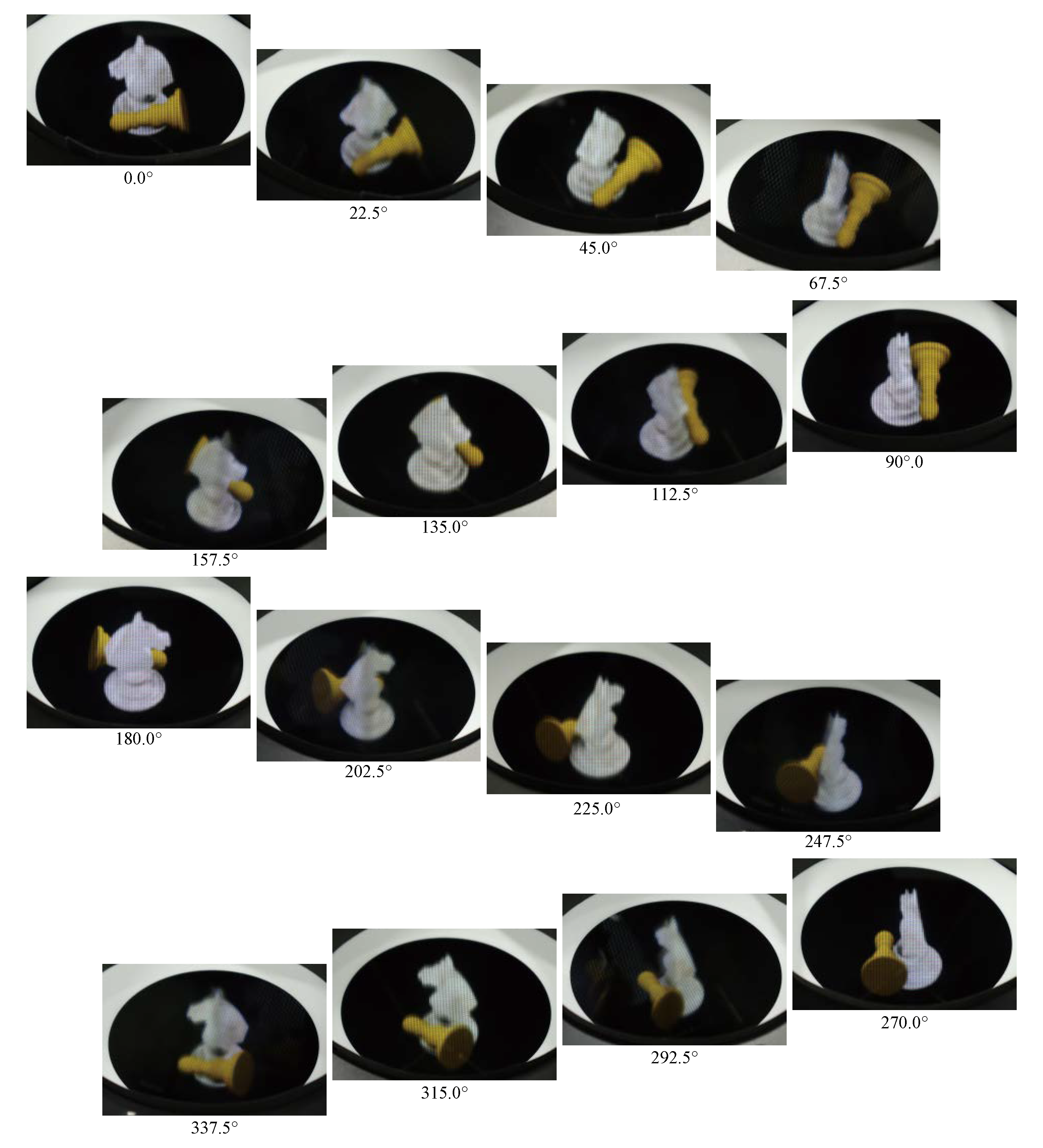
Then, the 360-degree 3D image was generated using the display system configured for the tracking technique. Instead of using an eye-tracking system, we assumed that the observer’s eye position was virtually tracked in the circular direction and the 3D images were produced in accordance with the virtual observer’s eye position. The displayed objects were chess pieces: a knight and pawn. Figure 10 shows photographs of the 3D images captured from the 16 directions used for the experiment of the non-tracking technique. No double images were observed from any direction, the discontinuity of images was not observed from the intermediate directions, and the difference in the brightness of the images was not obvious. Therefore, the three proposed techniques worked for both the tracking and non-tracking systems.
As shown in Figure 9 and Figure 10, respectively, in both the non-tracking and tracking methods, 3D images at directions normal to the screens tend to have a higher resolution than those at the intermediate angles. The 3D images at the intermediate angles overlapped two LFDs that had CDPs in different planes. The result of viewing angle differences in 3D image resolutions suggest that this is caused because the resolution-prioritized 3D image quality depends on the distance from the CDP.
8. Conclusions
To verify the system configuration of the light field Mirage that we proposed [1], a 360-degree 3D display system was designed and constructed. The prototype display system consisted of eight LFDs, and the diameters of the display screen were 24.2 mm and 78.0 mm for the non-tracking and tracking modes, respectively.
This study also developed a systematic alignment technique specialized for the light field Mirage to take advantage of the small number of display devices required for the display system, which consisted of three consecutive techniques. The calibration technique reduced the image mismatch among the eight displays by mechanical means and the residual mismatch was calibrated by electronic image processing. The image stitching technique enabled a smooth image connection between adjacent LFDs. The brightness matching technique reduced the brightness difference among the eight LFDs to 2.4%. Finally, 360-degree 3D images were successfully generated by the constructed light field Mirage.
Author Contributions
Conceptualization, Y.T. and Y.M.; methodology, Y.T. and Y.M.; software, K.Y. and Y.M.; validation, K.Y.; formal analysis, Y.T., K.Y. and Y.M.; investigation, K.Y.; resources, Y.M., Y.Y. and A.S.; data curation, K.Y.; writing—original draft preparation, Y.M.; writing—review and editing, Y.T.; visualization, K.Y. and Y.M.; supervision, Y.Y., A.S. and Y.T.; project administration, Y.T.; funding acquisition, Y.Y. and A.S. All authors have read and agreed to the published version of the manuscript.
Funding
This research received no external funding.
Institutional Review Board Statement
Not applicable.
Informed Consent Statement
Not applicable.
Data Availability Statement
Not applicable.
Conflicts of Interest
The authors declare no conflict of interest.
References
- Momonoi, Y.; Yamamoto, K.; Yokote, Y.; Sato, A.; Takaki, Y. Light field Mirage using multiple flat-panel light field displays. Opt. Express 2021, 29, 10406–10423. [Google Scholar] [CrossRef] [PubMed]
- Kitamura, Y.; Konishi, T.; Yamamoto, S.; Kishino, F. IlluaionHole: An Interactive Stereoscopic Display System for Multiple Users. J. Inst. Image Inf. Telev. Eng. 2003, 57, 1320–1327. [Google Scholar]
- Yendo, T.; Kawakami, N.; Tachi, S. Seelinder: The cylindrical lightfield display. In Proceedings of the ACM SIGGRAPH 2005 on Emerging Technologies, Los Angeles, CA, USA, 31 July–4 August 2005; p. 16-es. [Google Scholar]
- Yendo, T.; Fujii, T.; Tanimoto, M.; Tehrani, M.P. The Seelinder: Cylindrical 3D display viewable from 360 degrees. J. Vis. Commun. 2010, 21, 586–594. [Google Scholar] [CrossRef]
- Miyazaki, D.; Akasaka, N.; Okoda, K.; Maeda, Y.; Mukai, T. Floating three-dimensional display viewable from 360 degrees. In Proceedings of the Stereoscopic Displays and Applications XXIII, Burlingame, CA, USA, 23–25 January 2012; Volume 8288. [Google Scholar]
- Miyazaki, D.; Miyazaki, G.; Maeda, Y.; Mukai, T. Floated integral imaging display viewable from surrounding area. In Imaging and Applied Optics 2014; OSA Technical Digest (online); Optical Society of America: Washington, DC, USA, 2014; paper DW2B.5. [Google Scholar]
- Butler, A.; Hilliges, O.; Izadi, S.; Hodges, S.; Kim, D.; Kong, D. Vermeer: Direct interaction with a 360° Viewable 3D Display. In Proceedings of the 24th Annual ACM Symposium on User Interface Software and Technology, Santa Barbara, CA, USA, 16–19 October 2011; pp. 569–576. [Google Scholar]
- Takaki, Y.; Uchida, S. Table screen 360-degree three-dimensional display using a small array of high-speed projectors. Opt. Express 2012, 20, 8848–8861. [Google Scholar] [CrossRef] [PubMed]
- Uchida, S.; Takaki, Y. 360-degree three-dimensional table-screen display using small array of high-speed projectors. In Proceedings of the Stereoscopic Displays and Applications XXIII, Burlingame, CA, USA, 23–25 January 2012; Volume 8288. [Google Scholar]
- Yoshida, S.; Kawakita, M.; Ando, H. Light-field generation by several screen types for glasses-free tabletop 3D display. In Proceedings of the 2011 3DTV Conference on the True Vision-Capture, Transmission and Display of 3D Video, Antalya, Turkey, 16–18 May 2011; pp. 1–4. [Google Scholar]
- Yoshida, S. fVisiOn: Glasses-free tabletop 3-D display–its design concept and prototype–. In Digital Holography and Three-Dimensional Imaging; OSA Technical Digest (CD); Paper DTuA1; Optical Society of America: Washington, DC, USA, 2011. [Google Scholar]
- Yoshida, S. fVisiOn: 360-degree viewable glasses-free tabletop 3D display composed of conical screen and modular projector arrays. Opt. Express 2016, 24, 13194–13203. [Google Scholar] [CrossRef] [PubMed]
- Yoshida, S. Virtual multiplication of light sources for a 360°-viewable tabletop 3D display. Opt. Express 2020, 28, 32517–32528. [Google Scholar] [CrossRef] [PubMed]
- Makiguchi, M.; Kawakami, T.; Sasai, M.; Takada, H. Smooth motion parallax glassless 3D screen system using linear blending of viewing zones and spatially imaged iris plane. In Proceedings of the SID Symposium Digest of Technical Papers, Los Angeles, CA, USA, 20–25 May 2018; Volume 48, pp. 903–906. [Google Scholar]
- Makiguchi, M.; Takada, H.; Fukiage, T.; Nishida, S. Reducing image quality variation with motion parallax for glassless 3D screens using linear blending technology. In Proceedings of the SID Symposium Digest of Technical Papers, Los Angeles, CA, USA, 20–25 May 2018; Volume 49, pp. 251–254. [Google Scholar]
- Makiguchi, M.; Takada, H.; Kawakami, T.; Sasai, M. 360-degree tabletop type 3D screen system using linear blending of viewing zones and spatially imaged iris plane. In Proceedings of the SID Symposium Digest of Technical Papers, San Jose, CA, USA, 1 June 2019; Volume 50, pp. 585–588. [Google Scholar]
- Yu, X.; Xinzhu, S.; Gao, X.; Binbin, Y.; Duo, C.; Boyang, L.; Li, L.; Chao, G.; Wang, P. 360-degree tabletop 3D light-field display with ring-shaped viewing range based on aspheric conical lens array. Opt. Express 2019, 27, 26738–26748. [Google Scholar] [CrossRef] [PubMed]
- Gao, X.; Sang, X.; Yu, X.; Zhang, W.; Yan, B.; Yu, C. 360° light field 3D display system based on a triplet lenses array and holographic functional screen. Chin. Opt. Lett. 2017, 15, 121201. [Google Scholar]
- Momonoi, Y.; Yamamoto, K.; Yokote, Y.; Sato, A.; Takaki, Y. Flipping-free Light Field Mirage Using Multiple Light Field Displays. In Proceedings of the SID Symposium Digest of Technical Papers, Online, 17–21 May 2021; Volume 52, pp. 657–660. [Google Scholar]
- Jang, J.S.; Jin, F.; Javidi, B. Three-dimensional integral imaging with large depth of focus by real and virtual image fields. Opt. Lett. 2003, 28, 1421–1423. [Google Scholar] [CrossRef] [PubMed]
- Jin, F.; Jang, J.S.; Javidi, B. Effects of device resolution on three-dimensional integral imaging. Opt. Lett. 2004, 29, 1345–1347. [Google Scholar] [CrossRef] [PubMed]
- Hoshino, H.; Okano, F.; Isono, H.; Yuyama, I. Analysis of resolution limitation of integral photography. JOSA A 1998, 15, 2059–2065. [Google Scholar] [CrossRef]
Figure 1.
Schematic of light field Mirage: (a) side view and (b) top view.

Figure 2.
Elimination of repeated 3D images: (a) non-tracking technique and (b) tracking technique.

Figure 3.
Constructed light field Mirage consisted of eight LFDs.

Figure 4.
Adjustments of positions of eight LFDs using grid patterns displayed by all LFDs on (a) CDP and (b) plane above CDP with a length of 14 mm.
Figure 4.
Adjustments of positions of eight LFDs using grid patterns displayed by all LFDs on (a) CDP and (b) plane above CDP with a length of 14 mm.

Figure 5.
Electronic calibration of eight LFDs using grid patterns displayed by all LFDs on (a) CDP and (b) plane above CDP with a length of 14 mm.
Figure 5.
Electronic calibration of eight LFDs using grid patterns displayed by all LFDs on (a) CDP and (b) plane above CDP with a length of 14 mm.

Figure 6.
Stitching of screens of LFDs (top view and drawn in an orthographic projection).

Figure 7.
Effects of image stitching technique: (a) without image stitching, (b,c) with image stitching and without image interpolation, and (d) with image stitching and image.
Figure 7.
Effects of image stitching technique: (a) without image stitching, (b,c) with image stitching and without image interpolation, and (d) with image stitching and image.

Figure 8.
Effects of brightness matching technique: (a) without brightness matching, with brightness matching using (b) quarter-wave plates, and (c) hale-wave plates.
Figure 8.
Effects of brightness matching technique: (a) without brightness matching, with brightness matching using (b) quarter-wave plates, and (c) hale-wave plates.

Figure 9.
The 360-degree 3D image generated by non-tracking technique observed from 16 directions.

Figure 10.
The 360-degree 3D image generated by tracking technique observed from 16 directions.

Publisher’s Note: MDPI stays neutral with regard to jurisdictional claims in published maps and institutional affiliations. |
© 2022 by the authors. Licensee MDPI, Basel, Switzerland. This article is an open access article distributed under the terms and conditions of the Creative Commons Attribution (CC BY) license (https://creativecommons.org/licenses/by/4.0/).
Share and Cite
MDPI and ACS Style
Momonoi, Y.; Yamamoto, K.; Yokote, Y.; Sato, A.; Takaki, Y. Systematic Approach for Alignment of Light Field Mirage. Appl. Sci. 2022, 12, 12413. https://0-doi-org.brum.beds.ac.uk/10.3390/app122312413
AMA Style
Momonoi Y, Yamamoto K, Yokote Y, Sato A, Takaki Y. Systematic Approach for Alignment of Light Field Mirage. Applied Sciences. 2022; 12(23):12413. https://0-doi-org.brum.beds.ac.uk/10.3390/app122312413
Chicago/Turabian StyleMomonoi, Yoshiharu, Koya Yamamoto, Yoshihiro Yokote, Atsushi Sato, and Yasuhiro Takaki. 2022. "Systematic Approach for Alignment of Light Field Mirage" Applied Sciences 12, no. 23: 12413. https://0-doi-org.brum.beds.ac.uk/10.3390/app122312413
Note that from the first issue of 2016, this journal uses article numbers instead of page numbers. See further details here.