


ROS-Based Condition Monitoring Architecture Enabling Automatic Faults Detection in Industrial Collaborative Robots


Dipartimento di Ingegneria dell’Informazione (DII), Università Politecnica delle Marche, 60131 Ancona, Italy
*
Author to whom correspondence should be addressed.
Appl. Sci. 2023, 13(1), 143; https://0-doi-org.brum.beds.ac.uk/10.3390/app13010143
Submission received: 6 October 2022
/
Revised: 9 December 2022
/
Accepted: 20 December 2022
/
Published: 22 December 2022
(This article belongs to the Special Issue Robots Dynamics: Application and Control)
Abstract
:Featured Application
This work aimed to enhance the current state of the art regarding the Condition Monitoring of industrial collaborative manipulators providing a general architecture which can be used in many different industrial scenarios. This solution is helpful in overcoming current limits regarding the definition of algorithms for the automatic detection of failures in collaborative robots working on flexible manufacturing.
Abstract
The Condition Monitoring (CM) of industrial collaborative robots (cobots) has the potential to decrease downtimes in highly automated production systems. However, in such complex systems, defining a strategy for effective CM and automatically detecting failures is not straightforward. In this paper, common issues related to the application of CM to collaborative manipulators are first introduced, discussed, and then, a solution based on the Robot Operating System (ROS) is proposed. The content of this document is highly oriented towards applied research and the novelty of this work mainly lies in the proposed CM architecture, while the methodology chosen to assess the manipulator’s health is based on previous research content. The CM architecture developed and the relative strategy used to process data are useful for the definition of algorithms for the automatic detection of failures. The approach is based on data labeling and indexing and aims to extract comparable data units to easily detect possible failure. The end of this paper is provided with a proof of concept (PoC) applied to an industrial collaborative manipulator where the proposed CM strategy has been implemented and tested in a real application scenario. Finally, it is shown how the proposed methodology enables the possibility of defining standard Health Indicators (HIs) to detect joint anomalies using torque information even under a highly dynamic and non-stationary environmental conditions.
1. Introduction
The advent of Industry 4.0 concepts has brought about a new way of ensuring machine availability, namely Condition Monitoring (CM). This method involves the continuous monitoring of machine data to detect wear, making it easier to schedule repairs and thus reduce downtime. For some kinds of components (i.e., electric motors, speed reducers, gears, bearings, etc., used in many types of machinery), CM methods have been extensively investigated and effectively adopted in industrial environments. However, difficulties in defining effective CM methods arise in the case of systems such as industrial robots or more specifically collaborative robots (cobots). This is because their kinematic chain is comprised of several mechanical components which, even if they have been extensively studied individually, have superimposed effects in a single system that can significantly increase the complexity of defining a reliable CM strategy. Moreover, in the case of cobots, the complexity increases since these are generally used in flexible manufacturing where they perform dynamic tasks driven by programmable motions rather than fixed tasks, in contrast with standard industrial robots. This means that the same cobot can be used in a single working day for different tasks executing two to three or more programs, each of which is composed of tens to hundreds of motion command combinations. Therefore, in such systems, obtaining useful data to diagnose and predict failures is not straightforward for different aspects and it is currently a challenging topic in the industry. Among various kinds of cobots, this work will be focused on CM for collaborative manipulators, and during the rest of the document, when using the term “cobots”, we will refer to this category. In this regard, this document intends to provide a solution to contribute to the definition of an open source CM architecture based on Robot Operating System (ROS) and to solve some problems related to determining automatic fault detection algorithms in collaborative manipulators. One of the main focuses of this work is providing a technological solution for CM with collaborative manipulators in situations of industrial interest and for this reason, the content of this document is highly oriented to applied research. In this regard, the novelty of this work mainly lies in the proposed CM architecture, while the methodology chosen to assess the manipulator’s health is based on previous research content. The CM can be stated as a hot topic with a lot of research and industry interests considering the current challenges and opportunities in the human–robot collaboration context [1], also regarding solutions based on augmented reality and virtual reality [2]. Going into more detail, another issue to point out is what kind of sensor is the best suited for assessing the health of cobots and which is the best strategy to collect that information. In fact, if data that we decide to analyze are already available in the system, there is the need to use a device to communicate with the robot controller, otherwise data acquisition must be managed by using external sensing units. To sum up, issues related to the application of CM to cobots can be split into three macro areas:
- Obtain system data. In order to choose which data to monitor to evaluate the health of cobot components, there is the need to answer precise questions: which data are useful for healthily evaluating the system? Which components do we need to monitor in order to avoid production stops and how do we obtain that information? The answers to these questions can fundamentally lead to two possibilities, the use of sensors already installed into the system or the use of external sensors. In the first case, there is a need to establish a connection with the industrial controllers to access sensing data (for instance, motor currents, joint positions, speeds, torques etc.). In the second case, however, there is a need to use a device to manage the acquisition of data from extra sensing units installed on the robot (for instance, the accelerometer, and the acoustic and laser sensors). As is easy to imagine, in the industry, the choice falls on the first solution as less expensive, given that it does not require other external components. Moreover, using the controller’s data allows for the definition of a common strategy valid in all systems which use that controller. Finally, the communication protocols used to exchange information with controllers are robust, and thus with a lesser possibility of losing data. Based upon these considerations, this work presents in Section 3.1 an ROS-based CM architecture running in a Linux system which enables the possibility of obtaining signals from industrial controllers.
- Acquire, collect and store data. The common questions that we need to answer to obtain a consistent dataset from which to extract information for further analysis are the following: How to manage the data acquisition phase? Which rules do we need to use to collect, organize and store data? To answer these questions, there is a need to go deeper into the details of a cobot application; however, it is easy to understand that it is not trivial to decide on a strategy to acquire data in a system that performs different combinations of movements, reaching many different positions at different speeds, sometimes carrying different payloads, all in the same program. In fact, those systems are thought of for flexible production and may be used for many different tasks contemporary. Therefore, in Section 3.3, we propose a methodology to solve these issues and we test its validity in a case study application common in Industrial scenarios in Section 4.
- Analyze and detect abnormal data. This area is the one that affects the reliability of a CM system, and the related question is: Which method do we need to use to automatically extract information on the system’s health? Furthermore, answering this question is not straightforward since there lots of valid techniques have been proposed in the literature. Generally, these are divided into model-based, signal-based and data-driven and they have proven their validity in many different scenarios. Fundamentally, we need to keep in mind that the methodology chosen should be the one that decreases the number of missed and false fault detection. However, this also depends on the kind of failure in the system we want to detect. In this paper, regarding the case study, we proposed a solution based on common health indicators (HIs) that are well-known in this area, considering that the purpose of this paper is to define a general CM architecture which can be applied to different collaborative robots involved in flexible manufacturing. For this reason, this work is not going to be focused on defining the best strategy for detecting failures but on how to automate this process.
The following sections will be devoted to expanding the debate about these common issues regarding fault detection in collaborative manipulators. The methodology chosen in this work to assess manipulator health will be presented after introducing recent arts in this context in Section 2. While the developed CM architecture will be discussed in Section 3, it also proposes a systematic criterion for organizing data in order to obtain reliable algorithms for automatic fault detection in cobots. In summary, this work aims to address these previously introduced problems by proposing a new Condition Monitoring architecture. This solution is valid for defining an automatic failure detection strategy in industrial collaborative robots to support flexible manufacturing. The CM architecture is based on the ROS framework with the potential of being adaptable for many different industrial cobot brands. In particular, the studies in this paper were conducted to test the CM architecture on an Omron TM cobot. In this regard, in a dedicated section, we introduce the ROS package for Omron TM robots [3], developed and tested in collaboration with the Omron Europe Robotics team. The remainder of the paper is organized as follows: Section 2 presents relevant work in the field of CM of industrial robots, Section 3 discusses the ROS-based CM architecture presenting the conceptual idea and the methodology behind the proposed approach, while Section 4 presents the results regarding the application of the proposed CM architecture using the Omron TM5-900 collaborative robot in a case study. Finally, the paper’s conclusions along with future works of investigation are summarized in Section 5.
2. Related Work
When talking about Condition Monitoring, Fault Detection or Predictive Maintenance in Industrial Robots, more specifically in manipulators, we face the problem of choosing the best sensor and technique to detect and if possible prediction failures may lead to production stops with relative downsides. As discussed during the Introduction, there are two crucial aspects to take into account: (1) there are several mechanical components in a single system and considering their effects together increases the difficulty in analysis; and (2) the same system can be used for many different tasks, making it hard to define a method that may work under every possible working condition. Regarding the first aspect, the mechanical components most affected by failures are the robot joints [4,5,6]. Problems are generally related to the electric motor or to the speed reducer and specifically to some particular part of these two components (i.e., motor windings, bearings, shaft, breaks, gears of the reducer, etc.). Sensor data that mainly have provided the best results in this context are motor current, motor torque, or vibrations [7], also used sometimes in combination with other system states. For instance, Xu et al. developed a detection method for the bolt loosening of industrial robot joints based on electromechanical modeling and motor current signature analysis (MCSA) [8]. Raouf et al. in [9] proposed prognostic health management for the robotic rotate vector reducer using external sensors mounted on the robot and managed using an embedded system to electrical MCSA for mechanical fault detection. Nentwich et al. proposed a new method to evaluate the health indicators for industrial robots and suggest a new health indicator (HI) based on vibration data measurements [10]. In Ref. [11], an Experimental Comparison of Anomaly Detection Methods for Collaborative Robot Manipulators is proposed using different information (i.e., joints current, torque, speed, etc.). In particular, they compare 15 methods for anomaly detection, including methods based on principle component analysis, local outlier factor, and autoencoders assessed in a typical pick-and-place application with respect to their capacity to detect a broad range of exogenous anomalies. Izagirre et al. proposed a non-intrusive methodology for industrial robot joint health assessment using torque sensor data by creating a digital signature given a defined trajectory and load combination. The signature of each individual robot is later used to diagnose mechanical deterioration [12]. In Ref. [13], the authors proposed a Gaussian mixture model-based unsupervised fault detection framework to detect the faults in industrial robots using current signals. In Ref. [14], they used torque estimation for gearbox failure in industrial robots proposing an improvement of detection performance with respect to machine learning approaches using a technique to curate the data prior to building a classification model. While in [15], the authors proposed a design method of trajectories for detecting the excessive clearances of passive joints in a DELTA robot on the basis of the phenomenon that the actuation torque waveform fluctuates due to the collision between joint elements. Based on these previous work considerations, our approach will be based on Motor Torque Analysis (MTA), since in the authors’ experience, torque analysis also provided interesting results regarding the diagnosis under non-stationary conditions (i.e., varying speed and load conditions) [16]. In fact, in [17], we already pointed out the possibility of overcoming limits related to bearing fault diagnosis under non-stationary conditions using MTA instead of MCSA. Furthermore, in [18], a review regarding the detection and diagnosis methodologies for gearboxes, it is demonstrated that the most useful signals for diagnosis are currents, torques, or vibrations. Since the manipulators’ joints are composed of electric drives and speed reducers also for these cobots, the same considerations above may be considered valid. Moreover, with respect to vibrations, torque information is already available in robots’ controllers and there is no need to install an external device on the cobot. This solution is also preferable for industrial environments where it is difficult to isolate external vibrations from vibrations caused by a robot’s failure. In Refs. [19,20,21], it is possible to have a complete overview of proprioceptive and exteroceptive sensors used in collaborative robot applications. Therefore, our approach will be focused on developing a ROS CM architecture to communicate with the robot’s controller. Regarding the second issue, most papers, to the best of the authors’ knowledge, propose specific solutions that are mainly valid for the particular case study. In fact, previous work in industrial or collaborative robot fault diagnostics has the limit of being built for specific motion sequences or programs and may not accurately or consistently detect faults in other motions, due to discrepancies (different positions, speeds, loads, etc.). For instance, some papers present results in applications where the system is used in repetitive tasks [5,11,22,23] (e.g., machine tending, pick and placing, etc.) or average values are considered to take into account the speed and load variability on similar applications [14] or in some cases, the isolated movement of a single axis is performed during measurement [10,24]. Furthermore, because most of them are applied to standard industrial robots used in repetitive tasks and not to collaborative robots generally used for flexible manufacturing. However, the repeatability of the task or other assumptions relative to a specific application allows defining methodologies to trigger signal acquisition under precise system conditions (same motion command, same load conditions, same speed, etc.) obtaining comparable datasets. Then, by comparing those data in the case of healthy and faulty conditions, it is possible to identify a failure pattern and apply a methodology for the automatic detection of failure. Furthermore, our previous work was based on a similar assumption, since we were applying a detection technique in a cartesian robot used in a repetitive pick and place application [25]. Differently, in the case of cobots, solutions such as that would be ineffective, since most of the time we do not have repeatability in motion commands or rather only in certain conditions. Therefore, there is a need to define a strategy to organize data before analyzing them to find hypothetical defecting features. A different approach was proposed by Park Ye-Seul et al. [26], named “Programmable Motion-Fault Detection”, which is useful for detection in Collaborative Robot through the analysis of motion residuals. The proposed approach is based on three steps: construct a data model that can hierarchically analyze the relationships between sensing values and cobot operation information, analyze data correlations between the sensing data and operation data to track programmable motions with anomalies and lastly, and define the detection criteria of a programmable motion-fault by statistically analyzing the sensing values with the same program and motion. This work tries to solve similar issues related to the definition of a methodology for detection valid under different working conditions, however, their fault diagnosis verification may not accurately represent a real-world industrial facility environment since it was tested in a simulated dataset. For this purpose, our work will be focused on the development of a methodology to enhance the current state of the art regarding the condition monitoring of industrial collaborative manipulators providing a general architecture which can be used in many different industrial scenarios. In the following part, the theoretical background regarding the methodology chosen to detect failures in manipulators and which will be used to assess joint health is introduced and discussed. In the next section, the ROS-based CM architecture which can be considered modular and adaptable to different robotic systems used for dynamic tasks is presented.
Joint Health Assessment via Torque Analysis
In this work, the proposed CM architecture is used to assess manipulator joint health using torque signals. The choice of monitoring joint health is because manipulators may fall into fault status after enduring long-term heavy manipulations, preventing the accurate completion of the desired industrial tasks. Among various valid techniques to monitor joint health, such as the one based on vibrations, or current measurements, this paper focuses on the use of the system proprioceptive sensor to achieve a non-intrusive methodology. In particular, the torque information is generally available in collaborative manipulators because it is also used for limiting the forces expressed by the system in the case of collisions. Since each manipulator’s joint is mechanically constructed in the same way, composed of an electric motor and a speed reducer, it is possible to consider a manipulator as a sum of different electric motors and speed reducers. Based on this assumption, it is possible to exploit some considerations derived from electric motors. When mechanical failures arise in the motor or in the transmission system attached to the motor shaft, there are load torque oscillations caused by the malfunction, as demonstrated in [27]. In particular, the load torque () of a rotating machine under a mechanical fault (e.g., bearing fault, mechanical unbalance, gear defects, etc.) can be modeled as the sum of constant components (, which represents the load of the motor) and a time-varying term which depends on the characteristic frequency (which represents an order of the rotational frequency of the rotor ). The varying component represents the amount of load torque that arises in case of mechanical defect. Generally, it is modeled using only the first term of the Fourier series because higher-order terms are negligible [27]:
where is the amplitude of the load torque oscillation and contains the fault characteristic frequency , also called a rotational frequency order. An order refers to a frequency that is a certain multiple of a reference rotational speed (). For a rotating system, the primary shaft rotation () drives the fundamental frequency, , where R is the order’s ratio. For instance, if we have a defecting gear connected to the rotor shaft which reduces the speed ratio by 5, in the steady-state, we would have a faulty component in the vibration or current or torque spectrum. However, in the case of non-stationary application (varying speed of the motor and loads), we are no longer expecting precise defecting frequencies since is changing over time but we can still evidence an increment of the load torque value. Thus, under a mechanical fault, the mechanical equation of an electric motor can be written as:
where J is the motor rotor inertia, is the electromagnetic torque produced by the motor, B represents the coefficient of viscous friction, and is the motor rotor speed. Thus, when the manipulator is working in a healthy state (), the motor’s joint produces a certain torque to fulfill the motion request during program execution. However, when a joint is under a mechanical defect (), in order to accomplish the task the motor needs to provide an increasing amount of torque () to compensate for the mechanical defect. Thus, in the torque signal, it is expected that an increasing value can be evaluated to assess the joint health. These considerations were also experienced in [12,22] where the torque signal was used to analyze the root cause of faulty joints. Thus, if mechanical wear has a significant effect on the effort of the joint, the hypothesis is that the faulty joint would require higher torque than a healthy joint to execute a given trajectory and the methods selected to identify a faulty joint, in this paper, will focus then on evaluating the increment in the torque applied in the robot joints. Further details regarding the methodology to evaluate changes in torque signals will be given when presenting the case study, while the next Section presents the CM architecture developed to apply the proposed methodology to a real industrial application.
3. Presenting a ROS-Based Condition Monitoring Architecture
As briefly discussed in Section 1, the data are fundamental for monitoring robots’ conditions. The possibility of reducing maintenance costs and downtimes using data that already available in the robotic systems without the need to install extra sensors is in the interest of the industry. For this purpose, using the ROS framework, it is possible to establish communication with industrial controllers to access available data. The choice of defining a CM strategy using ROS has the potential of being adaptable to many kinds of industrial controllers and robotics systems. This allows one to easily reuse already developed codes and testing them in many different robotics applications, quickly transferring from one system to another. Moreover, since ROS is open source, many tools and codes are already available to the community, allowing anyone to quickly implement projects and adjustments to derive a prototype in days. In this section, we present our CM architecture which is useful for the automatic detection of malfunctions in cobots used for dynamic tasks. The proposed solution has been developed to work with the controller of the Omron TM cobots family, which comprises manipulators of different sizes and weights. The CM architecture uses the ROS package for Omron TM robots developed to:
- Enable communication between the Omron TM controller and a Linux system in which the ROS master is running.
- Send motion commands through a Python Application Programming Interface (API) which uses open source trajectory planners.
- Enable the use of grippers and the possibility of simulating robotics applications using Gazebo.
- Read and storing controller data using Python libraries to manage the acquisition (i.e., rospy, pickle)
3.1. Omron TM Robots ROS Package
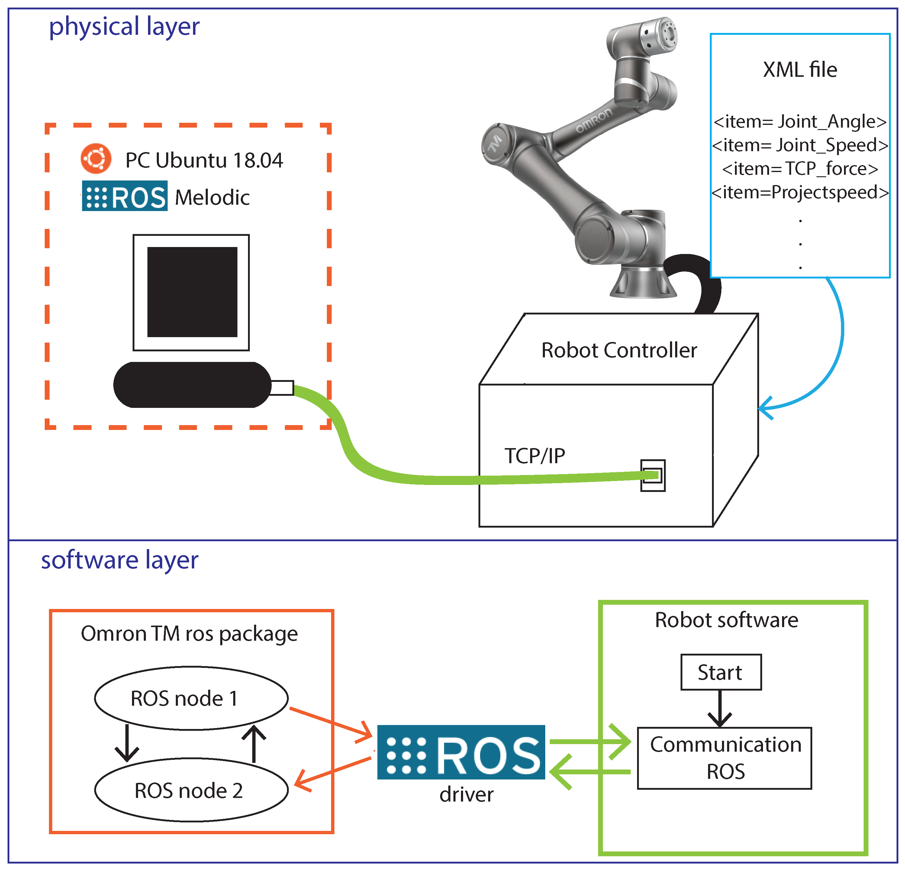
The developed Omron TM ROS package is available on GitHub and specific details can be found in [3]. This package uses a C++ driver which creates a single ROS node to enable topics and services to communicate with the controller. The communication is based on Ethernet Slave TCP/IP protocol and uses a client/server framework. Once enabled, the robot establishes a Socket TCP listener server to send the robot status and data to all connected clients or receive the contents from the clients to execute instructions. In Figure 1, it is possible to see a schematic overview of the described connection. In order to exchange information with the controller, we upload an XML file to the robot controller, selecting which cobot states we want to access (Figure 1). The XML file specifies the data table transmitted by the ethernet slave (cobot) to the master (PC in which ROS is running). These data selected are accessible from any Linux system where the Omron TM robots ROS package is installed.
3.2. Conceptual Idea
Once the connection with the cobot as an Ethernet TCP/IP client is established, it is possible to read data or execute instructions (e.g., motion commands) using the Omron TM ROS package [3]. The idea is to develop a CM architecture that runs in parallel during the normal functioning of the cobot and define a methodology to automatically analyze data to detect anomalies or malfunctions in the system. However, as discussed during the introduction, there are many aspects to consider in order to achieve this goal. For this purpose, in this Section, first we analyze a simple program to understand critical points in defining a valid CM strategy showing an example of data acquisition. Then, a solution to obtain comparable data sequences that are useful for further fault detection and diagnosis is discussed and presented. Supposing that a simple program named “Test” made by a sequence of motion commands is executed by the robot, like the following:
- Point-to-point (PTP) motion from A to B;
- Line move from B to C;
- PTP motion from C to A;
- PTP motion from A to B;
- Line move from B to D;
- PTP motion from D to E;
- PTP motion from E to A;
- ... etc.
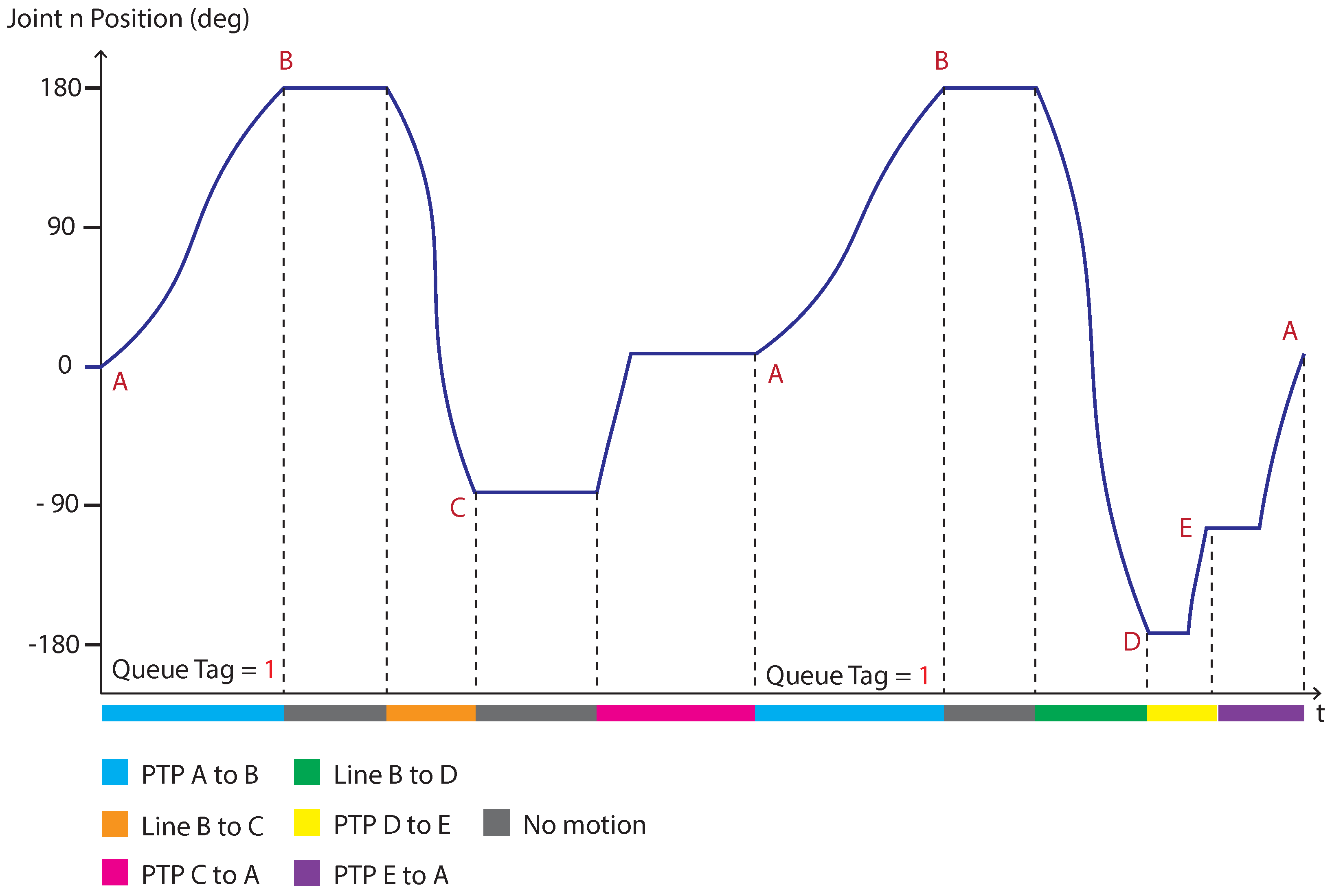
During the execution, we perform acquisitions of position data for a single joint n involved in these motions (Figure 2).
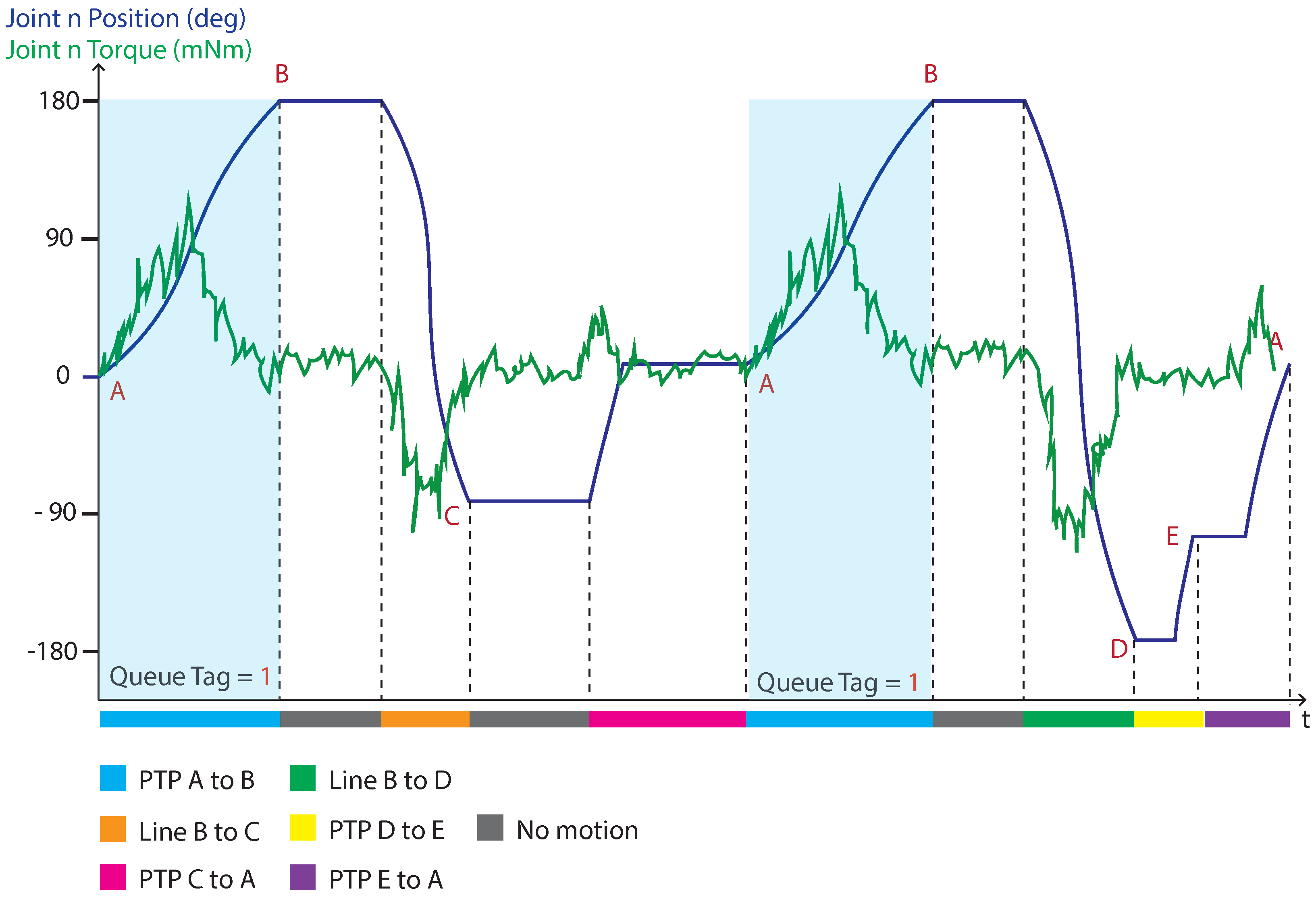
Referring to Figure 2, if we think to look for some kind of repeatability in the “Test” program, this can be found during the execution of the PTP motion from point A to B. In fact, as discussed in the Introduction, to identify faulty features, we need to compare data in healthy and faulty conditions. However, having comparable data means acquiring those data under certain working conditions (i.e., type of movement, speed, target positions, etc.), otherwise it becomes a struggle to define a technique for the automatic detection of anomalies. Just to clarify this last sentence, supposing now, to acquire the joint n torque position during the previously defined sequence of motions (Figure 3). It is possible to notice in Figure 3 that the torque signal shape is strictly related to the working conditions of the system and varies according to the movement executed by the cobot. Therefore, finding a way to analyze the entire signal and defining an algorithm to detect automatically defecting features (if any) taking into account every possible working condition becomes really difficult if not impossible. However, if we think to analyze the torque signal only under certain conditions (e.g., only when the system is executing the PTP motion from A to B), we can obtain comparable data sequences (blue highlighted parts of Figure 3). In this way, in the case of a joint n malfunction, detecting and identifying changes in the values of the joint n torque become easier. Hence, to solve this problem, in the next section, a method for extracting repetitive data sequences (named “units”) is studied for the automatic detection of anomalies based on data labeling and indexing.
3.3. Data Labeling and Indexing Method
Since collaborative robots are used in dynamic activities, it is necessary to establish systematic criteria for organizing data in order to obtain reliable algorithms for automatic fault detection. Therefore, in this section, we present a method to extract data units from data acquisitions based on labeling and indexing. Referring to the “Test” program discussed above, every time we want to send a motion command to the controller, we can add a queue tag (index) to denote the current robot motion in process and the status of each queue tag can be monitored. This process is generally used to be sure that the robot motion has been executed, however, in our approach, it is also used to index the current data acquisition. In fact, every time we perform acquisitions of the cobot states during normal functioning, we add some labels and indexes to characterize that data acquisition. This allows us to easily extract specific data units that belong to the same set (i.e., acquired under the same working conditions). In greater detail, the additional information (labels and indexes) that we add to every cobot’s states acquisition are the following:
- Name of the running program;
- Type of motion and tag;
- Program percentual speed execution;
- Estimated tool center point (TCP) force along Z.
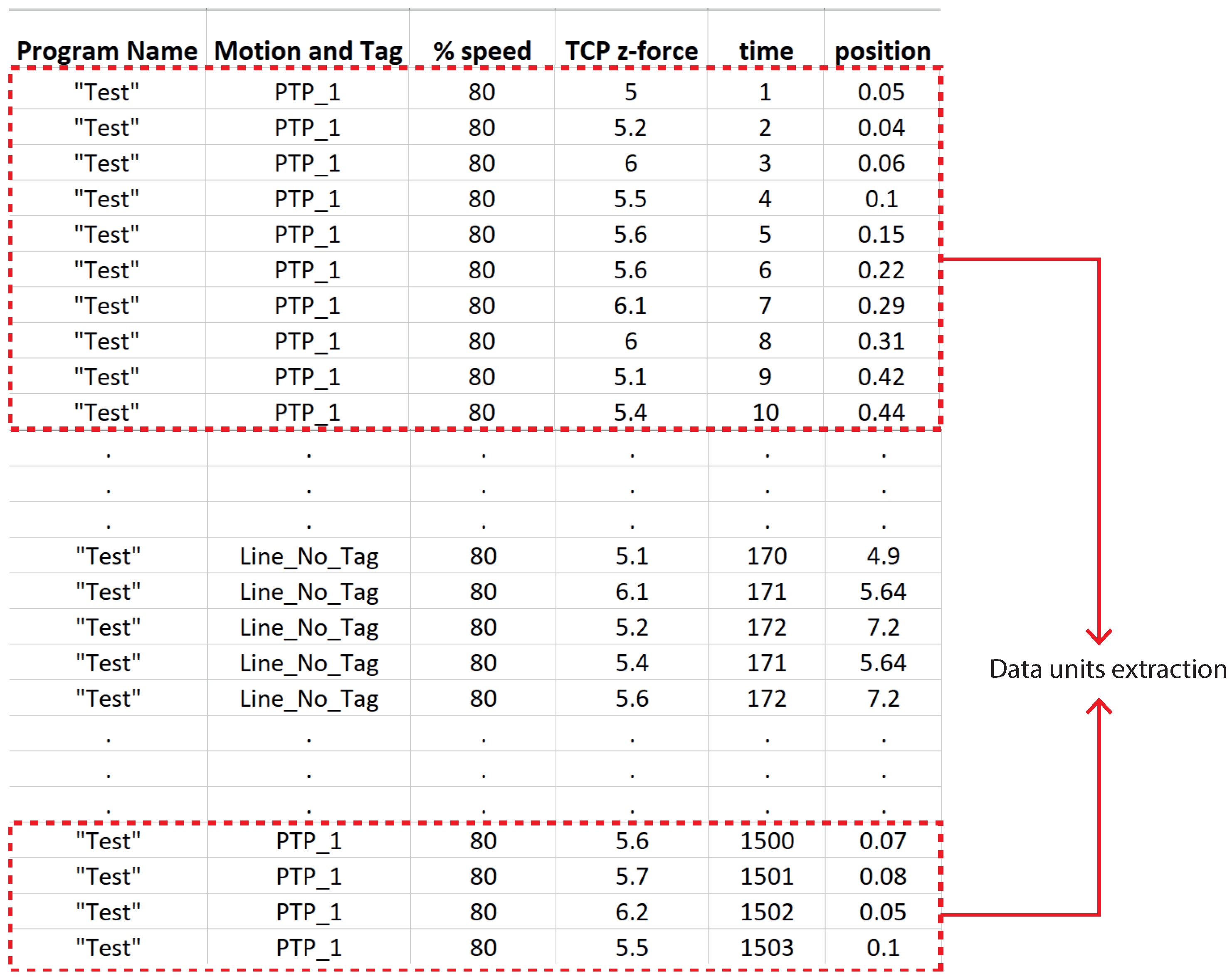
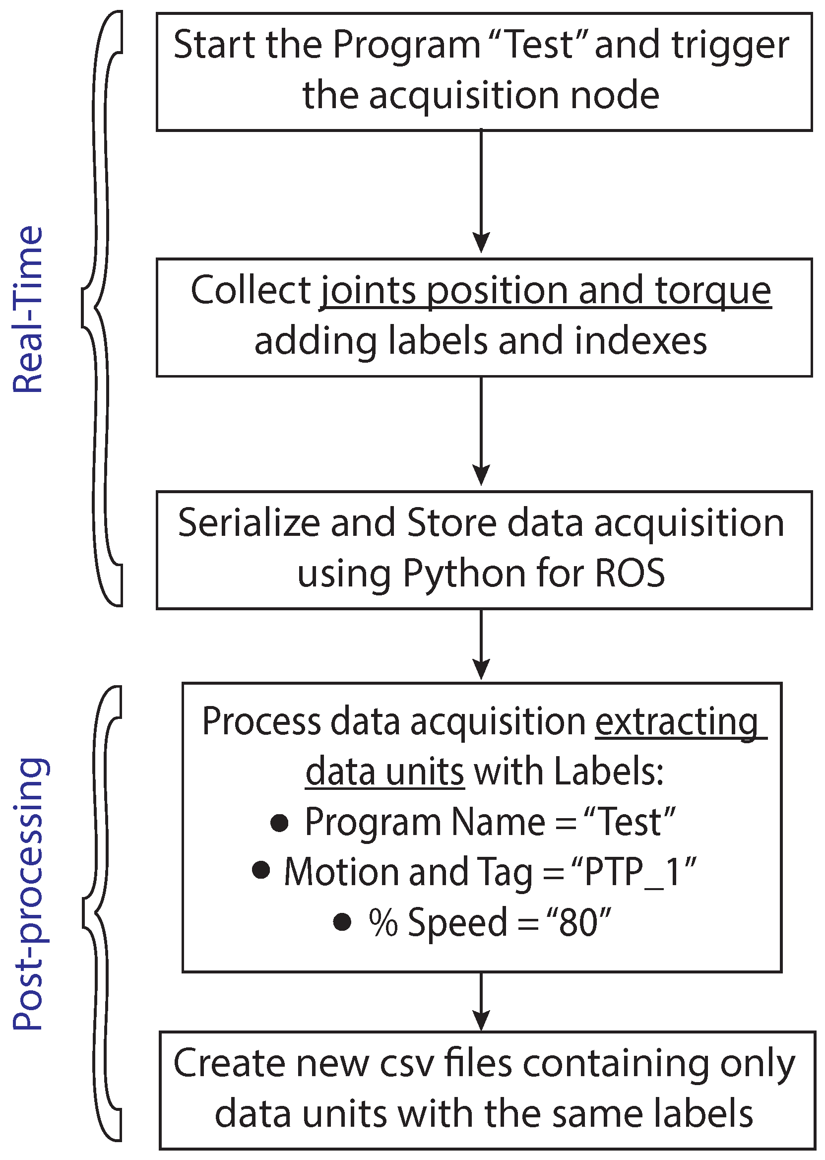
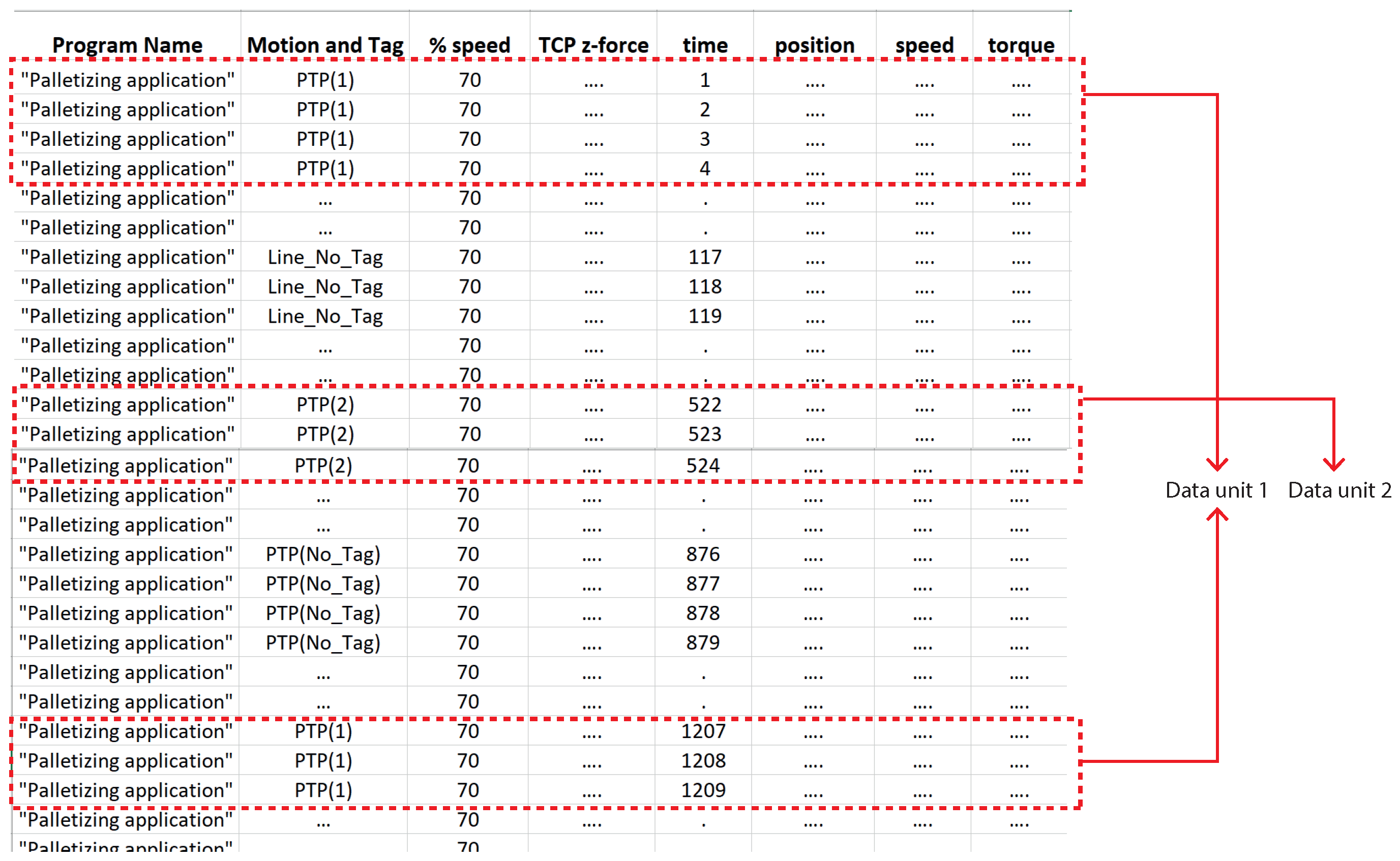
An example of data acquisition can be seen in Figure 4, where in the dash-dotted red line, units that belong to the same set are highlighted. This data acquisition example is referred to in the program “Test” introduced above (Section 3.2). The Flowchart describing the steps to manage the acquisition phase and extract data units during the program “Test” execution are shown in Figure 5.
Every label has been chosen for a precise reason: the “Program name” label is used to classify acquisitions based on the running program (as such, when the robot is performing a different program, we know to which program the acquisition belongs). The label “Motion and Tag” is only used to extract some specific data units acquired under certain a priori chosen conditions. The label “Percentual Speed” is also used to organize data units since the same motion executed at a different speeds leads to different data values and should not be analyzed together. Finally, the estimation of the TCP force along the z axis is a measurement used to understand whether the data units extracted were acquired under a certain load condition (the force estimation is sufficiently precise to understand whether the load on the TCP is constant or not). For further details regarding the use of the TCP force along the z axis, we refer the reader to the case study in Section 4.
4. Applying the CM Framework to a Case Study
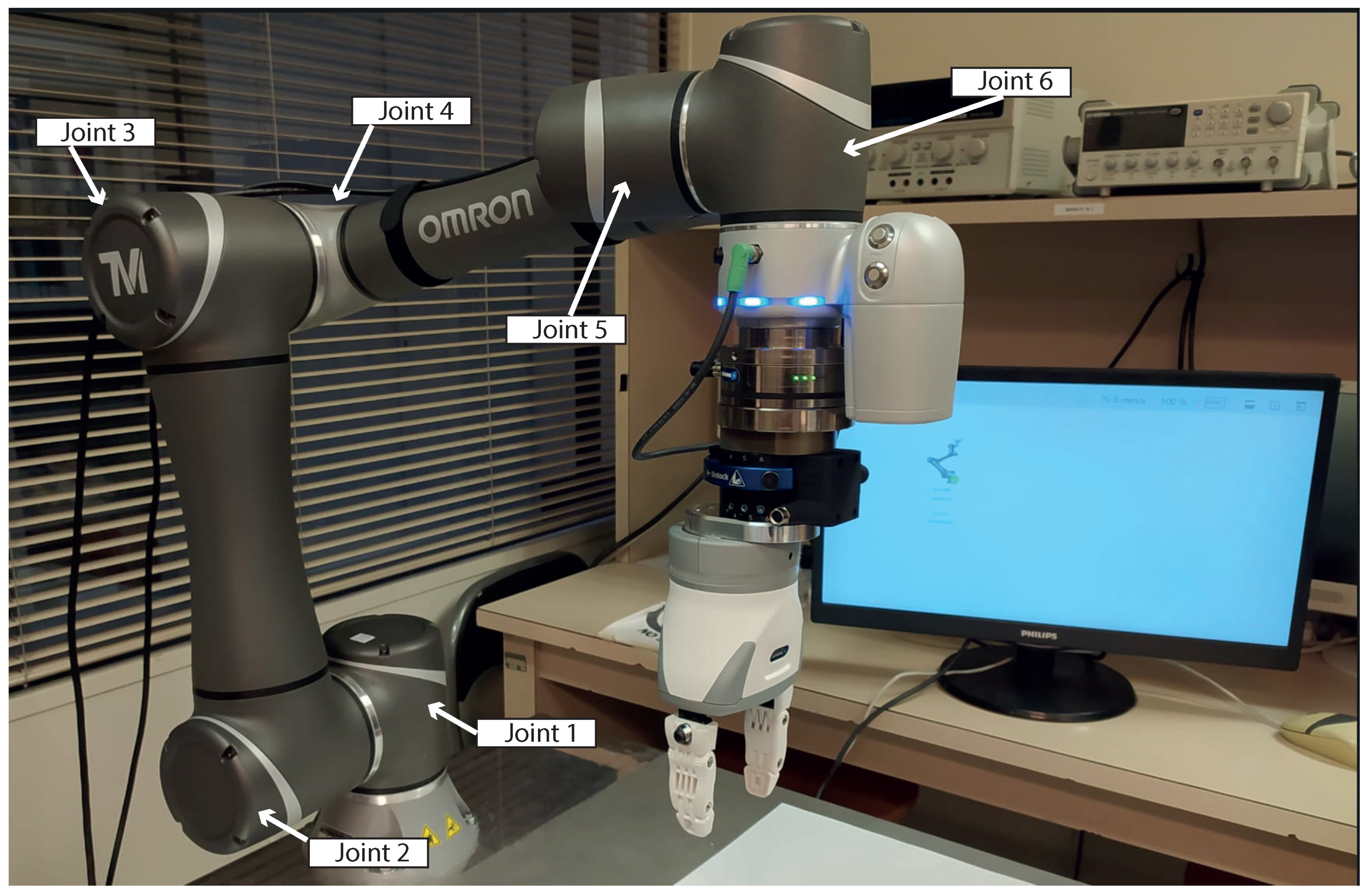
The CM framework presented above in this section was adapted to a case study using the Omron TM5-900 cobot, manufactured by Techman Robot Inc. Taiwan, and marketed by Omron Corp., Kyoto, Japan (Figure 6). Cobot specification is listed in Table 1. The motion commands to the cobot can be sent using a Programmable Logic Controller (PLC) or through the Python API motion library available in the Omron TM robots ROS package [3]. Giving too much detailed information regarding how to define motion commands using ROS and a trajectory planners library is out of the scope of this work; however, detailed information can be found in the GitHub read me file regarding the usage of our repository.
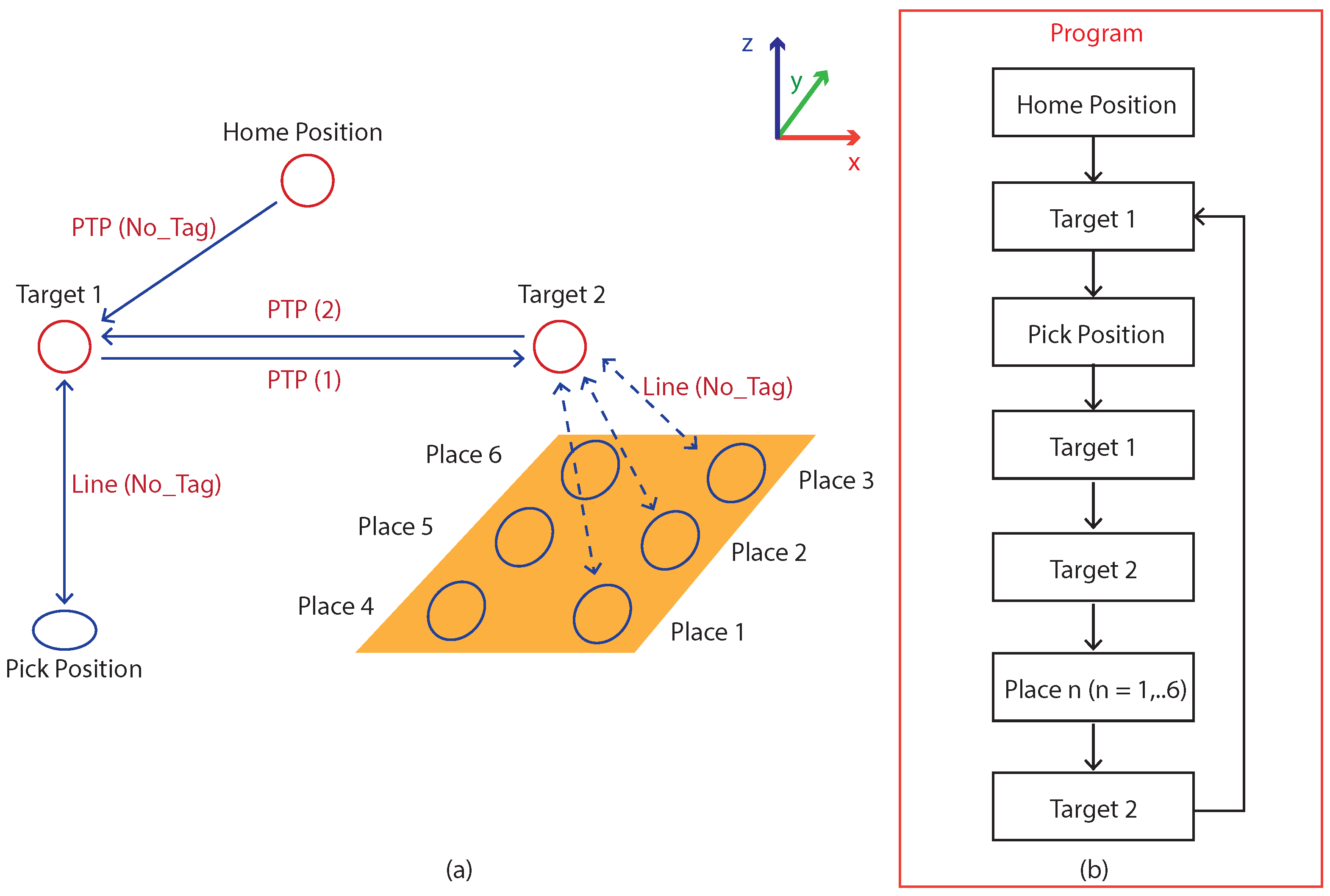
As a case study, we proposed to test the presented CM architecture in a palletizing application scenario using the Omron TM5-900 cobot. The program running on the cobot is a working cycle that comprises different motion commands to send the cobot to pick objects in a certain location and place them by filling a hypothetical pallet (in Figure 7, it is possible to see a schematic view of this application). In this program, the cobot starts from a home position and reaches a “Target1” position. Then, it goes down vertically (TCP z axis) to grab the object and up to the previous position. From “Target1”, the cobot moves to a second target position “Target2” and places the object in a certain pallet location repeating the sequence to build the pallet with a certain number of objects defined by the user. This application can be considered quite a standard in industrial scenarios and is interesting to study since we have different motion commands, positions, and load conditions that require defining a precise strategy to automatically detect faults in the data. The only assumption used under the testing phase is to palletize objects of approximately the same weight, picked every time in the same position.
The robot states that we collect to monitor cobot conditions are the following, proceeded by the labels defined in Section 3.3:
- Joint torques;
- Joint positions;
- Joint speeds.
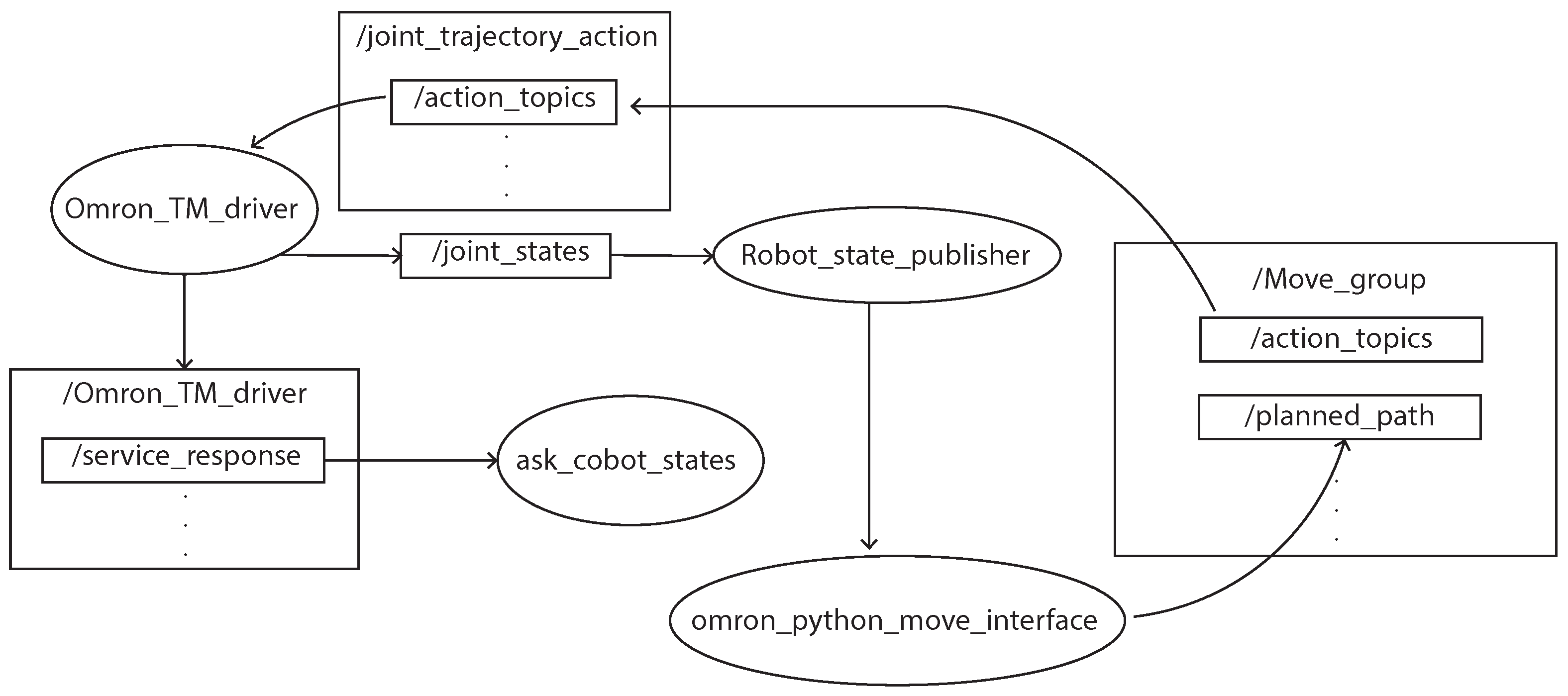
The joint positions and speeds are collected to check whether the joint movements are correct, while the joint torques are used to monitor the system conditions. Using the proposed ROS-based CM architecture, we send motion commands to execute the program while collecting controller data to monitor cobot states. Figure 8 shows a simplification of the whole interaction between ROS nodes. The graph algebra used is based on the rqt tool which is helpful to obtain a visual representation of the ROS nodes’ interactions. The nodes are circled, while inside the rectangle is specified on the top the nodes name with relative topics or services. In this schematic figure, not all the nodes running are shown, as indeed the secondary nodes are omitted because these are not relevant to understanding the application. However, using the function on the terminal “” (while the entire program is running), it is possible to visualize the representation of the entire connections.
The “Omron TM driver” node is the one responsible for managing the communication between the controller and the Linux system in which the ROS master is running (a schematic view of the connection was represented in Figure 1). The node “ask cobot state” is subscribed to the services (robot states that we want to monitor) published by the node “Omron TM driver” which directly access to the controller data and holds the communication (Figure 8). Inside the “ask cobot states” node, modules and libraries that implement the CM monitoring strategy discussed above are used. For instance, the Omron TM Python module creates an interface to send commands to the cobot such as the function, which is used for monitoring the current motion tag and sending a true value once the goal for a specific trajectory is reached (this function is used for indexing the label “Motion and Tag”). Otherwise, the pickle module implements binary protocols for serializing and de-serializing a Python object structure (which is used to collect all the data) or the rospy library (Python client library for ROS) to manage the acquisition and hold a certain communication rate. The “ask cobot state” node is executed continuously while the nodes “Omron Python move interface” and “move group” are responsible for the motions command and the program workflow. In particular, the “Omron python move interface” node implements all the logic sending motion commands and checking the correct execution of the program. The “move group” node manages all the information regarding the planned path and the “action” topics that are sent to the robot controller.
4.1. Definition of Data Analysis Methodology
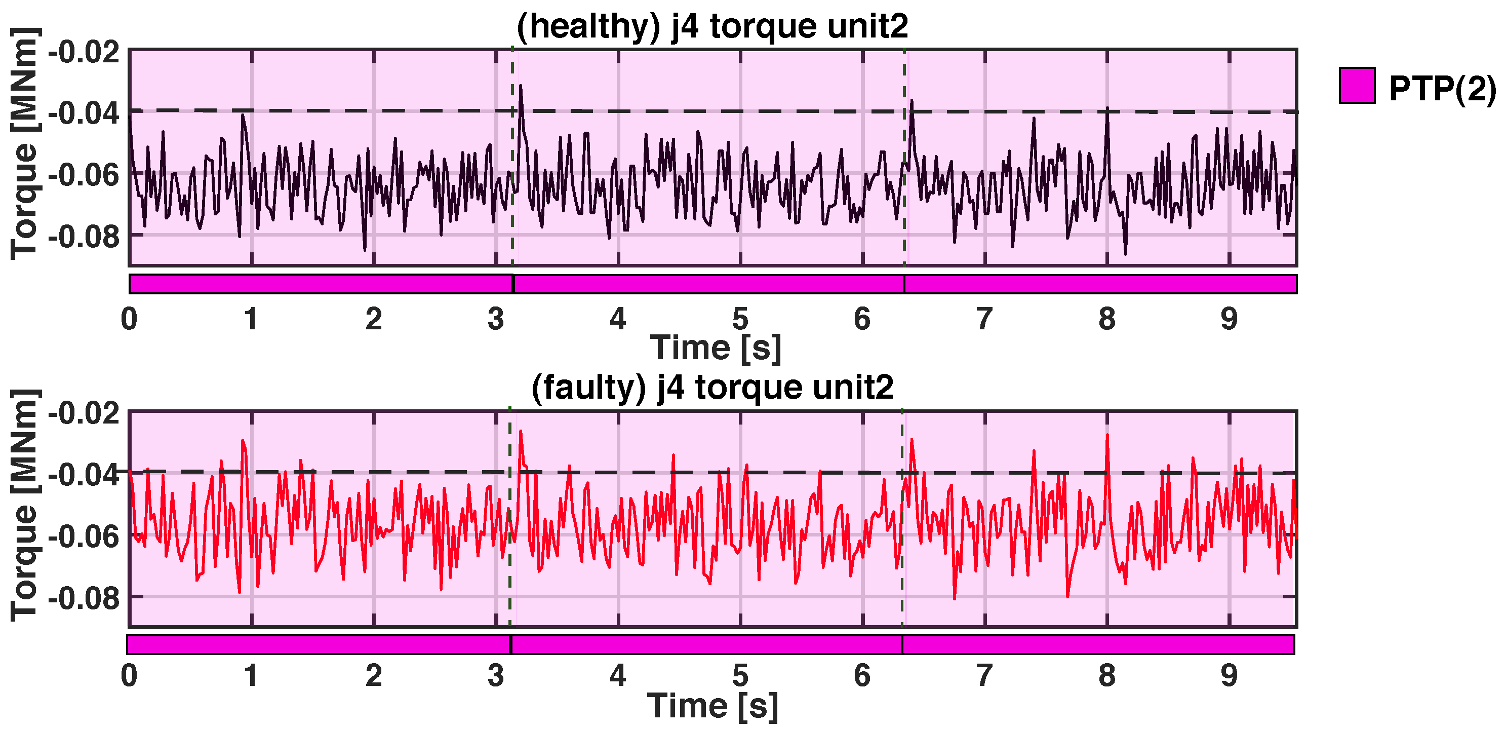
Analyzing this application, two instants have been selected for data units extraction: during the execution of the motion command PTP(1) where the cobot moves from “Target1” to “Target2” (Figure 7) carrying the object in order to place it and during the motion PTP(2) from “Target2” to “Target1” where the cobot is moving without any load. Therefore, once an acquisition has been performed, we automatically extract units that belong to these two working conditions before applying any kind of analysis. There are different reasons to choose to extract data under these working conditions in a palletizing application. Firstly, the movements that bring the cobot from “Target1” to “Target2” and vice versa are the most repeated in the program. Secondly, the start and end positions of the movements are always the same (the cobot must reach the “Target1” before picking and the “Target2” before placing, and there is no blending into those motions). Moreover, all the joints are involved in these motions to bring the cobot from start to end positions, and thus we have complete dynamic data for each joint. Finally, during the execution of PTP(1), we evaluate the cobot performance while carrying the load and in PTP(2) without it, whilst also taking into account load influence. Therefore, from every data acquisition, we extract units (using labels and indexes) that belong to these two selected sets. Data units are then collected and separately analyzed to define health indicators (HIs) useful for the automatic detection of malfunctions in the joints.
4.2. Results
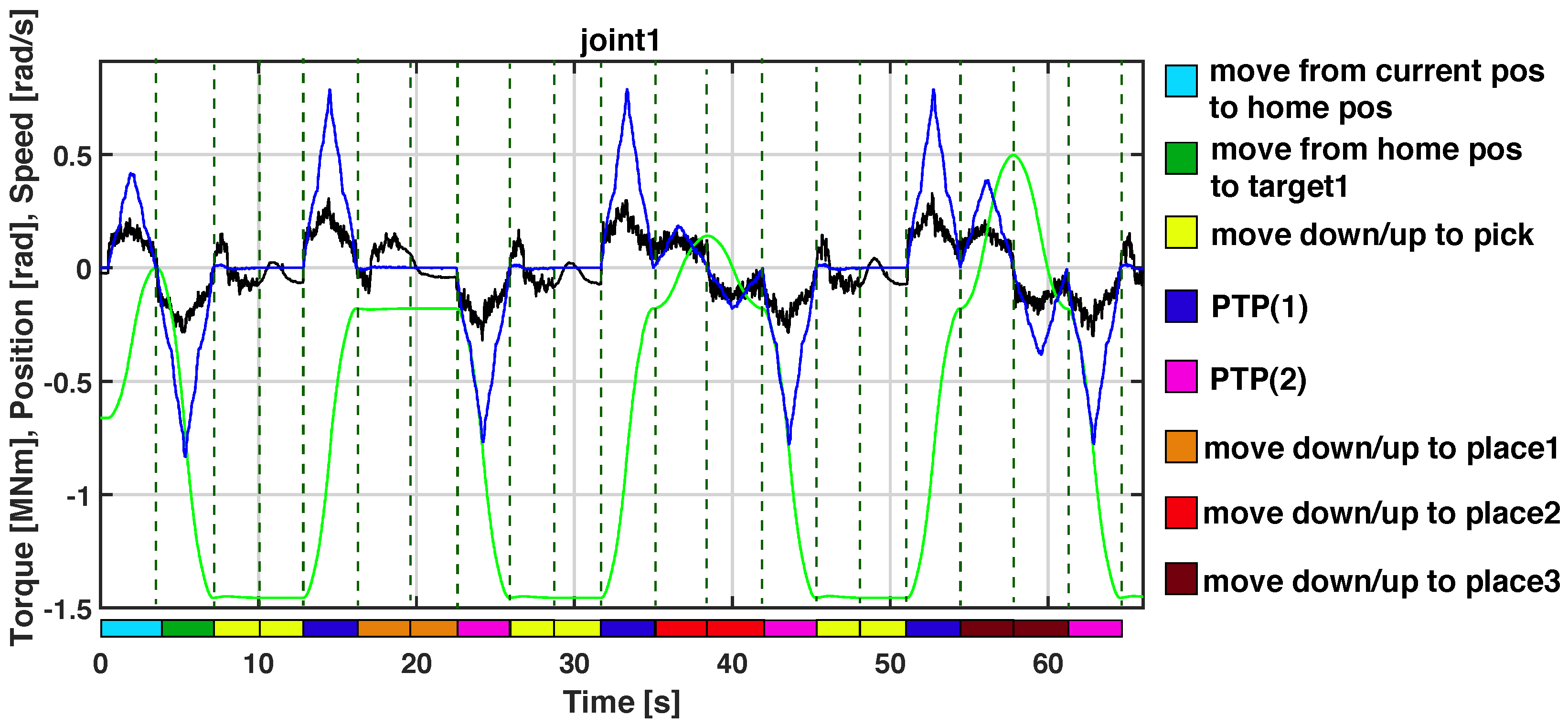
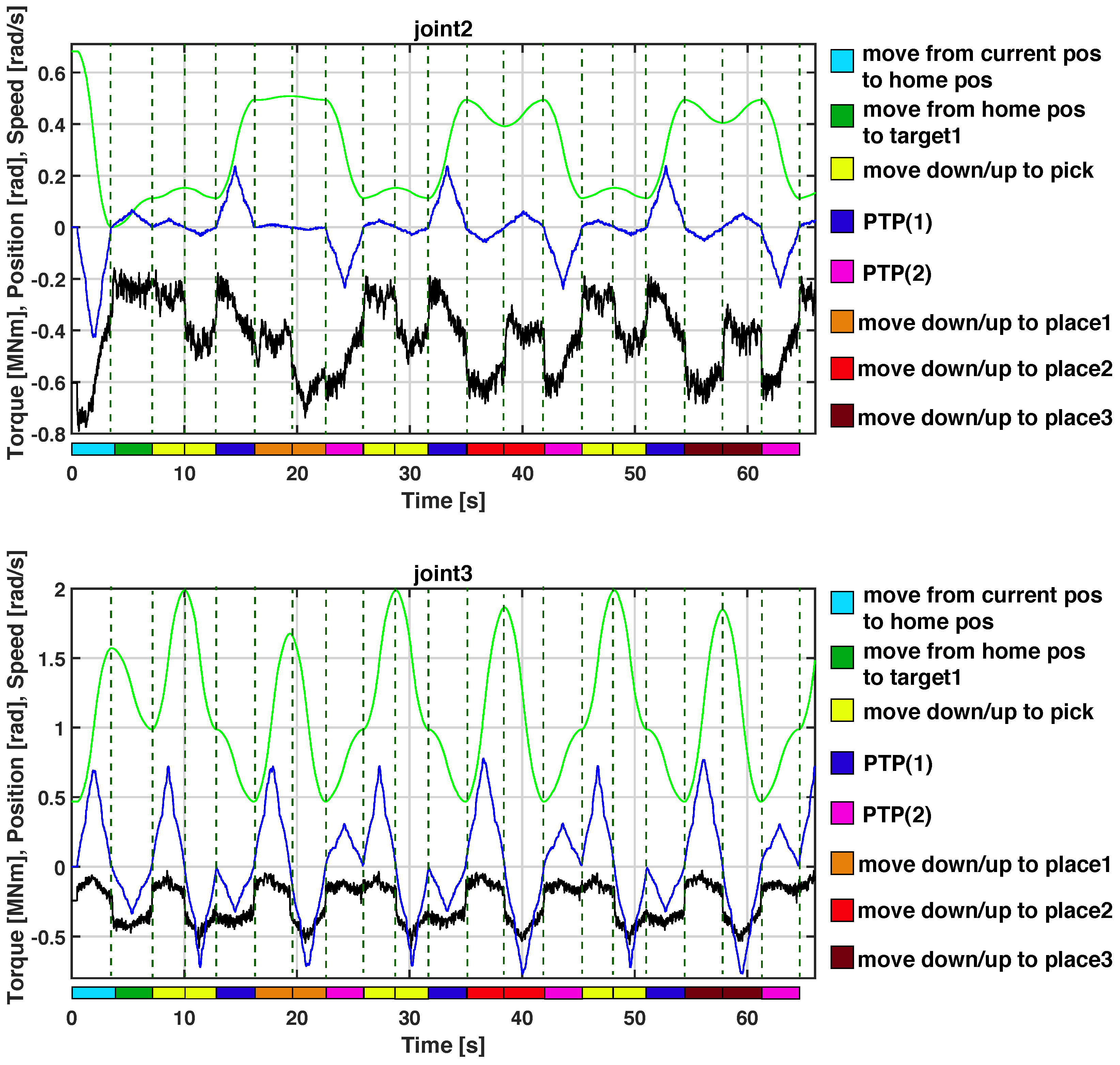
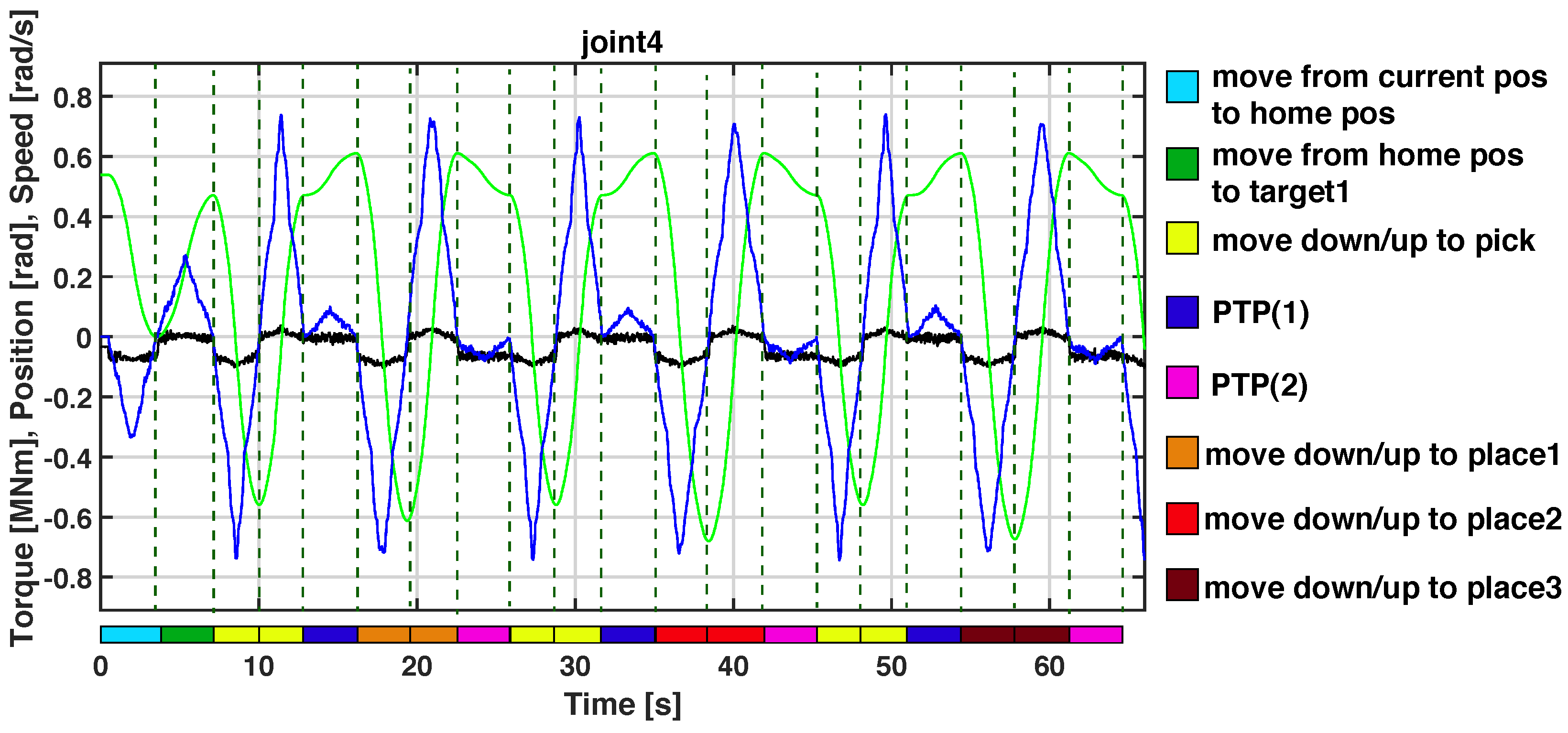
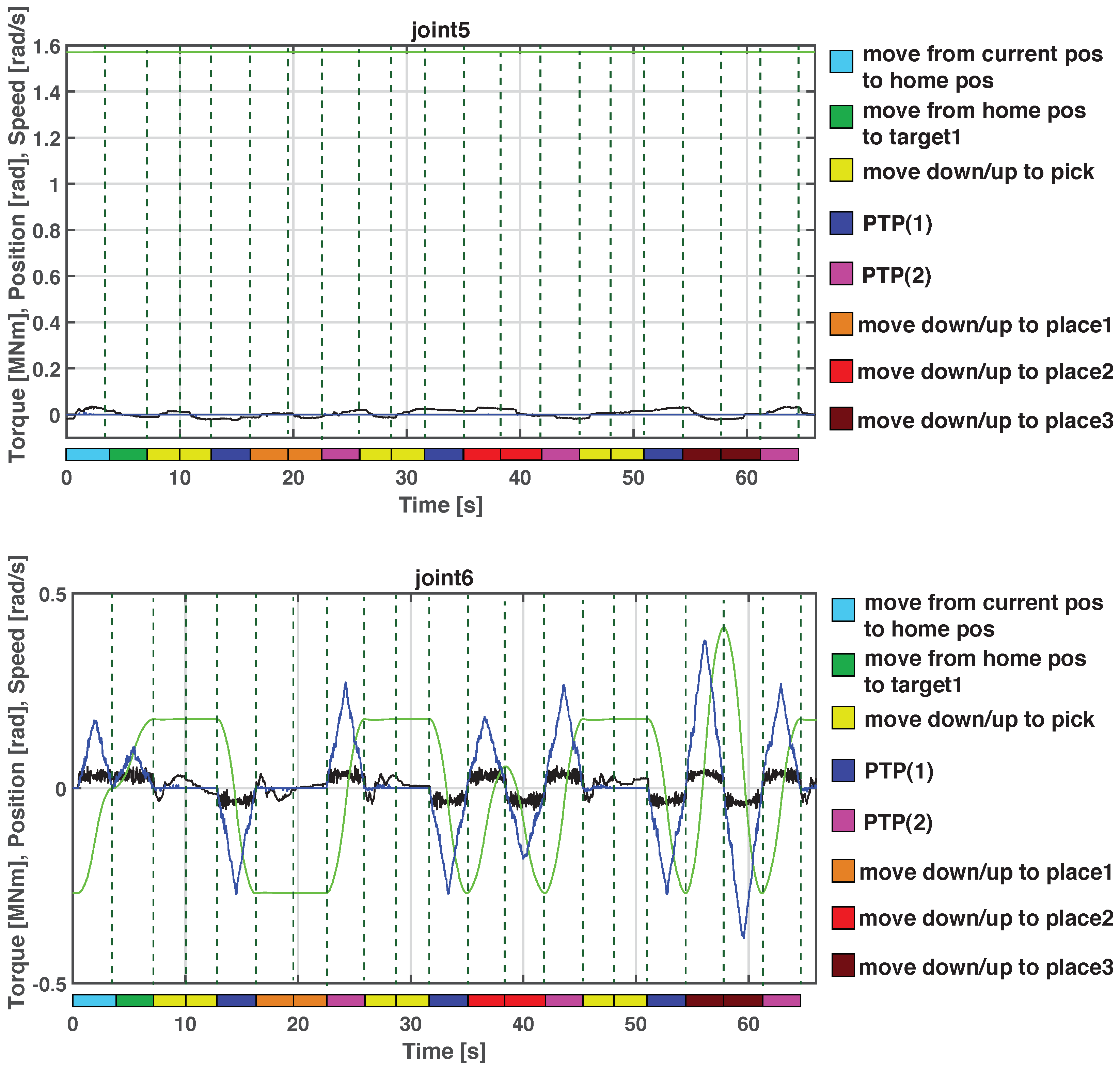
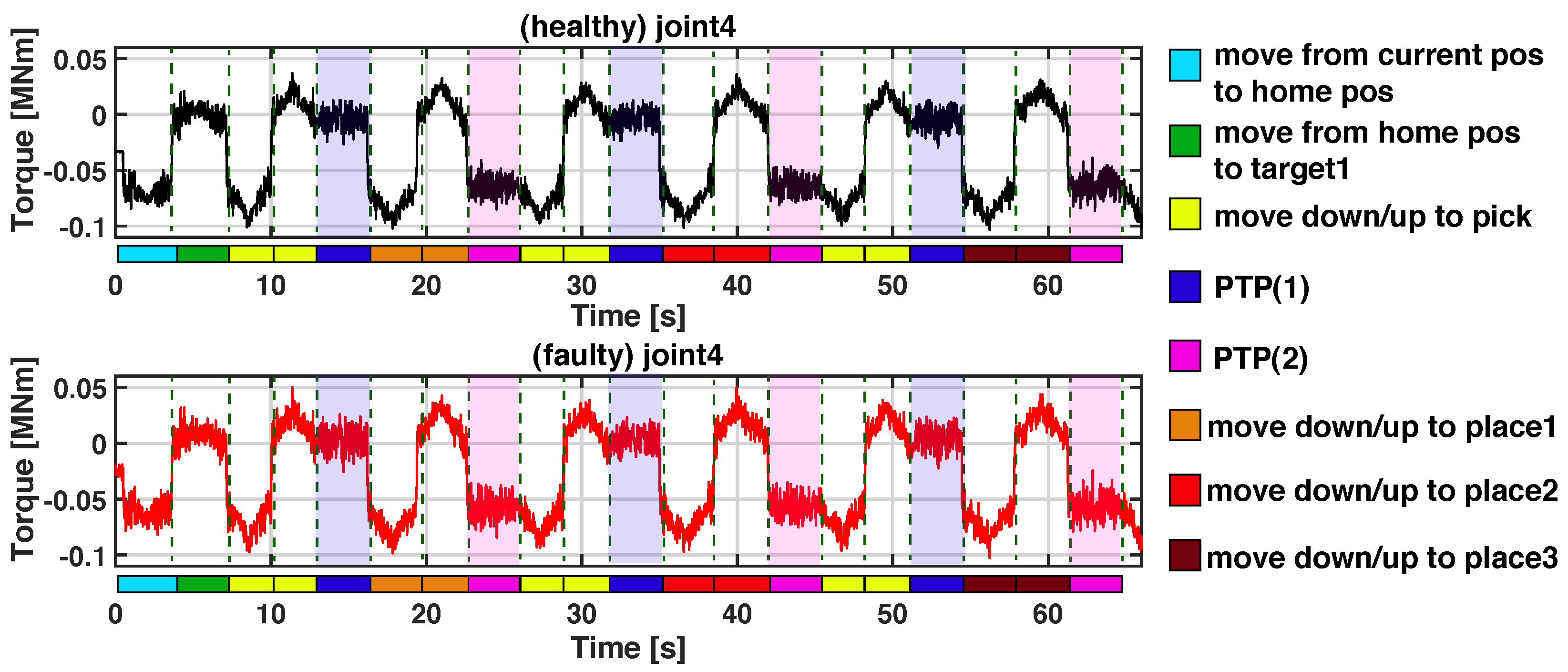
In this part, the results obtained using the proposed CM architecture with the Omron TM5-900 collaborative robot are discussed. Figure 9 and Figure 10 show an example of acquisition performed at 40 Hz sample frequency for 2750 samples (68.75 s for each acquisition). The palletizing program was executed at 70% of maximum speed. Figure 9 displays the joint torque (in black), position (in green) and speed (in blue) of the first three joints acquired while the cobot is executing the palletizing program, while Figure 10 displays the joint torque (in black), position (in green), and speed (in blue) of the last three cobot joints. It is possible to notice that only the fifth joint is not directly involved in any motions of this program. The torque contribution for this joint is only related to maintaining the current position during the program execution. In the bottom part of every graph, it is possible to see colors that refer to the motion command that was executed during the data acquisition while in the upper right corner the respective legend for each color. From every acquisition, we extract data units of joints torque, speed, and position with labels:
- Program Name = “Palletizing application”;
- Motion and Tag = PTP(1) and PTP(2);
- % speed = 70.
For completeness, a schematic view of the data unit extraction process can be seen in Figure 11. The extraction was done using a Python script that reads binaries’ acquisition files and creates text files only containing data units with the labels values defined above. This data extraction process is performed automatically once which cobot states and under which working conditions we want to perform the analyze have been a priori defined.
Automatic Detection of a Joint Malfunction
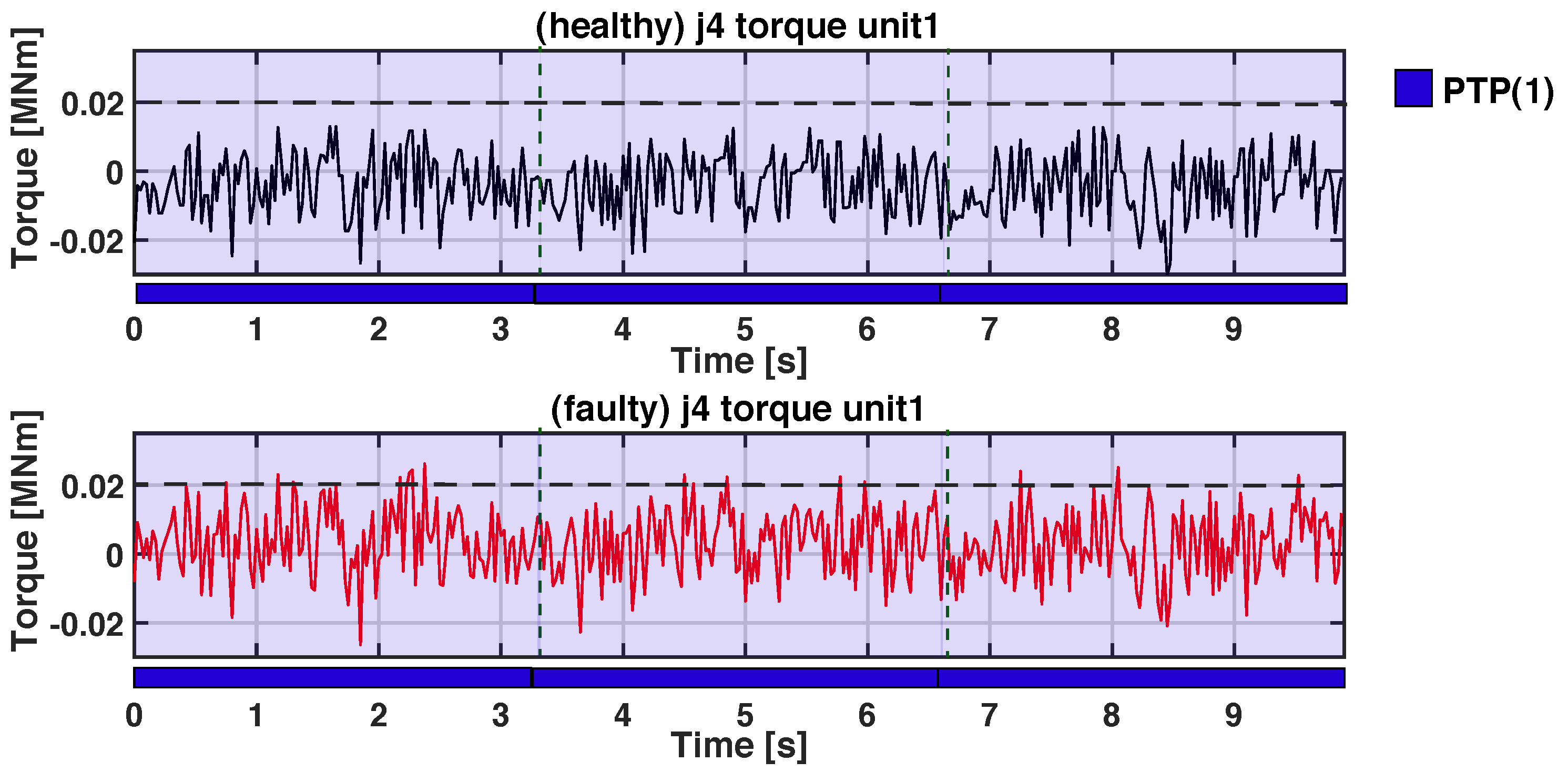
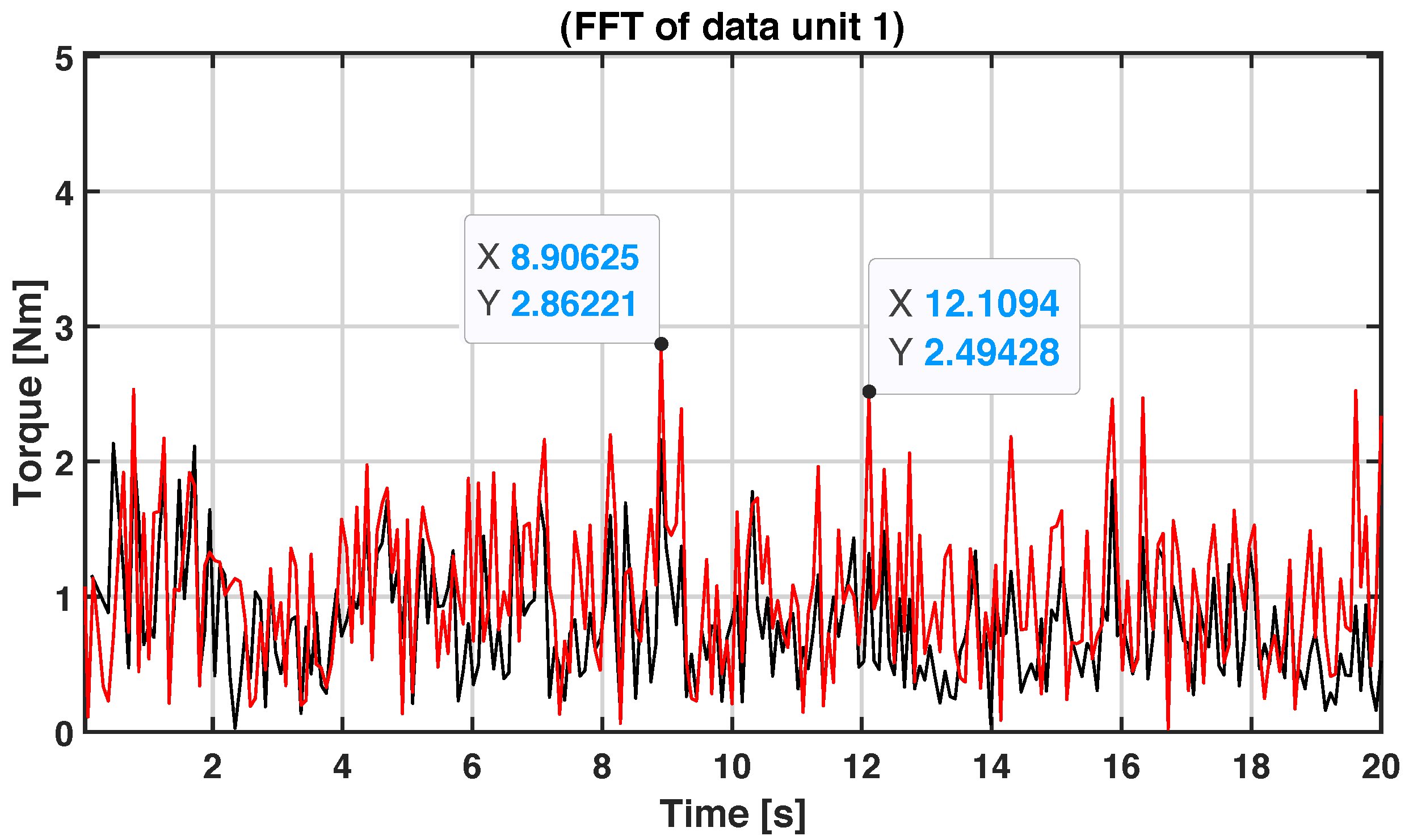
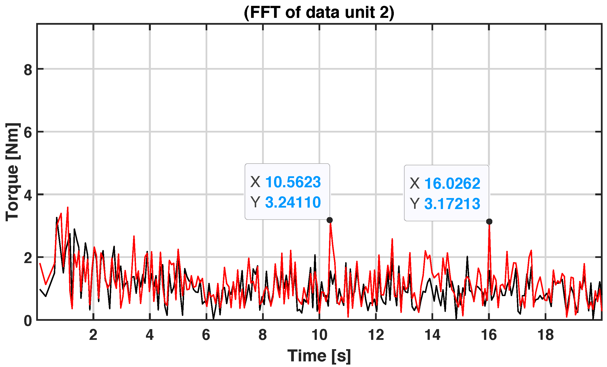
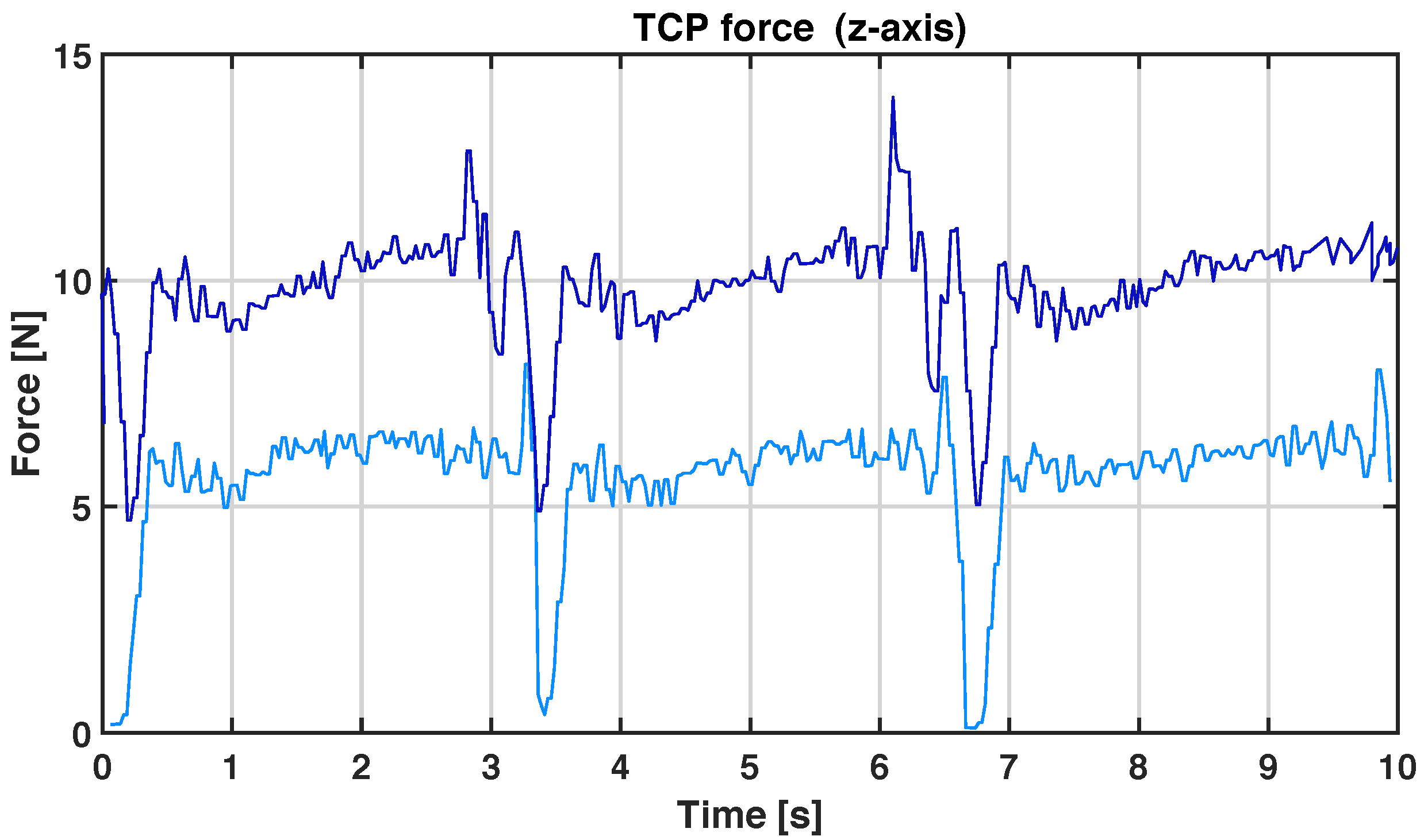
A malfunction was simulated on the fourth joint torque data by recreating a possible faulty behavior to show the effectiveness of our proposed approach. It was decided that a local fault would be simulated since its identification is highly relevant for the use of the robot itself considering the global behavior, because even a fault in a single mechanism can affect the entire planning, repeatability, and accuracy of the tasks. The fourth joint has been chosen since it is involved in all the movements of the palletizing program and to prove the effectiveness of the proposed method under a highly dynamic context. As introduced in a related work in Section, some papers use torque information to detect joint malfunction, which for this reason, the fault has been simulated on torque data. Moreover, as experienced in [12], where the torque signal has been studied to perform fault root cause analysis, when a malfunction in the mechanism of the joint arises, there is a homogeneous increment in the torque, i.e., the torque increases in the whole trajectory and not only in specific movements or positions under a fault. This is because mechanical deterioration creates friction in the joint mechanism affecting the entire movement of the joint. Therefore, a homogeneous and random distributed increment of 10% has been added onto the fourth joint torque data to show differences in the detection using the proposed methodology in contrast with analyzing the entire raw torque signal. For this purpose, Figure 12 shows the entire acquisition of the fourth joint torque signal under healthy and faulty conditions during the execution of the palletizing program. Meanwhile, Figure 13 and Figure 14 show, respectively, the torque signal after using the proposed method for data unit extraction, during the execution of PTP(1) and PTP(2) moves. Every time the PTP(1) or PTP(2) commands are executed, data are extracted from the entire acquisition and collected together, as shown in Figure 13 and Figure 14, where three subsequential data extractions are performed on an acquisition of 2750 samples at 40 Hz. There are plenty of methodologies that can be used to analyze these data sequences extracted from the entire acquisition: in this part, we define three well-known HIs to monitor the system health. In particular, we evaluate the dominant frequencies peaks, the wavelet entropy, and the signal kurtosis. These three HIs have been chosen according to [10] where the most effective HIs were derived from several review papers regarding the CM gearbox and bearing CM [28,29]. However, the definition of the best methodology to analyze data is beyond the scope of this work, since in fact, the best methodology to choose depends on which kind of fault we want to identify. Our purpose is to suggest a general CM architecture that can be used in different situations with collaborative robots, and here we provide an example based on this case study. We show below Table 2 with HIs calculated on both data unit extractions and on Figure 15 and Figure 16, respectively, the Fast Fourier Transform (FFT) applied on the torque data unit sequences in the case of healthy and faulty behavior. Applying this methodology we can define basic HIs, generally used for fault detection only under stationary conditions, which would be ineffective if directly applied to the entire raw torque acquisition. This is because, as previously discussed, the torque varies according to the system motions (i.e., speed, load, positions, etc.), and it would thus be impossible select reference values to distinguish normal from abnormal behaviors. In contrast, using the proposed CM approach, it is possible to define HIs or rather more complex strategies to automatically detect malfunctions and monitor the health of the system. The analysis proposed is valid for any joint, giving equivalent results in terms of monitoring. The fourth joint was chosen since it is the most involved in all the movements of the palletizing program, but this does not preclude the choice of applying the same concepts to a different joint. Choosing another joint will lead to similar conclusions since all the joints are mechanically constructed with the same components. Potentially, the same analysis can be simultaneously performed on all the joints of the manipulator. Finally, since the torque signal is sensible to load variations, we must ensure that every data unit extraction has been performed under similar load conditions. For this purpose, as introduced above, we use the TCP z axis force estimation. The force is calculated using algorithms which, from joint torques, can estimate the force on the TCP [30], and is already available in the controller. Figure 17 shows the instantaneous estimated TCP force along the z axis related to data unit 1 extraction under the execution of PTP(1). In dark blue, the force estimation is performed when the robot is carrying a load of 1 kg, while in light blue, the force is performed when the robot executes the same motions but is unloaded. As it is now possible to notice in Figure 17, the estimated value is not really precise for control purposes (e.g., adaptive force control) but can be used to check whether the load conditions during a specific motion sequence are in the same range or not. To conclude, even if three basic HIs have been defined in this proof of concept (PoC), the data units extraction of the joint torque could be analyzed using other tools that provide good results, even under non-stationary conditions. For instance, in [24], the authors achieved accurate fault diagnosis using time–frequency signal analysis with the discrete wavelet transform and artificial neural network. Datta et al. suggested using the neural network and wavelet multi-resolution analysis for diagnosis in Industrial Robots [31], while in [32], the authors proposed a deep transferable motion-adaptive fault detection method that uses torque ripples for the fault detection of industrial robot gearboxes. All these more advanced techniques could be used in the post-processing phase after the collection of torque data units to automatically detect and diagnose failures. To summarize, with respect to prior arts, our work proposes a CM architecture with a strategy to extract comparable data units which can be valid for applications with a low degree of repeatability, where it is difficult to establish a methodology to analyze data since the manipulator executes different combinations of motions in a single program—such as in applications where the trajectory is planned dynamically. This solution can be used in combination with many different post-processing methodologies for fault detection, isolation and diagnosis already consolidated in the literature. Using this ROS-based CM architecture can speed up the analysis and validation steps by helping to test different approaches for FDD (Fault Detection and Diagnosis) in collaborative manipulators implementing all the algorithms to control robot motions, data acquisition and data analysis in the same framework. Moreover, compared to most similar work [26], our solution shows its effectiveness in a real-industrial scenario without the need to develop data models to track all the programmable motion anomalies for all the possible combinations of movements in a cobot application.
5. Conclusions
This document analyzes problems related to the application of an effective CM architecture and determining automatic fault detection algorithms in collaborative robots used in dynamic tasks. In particular, a solution has been provided to contribute to the definition of an open source CM architecture based on ROS which can be considered valid for manipulator’s applications with a low degree of repeatability, where it is difficult to establish a methodology to analyze data since the cobot executes different combinations of motions in a single program. Previous work in industrial or collaborative robot fault diagnostics has the limit of being built for specific motion sequences or programs and may not accurately or consistently detect faults in other motions due to motion discrepancies (different positions, speeds, loads, etc.). In contrast, this document presents a CM architecture with a relative strategy used to pre-process data helping for the definition of algorithms for the automatic detection of failures. The suggested approach is based on data labeling and indexing and aims to extract comparable data units to easily detect a possible failure in cobots. The end of this paper is provided with a proof of concept (PoC) where the proposed architecture was implemented and tested in a real application scenario using the Omron TM5-900 collaborative robot executing palletizing tasks. The results show that applying the proposed strategy enables the possibility of defining basic HIs that, on the contrary, would be ineffective if directly applied to monitoring the health of cobot joints.
Author Contributions
Conceptualization, G.N. and A.B.; methodology, G.N.; software, G.N.; validation, G.N. and A.B.; formal analysis, G.N. and A.B.; investigation, G.N. and A.B.; resources, G.N. and A.B.; data curation, G.N.; writing—original draft preparation, G.N.; writing—review and editing, G.N., S.L. and A.B.; visualization, G.N. and A.B.; supervision, S.L. and A.B.; project administration, A.B.; funding acquisition, A.B. All authors have read and agreed to the published version of the manuscript.
Funding
This research was funded by HD3Flab Project “Human Digital Flexible Factory of the Future Laboratory” EU ERDF (European Regional Development Fund), Regional Operative Plan (POR) MARCHE Region FESR (Fondo Europeo di Sviluppo Regionale) 2014/2020, AXIS 1, Specific Objective 2, ACTION 2.1.
Institutional Review Board Statement
Not applicable.
Informed Consent Statement
Not applicable.
Data Availability Statement
No new data were created or analyzed in this study. Data sharing is not applicable to this article.
Acknowledgments
A special thanks to the Robotics team of Omron Europe (Barcelona), which contributed with authors to the development, test, and validation of the Omron TM ROS package used in this paper.
Conflicts of Interest
The authors declare no conflict of interest.
References
- Inkulu, A.K.; Bahubalendruni, M.R.; Dara, A.; SankaranarayanaSamy, K. Challenges and opportunities in human robot collaboration context of Industry 4.0—A state of the art review. Ind. Robot Int. J. Robot. Res. Appl. 2021, 49, 226–239. [Google Scholar] [CrossRef]
- Eswaran, M.; Bahubalendruni, M.R. Challenges and opportunities on AR/VR technologies for manufacturing systems in the context of industry 4.0: A state of the art review. J. Manuf. Syst. 2022, 65, 260–278. [Google Scholar] [CrossRef]
- Nabissi, G. Omron TM Robots—ROS. 2022. Available online: https://github.com/GiakNab/Omron_TM_robots-ROS (accessed on 9 December 2022).
- Khalastchi, E.; Kalech, M. Fault detection and diagnosis in multi-robot systems: A survey. Sensors 2019, 19, 4019. [Google Scholar] [CrossRef] [PubMed] [Green Version]
- Visinsky, M.L.; Cavallaro, J.R.; Walker, I.D. Robotic fault detection and fault tolerance: A survey. Reliab. Eng. Syst. Saf. 1994, 46, 139–158. [Google Scholar] [CrossRef] [Green Version]
- Alobaidy, M.A.A.; Abdul-Jabbar, J.M.; Al-khayyt, S.Z. Faults Diagnosis in Robot Systems: A Review. Al-Rafidain Eng. J. 2020, 25, 164–175. [Google Scholar] [CrossRef]
- Jaber, A.A.; Bicker, R. Development of a Condition Monitoring Algorithm for Industrial Robots based on Artificial Intelligence and Signal Processing Techniques. Int. J. Electr. Comput. Eng. 2018, 8, 996–1009. [Google Scholar] [CrossRef] [Green Version]
- Xu, K.; Wu, X.; Wang, D.; Liu, X. Electromechanical coupling modeling and motor current signature analysis of bolt loosening of industrial robot joint. Mech. Syst. Signal Process. 2023, 184, 109681. [Google Scholar] [CrossRef]
- Raouf, I.; Lee, H.; Kim, H.S. Mechanical fault detection based on machine learning for robotic RV reducer using electrical current signature analysis: A data-driven approach. J. Comput. Des. Eng. 2022, 9, 417–433. [Google Scholar] [CrossRef]
- Nentwich, C.; Reinhart, G. A Method for Health Indicator Evaluation for Condition Monitoring of Industrial Robot Gears. Robotics 2021, 10, 80. [Google Scholar] [CrossRef]
- Graabæk, S.G.; Ancker, E.V.; Christensen, A.L.; Fugl, A.R. An Experimental Comparison of Anomaly Detection Methods for Collaborative Robot Manipulators. IEEE Trans. Autom. Sci. Eng. 2022, 1, 1–14. [Google Scholar] [CrossRef]
- Izagirre, U.; Andonegui, I.; Egea, A.; Zurutuza, U. A methodology and experimental implementation for industrial robot health assessment via torque signature analysis. Appl. Sci. 2020, 10, 7883. [Google Scholar] [CrossRef]
- Cheng, F.; Raghavan, A.; Jung, D.; Sasaki, Y.; Tajika, Y. High-Accuracy Unsupervised Fault Detection of Industrial Robots Using Current Signal Analysis. In Proceedings of the 2019 IEEE International Conference on Prognostics and Health Management (ICPHM), San Francisco, CA, USA, 17–20 June 2019; pp. 1–8. [Google Scholar] [CrossRef]
- Vallachira, S.; Orkisz, M.; Norrlöf, M.; Butail, S. Data-driven gearbox failure detection in industrial robots. IEEE Trans. Ind. Inform. 2019, 16, 193–201. [Google Scholar] [CrossRef]
- Ohno, M.; Takeda, Y. Design of target trajectories for the detection of joint clearances in parallel robot based on the actuation torque measurement. Mech. Mach. Theory 2021, 155, 104081. [Google Scholar] [CrossRef]
- Bonci, A.; Kermenov, R.; Longhi, S.; Nabissi, G. Motor Torque Analysis for diagnosis in PMSMs under non-stationary conditions. In Proceedings of the 2021 26th IEEE International Conference on Emerging Technologies and Factory Automation (ETFA), Vasteras, Sweden, 7–10 September 2021; pp. 1–6. [Google Scholar]
- Bonci, A.; Indri, M.; Kermenov, R.; Longhi, S.; Nabissi, G. Comparison of PMSMs Motor Current Signature Analysis and Motor Torque Analysis Under Transient Conditions. In Proceedings of the 2021 IEEE 19th International Conference on Industrial Informatics (INDIN), Palma de Mallorca, Spain, 21–23 July 2021; pp. 1–6. [Google Scholar]
- Han, Z.Y.; Liu, Y.L.; Jin, H.Y.; Fu, H.Y. A review of methodologies used for fault diagnosis of gearbox. Appl. Mech. Mater. 2013, 415, 510–514. [Google Scholar] [CrossRef]
- Peshkin, M.; Colgate, J.E. Cobots. Ind. Robot Int. J. 1999, 26, 335–341. [Google Scholar] [CrossRef]
- Vicentini, F. Collaborative robotics: A survey. J. Mech. Des. 2021, 143, 040802. [Google Scholar] [CrossRef]
- Bonci, A.; Cen Cheng, P.D.; Indri, M.; Nabissi, G.; Sibona, F. Human–robot perception in industrial environments: A survey. Sensors 2021, 21, 1571. [Google Scholar] [CrossRef]
- Bittencourt, A.C.; Saarinen, K.; Sander-Tavallaey, S.; Gunnarsson, S.; Norrlöf, M. A data-driven approach to diagnostics of repetitive processes in the distribution domain–applications to gearbox diagnostics in industrial robots and rotating machines. Mechatronics 2014, 24, 1032–1041. [Google Scholar] [CrossRef] [Green Version]
- Huan-Kun, H.; Hsiang-Yuan, T.; Huang, M.B.; Huang, H.P. Intelligent Fault Detection, Diagnosis and Health Evaluation for Industrial Robots. Mechanics 2021, 27, 70–79. [Google Scholar]
- Jaber, A.A.; Bicker, R. Fault diagnosis of industrial robot gears based on discrete wavelet transform and artificial neural network. Insight-Non Test. Cond. Monit. 2016, 58, 179–186. [Google Scholar] [CrossRef]
- Bonci, A.; Longhi, S.; Nabissi, G.; Verdini, F. Predictive Maintenance System using motor current signal analysis for Industrial Robot. In Proceedings of the 2019 24th IEEE International Conference on Emerging Technologies and Factory Automation (ETFA), Zaragoza, Spain, 10–13 September 2019; pp. 1453–1456. [Google Scholar]
- Park, Y.S.; Yoo, D.Y.; Lee, J.W. Programmable Motion-Fault Detection for a Collaborative Robot. IEEE Access 2021, 9, 133123–133142. [Google Scholar] [CrossRef]
- Blodt, M.; Chabert, M.; Regnier, J.; Faucher, J. Mechanical load fault detection in induction motors by stator current time-frequency analysis. IEEE Trans. Ind. Appl. 2006, 42, 1454–1463. [Google Scholar] [CrossRef]
- Caesarendra, W.; Tjahjowidodo, T. A review of feature extraction methods in vibration-based condition monitoring and its application for degradation trend estimation of low-speed slew bearing. Machines 2017, 5, 21. [Google Scholar] [CrossRef]
- Zhu, J.; Nostrand, T.; Spiegel, C.; Morton, B. Survey of condition indicators for condition monitoring systems. In Proceedings of the Annual Conference of the PHM Society, Fort Worth, TX, USA, 29 September–2 October 2014; Volume 6. [Google Scholar]
- Phong, L.D.; Choi, J.; Kang, S. External force estimation using joint torque sensors for a robot manipulator. In Proceedings of the 2012 IEEE International Conference on Robotics and Automation, Saint Paul, MN, USA, 14–18 May 2012; pp. 4507–4512. [Google Scholar]
- Datta, A.; Mavroidis, C.; Krishnasamy, J.; Hosek, M. Neural netowrk based fault diagnostics of industrial robots using wavelt multi-resolution analysis. In Proceedings of the 2007 American Control Conference, New York, NY, USA, 9–13 July 2007; pp. 1858–1863. [Google Scholar]
- Oh, Y.; Kim, Y.; Na, K.; Youn, B.D. A deep transferable motion-adaptive fault detection method for industrial robots using a residual–convolutional neural network. ISA Trans. 2022, 128, 521–534. [Google Scholar] [CrossRef]
Figure 1.
Connection schematic view.

Figure 2.
Example of a single joint n position acquisition during the execution of the “Test” program. The colors below the graph’s x axis represent the motion commands executed during the acquisition.
Figure 2.
Example of a single joint n position acquisition during the execution of the “Test” program. The colors below the graph’s x axis represent the motion commands executed during the acquisition.

Figure 3.
Example of a single joint n position and torque acquisition during the execution of the “Test” program. The colors below the graph’s x axis represent the motion commands executed during the acquisition.
Figure 3.
Example of a single joint n position and torque acquisition during the execution of the “Test” program. The colors below the graph’s x axis represent the motion commands executed during the acquisition.

Figure 4.
Example of data unit extraction referred to the program “Test” introduced in Section 3.3.
Figure 4.
Example of data unit extraction referred to the program “Test” introduced in Section 3.3.

Figure 5.
Flowchart representing the steps to extract data units during program execution.

Figure 6.
Image of the Omron TM5-900 collaborative robot used for the case study.

Figure 7.
Schematic view of a basic palletizing application with the relative coordinating system on the top right of image (a). Image (b) shows the program workflow executed.
Figure 7.
Schematic view of a basic palletizing application with the relative coordinating system on the top right of image (a). Image (b) shows the program workflow executed.

Figure 8.
Schematic view representing the interaction between the principal ROS nodes involved in the proposed application. The nodes are circled, while inside the squares are specified on the top of the nodes’ names with relative topics or services.
Figure 8.
Schematic view representing the interaction between the principal ROS nodes involved in the proposed application. The nodes are circled, while inside the squares are specified on the top of the nodes’ names with relative topics or services.

Figure 9.
First, second, and third joints’ torque (in black), speed (in blue), and position (in green) acquired at 40 Hz for the 68.75 section (2750 samples each) during the execution of the palletizing program. The colors below the graph’s x axis represent the motion commands executed during the acquisition.


Figure 10.
Fourth, fifth, and sixth joints’ torque (in black), speed (in blue), and position (in green) acquired at 40 Hz for the 68.75 section (2750 samples each) during the execution of the palletizing program. The colors below the graph’s x axis represent the motion commands executed during the acquisition.


Figure 11.
Image representing the data unit extraction applied during the execution of the palletizing program.
Figure 11.
Image representing the data unit extraction applied during the execution of the palletizing program.

Figure 12.
Fourth joint torque acquisition in the case of healthy (in black, above) and faulty (in red, below).
Figure 12.
Fourth joint torque acquisition in the case of healthy (in black, above) and faulty (in red, below).

Figure 13.
Data unit 1 extraction. In this Figure, three subsequential joint torque units are represented which were extracted with the label “PTP(1)” from the acquisition of 2750 sample at 40 Hz. In black and in red, respectively, the 4th joint torque is under healthy and faulty conditions.
Figure 13.
Data unit 1 extraction. In this Figure, three subsequential joint torque units are represented which were extracted with the label “PTP(1)” from the acquisition of 2750 sample at 40 Hz. In black and in red, respectively, the 4th joint torque is under healthy and faulty conditions.

Figure 14.
Data units 2 extraction. In this Figure, three subsequential joint torque units are represented which were extracted with the label “PTP(2)” from the acquisition of 2750 sample at 40 Hz. In black and in red, respectively, the 4th joint torque is under healthy and faulty conditions.
Figure 14.
Data units 2 extraction. In this Figure, three subsequential joint torque units are represented which were extracted with the label “PTP(2)” from the acquisition of 2750 sample at 40 Hz. In black and in red, respectively, the 4th joint torque is under healthy and faulty conditions.

Figure 15.
FFT applied to data unit 1 extraction. In black, the FFT of the joint torque under healthy conditions is represented, while in red, it is under in faulty conditions.
Figure 15.
FFT applied to data unit 1 extraction. In black, the FFT of the joint torque under healthy conditions is represented, while in red, it is under in faulty conditions.

Figure 16.
FFT applied to data unit 2 extraction. In black, the FFT of the joint torque under healthy conditions is represented, while in red, it is under faulty conditions.
Figure 16.
FFT applied to data unit 2 extraction. In black, the FFT of the joint torque under healthy conditions is represented, while in red, it is under faulty conditions.

Figure 17.
TCP force estimation along z axis during the execution of the PTP(1) motion command of the palletizing program. In dark blue, the estimation during the execution of three subsequential PTP(1) motions with a 1 kg load is represented. In light blue, the estimation during the execution of the same motion commands with cobot unloaded is represented.


Table 1.
Specifications of collaborative manipulator TM5-900.
| Field | Data |
|---|---|
| Reach (mm) | 900 |
| Maximum payload (Kg) | 4 |
| Typical speed (m/s) | 1.4 |
| Angle of the joint 1, 6 (degree) | ±270 |
| Angle of the joint 2, 4, 5 (degree) | ±180 |
| Angle of the joint 3 (degree) | ±155 |
Table 2.
HIs calculated after data unit extraction on signals represented in Figure 13 and Figure 14. The values refer to data unit 1 and data unit 2 extractions in case of healthy (h) and faulty (f) conditions.
| Data Unit | Dominant Frequencies (Hz) | Wavelet Entropy | Kurtosis |
|---|---|---|---|
| Data unit 1 | 8.9, 12.1 | −1.9 × (h), −2.4 × (f) | 2.38 (h), 2.78 (f) |
| Data unit 2 | 10.5, 16.0 | −1.3 × (h), −1.6 × (f) | 2.65 (h), 2.81 (f) |
Disclaimer/Publisher’s Note: The statements, opinions and data contained in all publications are solely those of the individual author(s) and contributor(s) and not of MDPI and/or the editor(s). MDPI and/or the editor(s) disclaim responsibility for any injury to people or property resulting from any ideas, methods, instructions or products referred to in the content. |
© 2022 by the authors. Licensee MDPI, Basel, Switzerland. This article is an open access article distributed under the terms and conditions of the Creative Commons Attribution (CC BY) license (https://creativecommons.org/licenses/by/4.0/).
Share and Cite
MDPI and ACS Style
Nabissi, G.; Longhi, S.; Bonci, A. ROS-Based Condition Monitoring Architecture Enabling Automatic Faults Detection in Industrial Collaborative Robots. Appl. Sci. 2023, 13, 143. https://0-doi-org.brum.beds.ac.uk/10.3390/app13010143
AMA Style
Nabissi G, Longhi S, Bonci A. ROS-Based Condition Monitoring Architecture Enabling Automatic Faults Detection in Industrial Collaborative Robots. Applied Sciences. 2023; 13(1):143. https://0-doi-org.brum.beds.ac.uk/10.3390/app13010143
Chicago/Turabian StyleNabissi, Giacomo, Sauro Longhi, and Andrea Bonci. 2023. "ROS-Based Condition Monitoring Architecture Enabling Automatic Faults Detection in Industrial Collaborative Robots" Applied Sciences 13, no. 1: 143. https://0-doi-org.brum.beds.ac.uk/10.3390/app13010143
Note that from the first issue of 2016, this journal uses article numbers instead of page numbers. See further details here.