
Transient Responses of Repeated Transverse Impacts on Beams

School of Physical and Mathematical Sciences, Nanjing Tech University, Nanjing 211816, China
*
Authors to whom correspondence should be addressed.
Appl. Sci. 2023, 13(2), 1115; https://0-doi-org.brum.beds.ac.uk/10.3390/app13021115
Submission received: 21 December 2022
/
Revised: 6 January 2023
/
Accepted: 11 January 2023
/
Published: 13 January 2023
(This article belongs to the Topic Processing, Analysis, Modelling and Mechanics of Materials and Structures)
Abstract
:In this paper, the eigenfunction expansion method combined with local contact models are presented to analyze the repeated impact behaviors between the sphere and the beam. The simulations are verified with the experimental results of a simply-supported beam struck 91 times by a sphere. In order to clarify the validity of the eigenfunction expansion method to solve the repeated transverse impacts on beams, the simulation results of the spring-mass method are also compared with the experiments. It shows that with appropriate contact models, the eigenfunction expansion method can predict agreeable results with the experimental results, especially the impact behaviors (including the accumulated permanent indentation, the coefficient of restitution and the separation velocity of the sphere) representing energy dissipations, due to the consideration of structural vibrations, local impact behaviors, as well as the wave propagations. The comparisons between the eigenfunction expansion method and the spring-mass model show that the wave propagations are important for energy dissipations, which cannot be neglected in flexible structure impacts. The studies are important for the analysis of repeated impact response of beam structures.
1. Introduction
Impacts on structures may result from, e.g., vehicle collisions, falling objects, or projectiles, which involve local impact behaviors, wave propagations and structural responses [1,2]. Although there are extensive researches on impact dynamics, the selection of an appropriate model/method for a given impact problem is still an important issue to be addressed [3]. In order to simulate the dynamic response of flexible structures under impacts, various methods have been presented. The method of two degree-of-freedom spring-mass model combined with local contact model is the simplest theoretical method to predict impact responses of structures, where the structure is modeled as a single degree of freedom spring-mass model and the projectile is attached to the structure through local contact stiffness. This simplest method can provide reasonably accurate results if the structural behavior can be described through its fundamental mode of vibration [4]. For the impacts on slender bodies, such as rods, beams, plates or shells, a significant amount of impact kinetic energy is transformed into impact-wave energy [5]. When the impact times are in equivalent order of magnitude of the transition time for through-the-thickness waves, the response is dominated by three dimensional wave propagation, while for longer duration impacts, the response is initially governed by bending waves and shear waves [6].
Influences of the wave propagation during impact have been studied by many researchers. Combining the lumped-parameter model with local contact model [7], the wave effect can be considered by using a constant damping coefficient, which can be obtained analytically [8], computationally (Finite element analysis), or experimentally [9]. Yigit et al. [3] investigated the energy loss by using a proposed visco-elastoplastic model, where the plastic deformation, wave propagation and damping could be considered. Combining the approximate integral method with local contact model, the wave effect can be considered by an approximate integration of contact force [10,11], to represent the velocity at the impact location. The approximate integral method has been applied to investigate the impact responses of plates and beams [10,12]. It is noted that the two degree-of-freedom spring-mass model and the approximate integral method can only predict the elastic responses at the impact location as the impact analysis couples the projectile motion with the impact location response of the structure. The elastic structural responses of entire beam should be calculated by other structural theories and numerical methods after the impact force is solved [13,14].
To study the wave propagations or the entire elastic structural responses, modal methods can be applied to study the transient impact responses. Pashah et al. [15] presented a new anti-oscillators model for describing beam response during impacts, where the model has the features of both the spring-mass model and modal descriptions. The study found that the anti-oscillator model permits to estimate the impact duration with or without additional anti-oscillators. Christoforou and Yigit [16] solved the displacement and the rotation of the simply supported composite plate by series expansions using modal functions that satisfy the boundary conditions. The studied results are of great value for studying the impact response of composite structures. Schiehlen et al. [5] presented a finite element model and three modal models to consider plastic deformation and wave propagation during impact. The studies reveal the importance of wave propagations for impacts on slender bodies. Modal method by series expansions using modal functions has been applied to the beam impact problem, which was detailed by Goldsmith [1] and Eringen [17]. However, the evaluation of the strain in the beam is complicated due to the slow convergence of the series in the modal functions [1,18]. As mentioned by Yin et al. [19,20], the simplified equation proposed by Eringen [20] makes the dynamic solution dissatisfy the nonhomogeneous boundary conditions.
For all the methods/models to simulate the transient impact responses of a projectile upon a structure, the interactions between the projectile and the structure is an essential aspect. The nonlinear local contact behavior between the projectile and the structure is based on the contact model in the form of contact force-indentation relationship [7]. The well-known Hertz contact model [1] is a frequently used elastic contact model [5,21]. For impacts related to local inelastic problems, some elastic-plastic contact models [22,23,24,25,26,27,28]) have been proposed to account for energy loss due to local plastic deformations. However, the predictions of impact response are significantly different by using different contact models [25,26,29,30].
Repeated impacts are more common in practice than single impact [31], for example, the impacts between the ice floes and the ship, the impacts between the supply vessel and offshore platform. Repeated impacts on beam structures, which is the simplest structural component in marine structures, are gradually researched. For example, Cho [32] and Truong [33] investigated the repeated impacts of steel beams experimentally. Li and Sun [34] carried out experimental and numerical investigations of crack behavior and life prediction of simple beams made of 18Cr2Ni4WA steel subjected to repeated impact loading. He performed the repeated drop weight impact tests on beams and found the pseudo-shakedown phenomenon during repeated impacts [35]. Guo [36] studied the repeated impact behaviors of elastic-plastic beam.
The above researches about repeated impacts on beams are mainly experimental studies, which are usually lack of detailed time informations and difficult to study the mechanism of repeated impact. In order to further study the mechanism of repeated impact, simulation methods need to be presented to solve the transient response of beam structures. For this purpose, Hao presented a hybrid model to analyze the repeated impacts between a sphere and a beam, where the influence of impact conditions on the impact duration and coefficient of restitution are studied [37].
In this paper, elastic Hertz contact model and 9 well-known elastic-plastic contact models are used to analyze the impact behavior of repeated impacts. The eigenfunction expansion method is presented to simulate the transient structural responses of repeated transverse impacts on beams. To study the validity of the presented eigenfunction expansion method on simulating the transient responses of repeated transverse impacts on beams, the simulated results are compared with the experimental results. The studies are limited to low velocity impacts, which means that the effects of structural damages, such as perforation, global plastic deformation and cracks on impact behaviors are beyond the scope of this paper.
2. Contact Force Formula
As the predictions of impact response are significantly different by using different contact models, ten local contact models including elastic Hertz contact model [1] and 9 elastic-plastic contact models are used to analyze the local impact behavior of a sphere impacting on a beam repeatedly in this section. The ten local contact models are Hertz model [1], Thornton model [38], UC model [39], Stronge model [40], KE model [41,42], KK model [43], CYM model [9], MYC model [44], MJG model [27] and ML model [45].
The formulae of different contact models are listed in Table 1. Some details are given as follows:
- (1)
- As the solutions of and in Stronge model [40] cannot ensure the continuity of contact force at the beginning of the unloading phase, modifications are presented by assuming the continuity of the contact force at the beginning of the unloading phase, i.e., the contact force at the beginning of the unloading phase is equal to the maximum contact force ,Substituting Equation (2), i.e., the geometrical similarity [33],into Equation (1), the revised and can be obtained as
- (2)
- For repeated impacts, the reloading phase happens on the previously deformed contact are, which could be divided into two sub-phases. As specified in CYM model [9], the first reloading sub-phase follows the previous unloading polynomial when the indentation is below the maximum indentation of the previous impact; the second reloading sub-phase follows the elastic-plastic/fully-plastic phase when the indentation exceeds the maximum indentation of the previous impact. For the models that do not consider the reloading phase, it is assumed that they have the same reloading process based on the simulation results of Etsion et al. [42].

Table 1.
The formulae of ten local contact models.
| Models | Elastic Loading Phase | Elastic-Plastic Loading Phase | Unloading Plastic Loading Phase | |
| Hertz [1] | F = 4E*(R*)0.5δ1.5/3 1/E* = (1 − υs2)/Es + (1 − υb2)/Eb 1/R* = 1/Rs + 1/Rb | F = 4E*(R*)0.5δ1.5/3 | ||
| UC [39] | δ < δY: F = πEsRsδ2/h δY = σYh/Eb | δ δY: F = πRsσY(2δ − δY) | F = πRsEb(δ2 − δr2)/h δr = δm − δY Re* = (3Fm/4E*)2/(δm − δr)3 | |
| MYC [44] | δ < δp: F = Khδ1.5 Kh = 4E*(R*)0.5/3 δp = 9π2pY2R*/(16E*2) pY = 1.95σYh | δ δp: F = 1.5Kh(δ − δp) + Khδp1.5 | F = Fm((δ − δr)/(δm − δr))1.5 δr = δm-δY(2δm/δY − 1)0.5 Re* = (δm − δr)R*/δY | |
| CYM [9] | δY = 0.68π2R*σYh2/(E*)2 | δ 0: F = 5.62πR*σYhδ p0 = 2.8σY, | F(δ) = Fm(δ − δr)/(δm − δr) δr = δm − δY(2δm/δY − 1)0.5, Re* = (δm − δr)/δY | |
| MJG [27] | δ < 1.9δY: F = 4E*(R*)0.5δ1.5/3 δY = (πCjσYb/2E*)2R* Cj = 1.295e0.736υb | δ 1.9δY: F = FY(4HG()(δ/δY)1.1/CjσYh +) HG/σY = 2.84 − 0.92(1 − cos(πa/R*)), B = 0.14 a = (R*δY(δ/1.9δY)B)0.5, FY = 4(R*/E*)2(πCjσYh/2)3/3 | F = 4E*(Re*)0.5(δ − δr)3/2/3 Re* = (3Fm/4E*)2/(δm − δr)3 δr = δm(0.8(1 − ((δm/δY + 5.5)/6.5))−2) | |
| Thornton [38] | δ < δY: F = 4E*(R*)0.5δ1.5/3 δY = (πσYh/(2E*))2R* | δ δY: F(δ) = FY + πσYhR*(δ − δY) FY = 4E*(R*)0.5δY1.5/3 | F = 4E*(Re*)0.5(δ-δr)3/2/3 Re* = 4E*((2Fm + FY)/(2πσY))3/2/3Fm δr = δm − (3Fm/4E*(Re*)0.5)2/3 | |
| KE [41,42] | δ < δY: F = 4E*(R*)0.5δ1.5/3 δY = (2.8πKσYh/2E*)2R* K = 0.454 + 0.41υ | ≤ δ/δY 6: F = 1.03(δ/δY)1.425FY /δY 110: F = 1.40(δ/δY)1.263FY FY = 4E*(R*)0.5δY1.5/3 | F = Fm((δ − δr)/(δm − δr))1.5(δm/δY)−0.0331 δr = δm(1 − (δm/δY)−0.28)(1 − (δm/δY)−0.69) Re* = R*(1 + 1.275(E*/δY)−0.216(δm/δY − 1)) | |
| KK [43] | δ < δY: F = 2E*δat/3 At = πat2 at = (δ2 − 2R*δ)1/2 δY = 2R*atY/(1 + atY) atY = (1.78σYh/E*)2 | δ δY: F = atσYh(0.839 + ln((E*/σYh)0.656(δ/at)0.651))/(2.193 − ln(E*/σYh)0.394(δ/at)0.419)) | F = 4E*(Re*)0.5(δ − δr)3/2/3 δr = δm(1 − 0.591(E*/σY)−0.156) Re* = (3Fm/4E*)2/(δm − δr)3 | |
| Models | Elastic loading phase | Mix elastic-plastic loading phase | Fully plastic loading phase | Unloading phase |
| Stronge [40] | δ < δY: F = 4E*(R*)0.5δ1.5/3 δY = (3πpY/4E*)2R* pY = 1.1σYh | δY δδp: F = FY(2δ/δY − 1)(1 + 3.3−1ln(2δ/δY − 1)) FY = 4E*(R*)0.5δY1.5/3, δp = 84δY | δ δp: F(δ) = 2.8FY(2δ/δY − 1)/1.1 | F = 4E*(Re*)0.5(δ − δr)3/2/3 Re* = (3Fm(R*/δY)1.5/4E*)0.5 δr = δm-δYRe*/R* |
| ML [45] | δ < δY: F = 4E*(R*)0.5δ1.5/3 δY = π2R*pY2/4/E*2 pY = 1.6σY, ψ = 2.8 δp = ε2δY/2, ε = 36 | δY δδp: F(δ) = δ(c1 + c2ln(δ/δY)) + c3 c1 = (pY(1 + ln(ε2/2)) − 2ψσY)πR*/ln(ε2/2) c2 = (2ψσY − pY)πR*/ln(ε2/2) c3 = 4E*R*0.5δY1.5/3 | δ δp: F(δ) = Fp + Kp(δ − δp) Kp =c1 + c2ln(ε2/2) Fp = δp(c1 + c2ln(ε2/2)) + c3 | F = 4E*(Re*)0.5(δ − δr)3/2/3 δr = δm − (3Fm/(4E*(Re*)0.5))2/3 Re* = 4E*(R*)1.5δm3/2/3Fm (δm < δp) Re* = 4E*(R*)1.5δp3/2/3Fp (δm δp) |
3. Solution of Transient Impact Responses by Eigenfunction Expansion Method
In this section, the Eigenfunction expansion method is presented for the solution of transient impact response of flexible beams. Then the Eigenfunction expansion method and local contact models are developed to solve the transient response of repeated transverse impacts on flexible beams.
3.1. Equation of Motion of the Beam
As shown in Figure 1, a beam is simply supported at two ends and a dynamic force F(t) is applied at the middle of the beam, where L is the length, b is the width, h is the height, Eb is the Young’s modulus, I is the cross sectional moment of inertia and is the mass density. The beam is assumed as a Bernoulli-Euler beam, which has the following equation of motion,
where is the deflection of the beam, is the Dirac delta function. For the simply supported beam, the boundary conditions are:
3.2. Solutions of Transient Structure Responses
The bending waves induced by the dynamic force F(t) travel along the beam and result in transient responses. In this section, Equation (4) is solved by the eigenfunction expansion method to study the transient responses.
The dynamic deflection of entire beam subjected to a dynamic force F(t). could be solved by the Eigenfunction expansion method. The essential form of the dynamic deflection of the beam contains two parts, i.e., quasi-static part and dynamic part [19,20], which is expressed as follows:
The first part of the dynamic deflection, i.e., quasi-static solution, that satisfies all boundary conditions in Equation (5) is given as below,
The dynamic part in the dynamic deflection could consider the wave effect, which is the summation of the eigenfunctions and time functions . The eigenfunctions are governed by the eigenequation (Equation (8)) and homogenous boundary conditions (Equation (9)):
where is the n-th natural frequency,
The eigenfunctions obtained from Equation (8) can be expressed as:
Substituting Equation (11) into the homogenous conditions Equation (9) gives a set of linear algebraic equations. The untrivial solutions determine the coefficient matrix to be zero. The explicit expression of the coefficient is determined by the orthogonality relation in Equation (13), the eigenfunctions are expressed as:
where.
The composition of in Equation (5) should satisfy the boundary conditions at both ends with regard to displacement and bending moment of the beam. Moreover, the equations of motion in Equation (4) should satisfy the further construction of the time functions . The way to do this is to substitute Equation (6) into the equations of motion, and use the orthogonal condition Equation (13) to obtain an ordinary time differential equation of the time functions:
Using Laplace transforms, the solution is obtained:
Substituting Equations (7), (12) and (15) into Equation (6), the beam deflection response can be obtained. Once the beam deflection is known, the bending moment can be obtained as
Therefore, the stress of location at the bottom of the beam is obtained as
Note that Equation (6) is a modified version of the conventional method of eigenfunction expansion method [46], which can be used to solve the problem with time dependent boundary conditions [19,20]. It is found that the absence of the quasi-static displacement in the conventional eigenfunction expansion method can result in the dissatisfactions the boundary conditions when non-zero conditions happen in Equation (5), which will affect the transient response.
3.3. Solving Procedure for Repeated Transverse Impact on Beams
The sphere-beam impact system is shown in Figure 2. A sphere of radius R and mass impacts transversely at the center of the beam. During impact, the contact force F(t), i.e., the interaction force between the sphere and the beam, is generated in the local contact area due to the local indentations between the beam and the sphere. It’s worth noting that the local indentation is small in size compared with the dimensions of the contact bodies. Hence, the plane-section assumption of Euler-Bernoulli beam is still valid. By neglecting the influence of local contact plastic deformation, the overall beam response is assumed elastic. Therefore, the eigenfunction expansion method can be applied to solve the dynamic beam deflection resulted from impacts.
The motion equation of the sphere is
where is the displacement of the sphere, and g is the gravity acceleration.
The local indentation at the impact location is calculated as,
To solve the repeated impacts, the indentation in Equation (19) needs to be solved step by step. Dividing the time from 0 to t into small time interval and assuming the contact force F(t) as constant for each , the indentation could be solved [1].
During the time interval, Equation (19) becomes a discretized equation,
where , are the centroid velocity and centroid displacement of the sphere when, is the contact force at. To ensure the accuracy, should be small enough.
Therefore, Equation (20) could be written as the function of ,
Furthermore, at , the contact force can be obtained once the local indentation is known, that is,
Substituting Equation (21) into Equation (22), the following equation is obtained
The in the nonlinear Equation (23) could be solved by bisection method, and then could be solved from Equation (21) once is known. The dynamic deflection can be obtained by using Equation (6). The acceleration, the velocity and the displacement of the sphere at time could be solved by Equation (18), Equation (24) and Equation (18), respectively.
For the repeated impact problem in this paper, the impact velocity of the i-th impact is marked as . The beam is assumed to be stationary but deformed at the local contact area when subsequent impacts initiate.
4. Experiments
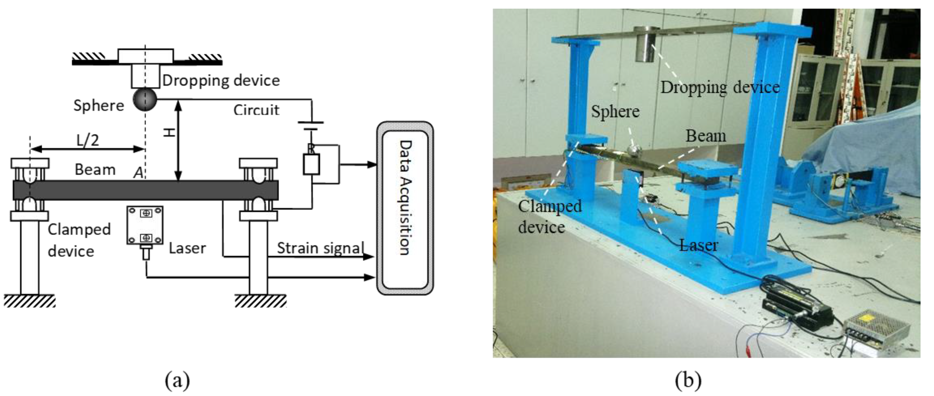
The experimental impact setup used in this study for the repeated impacts between the sphere and the beam is shown in Figure 3. The testing details can refer to the previous study [29,30]. The impact duration during impact is measured by the circuit system. The circuit system will be on (i.e., nonzero voltage) when the sphere contacts with the beam and the circuit system will be off (i.e., zero voltage) when the sphere separates from the beam. The laser sensor records the displacement of the beam during impact. 21 strain gauges are distributed at the bottom of the beam to measure the strain of the beam. The impact location and the distribution of the strain gauges are shown in Figure 4. The interval between each strain gauge is 26 mm. In the following section, the experimental results of strain gauges S14, S16, S18 and S20 are used to compare with the simulation results.
The material property and geometry used in this paper are listed in Table 2. The beam can be considered as a simply supported beam [30]. A total of 91 repeated impacts have been performed at the location A, i.e., the center of the beam, with different initial impact velocities. The repeated impact numbers are listed in Table 3. For example, the test starts with four repeated impacts (1st–4th) at the release height of 50 mm, followed by three repeated impacts (5th–7th) at the release height of 60 mm.
5. Results and Discussion
As mentioned above, the entire elastic transient responses of the beam can be directly solved by using the eigenfunction expansion method. In this section, the repeated transverse impacts problem descripted in Section 4 are simulated. The transient wave propagation during repeated impacts is firstly analyzed theoretically by using the eigenfunction expansion method and different local contact models. Then the eigenfucntion expansion method and spring-mass method [4] are compared to investigate the simulation on transient impact behaviors, which includes the contact force, the impact duration, the accumulated permanent indentation, the energy transformation, the coefficient of restitution and the separation velocity of the sphere. The simulations are compared with the experimental data.
5.1. Parameter Determinations
For the eigenfunction method, the convergence study on the number of truncated modes is conducted for the 91st repeated impact. Table 4 lists the main impact behaviors of the 91st repeated impact by combining the eigenfunction method and KK model [43]. It shows that good convergence can be achieved when truncation number reaches 20. In the following studies, the mode number is chosen as 20 for the analysis. In this paper, the first sub-impact is focused if the sub-impacts occur [30,46].
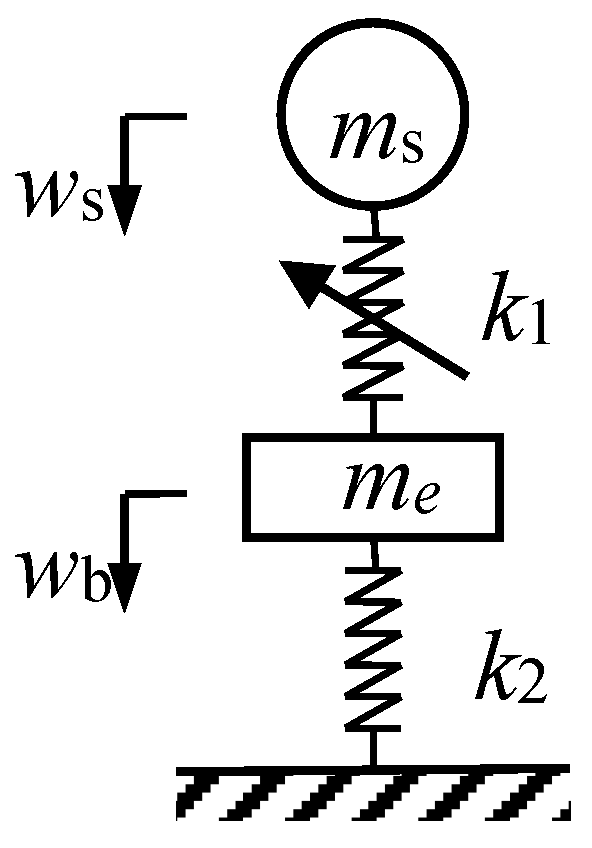
For the spring-mass method shown in Figure 5, is the nonlinear local contact stiffness, is the static stiffness of the beam at the impact location and is the equivalent mass of the beam at the impact location. It is a simplified model to simulate the repeated impact responses, in which the bending waves travel from the impact location to the ends of the beam and back many times during the impact, i.e., the beam behaves in a quasi-static manner and the wave propagation effect is neglected [4].
Assuming that the static load P is applied at the center of the beam, the deflection at the center of the simply supported beam is:
Hence, the static stiffness of the center of the beam can be calculated as:
The equivalent mass is also related to the impact location, and is defined by the circular frequency of the spring-mass model . Assuming that is equal to the fundamental nature circular frequency of the simply supported beam , the equivalent mass can be obtained as
The equations of motion of the spring-mass can be expressed as:
where the indentation. Equation (28) can be solved by using Runge-Kutta integration method.
To ensure the applicability of eigenfunction method and spring-mass method, the time interval should be small enough. For the following studies, s.
5.2. Transient Wave Propagation
Figure 6 shows the simulation results of transient stress distribution along the beam for the first impact of H = 50 mm at different times by using the eigenfunction method and Stronge model. Figure 6a plots the transient stress distribution during loading phase. It demonstrates that the wave dispersion of the high-frequency waves moves faster than that in low-frequency waves. Figure 6b plots the transient stress distribution during unloading phase and post-impact phase. It shows that as time going on, the high order waves would reflect from the ends of the beam, and complicate the stress patterns. Figure 6 has shown that the eigenfunction expansion method can simulate the phenomenon of the bending wave propagations very clearly. To further study the validity of the eigenfunction expansion method on simulating transient wave propagations of repeated transverse impacts, the following study will compare the simulated transient stress response of eigenfunction expansion method with experimental results.
5.2.1. The First Impact
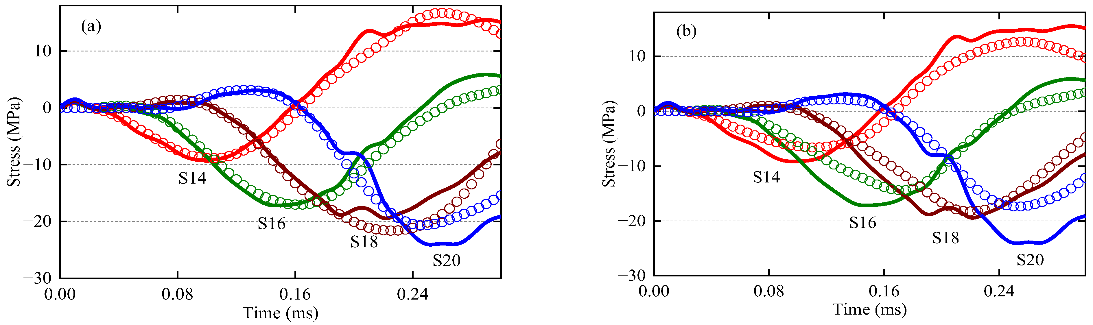
Figure 7 shows the transient stress responses of the eigenfunction expansion method results and experimental results at the strain gauges S14, S16, S18, S20 for the first impact of the total 91 impacts, i.e., the first impact at the release height 50 mm. The results of eigenfunction expansion method with Hertz and MJG contact models are shown in Figure 7a,b, respectively. The experimental results shown in Figure 7 illustrate that the impact indeed excites transient wave propagation. The transient wave propagation during the impact can be observed via the stress response. As shown in Figure 7a,b, the stresses in the beam are much smaller than the yield stress of the beam (345 MPa), therefore the global behavior of the beam caould be regarded as completely elastic and no global plastic deformation happens on the beam. As can be seen from Figure 7a,b, different local contact models can simulate different local impact behaviours and the eigenfunction expansion method can accurately predict the impact-induced transient wave propagations with appropriate contact models.
5.2.2. The 51st Repeated Impact
Figure 8 shows the transient stress responses of experimental results and eigenfunction expansion method results at the strain gauges S14, S16, S18, S20 for the 51st of the total 91 impacts, i.e., the first impact of the release height 210 mm. The results of eigenfunction expansion method with ML and CYM contact models are shown in Figure 8a,b, respectively. The experimental results shown in Figure 8 illustrate that the impact indeed excites transient wave propagation. The transient wave propagation during the impact can be observed clearly through the stress response. As shown in Figure 8a,b, the results of the 51st impact show that the stresses in the beam are much smaller than the yield stress of the beam (345 MPa). Therefore, the global behavior of the beam can be regarded as completely elastic and no global plastic deformation happens on the beam. As shown in Figure 8a, eigenfunction expansion method can accurately predict the impact-induced transient wave propagations with appropriate contact models. The large differences of the results of eigenfunction expansion method shown in Figure 8a,b demonstrate that the importance of selecting an appropriate contact model.
5.2.3. The 91st Repeated Impact
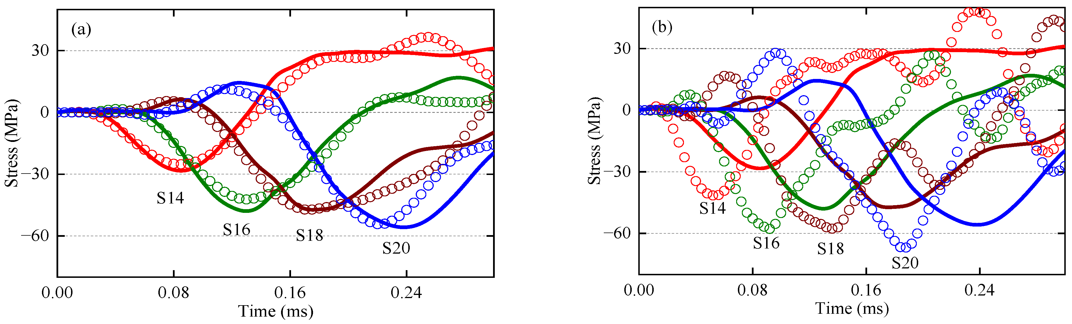
Figure 9 shows the transient stress responses of experimental results and eigenfunction expansion method results at the strain gauges S14, S16, S18, S20 corresponding to the last impact, i.e., the 91st impact of the release height 360 mm. The results of eigenfunction expansion method with KE and KK contact models are shown in Figure 9a,b, respectively. The experimental results shown in Figure 9 also demonstrate that impacts excite transient wave propagations. The transient wave propagation during the impact can be observed clearly through the stress response. As shown in Figure 9a,b, the results of the 91st impact show that the stresses in the beam are much smaller than the yield stress of the beam (345 MPa). Therefore, the global behavior of the beam can be regarded as completely elastic and no global plastic deformation happens on the beam. As shown in Figure 9a,b, different local contact models can simulate different local impact behaviors and the eigenfunction expansion method can accurately predict the impact-induced transient wave propagations with appropriate contact models.
5.3. Transient Impact Behaviors
5.3.1. Contact Force and Energy Transformation
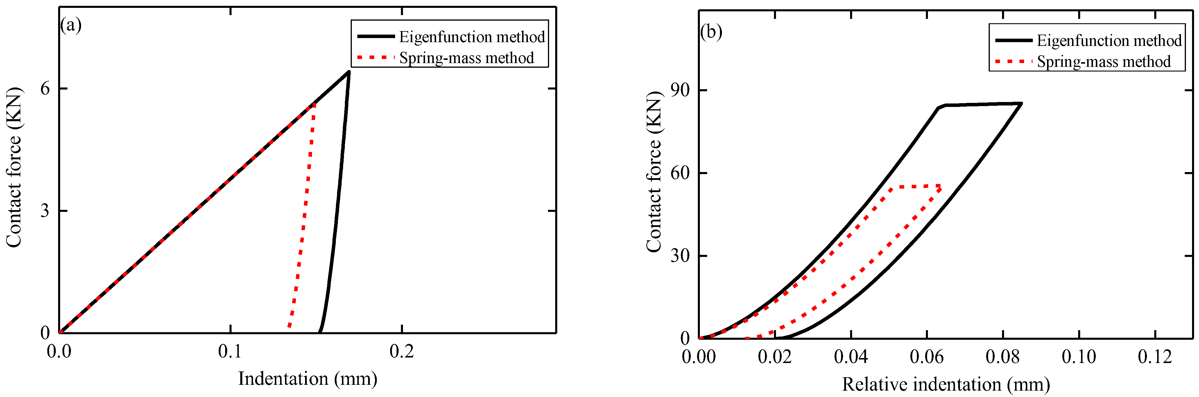
As shown in Table 3, 91 repeated impacts at the center of the beam have been conducted. By combining the eigenfunction expansion method and spring-mass method with Thornton local contact model, the theoretical contact force and contact force-indentation relations of the 1st (i.e., 50 mm release height) and the 91st (360 mm release height) impacts are shown in Figure 10 and Figure 11, respectively. The impact impulse P, contact work W, kinetic energy loss of the sphere ΔE, energy absorption of the beam Ua for the 1st and the 91st impacts are listed in Table 5.
Comparing the results shown in Figure 10 and Figure 11 and Table 5, the differences between the eigenfunction expansion method and spring-mass method are significant. Spring-mass method predicts the larger contact force, indentation, permanent indentation, impulse and contact work, but the smaller impact duration and energy absorption of the beam. For spring-mass method, due to the neglecting of wave propagation energy, less energy is transferred to structural vibrations and more energy is transferred to local contact zone, which results in higher contact force and shorter impact duration. For the results of first impact shown in Figure 10a, the predicted contact force and impact duration of spring-mass method are 13.30% higher and 4.12% shorter relative to eigenfunction method, respectively. For the results of 91st impact shown in Figure 10b, the predicted contact force and impact duration of spring-mass method model are 53.30% higher and 8.99% shorter relative to eigenfunction method, respectively. Therefore, higher modes of beam vibration should be taken into account to achieve a better estimation of the contact force and impact duration.
5.3.2. Impact Duration
As shown in Figure 12a,b, the impact duration of the last impact for every impact velocity are analyzed. The impact duration predicted by eigenfucntion expansion method and spring-mass method are compared with the experimental results. The plots show that the predicted impact duration by eigenfucntion expansion method is about 3.31% and 5.33% longer than those predicted by spring-mass method with Hertz contact model and ML contact model, respectively. It means that the eigenfunction expansion method and spring-mass method predict closely results of impact duration, and the wave propagation has slight influence on the impact duration of repeated impacts on one hand, on the other hand, it means that by using different local contact models, the eigenfunction expansion method can simulate different impact behaviors.
5.3.3. Accumulated Permanent Indentation
As shown in Figure 13a,b, the accumulated permanent indentation of the last impact for every impact velocity are analyzed. The accumulated permanent indentations predicted by eigenfucntion expansion method and spring-mass method are compared with the experimental results. The plots show that the accumulated permanent indentation predicted by eigenfucntion expansion method agree well with experimental results than spring-mass method. It means that the wave propagation has obvious influence on the accumulated permanent indentation of repeated impacts. Figure 13a,b shows that the accumulated permanent indentation predicted by eigenfucntion expansion method is maximally 44.46% and 69.97% less than those predicted by spring-mass method for UC model and MYC model, respectively. It means that by using different local contact models, large discrepancies can be obtained on simulating impact behaviors of eigenfunction expansion method. This demonstrates the importance of selecting appropriate local contact models.
5.3.4. Coefficient of Restitution
The coefficient of restitution (COR) is defined as the negative ratio of final relative velocity to initial relative velocity between the sphere and the beam at the impact location [30]. The calculations of the experimental COR require the velocity of the beam and the sphere at the end time of impact. In the experiments, the beam velocity is calculated from the measured displacement of the beam. The measured displacement is smoothed by using the Savitzky-Golay filtering algorithm, and the beam velocity is obtained by taking the derivative with respect to the smoothed beam displacement. The experimental separation velocity of the sphere is measured by solving the equations of the motion during separation stage, where the gravity is considered:
where and represent the end time of the first sub-impact and the beginning time of the subsequent sub-impact, respectively. and are the measured displacements of the beam at the contact location for time and , respectively.
As shown in Figure 14a,b, the coefficient of restitution of the last impact for every impact velocity are analyzed. The coefficient of restitution predicted by eigenfucntion expansion method and spring-mass method are compared with the experimental results. Comparing Figure 14a,b, it shows that the coefficient of restitution predicted by eigenfunction expansion method is maximally 63.15% and 63.67% smaller than that predicted by spring-mass for Stronge model and Thornton model, respectively. It means that the coefficient of restitution predicted by eigenfunction expansion method is agree well with experimental results than spring-mass method. It means that the wave propagation has obvious influence on the coefficient of restitution of repeated impacts, and eigenfunction expansion method is suitable for the transient responses of repeated transverse impacts on beams.
5.3.5. Separation Velocity
As shown in Figure 15a,b, the separation velocity of the sphere of the last impact for every impact velocity are analyzed. The separation velocity of the sphere predicted by eigenfunction expansion method and spring-mass method are compared with the experimental results. As shown, large differences could be found between the eigenfunction expansion method and spring-mass method. It means that the wave propagation effect has obvious influence on the separation velocity of the sphere under repeated impacts. The separation velocity of the sphere is known directly related to the kinetic energy loss of the sphere during the impacts. For spring-mass method, the smaller kinetic energy loss results in the larger absolute separation velocity of the sphere, as shown in Figure 15a,b. The comparison results show that eigenfunction expansion method is suitable for the transient responses of repeated transverse impacts on beams.
Moreover, the positive separation velocity of the sphere has been observed in the experimental results and the simulated results of eigenfunction expansion method. However, spring-mass method predicts negative separation velocity of the sphere. The separation velocity of the sphere either positive or negative determines the subsequent motion of the sphere, which determines the occurrence of sub-impact phenomenon [4]. The positive separation velocity of the sphere indicates that the sphere keeps moving in the dropping direction and will impact the beam again after finally separation upward and sub-impact can take place. The negative separation velocity of the sphere predicted by using the spring-mass means that the sphere reverses the direction of movement after impact and sub-impact phenomenon can rarely be observed.
6. Conclusions
The transient behavior of a flexible beam, driven by repeated transverse impact of a spherical projectile, are investigated in this study. The eigenfunction expansion method is firstly presented to solve the transient structure responses of beams. Then the new method can be used to solve the repeated impact responses of beams by combining the local contact models. In order to verify the validity, the results of the new method as well as the spring-mass model are compared with the experimental data, where a simply-supported beam is repeatedly struck by a sphere. The main findings are concluded as follows.
- (1)
- The eigenfunction expansion method could predict the wave propagation during repeated impacts on beams, and the results agree well with the experiments.
- (2)
- For transient impact behaviors related to energy dissipations, including the accumulated permanent indentation, the coefficient of restitution and the separation velocity of the sphere, the results of eigenfunction expansion method agree well with the experimental results, while the results of spring-mass method have large discrepancy with the experimental results.
- (3)
- For impact duration, the simulation results of eigenfunction expansion method and spring-mass method both agree well with the experimental results.
- (4)
- The differences for the eigenfunction expansion method and spring-mass method are that, for eigenfunction expansion method the energy can be dissipated by wave propagations, structural vibrations as well as local contact behaviors, while the spring-mass method only dissipates energy thorough structural vibrations and local contact behaviors.
- (5)
- The eigenfunction expansion method appears to be suitable for the transient responses of repeated transverse impacts on beams, especially for the study of impact-induced wave propagations.
Author Contributions
Conceptualization, H.W. and H.Z.; Data curation, H.W., S.M. and X.W.; Funding acquisition, H.W.; Investigation, H.W., S.M. and X.W.; Methodology, H.W.; Project administration, H.W.; Supervision, H.W. and H.Z.; Validation, H.W.; Visualization, H.W.; Writing—original draft, H.W.; Writing—review & editing, H.W. All authors have read and agreed to the published version of the manuscript.
Funding
This research was funded by the National Natural Science Foundation of China (Grant No. 11902143), the Postdoctoral Research Funding Program of Jiangsu province (2020Z056) and the Postgraduate Research & Practice Innovation Program of Jiangsu Province (KYCX22_1281).
Institutional Review Board Statement
Not applicable.
Informed Consent Statement
Not applicable.
Data Availability Statement
The data presented in this study are available on request from the corresponding author.
Conflicts of Interest
The authors declare no conflict of interest.
References
- Peterson, V.; Ansell, A.; Hallgren, M. On the residual static and impact capacity of shear-reinforced concrete beams subjected to an initial impact. Appl. Sci. 2022, 12, 11377. [Google Scholar] [CrossRef]
- Christoforou, A.P.; Yigit, A.S. Effect of flexibility on low velocity impact Response. J. Sound Vib. 1998, 217, 563–578. [Google Scholar] [CrossRef]
- Yigit, A.S.; Christoforou, A.P.; Majeed, M.A. A nonlinear visco-elastoplastic impact model and the coefficient of restitution. Nonlinear Dynam. 2011, 66, 509–521. [Google Scholar] [CrossRef]
- Pashah, S.; Massenzio, M.; Jacquelin, E. Prediction of structural response for low velocity impact. Int. J. Impact Eng. 2008, 35, 119–132. [Google Scholar] [CrossRef]
- Schiehlen, W.; Seifried, R.; Eberhard, P. Elastoplastic phenomena in multibody impact dynamics. Comput. Method Appl. M. 2006, 195, 6874–6890. [Google Scholar] [CrossRef]
- Olsson, R. Mass criterion for wave controlled impact response of composite Plates. Compos. Part A-Appl. S. 2000, 31, 879–887. [Google Scholar] [CrossRef]
- Yigit, A.S.; Christoforou, A.P. Limits of asymptotic solutions in low-velocity impact of composite plates. Compos. Struct. 2007, 81, 568–574. [Google Scholar] [CrossRef]
- Olsson, R. Impact response of orthotropic composite plates predicted from a one-parameter differential equation. AIAA J. 1992, 30, 1587–1596. [Google Scholar] [CrossRef]
- Christoforou, A.P.; Yigit, A.S.; Majeed, M. Low-velocity impact response of structures with local plastic deformation: Characterization and scaling. J. Comput. Nonlin. Dyn. 2013, 8, 011012. [Google Scholar] [CrossRef]
- Doyle, J.F. Wave Propagation in Structures: An FFT-Based Spectral Analysis Methodology, 1st ed.; Springer: New York, NY, USA, 1989; pp. 80–90. [Google Scholar]
- Schwieger, H. Central deflection of a transversely struck beam. Exp. Mech. 1970, 10, 166–169. [Google Scholar] [CrossRef]
- Malekzadeh, K.S.; Khalili, M.R.; Gorgabad, A.V. Dynamic response of composite sandwich beams with arbitrary functionally graded cores subjected to low-velocity impact. Mech. Adv. Mater. Struc. 2015, 22, 605–618. [Google Scholar] [CrossRef]
- Kabir, M.Z.; Shafei, E. Analytical and numerical study of FRP retrofitted RC beams under low velocity impact. Sci. Iran. 2009, 16, 415–428. [Google Scholar]
- Jacquelin, E.; Laine, J.P.; Bennani, A.; Massenzio, M. A modelling of an impacted structure based on constraint modes. J. Sound Vib. 2007, 301, 789–802. [Google Scholar] [CrossRef]
- Pashah, S.; Massenzio, M.; Jacquelin, E. Structural response of impacted structure described through anti-oscillators. Int. J. Impact Eng. 2008, 35, 471–486. [Google Scholar] [CrossRef]
- Christoforou, A.P.; Yigit, A.S. Characterization of impact in composite plates. Compos. Struct. 1998, 43, 15–24. [Google Scholar] [CrossRef]
- Eringen, A.C. Transverse impact on beams and plates. Int. J. Appl. Mech. 1953, 20, 461–468. [Google Scholar] [CrossRef]
- Yin, X.C.; Qin, Y.; Zou, H. Transient responses of repeated impact of a beam against a stop. Int. J. Solids Struct. 2007, 44, 7323–7339. [Google Scholar] [CrossRef] [Green Version]
- Yin, X.C.; Yue, Z.Q. Transient plane-strain response of multilayered elastic cylinders to axisymmetric impulse. Int. J. Appl. Mech. 2002, 69, 825–835. [Google Scholar] [CrossRef]
- Eringen, A.C.; Suhubi, E.S.; Chao, C.C. Elastodynamics, Vol. II. In Linear Theory, 1st ed.; Academic Press: New York, NY, USA, 1975. [Google Scholar]
- Natsuki, T.; Natsuki, J. Transverse impact of double-layered grapheme sheets on an elastic foundation. Int. J. Eng. Sci. 2018, 124, 41–48. [Google Scholar] [CrossRef]
- Johnson, K.L. Contact Mechanics, 1st ed.; Cambridge University Press: New York, NY, USA, 1987. [Google Scholar]
- Jackson, R.; Chusoipin, I.; Green, I. A finite element study of the residual stress and deformation in hemispherical contacts. J. Tribol. 2005, 127, 484–493. [Google Scholar] [CrossRef] [Green Version]
- Du, Y.; Wang, S. Energy dissipation in normal elastoplastic impact between two spheres. Int. J. Appl. Mech. 2009, 76, 061010. [Google Scholar] [CrossRef]
- Brake, M.R. An analytical elastic-perfectly plastic contact model. Int. J. Solids Struct. 2012, 49, 3129–3141. [Google Scholar] [CrossRef] [Green Version]
- Brake, M.R. An analytical elastic plastic contact model with strain hardening and frictional effects for normal and oblique impacts. Int. J. Solids Struct. 2015, 62, 104–123. [Google Scholar] [CrossRef]
- Ghaednia, H.; Marghitu, D.B.; Jackson, R.L. Predicting the permanent deformation after the impact of a rod with a flat surface. J. Tribol. 2015, 137, 011403. [Google Scholar] [CrossRef]
- Chong, W.W.F.; Cruz, M.D.L. Elastoplastic contact of rough surfaces: A line contact model for boundary regime of lubrication. Meccanica 2014, 49, 1177–1191. [Google Scholar] [CrossRef] [Green Version]
- Wang, H.; Yin, X.C.; Deng, Q.M.; Yu, B.; Hao, Q.M.; Dong, X.Y. Experimental and theoretical analyses of elastic-plastic repeated impacts by considering wave Effects. Eur. J. Mech. A-Solid. 2017, 65, 212–222. [Google Scholar] [CrossRef]
- Wang, H.; Yin, X.C.; Qi, X.L.; Deng, Q.M.; Yu, B.; Hao, Q.M. Experimental and theoretical analysis of the elastic-plastic normal repeated impacts of a sphere on a beam. Int. J. Solids Struct. 2017, 109, 131–142. [Google Scholar] [CrossRef]
- Sadighi, M.; Alderliesten, R. Impact fatigue, multiple and repeated low-velocity impacts on FRP composites: A review. Compos Struct. 2022, 297, 115962. [Google Scholar] [CrossRef]
- Cho, S.R.; Truong, D.D.; Shin, H.K. Repeated lateral impacts on steel beams at room and sub-zero temperatures. Int. J. Impact. Eng. 2014, 72, 75–84. [Google Scholar] [CrossRef]
- Truong, D.D.; Jung, H.J.; Shin, H.K.; Cho, S.R. Response of low-temperature steel beams subjected to single and repeated lateral impacts. Int. J. Nav. Arch. Ocean Eng. 2018, 10, 670–682. [Google Scholar] [CrossRef]
- Li, L.; Sun, L. Experimental and numerical investigations of crack behavior and life prediction of 18Cr2Ni4WA steel subjected to repeated impact loading. Eng. Fail. Anal. 2016, 65, 11–25. [Google Scholar] [CrossRef]
- He, X.; Soares, C.G. Experimental study on the dynamic behavior of beams under repeated impacts. Int. J. Impact. Eng. 2021, 147, 103724. [Google Scholar] [CrossRef]
- Guo, Y.Y.; Yin, X.C.; Yu, B.; Hao, Q.M.; Xiao, X.; Jiang, L.; Wang, H.; Chen, C.Q.; Xie, W.H.; Ding, H.P.; et al. Experimental analysis of dynamic behavior of elastic visco-plastic beam under repeated mass impacts. Int. J. Impact. Eng. 2023, 171, 104371. [Google Scholar] [CrossRef]
- Hao, Q.M.; Yin, X.C.; Qian, P.B.; Wang, H.; Ding, H.P.; Yu, B.; Deng, Q.M.; Dong, X.Y.; Qi, X.L. Transient Impact Analysis of Elastic-plastic Beam with Strain-Rate Sensitivity. Int. J. Impact. Eng. 2021, 153, 103865. [Google Scholar] [CrossRef]
- Thornton, C. Coefficient of restitution for collinear collisions of elastic-perfectly plastic spheres. Int. J. Appl. Mech. 1997, 64, 383–386. [Google Scholar] [CrossRef]
- Abrate, S. Impact on Composite Structures, 1st ed.; Cambridge University Press: New York, NY, USA, 1998. [Google Scholar]
- Stronge, W.J. Impact Mechanics, 1st ed.; Cambridge University Press: London, UK, 2000. [Google Scholar]
- Kogut, L.; Etsion, I. Elastic-plastic contact analysis of a sphere and a rigid flat. Int. J. Appl. Mech. 2002, 69, 657–662. [Google Scholar] [CrossRef] [Green Version]
- Etsion, I.; Kligerman, Y.; Kadin, Y. Unloading of an elastic-plastic loaded spherical contact. Int. J. Solids Struct. 2005, 42, 3716–3729. [Google Scholar] [CrossRef]
- Kogut, L.; Komvopoulos, K. Analysis of the spherical indentation cycle for elastic perfectly plastic solids. J. Mater Res. 2004, 19, 3641–3653. [Google Scholar] [CrossRef]
- Majeed, M.A.; Yigit, A.S.; Christoforou, A.P. Elastoplastic contact/impact of rigidly supported composites. Compos. Part B-Eng. 2012, 43, 1244–1251. [Google Scholar] [CrossRef]
- Ma, D.; Liu, C. Contact law and coefficient of restitution in elastoplastic spheres. Int. J. Appl. Mech. 2015, 82, 121006. [Google Scholar] [CrossRef]
- Timoshenko, S. Vibration Problems in Engineering, 1st ed.; D. Van Nostrand Company: New York, NY, USA, 1974. [Google Scholar]
Figure 1.
Illustration of a beam configuration.

Figure 2.
Sphere-beam impact system.

Figure 3.
The experimental setup: (a) schematic diagram; (b) practical setup.

Figure 4.
Illustrations for the experiments: (a) impact location A (top view); (b) distribution of strain gauges (upward view).
Figure 4.
Illustrations for the experiments: (a) impact location A (top view); (b) distribution of strain gauges (upward view).

Figure 5.
Two degree-of-freedom spring-mass model.

Figure 6.
Transient stress distribution along the beam of the first impact of H = 50 mm, with Stronge contact model: (a) loading phase; (b) unloading phase and post-impact phase.
Figure 6.
Transient stress distribution along the beam of the first impact of H = 50 mm, with Stronge contact model: (a) loading phase; (b) unloading phase and post-impact phase.

Figure 7.
Stress responses of the first impact of H = 50 mm: (a) Experimental results (Solid line) and eigenfunction method results (Scatter) with Hertz model; (b) Experimental results (Solid line) and eigenfunction method results (Scatter) with MJG model.
Figure 7.
Stress responses of the first impact of H = 50 mm: (a) Experimental results (Solid line) and eigenfunction method results (Scatter) with Hertz model; (b) Experimental results (Solid line) and eigenfunction method results (Scatter) with MJG model.

Figure 8.
Stress responses of the 51st impact (first impact of H = 210 mm): (a) Experimental results (Solid line) and eigenfunction method results (Scatter) with ML model; (b) Experimental results (Solid line) and eigenfunction method results (Scatter) with CYM model.
Figure 8.
Stress responses of the 51st impact (first impact of H = 210 mm): (a) Experimental results (Solid line) and eigenfunction method results (Scatter) with ML model; (b) Experimental results (Solid line) and eigenfunction method results (Scatter) with CYM model.

Figure 9.
Stress responses of the 91st impact (H = 360 mm): (a) Experimental results (Solid line) and eigenfunction method results (Scatter symbols) with KE model; (b) Experimental results (Solid line) and eigenfunction method results (Scatter symbols) with KK model.
Figure 9.
Stress responses of the 91st impact (H = 360 mm): (a) Experimental results (Solid line) and eigenfunction method results (Scatter symbols) with KE model; (b) Experimental results (Solid line) and eigenfunction method results (Scatter symbols) with KK model.

Figure 10.
Contact force responses by eigenfunction expansion method and spring-mass method (with Thornton contact model): (a) the 1st impact, V01 = 0.990 m/s; (b) the 91st impact, V091 = 2.656 m/s.
Figure 10.
Contact force responses by eigenfunction expansion method and spring-mass method (with Thornton contact model): (a) the 1st impact, V01 = 0.990 m/s; (b) the 91st impact, V091 = 2.656 m/s.

Figure 11.
Contact force-Indentation relations by eigenfunction expansion method and spring-mass method (with Thornton contact model): (a) the 1st impact, V01 = 0.990 m/s; (b) the 91st impact, V091 = 2.656 m/s.
Figure 11.
Contact force-Indentation relations by eigenfunction expansion method and spring-mass method (with Thornton contact model): (a) the 1st impact, V01 = 0.990 m/s; (b) the 91st impact, V091 = 2.656 m/s.

Figure 12.
Comparison of impact duration: (a) Hertz model; (b) ML model.

Figure 13.
Comparison of the accumulated permanent indentation: (a) UC model; (b) MYC model.

Figure 14.
Comparison of coefficient of restitution (COR): (a) Stronge model; (b) Thornton model.

Figure 15.
Comparison of separation velocity of the sphere: (a) KK model; (b) KE model.

Table 2.
Material properties and geometry.
| Sphere (Gr 15) | Simply Supported Beam (Q345) | ||
|---|---|---|---|
| 35.000 (mm) | 780.0 (mm) | ||
| 27.80 (mm) | |||
| 60.00 (mm) | |||
| 7800 (kg/m3) | 7800 (kg/m3) | ||
| 1.400 (kg) | 10.929 (kg) | ||
| 208,000 (MPa) | 210,000 (MPa) | ||
| 2555 (MPa) | 345 (MPa) | ||
| 0.3 | 0.3 | ||
Table 3.
Release height (H) and repeated impact numbers.
| H (mm) | Number of Impacts | H (mm) | Number of Impacts | H (mm) | Number of Impacts | H (mm) | Number of Impacts |
|---|---|---|---|---|---|---|---|
| 50 | 4 | 130 | 7 | 210 | 3 | 290 | 3 |
| 60 | 3 | 140 | 2 | 220 | 8 | 300 | 2 |
| 70 | 3 | 150 | 2 | 230 | 2 | 310 | 1 |
| 80 | 3 | 160 | 2 | 240 | 5 | 320 | 1 |
| 90 | 3 | 170 | 2 | 250 | 2 | 330 | 3 |
| 100 | 2 | 180 | 4 | 260 | 2 | 340 | 3 |
| 110 | 2 | 190 | 2 | 270 | 2 | 350 | 1 |
| 120 | 2 | 200 | 7 | 280 | 2 | 360 | 1 |
Table 4.
Convergence of the truncated mode number.
| Modes | COR | |||
|---|---|---|---|---|
| 10 | 0.11000 | 0.11902 | 0.23238 | 0.36159 |
| 20 | 0.11200 | 0.10761 | 0.22679 | 0.39040 |
| 50 | 0.11200 | 0.10746 | 0.22681 | 0.39034 |
| 100 | 0.11200 | 0.10745 | 0.22682 | 0.39036 |
| 200 | 0.11200 | 0.10745 | 0.22682 | 0.39036 |
Table 5.
Impulse (P), contact work (W), energy absorption of the beam (Ua) and kinetic energy loss of the sphere (ΔE) of eigenfunction method and spring-mass method for the first and 91st repeated impact.
Table 5.
Impulse (P), contact work (W), energy absorption of the beam (Ua) and kinetic energy loss of the sphere (ΔE) of eigenfunction method and spring-mass method for the first and 91st repeated impact.
| Theoretical Methods | P (N.s) | W (N.m) | ΔE (N.m) | Ua (N.m) | P (N.s) | W (N.m) | ΔE (N.m) | Ua (N.m) |
|---|---|---|---|---|---|---|---|---|
| V01 = 0.990 m/s | V091 = 2.656 m/s | |||||||
| Eigenfunction expansion method | 1.235 | 0.383 | 0.678 | 0.295 | 3.282 | 0.708 | 4.873 | 4.165 |
| Spring-mass method | 1.404 | 0.496 | 0.681 | 0.185 | 5.125 | 1.789 | 4.240 | 2.451 |
Disclaimer/Publisher’s Note: The statements, opinions and data contained in all publications are solely those of the individual author(s) and contributor(s) and not of MDPI and/or the editor(s). MDPI and/or the editor(s) disclaim responsibility for any injury to people or property resulting from any ideas, methods, instructions or products referred to in the content. |
© 2023 by the authors. Licensee MDPI, Basel, Switzerland. This article is an open access article distributed under the terms and conditions of the Creative Commons Attribution (CC BY) license (https://creativecommons.org/licenses/by/4.0/).
Share and Cite
MDPI and ACS Style
Wang, H.; Mao, S.; Wu, X.; Zhang, H. Transient Responses of Repeated Transverse Impacts on Beams. Appl. Sci. 2023, 13, 1115. https://0-doi-org.brum.beds.ac.uk/10.3390/app13021115
AMA Style
Wang H, Mao S, Wu X, Zhang H. Transient Responses of Repeated Transverse Impacts on Beams. Applied Sciences. 2023; 13(2):1115. https://0-doi-org.brum.beds.ac.uk/10.3390/app13021115
Chicago/Turabian StyleWang, Hui, Shunyuan Mao, Xiaomao Wu, and Huiling Zhang. 2023. "Transient Responses of Repeated Transverse Impacts on Beams" Applied Sciences 13, no. 2: 1115. https://0-doi-org.brum.beds.ac.uk/10.3390/app13021115
Note that from the first issue of 2016, this journal uses article numbers instead of page numbers. See further details here.