
Wideband, High-Gain, and Compact Four-Port MIMO Antenna for Future 5G Devices Operating over Ka-Band Spectrum

 , , and
Abstract
:1. Introduction
- The compact size and simplified geometry;
- Wide operational band and high gain;
- Low mutual coupling between MIMO elements;
- Good values of MIMO parameters, such as, ECC, CCL, DG, and MEG.
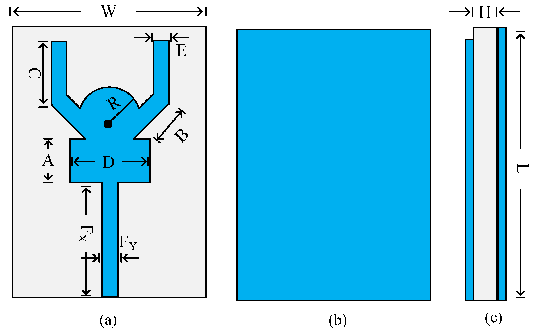
2. Wideband Antenna Designing
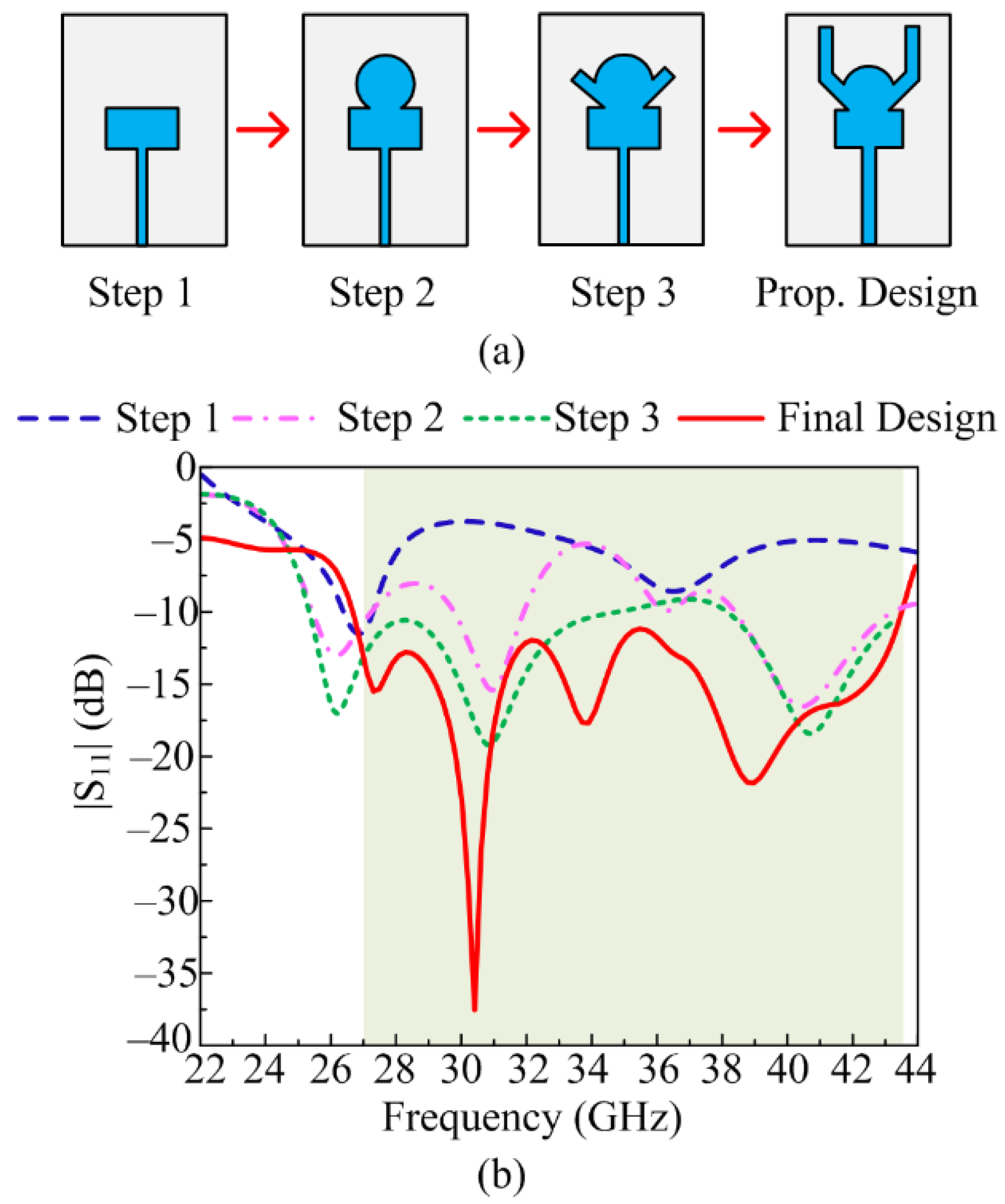
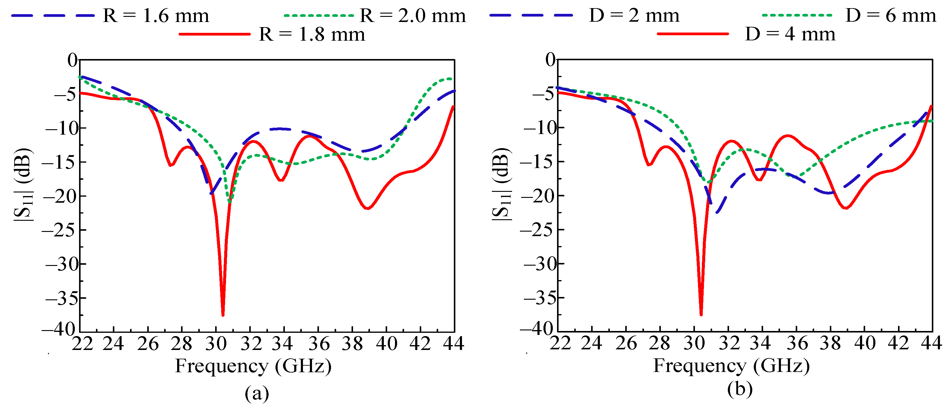
2.1. Design Methodology
2.2. Results of Unit Elements
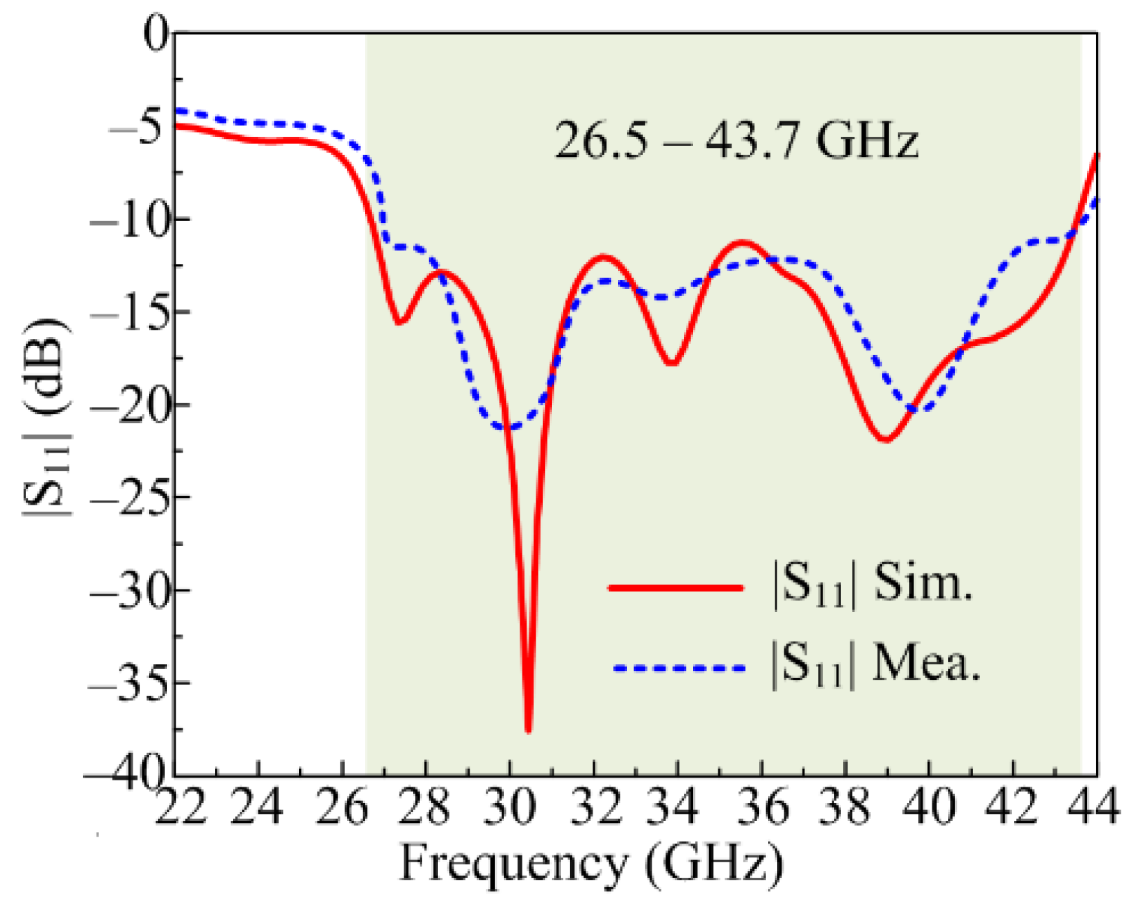
2.2.1. |S11|
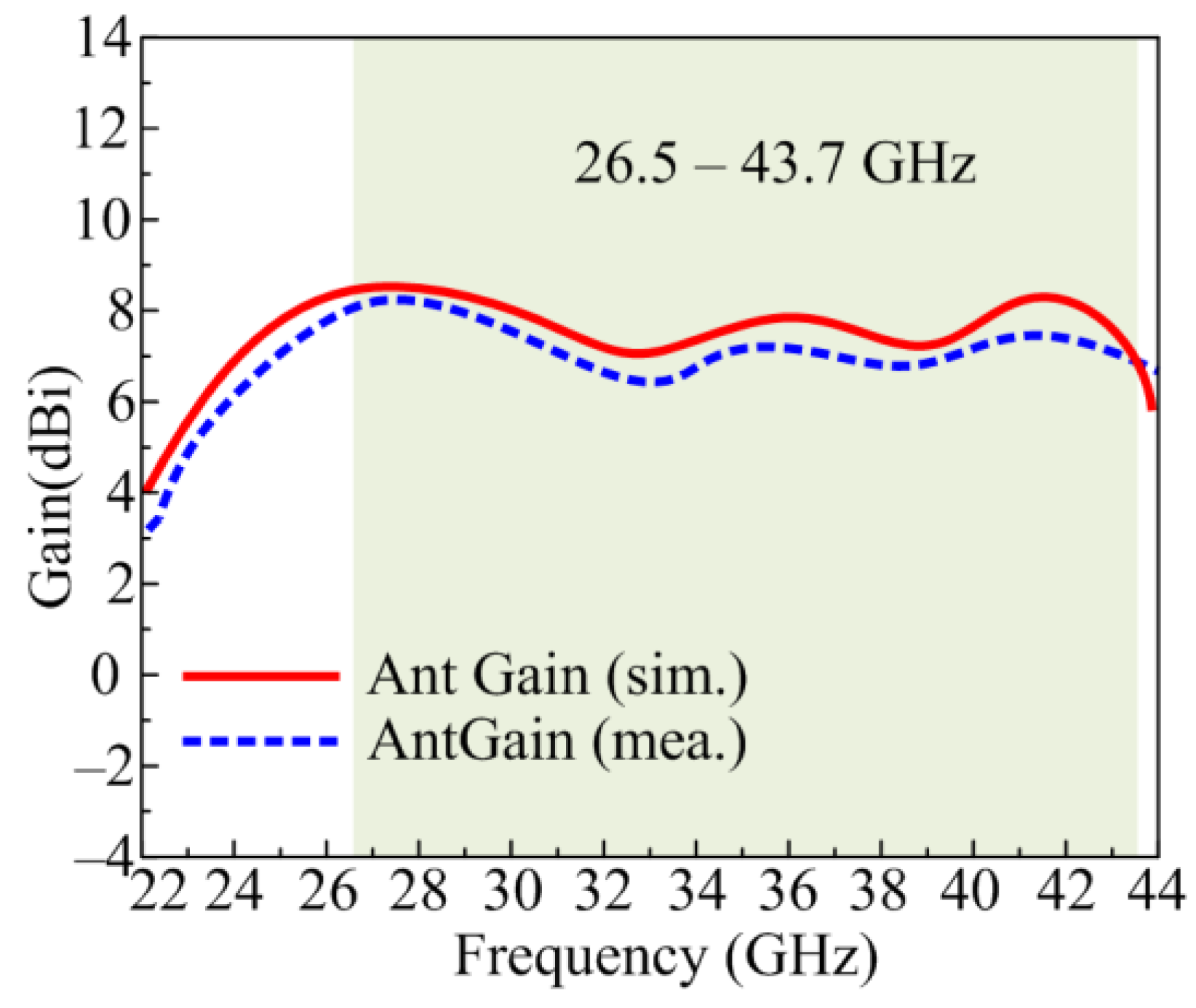
2.2.2. Gain
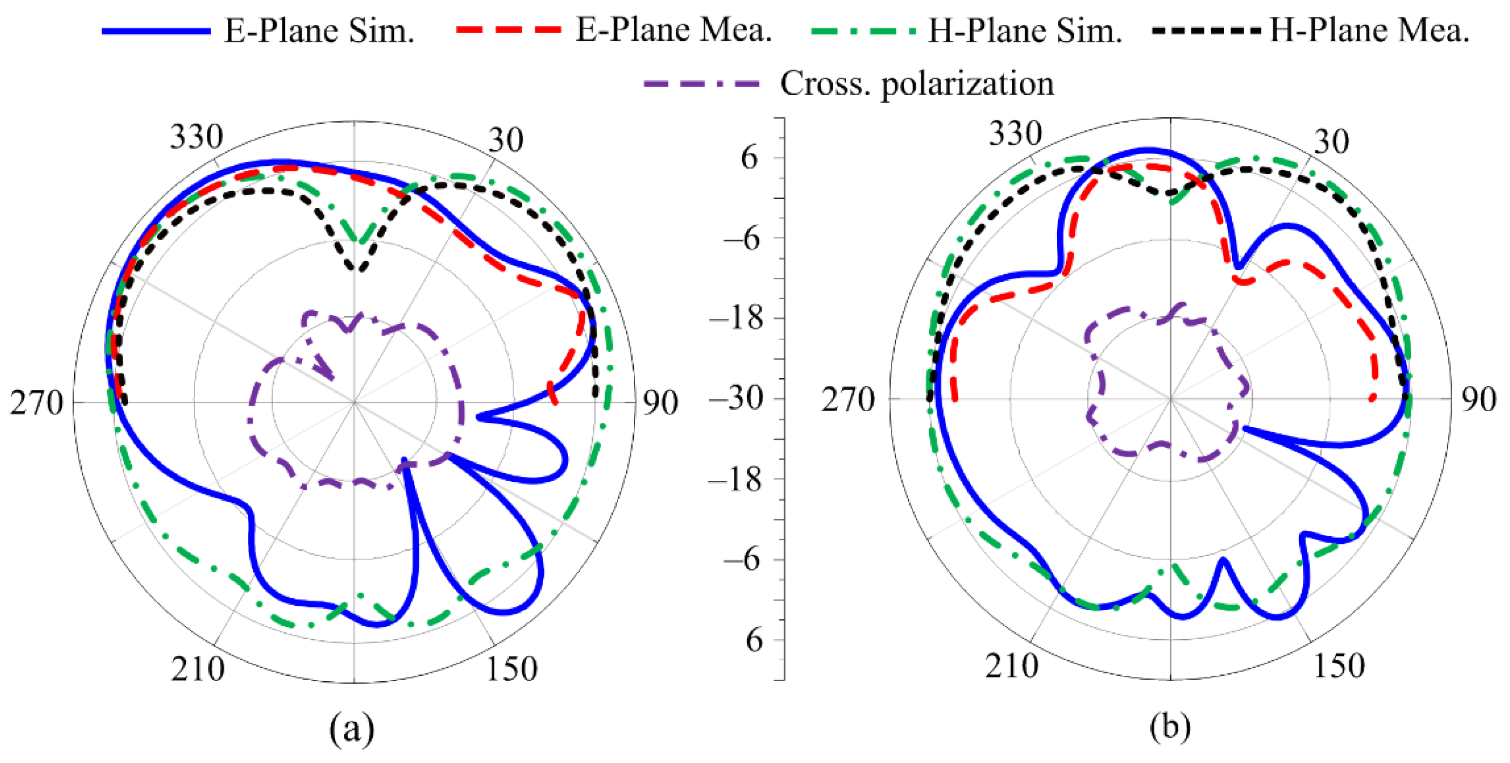
2.2.3. Radiation Pattern
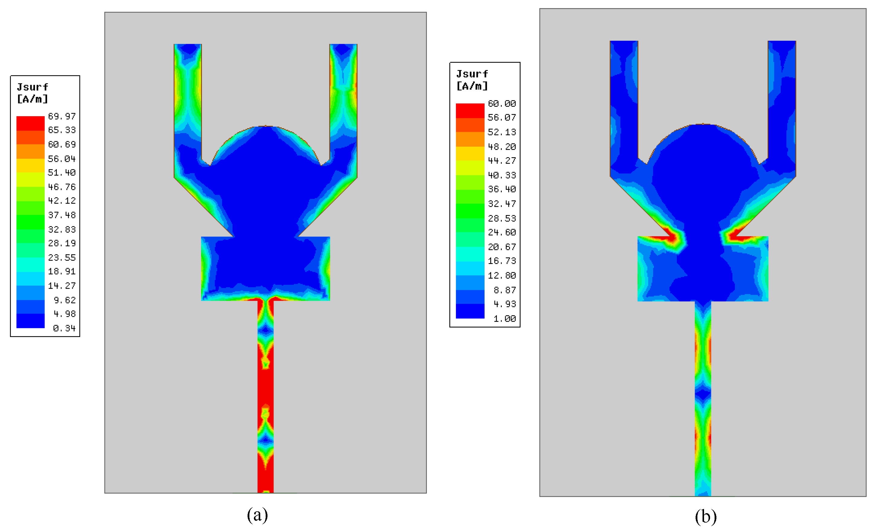
2.2.4. Surface Current Density
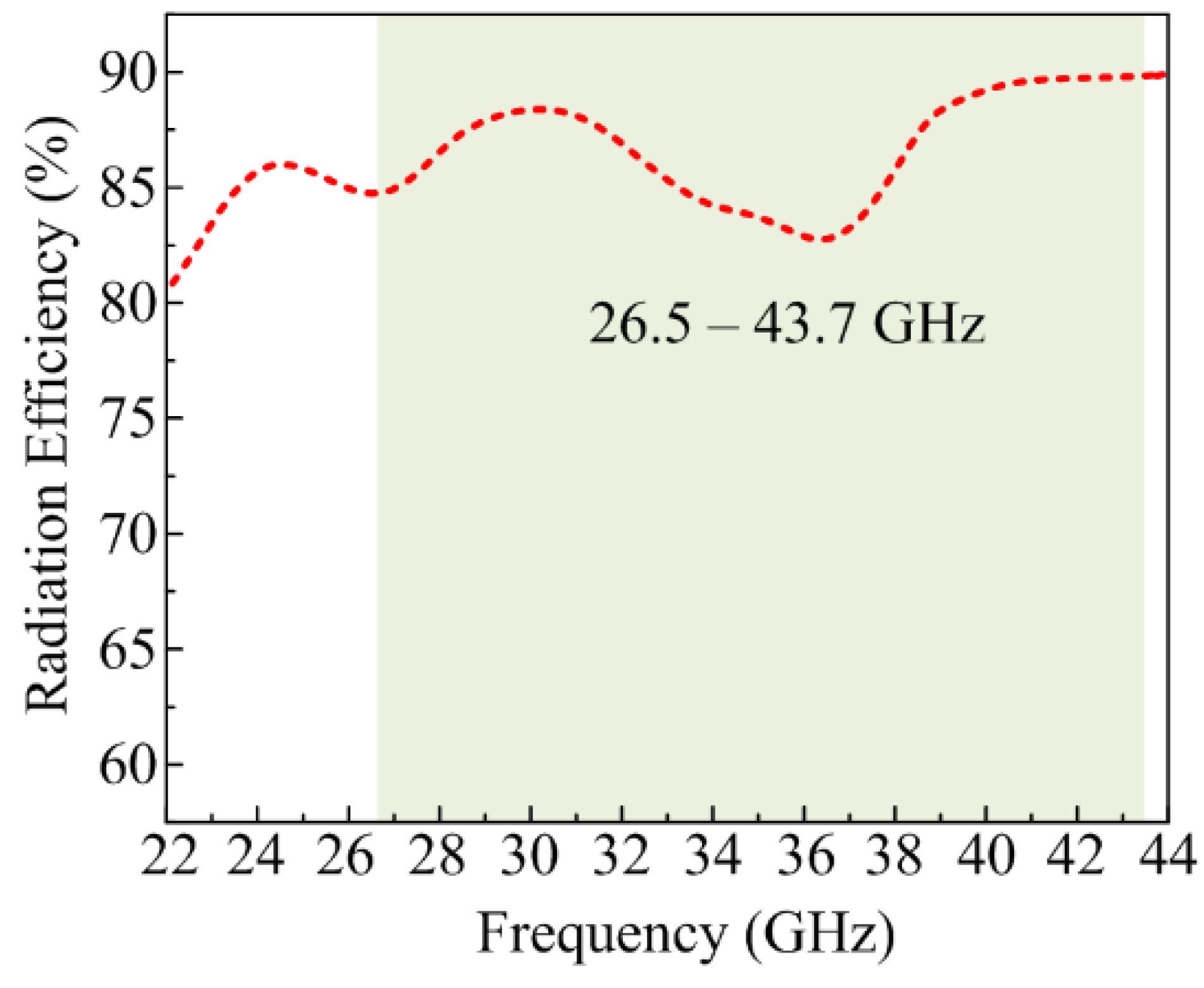
2.2.5. Radiation Efficiency
3. Four-Port MIMO Antenna
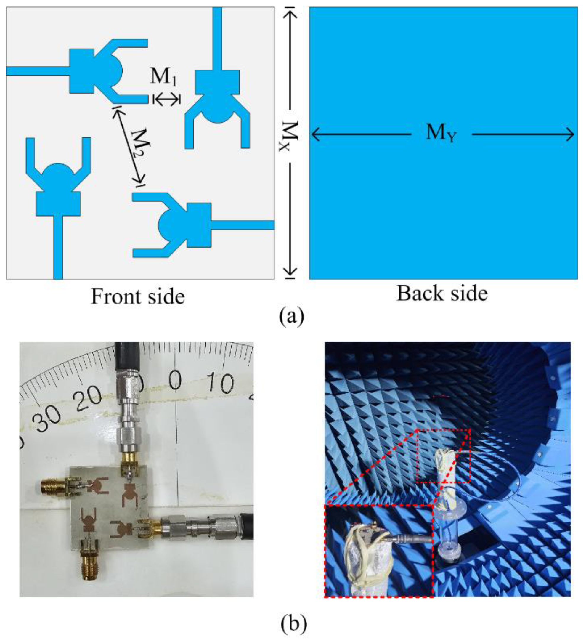
3.1. MIMO Antenna Design
3.2. Results and Discussion
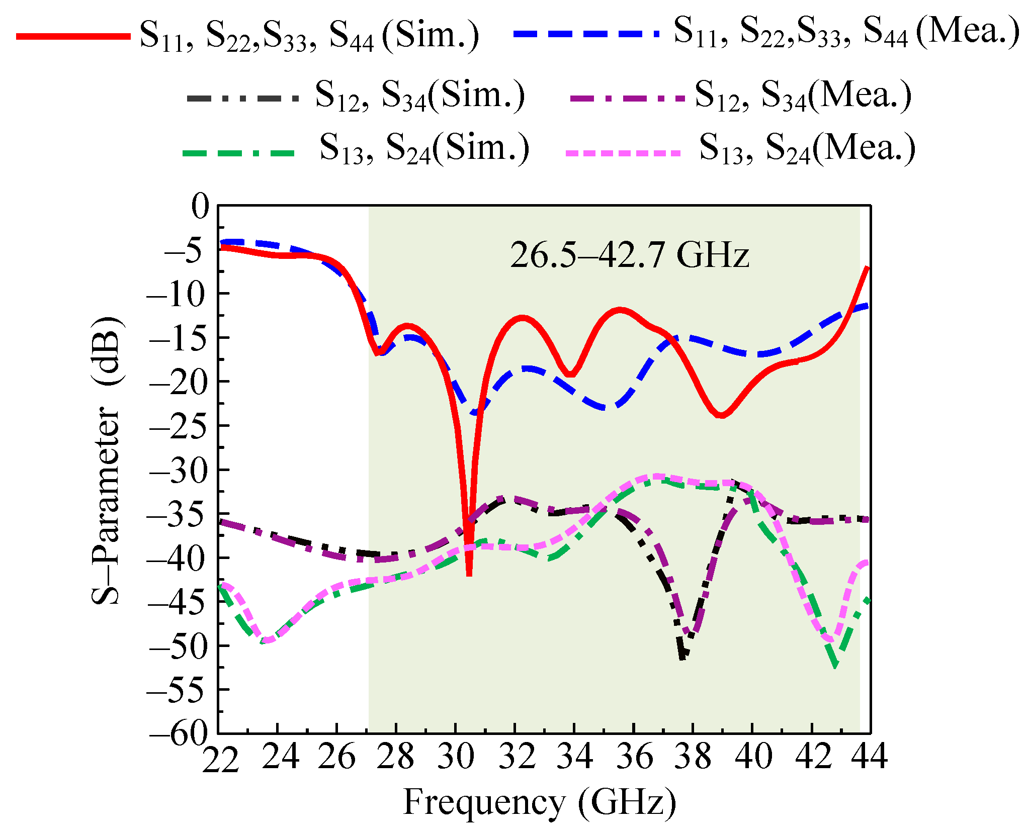
3.2.1. S-parameters
- The fabrication tolerance of apparatus used for fabrication of antenna;
- Measurement setup tolerance due to usage of old wires;
- Connectors used in measurements as mismatching occur due to connectors at higher frequency due to increase in losses on connectors.
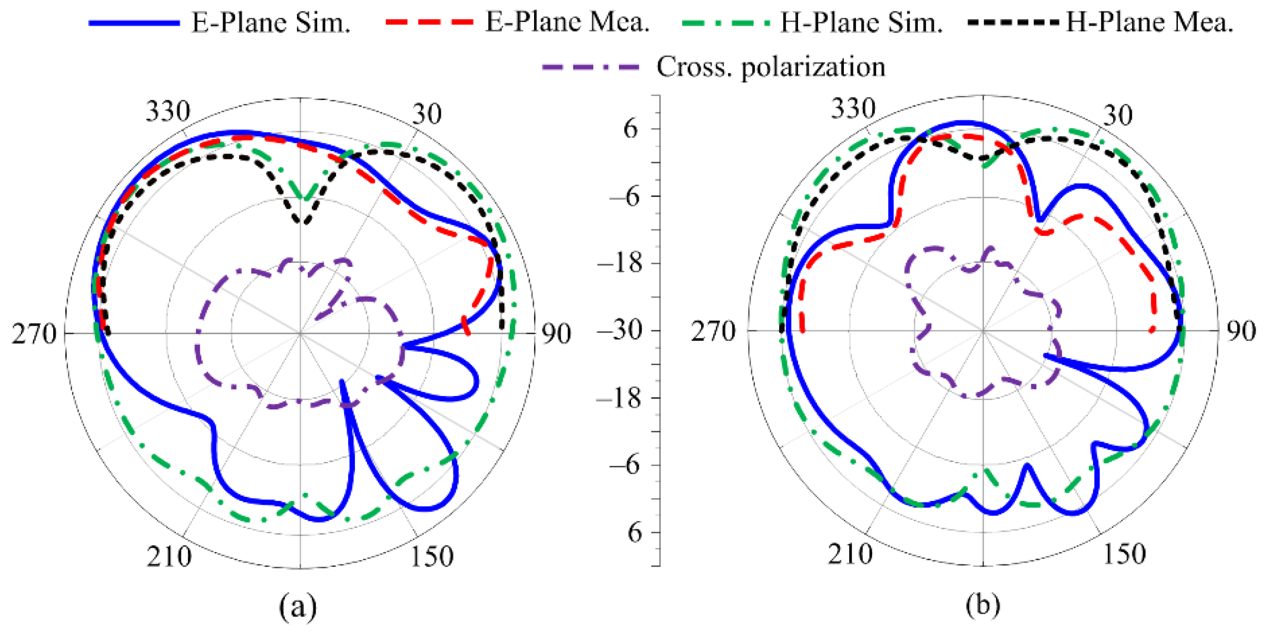
3.2.2. Radiation Pattern of MIMO Antenna
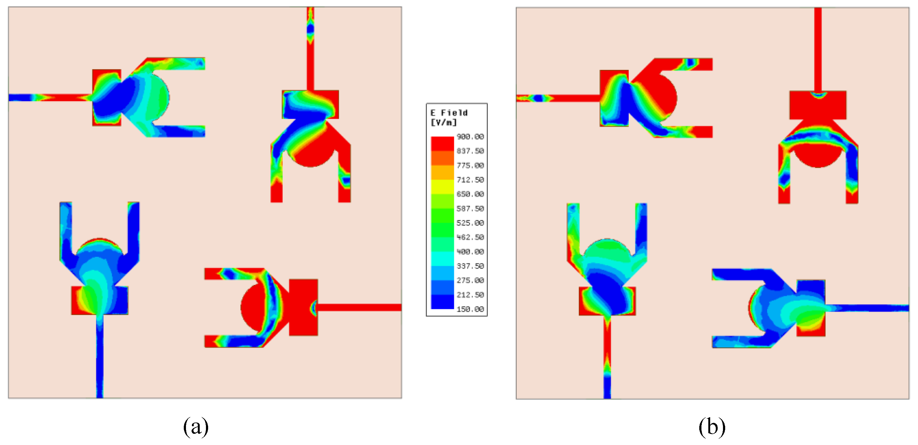
3.2.3. Electric Field Distribution
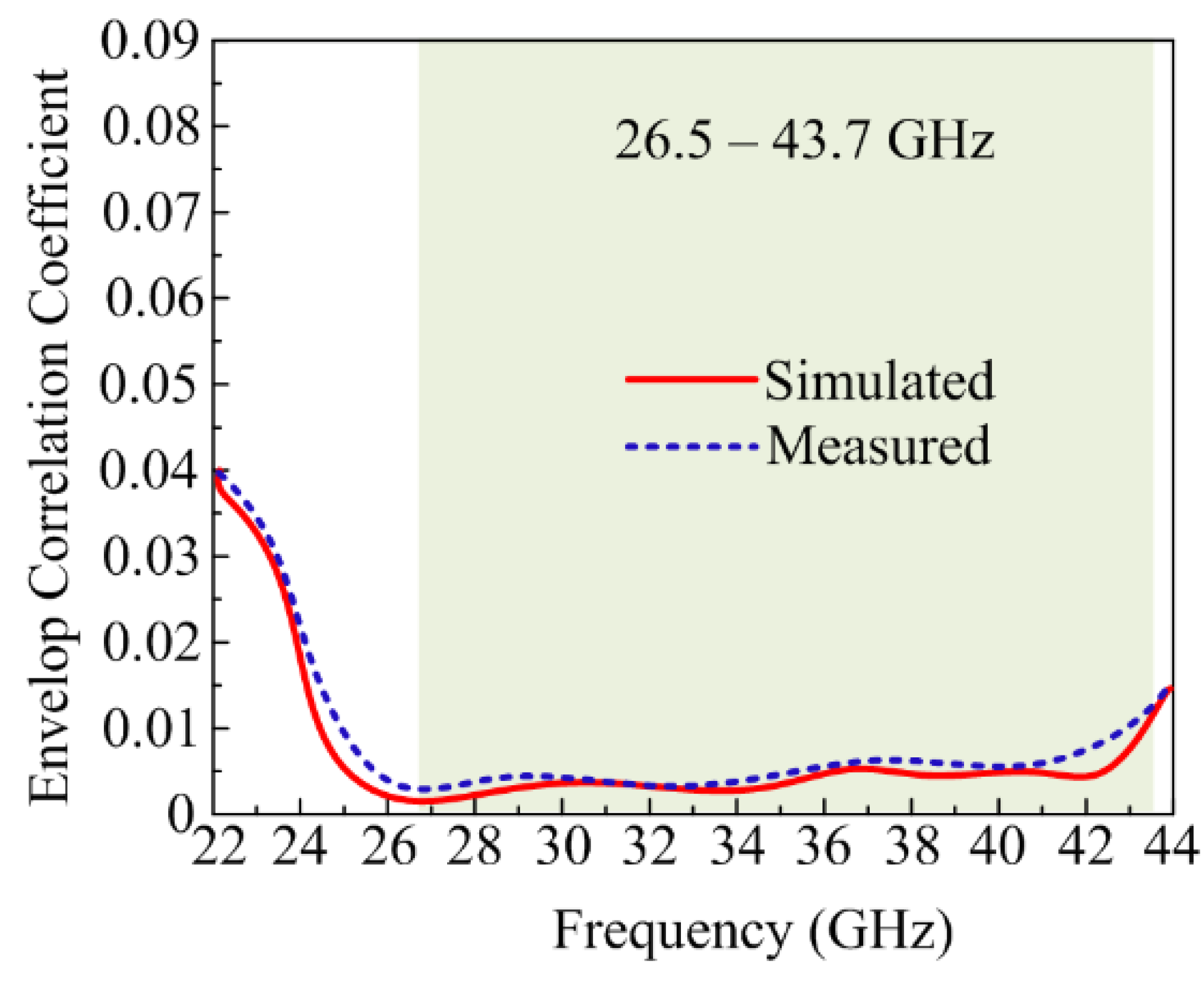
3.2.4. Envelop Correlation Coefficient
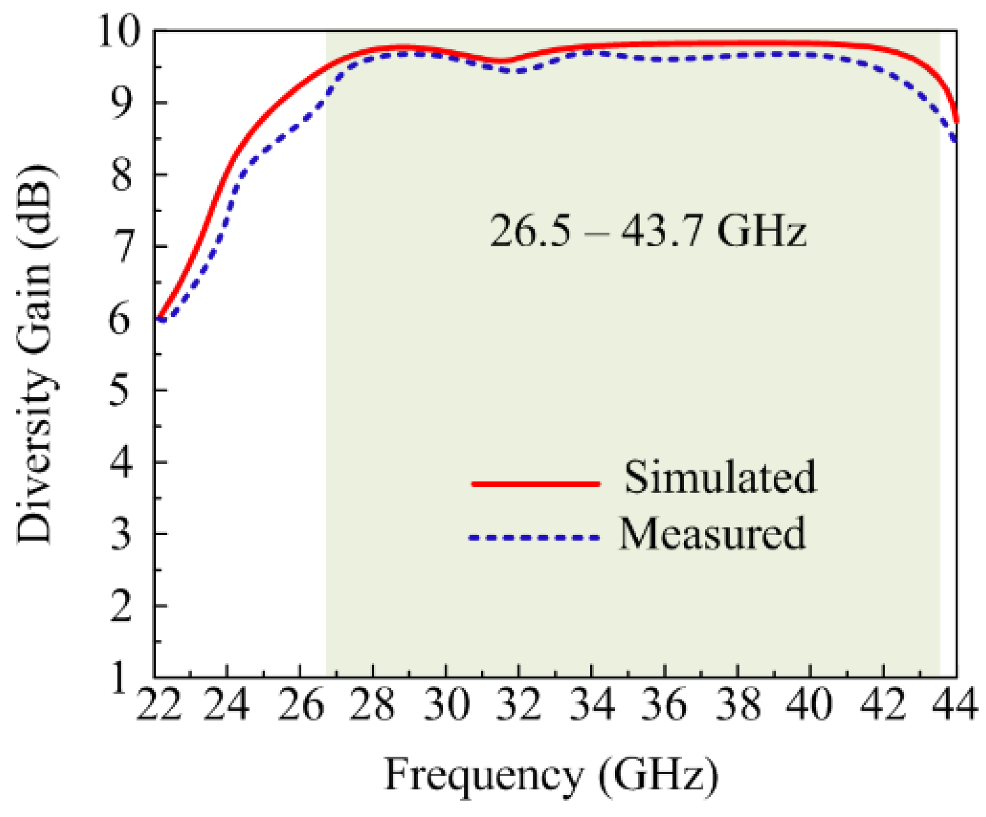
3.2.5. Diversity Gain
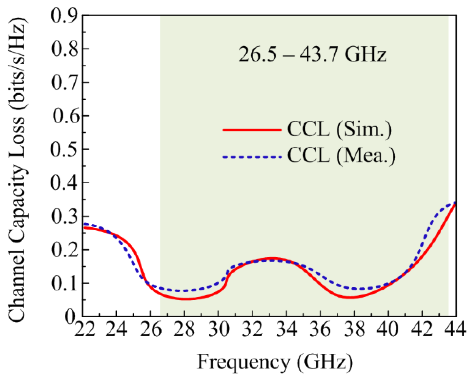
3.2.6. Channel Capacity Loss
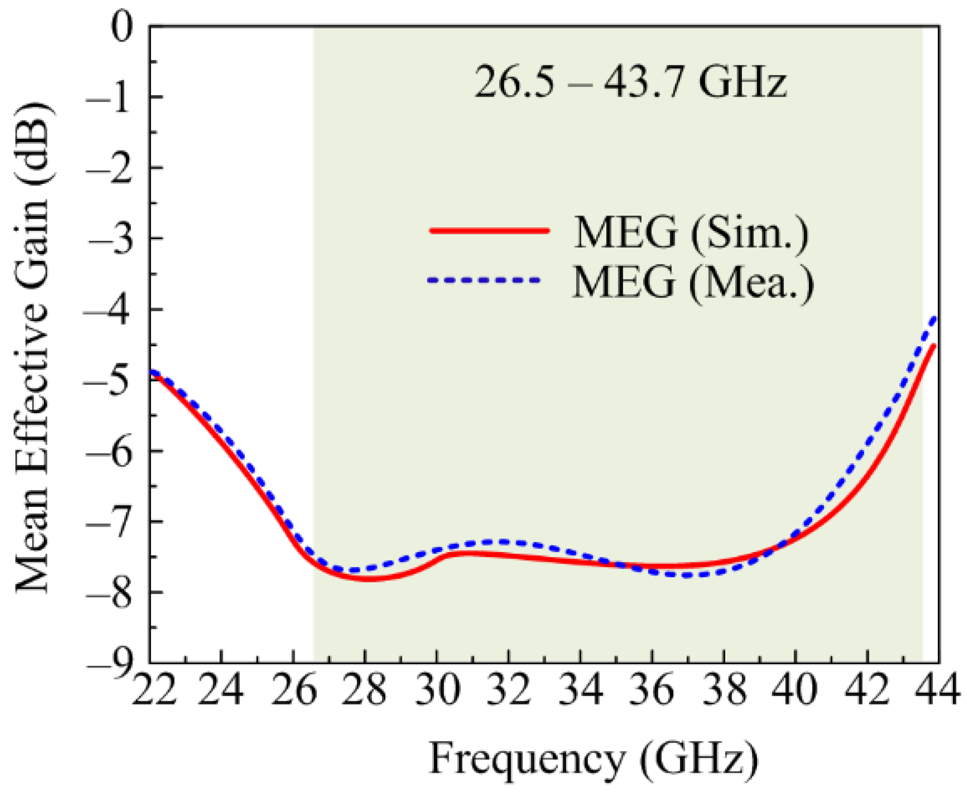
3.2.7. Mean Effective Gain
3.3. Performance Comparison
4. Conclusions
Author Contributions
Funding
Institutional Review Board Statement
Informed Consent Statement
Data Availability Statement
Acknowledgments
Conflicts of Interest
References
- Rappaport, T.S.; Sun, S.; Mayzus, R.; Zhao, H.; Azar, Y.; Wang, K.; Wong, G.N.; Schulz, J.K.; Samimi, M.; Gutierrez, F. Millimeter wave mobile communications for 5G cellular: It will work! IEEE Access 2013, 1, 335–349. [Google Scholar] [CrossRef]
- Hussain, M.; Awan, W.A.; Alzaidi, M.S.; Hussain, N.; Ali, E.M.; Falcone, F. Metamaterials and their application in the performance enhancement of reconfigurable antennas: A review. Micromachines 2023, 14, 349. [Google Scholar] [CrossRef] [PubMed]
- Kulkarni, J.; Sim, C.Y.D.; Gangwar, R.K.; Anguera, J. Broadband and compact circularly polarized MIMO antenna with concentric rings and oval slots for 5G application. IEEE Access 2022, 10, 29925–29936. [Google Scholar] [CrossRef]
- Rosaline, I.; Kumar, A.; Upadhyay, P.; Murshed, A.H. Four element MIMO antenna systems with decoupling lines for high-speed 5G wireless data communication. Int. J. Antennas Propag. 2022, 2022, e9078929. [Google Scholar] [CrossRef]
- Hei, Y.Q.; He, J.G.; Li, W.T. Wideband Decoupled 8-Element MIMO Antenna for 5G Mobile Terminal Applications. IEEE Antennas Wirel. Propag. Lett. 2021, 20, 1448–1452. [Google Scholar] [CrossRef]
- Hussain, M.; Awan, W.A.; Ali, E.M.; Alzaidi, M.S.; Alsharef, M.; Elkamchouchi, D.H.; Alzahrani, A.; Fathy Abo Sree, M. Isolation improvement of parasitic element-loaded dual-band MIMO antenna for mm-Wave applications. Micromachines 2022, 13, 1918. [Google Scholar] [CrossRef]
- Ali, E.M.; Awan, W.A.; Naqvi, S.I.; Alzaidi, M.S.; Alzahrani, A.; Elkamchouchi, D.H.; Falcone, F.; Alharbi, T.E.A. A low-profile antenna for on-body and off-body applications in the lower and upper ISM and WLAN bands. Sensors 2023, 23, 709. [Google Scholar] [CrossRef]
- Tang, H.; Bulger, C.J.; Rovere, T.; Zheng, B.; An, S.; Li, H.; Dong, Y.; Haerinia, M.; Fowler, C.; Gonya, S.; et al. A Low-Profile Flexible Dual-Band Antenna with Quasi-Isotropic Radiation Patterns for MIMO System on UAVs. IEEE Antennas Wirel. Propag. Lett. 2022, 22, 49–53. [Google Scholar] [CrossRef]
- Affandi, A.; Azim, R.; Alam, M.M.; Islam, M.T. A low-profile wideband antenna for WWAN/LTE applications. Electronics 2020, 9, 393. [Google Scholar] [CrossRef] [Green Version]
- Zaidi, A.; Awan, W.A.; Ghaffar, A.; Alzaidi, M.S.; Alsharef, M.; Elkamchouchi, D.H.; Ghoneim, S.S.M.; Alharbi, T.E.A. A low profile ultra-wideband antenna with reconfigurable notch band characteristics for smart electronic systems. Micromachines 2022, 13, 1803. [Google Scholar] [CrossRef]
- Hussain, M.; Ali, E.M.; Awan, W.A.; Hussain, N.; Alibakhshikenari, M.; Virdee, B.S.; Falcone, F. Electronically reconfigurable and conformal triband antenna for wireless communications systems and portable devices. PLoS ONE 2022, 17, e0276922. [Google Scholar] [CrossRef] [PubMed]
- Hussain, M.; Hussain, A.; Alibakhshikenari, M.; Falcone, F.; Limiti, E. A simple geometrical frequency reconfigurable Antenna with Miniaturized Dimensions for 24.8/28GHz 5G Applications. In Proceedings of the 2022 16th European Conference on Antennas and Propagation (EuCAP), Madrid, Spain, 27 March–1 April 2022; pp. 1–3. [Google Scholar]
- Kamal, M.M.; Yang, S.; Kiani, S.H.; Sehrai, D.A.; Alibakhshikenari, M.; Abdullah, M.; Falcone, F.; Limiti, E.; Munir, M. A novel hook-shaped antenna operating at 28 GHz for future 5G mmwave applications. Electronics 2021, 10, 673. [Google Scholar] [CrossRef]
- Zahra, H.; Awan, W.A.; Ali, W.A.E.; Hussain, N.; Abbas, S.M.; Mukhopadhyay, S. A 28 GHz Broadband Helical Inspired End-Fire Antenna and Its MIMO Configuration for 5G Pattern Diversity Applications. Electronics 2021, 10, 405. [Google Scholar] [CrossRef]
- Ibrahim, A.A.; Zahra, H.; Dardeer, O.M.; Hussain, N.; Abbas, S.M.; Abdelghany, M.A. Slotted Antenna Array with Enhanced Radiation Characteristics for 5G 28 GHz Communications. Electronics 2022, 11, 2664. [Google Scholar] [CrossRef]
- Ullah, H.; Abutarboush, H.F.; Rashid, A.; Tahir, F.A. A Compact Low-Profile Antenna for Millimeter-Wave 5G Mobile Phones. Electronics 2022, 11, 3256. [Google Scholar] [CrossRef]
- Kumar, P.; Ali, T.; Kumar, O.P.; Vincent, S.; Kumar, P.; Nanjappa, Y.; Pathan, S. An Ultra-Compact 28 GHz Arc-Shaped Millimeter-Wave Antenna for 5G Application. Micromachines 2023, 14, 5. [Google Scholar] [CrossRef]
- Ikram, M.; Sharawi, M.S.; Shamim, A. A novel very wideband integrated antenna system for 4G and 5G mm-wave applications. Microw. Opt. Technol. Lett. 2017, 59, 3082–3088. [Google Scholar] [CrossRef]
- Jilani, S.F.; Abbasi, Q.H.; Imran, M.A.; Alomainy, A. Design and Analysis of Millimeter-Wave Antennas for the Fifth Generation Networks and Beyond. In Wiley 5G Ref: The Essential 5G Reference Online; Wiley Online Library: New York, NY, USA, 2019; pp. 1–21. [Google Scholar]
- Tu, D.T.T.; Thang, N.G.; Ngoc, N.T.; Phuong, N.T.B.; Van Yem, V. 28/38 GHz dual-band MIMO antenna with low mutual coupling using novel round patch EBG cell for 5G applications. In Proceedings of the International Conference on Advanced Technologies for Communications (ATC), Quy Nhon, Vietnam, 18–20 October 2017; pp. 64–69. [Google Scholar]
- Xing, H.; Wang, X.; Gao, Z.; An, X.; Zheng, H.-x.; Wang, M.; Li, E. Efficient Isolation of an MIMO Antenna Using Defected Ground Structure. Electronics 2020, 9, 1265. [Google Scholar] [CrossRef]
- Abdullah, M.; Kiani, S.H.; Iqbal, A. Eight element multiple-input multiple-output (MIMO) antenna for 5G mobile applications. IEEE Access 2019, 7, 134488–134495. [Google Scholar] [CrossRef]
- Desai, A.; Bui, C.D.; Patel, J.; Upadhyaya, T.; Byun, G.; Nguyen, T.K. Compact wideband four element optically transparent MIMO antenna for mm-wave 5G applications. IEEE Access 2020, 8, 194206–194217. [Google Scholar] [CrossRef]
- Saad, A.A.R.; Mohamed, H.A. Printed millimeter-wave MIMO-based slot antenna arrays for 5G networks. AEU Int. J. Electron. Commun. 2019, 99, 59–69. [Google Scholar] [CrossRef]
- Marzouk, H.M.; Ahmed, M.I.; Shaalan, A.A. A Novel Dual-Band 28/38 GHz AFSL MIMO Antenna for 5G Smartphone Applications; Journal of Physics: Conference Series; IOP Publishing: Bristol, UK, 2020; Volume 1447. [Google Scholar]
- Elfergani, I.; Rodriguez, J.; Iqbal, A.; Sajedin, M.; Zebiri, C.; AbdAlhameed, R.A. Compact millimeter-wave MIMO antenna for 5G applications. In Proceedings of the 14th European Conference on Antennas and Propagation (EuCAP), Copenhagen, Denmark, 15–20 March 2020; pp. 1–5. [Google Scholar]
- Alreshaid, A.T.; Hussain, R.; Podilchak, S.K.; Sharawi, M.S. A dual-element MIMO antenna system with a mm-wave antenna array. In Proceedings of the 2016 10th European conference on antennas and propagation (EuCAP), Davos, Switzerland, 10–15 April 2016; pp. 1–4. [Google Scholar]
- Arabi, O.; See, C.H.; Ullah, A.; Ali, N.; Liu, B.; Abd-Alhameed, R.; McEwan, N.J.; Excell, P.S. Compact Wideband MIMO Diversity Antenna for Mobile Applications Using Multi-Layered Structure. Electronics 2020, 9, 1307. [Google Scholar] [CrossRef]
- Wani, Z.; Abegaonkar, M.P.; Koul, S.K. A 28-GHz antenna for 5G MIMO applications. Prog. Electromagn. Res. Lett. 2018, 78, 73–79. [Google Scholar] [CrossRef] [Green Version]
- Sehrai, D.A.; Abdullah, M.; Altaf, A.; Kiani, S.H.; Muhammad, F.; Tufail, M.; Irfan, M.; Glowacz, A.; Rahman, S. A novel high gain wideband MIMO antenna for 5G millimeter wave applications. Electronics 2020, 9, 1031. [Google Scholar] [CrossRef]
- Taher, F.; Hamadi, H.A.; Alzaidi, M.S.; Alhumyani, H.; Elkamchouchi, D.H.; Elkamshoushy, Y.H.; Haweel, M.T.; Sree, M.F.A.; Fatah, S.Y.A. Design and analysis of circular polarized two-port MIMO antennas with various antenna element orientations. Micromachines 2023, 14, 380. [Google Scholar] [CrossRef]
- Dayo, Z.A.; Aamir, M.; Rahman, Z.; Khoso, I.A.; Lodro, M.M.; Dayo, S.A.; Soothar, P.; Pathan, M.S.; Al-Gburi, A.J.A.; Memon, A.A.; et al. A Novel Low-Cost Compact High-Performance Flower-Shaped Radiator Design for Modern Smartphone Applications. Micromachines 2023, 14, 463. [Google Scholar] [CrossRef] [PubMed]
- Saeidi, T.; Al-Gburi, A.J.A.; Karamzadeh, S. A Miniaturized Full-Ground Dual-Band MIMO Spiral Button Wearable Antenna for 5G and Sub-6 GHz Communications. Sensors 2023, 23, 1997. [Google Scholar] [CrossRef]
- Khan, A.; He, Y.; He, Z.; Chen, Z.N. A Compact Quadruple-Band Circular Polarized MIMO Antenna With Low Mutual Coupling. IEEE Trans. Circuits Syst. II Express Briefs 2023, 70, 501–505. [Google Scholar] [CrossRef]
- Liu, J.; Liu, H.; Dou, X.; Tang, Y.; Zhang, C.; Wang, L.; Tang, R.; Yin, Y. A low profile, dual-band, dual-polarized patch antenna with antenna-filter functions and its application in MIMO systems. IEEE Access 2021, 9, 101164–101171. [Google Scholar] [CrossRef]
- Khan, A.; He, Y.; Chen, Z.N. An Eight-Port Circularly Polarized Wideband MIMO Antenna Based on a Metamaterial-Inspired Element for 5G mmWave Applications. IEEE Antennas Wirel. Propag. Lett. 2023. [Google Scholar] [CrossRef]
- Ali, W.A.E.; Ibrahim, R.A. Highly Compact 4 × 4 Flower-Shaped MIMO Antenna for Wideband Communications. Appl. Sci. 2023, 13, 3532. [Google Scholar] [CrossRef]
- Wong, K.L.; Jian, M.F.; Li, W.Y. Low-profile wideband four-corner-fed square patch antenna for 5G MIMO mobile antenna application. IEEE Antennas Wirel. Propag. Lett. 2021, 20, 2554–2558. [Google Scholar] [CrossRef]
- Chattha, H.T.; Ishfaq, M.K.; Khawaja, B.A.; Sharif, A.; Sheriff, N. Compact multiport MIMO antenna system for 5G IoT and cellular handheld applications. IEEE Antennas Wirel. Propag. Lett. 2021, 20, 2136–2140. [Google Scholar] [CrossRef]
- Din, I.U.; Kiyani, A.; Naqvi, S.I.; Al-Gburi, A.J.A.; Abbas, S.M.; Ullah, S. A Low-Cost Wideband MIMO Antenna for IoT Applications. In Proceedings of the 2022 IEEE International Symposium on Antennas and Propagation and USNC-URSI Radio Science Meeting (AP-S/URSI), Denver, CO, USA, 10–15 July 2022; pp. 2064–2065. [Google Scholar] [CrossRef]
- Jehangir, S.S.; Sharawi, M.S. A compact single-layer four-port orthogonally polarized Yagi-like MIMO antenna system. IEEE Antennas Wirel. Propag. Lett. 2020, 68, 6372–6377. [Google Scholar] [CrossRef]
- Hussain, M.; Mousa Ali, E.; Jarchavi, S.M.R.; Zaidi, A.; Najam, A.I.; Alotaibi, A.A.; Althobaiti, A.; Ghoneim, S.S.M. Design and characterization of compact broadband antenna and its MIMO configuration for 28 GHz 5G applications. Electronics 2022, 11, 523. [Google Scholar] [CrossRef]
- Dayo, Z.A.; Aamir, M.; Dayo, S.A.; Khoso, I.A.; Soothar, P.; Sahito, F.; Zheng, T.; Hu, Z.; Guan, Y. A novel compact broadband and radiation efficient antenna design for medical IoT healthcare system. Math. Biosci. Eng. 2022, 19, 3909–3927. [Google Scholar] [CrossRef]
- Dama, Y.A.S.; Abd-Alhameed, R.A.; Jones, S.M.R.; Zhou, D.; McEwan, N.J.; Child, M.B.; Excell, P.S. An envelope correlation formula for (N, N) MIMO antenna arrays using input scattering parameters, and including power losses. Int. J. Antennas Propag. 2011, 2011, 421691. [Google Scholar] [CrossRef] [Green Version]
- Hussain, N.; Awan, W.A.; Ali, W.; Naqvi, S.I.; Zaidi, A.; Le, T.T. Compact wideband patch antenna and its MIMO configuration for 28 GHz applications. AEU Int. J. Electron. Commun. 2021, 132, 153612. [Google Scholar] [CrossRef]
- Cai, J.; Zhang, J.; Xi, S.; Huang, J.; Liu, G. A Wideband Eight-Element Antenna with High Isolation for 5G New-Radio Applications. Appl. Sci. 2023, 13, 137. [Google Scholar] [CrossRef]


| Ref | Dimensions (mm × mm × mm) | Ports | Bandwidth (GHz) | Operating Frequency (GHz) | Peak Gain (dBi) | ECC | Mini. Isolation (dB) | Max. Isolation (dB) | MIMO Antenna Type |
|---|---|---|---|---|---|---|---|---|---|
| [18] | 115 × 60 × 0.76 | 5 | 27.5–28.7 | 28.3 | 5 | 0.056 | −30 | −13 | Monopole antenna |
| [19] | 50.8 × 12.5 × 0.8 | 4 | 26–36 | 27 | 5.23 | – | −45 | −22 | CPW-fed patch antenna |
| [20] | 19.25 × 26 × 0.79 | 4 | 27–30.5 | 28.5 | 7.58 | 0.001 | −35 | −12 | EBG-based antenna |
| [23] | 24 × 20 × 1.85 | 4 | 33–44.1 | 38 | 4.56 | 0.1 | −32 | −16 | Patch antenna over transparent substrate |
| [24] | 53 × 20 × 0.203 | 2 | 22–50 | 36/45 | 15 | 0.12 | −40 | −20 | Slot array antenna |
| [25] | 110 × 55 × 1.6 | 6 | 27.7–28.7 | 28 | 5.13 | 0.005 | −55 | −22 | Air-filled slotted loop (AFSL) antenna |
| [26] | 12.5 × 12.5 × 0.8 | 4 | 33–36 | 35 | 6 | 0.02 | −33 | −23 | Hexagonal patch antenna |
| [27] | 60 × 100 × 0.965 | 2 | 27.6–28.3 | 28 | 4.5 | 0.134 | −30 | −17 | Modified monopole antenna |
| [29] | 48 × 31 × 0.254 | 4 | 26–31 | 28 | 10 | 0.0015 | −38 | −21 | Patch antenna loaded with array of meatmaterials |
| [30] | 80 × 80 × 1.57 | 4 | 23–40 | 30 | 12 | 0.0014 | −40 | −20 | Arc-shaped patch antenna |
| [31] | 20.5 × 12 × 0.79 | 2 | 25.5–30 | 28 | 8.75 | – | −40 | −30 | E-shaped patch antenna |
| Prop. Work | 27 × 27 × 1.52 | 4 | 26.5–43.7 | 30/38 | 8.4 | 0.001 | −42 | −30 | Stub loaded monopole antenna |
Disclaimer/Publisher’s Note: The statements, opinions and data contained in all publications are solely those of the individual author(s) and contributor(s) and not of MDPI and/or the editor(s). MDPI and/or the editor(s) disclaim responsibility for any injury to people or property resulting from any ideas, methods, instructions or products referred to in the content. |
© 2023 by the authors. Licensee MDPI, Basel, Switzerland. This article is an open access article distributed under the terms and conditions of the Creative Commons Attribution (CC BY) license (https://creativecommons.org/licenses/by/4.0/).
Share and Cite
Hussain, S.A.; Taher, F.; Alzaidi, M.S.; Hussain, I.; Ghoniem, R.M.; Sree, M.F.A.; Lalbakhsh, A. Wideband, High-Gain, and Compact Four-Port MIMO Antenna for Future 5G Devices Operating over Ka-Band Spectrum. Appl. Sci. 2023, 13, 4380. https://0-doi-org.brum.beds.ac.uk/10.3390/app13074380
Hussain SA, Taher F, Alzaidi MS, Hussain I, Ghoniem RM, Sree MFA, Lalbakhsh A. Wideband, High-Gain, and Compact Four-Port MIMO Antenna for Future 5G Devices Operating over Ka-Band Spectrum. Applied Sciences. 2023; 13(7):4380. https://0-doi-org.brum.beds.ac.uk/10.3390/app13074380
Chicago/Turabian StyleHussain, Sayed Aqib, Fatma Taher, Mohammed S. Alzaidi, Irshad Hussain, Rania M. Ghoniem, Mohamed Fathy Abo Sree, and Ali Lalbakhsh. 2023. "Wideband, High-Gain, and Compact Four-Port MIMO Antenna for Future 5G Devices Operating over Ka-Band Spectrum" Applied Sciences 13, no. 7: 4380. https://0-doi-org.brum.beds.ac.uk/10.3390/app13074380