
A Compact Planar Wi-Fi Antenna with Optimized Radiation Patterns for Small UAV Applications


Department of Electronic and Computer Engineering, National Taiwan University of Science and Technology, Taipei 106335, Taiwan
*
Author to whom correspondence should be addressed.
Appl. Sci. 2023, 13(13), 7470; https://0-doi-org.brum.beds.ac.uk/10.3390/app13137470
Submission received: 19 May 2023
/
Revised: 16 June 2023
/
Accepted: 22 June 2023
/
Published: 24 June 2023
(This article belongs to the Special Issue Design, Analysis, and Measurement of Antennas)
Abstract
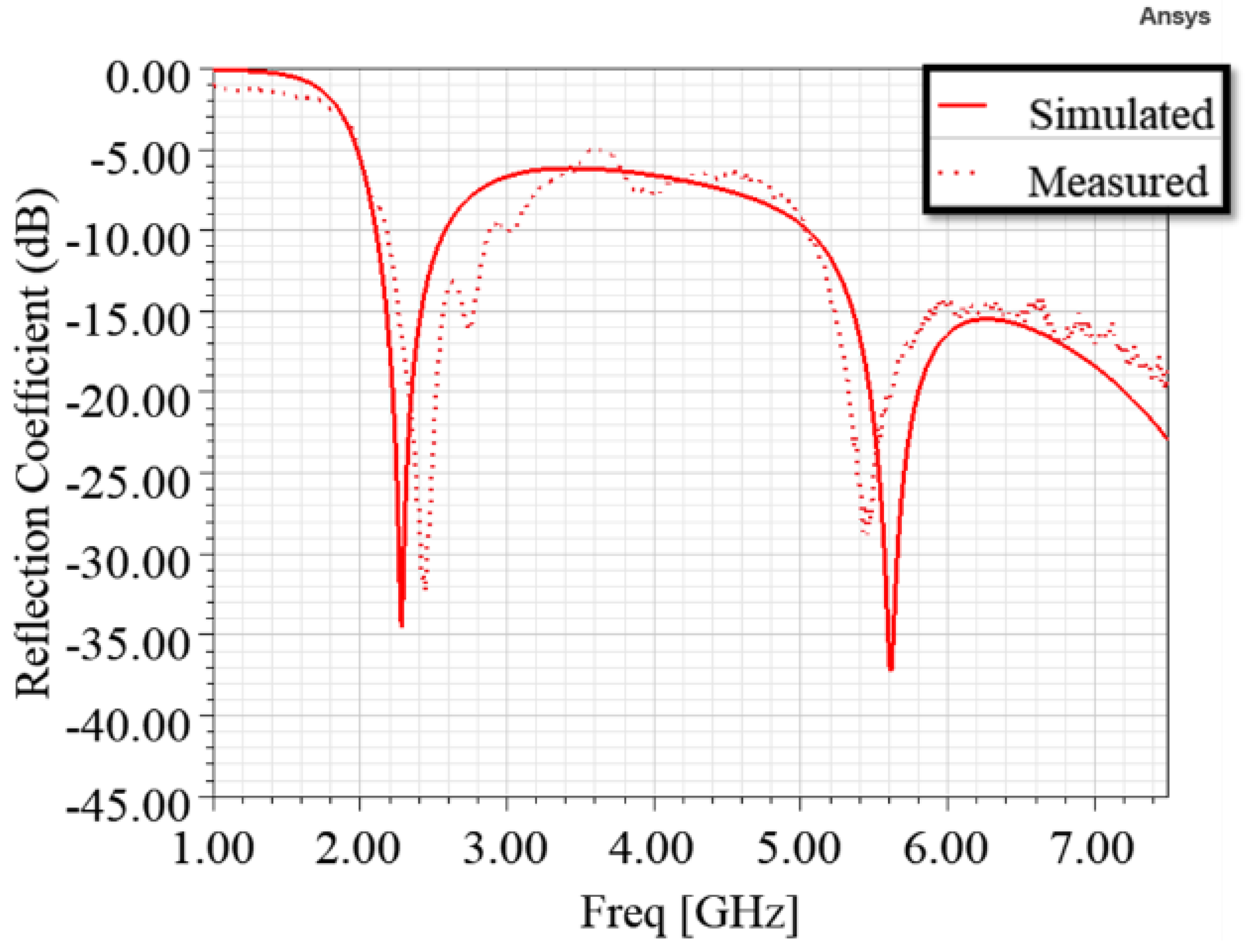
:This paper proposes a compact planar Wi-Fi antenna with optimized radiation patterns for small uncrewed aerial vehicle (UAV) applications in both urban and open areas. It is suitable for mounting on the outermost side of the non-metallic wing of small UAVs. It has small dimensions of 16.5 mm (L) by 30.3 mm (W) by 1.6 mm (h), and the measured results of its prototype are in agreement with simulated data. Its impedance bandwidths over the two frequency ranges are 2.11 to 2.58 GHz and 5.06 to 7.5 GHz (). At 5.8 GHz, it has stronger radiation below the small UAV to reduce interference from rare-use directions. Its maximum radiations, the directions of the maximum radiation in each elevation plane, are below the UAV and between 14° and 29° from the horizontal plane. At 2.4 GHz, it has quasi-omnidirectional radiation to ensure a stable link in all directions, and its maximum radiations are near the horizontal plane. The optimized radiation patterns at 5.8 and 2.4 GHz can provide more antenna gain when the small UAV flies farther in urban and open areas, respectively. In addition, it has good vertically polarized radiation for long-distance applications.
1. Introduction
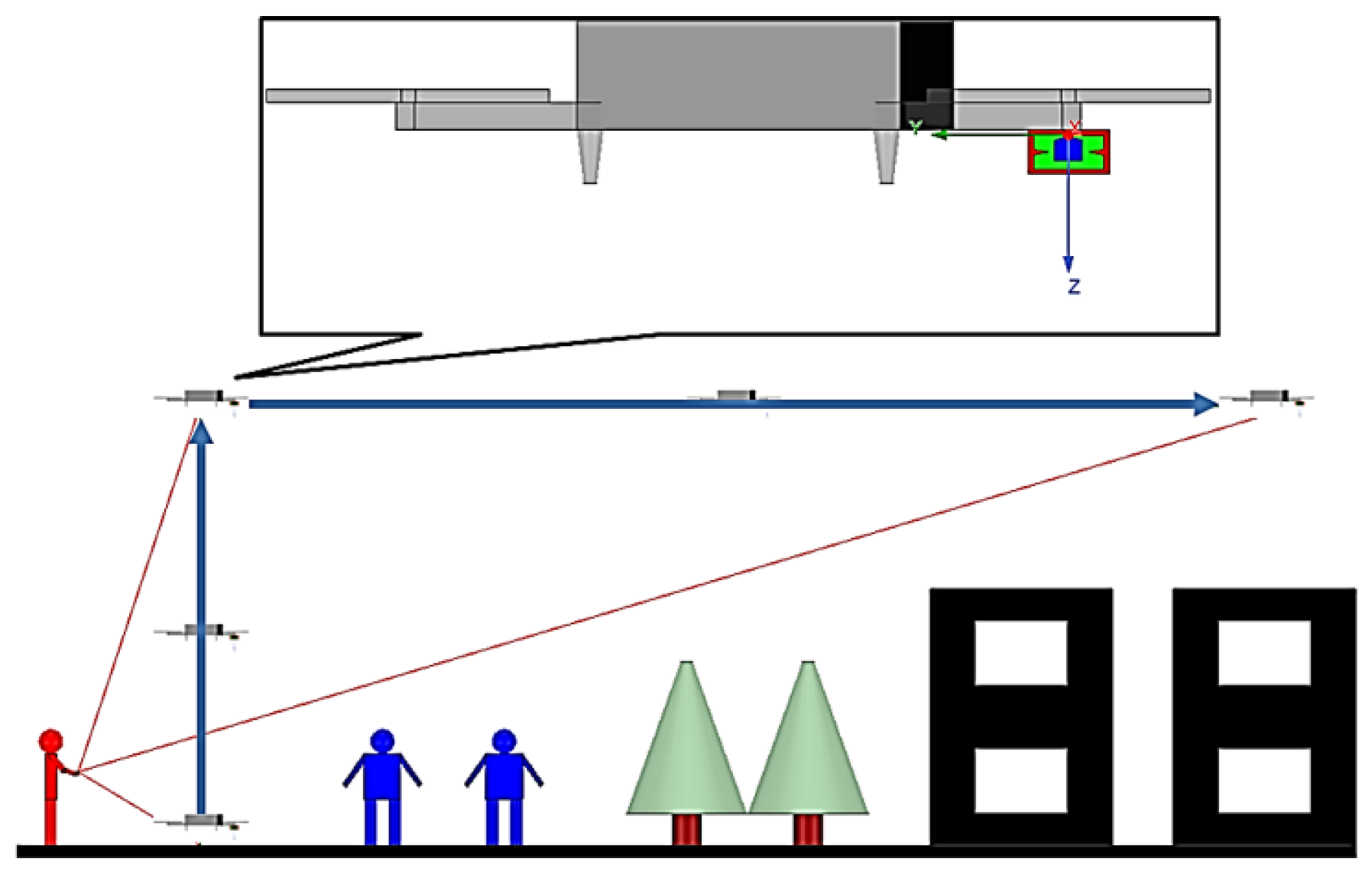
With the rapid increase in the number of small uncrewed aircraft vehicles (UAVs), their antenna design is becoming increasingly important to ensure a stable link [1]. This study addresses an antenna design for light-and-small civil UAV applications in urban areas. Small UAVs tend to be lightweight and small for portability, so they are unsuitable for mounting turntables or large phased-array antennas. Figure 1 shows the common scenarios of light-and-small civil UAV applications in urban areas where a person holding a remote control operates a quadcopter.
The proposed antenna is mounted below the propeller on the outermost side of the wing of a small UAV, away from large metal conductors, such as printed circuit boards (PCBs) and batteries, in the UAV body. The UAV takes off from the ground, flies vertically above ground objects, and then flies forward to the farthest position. The flight must avoid hitting ground objects, such as people, trees, and buildings, so the UAV must stay above them. The distance between the UAV and the remote control increases as it takes off from the ground, flies vertically above ground objects, and flies forward to the farthest position.
To ensure stable transmission quality and stability, the gain and polarization characteristics of the antenna are determined based on the Friis transmission equation [2]. The antenna must meet the following requirements to reduce interference and provide more antenna gain when the small UAV flies farther in urban areas. First, its must be equal to or smaller than to ensure efficient power delivery to the antenna. Second, it must have a small size and low profile to meet the portability and aerodynamic requirements for small UAV applications. Third, it must have stronger radiation below the UAV to reduce interference from rare-use directions. Given that the UAV is always above the remote control as it flies away, it is farther away from the remote control than when it was taking off. Fourth, its maximum radiations, the directions of the maximum radiation in each elevation plane, must be below the UAV and between 10° and 30° from the horizontal plane to provide more antenna gain when the small UAV flies farther in urban areas. Finally, due to the boundary condition of the earth’s ground plane, the antenna must have good vertically polarized radiation for long-distance applications.
Although many antenna architectures have been proposed [3,4,5,6,7,8,9,10,11,12,13,14] to meet the requirements for UAV applications, none fully meet the requirements for small UAV applications in urban areas. Due to their small size and lightweight nature, folded dipole antennas have been proposed [3,4] for small and compact UAV applications, respectively. The fragmented antenna was proposed [3], and its overall dimensions and total mass are at 240 MHz and 18 g (including the matching circuit). A compact electrically tunable VHF antenna [4] was integrated into the landing gear of a compact UAV with good vertically polarized radiation. However, neither of them has stronger radiation below the UAV, and their maximum radiations are near the horizontal plane. In addition, both of them need an extra matching circuit to match their characteristic impedance to 50 for a better reflection coefficient at the operation frequency. The low-profile, quasi-omnidirectional substrate-integrated waveguide (SIW) multi-horn antenna was proposed [5] for small non-metallic UAV applications. It has good vertically polarized radiation and a low profile of 0.028 at 2.4 GHz. However, it does not have stronger radiation below the UAV, and its lateral dimensions of are too large for small UAVs. Due to their low profile and ability to conform to planar and nonplanar surfaces, patch antennas were proposed [6,7] for UAV applications. The high-gain dual-mode cylindrical conformal rectangular patch antenna [6] has a low profile of 0.508 mm (0.0175 at 10.323 GHz), stronger radiation below the quadcopter UAV, and good vertically polarized radiation. The required radius of the arm of the UAV is 25 mm at the lowest operating frequency of 10.288 GHz, and three patch antennas are needed on the UAV arm to cover the hemisphere below the UAV. The conformal patch antennas [7] have a low profile of 3 mm (0.058 at 5.8 GHz) and stronger radiation below the UAV. However, their maximum radiations are directly above each patch. Both models proposed multiple patch antennas on the UAV to ensure a stable link in the required directions. However, it takes up too much surface area, making them unsuitable for small UAVs. The design of a combined printed helical spiral antenna and helical inverted F antenna [8] was miniaturized by co-winding the radiation elements on the same ceramic rod with a height of 24.7 mm (0.129 at 1.57 GHz) and a radius of 6 mm. It was proposed for UAVs with a global positioning system (GPS) L1 band and telemetry communication frequency band (2.33 GHz) applications. However, it does not have stronger radiation below the UAV at 2.33 GHz. The low-profile broadband plasma antenna [9] has different radiation patterns at different operating frequencies and a low profile of 0.105 at 30 MHz. Its radiation pattern is omnidirectional at 30 MHz and stronger radiation below the UAV at 300 and 500 MHz. However, it must be matched with extra Butterworth low-pass and high-pass filters to isolate the 13.56 MHz radio frequency signal to activate plasma. Its complex structure and the need to use special materials such as plasma will result in a heavier weight and higher cost, making it unsuitable for small UAVs. The broadband slotted blade dipole antenna [10] radiation patterns vary at different operating frequencies. However, it must be matched with a special matching circuit and does not have stronger radiation below the UAV. In addition, its radiation patterns at all operating frequencies have nulls near the horizontal plane, causing the smallest gain when the UAV flies to the farthest position. Due to the advantages of simple structure and low manufacturing cost using modern printed circuit technology, printed planar antennas were proposed [11,12,13] for UAV applications. The planar dual-mode dipole antenna [11] has a short electrical length of 0.3297 at 0.86 GHz and good vertically polarized radiation. The omnidirectional vertically polarized antenna [12] also has good vertically polarized radiation and varying radiation patterns at different operating frequencies. However, neither has stronger radiation below the UAV, and their maximum radiations are near the horizontal plane. The wideband single-sided folded-off-center-fed dipole antenna [13] has good vertically polarized radiation and different radiation patterns at different operating frequencies. At 5 and 5.5 GHz, it has stronger radiation below the small UAV, and its maximum radiations are below the UAV and between 10° and 30° from the horizontal plane. At 3.5 GHz, it has quasi-omnidirectional radiation, and its maximum radiations are near the horizontal plane. However, its electrical length of 0.469 is too long for small UAV applications. A compact slot coplanar waveguide-fed antenna [14] was not proposed for small UAV applications and has a very short electrical length of and a low profile of to meet the portability and aerodynamic requirements for small UAV applications. However, it does not have stronger radiation below the UAV, and its maximum radiations are near the horizontal plane.
Summarizing the above literature review, most proposed antennas have maximum radiations near the horizontal plane for UAV applications. This feature can meet the requirements for UAV applications in open areas and provide more antenna gain when the small UAV flies farther. The wideband single-sided folded-off-center-fed dipole antenna [13] is the best; it has suitable radiation patterns to meet the requirements for small UAV applications in urban and open areas. In addition, it also has the advantage of a simple and cost-efficient structure, which can make light and small civil UAVs more affordable. However, its electrical length of 0.469 at 3.5 GHz is too long to meet the portability and aerodynamic requirements for small UAV applications.
This paper proposes a dual-band antenna with optimized radiation patterns for small UAV applications in urban and open areas. It has a shorter electrical length than the best one proposed: 0.132 at 2.4 GHz [13]. First, this study considers that the small UAV has a camera function and needs to transmit real-time images to the remote control for the user to preview or store. To meet this requirement, Wi-Fi 2.4 GHz and 5.8 GHz were selected as the operating frequencies. Secondly, since many technologies, such as Zigbee and Bluetooth, use 2.4 GHz as the operating frequency [15], there will be more interference at this frequency. Therefore, a quasi-directional radiation pattern was designed at 2.4 GHz, and its maximum radiations are near the horizontal plane for small UAV applications in open areas with less interference, such as mountains, oceans, or farmland. Third, an end-fire radiation pattern was designed at 5.8 GHz for small UAV applications in urban areas. It has stronger and maximum radiations below the UAV and between 14° and 29° from the horizontal plane. Finally, to ensure that the characteristics of this antenna will not be significantly affected when applied to small UAVs, the following assumptions are made in this study: First, as shown in Figure 1, the objects around the antenna, such as the UAV wing and propeller, must be made of non-metallic material. Second, the large metal conductors, such as PCBs and batteries, in the UAV body must be located in the far-field region of the proposed antenna. Based on the definition of the far-field region [16], the distance between the small UAV body and the proposed antenna must be > 46 mm.
By performing a theoretical analysis, full-wave simulation, and prototype measurement, we verified that the proposed antenna could meet the requirements for light and small civil UAV applications in urban and open areas. The rest of this paper is as follows: Section 2 presents the antenna design methodology, which includes the structural topology and theoretical analysis. Section 3 presents the parametric studies and full-wave simulations for validating the design theory. Section 4 presents the antenna prototype, measurement setup, comparisons of the simulated data, measured results of the prototype, and discussions about the results. Finally, Section 5 summarizes the results and future work.
2. Antenna Design and Analysis
In this study, a compact slot antenna with a coplanar waveguide (CPW) was designed that supports Wi-Fi dual-band communication and has a single-sided planar structure.
2.1. Antenna Structure and Main Design Steps
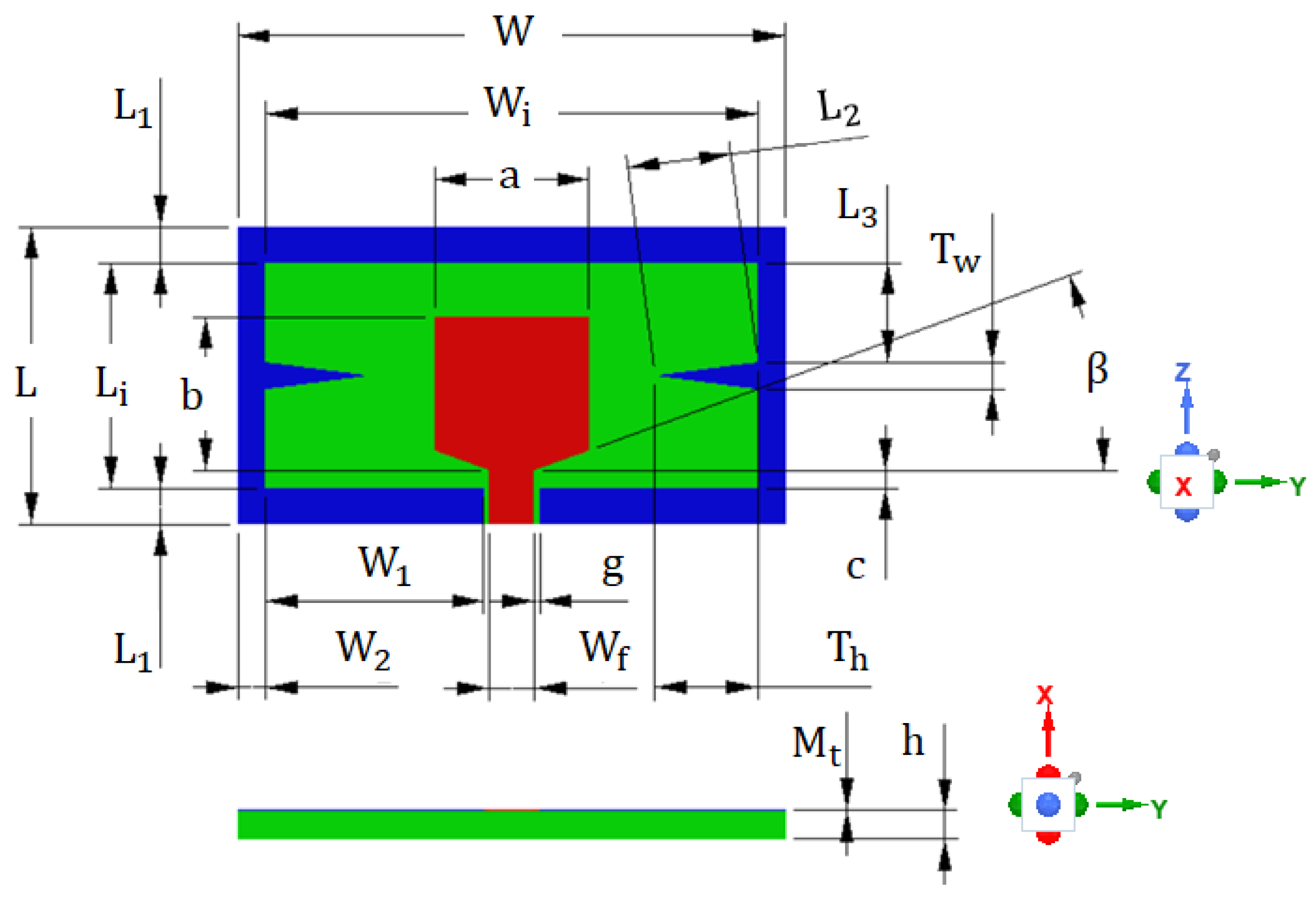
Figure 2 shows the structure of the proposed antenna with geometrical parameters. At 5.8 GHz, the four corners of its outer conductor are the primary radiation sources, forming end-fire radiation. At 2.4 GHz, the two sides of the outer conductor are the main effective radiation sources, forming quasi-omnidirectional radiation.
Table 1 displays the values of geometrical parameters for the proposed antenna. The thickness of the metal layer () is 0.035 mm, of which 0.031 mm is copper, 0.003 mm is nickel, and 0.001 mm is gold. It was printed on the FR4 substrate with a relative permittivity of 4.4, a loss tangent of 0.02, a thickness of 1.6 mm (h), and planar dimensions of 16.5 mm (L) by 30.3 mm (W). At the fed port, the width of the central conducting track () was 2.5 mm, and a pair of outer conducting tracks were separated from the central conducting track by a small gap (g) of 0.3 mm to achieve a characteristic impedance of 50 . The antenna was symmetrical on both sides of the x–z plane, so the radiation generated by the current components in the +y and −y directions would cancel out. Therefore, the currents in the +z and −z directions are the main radiation sources, providing the antenna with good vertically polarized radiation.
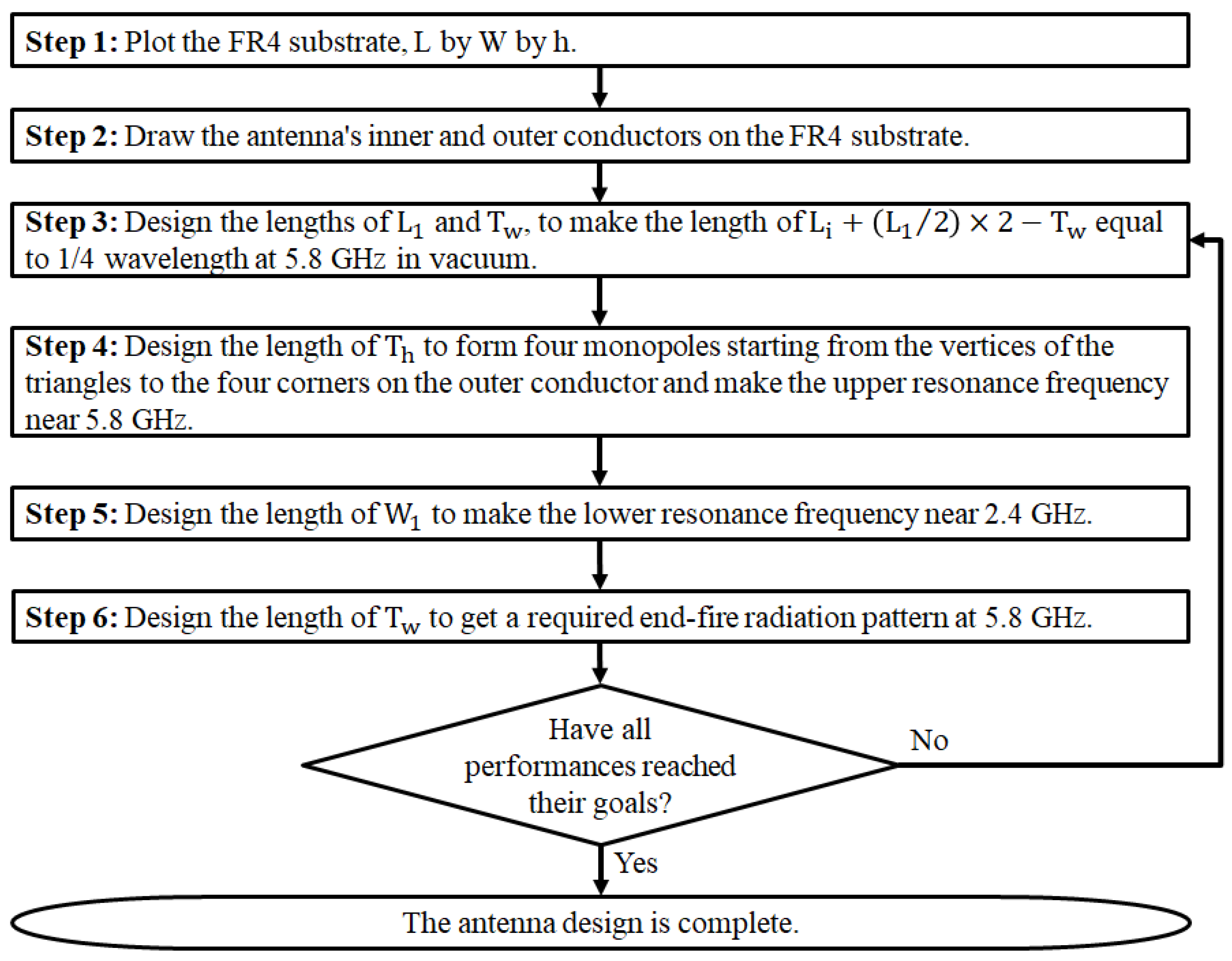
Figure 3 shows the main design steps of the proposed antenna. Steps 3 to 6 are the main design steps for key performances. The design theory is explained in detail in Section 2.1 and Section 2.2.
2.2. Antenna Design for 5.8 GHz
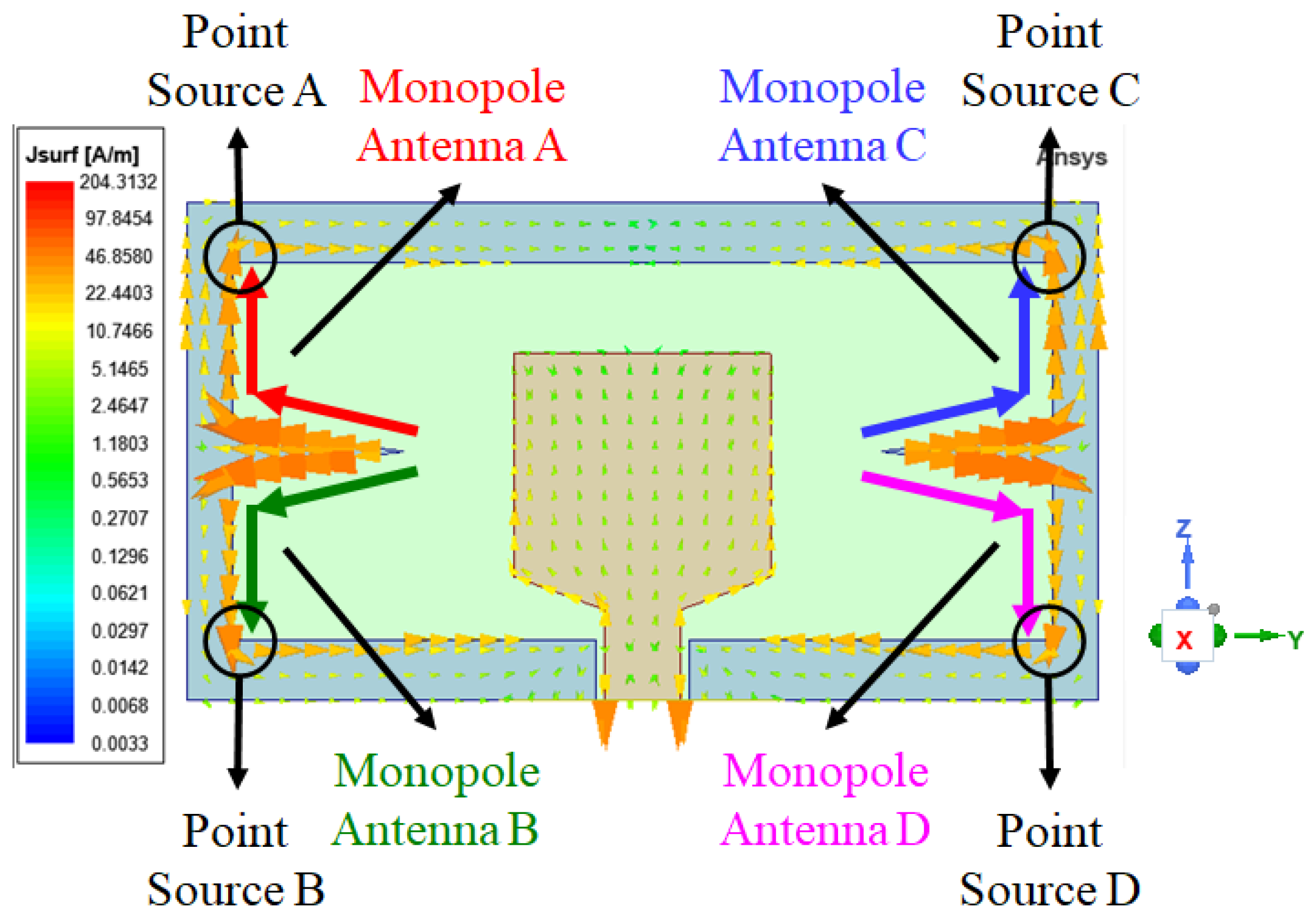
Figure 4 shows the simulated surface current density at 5.8 GHz, where the areas with higher surface current densities are the main radiation areas. The outer conductor forms four monopole antennas from each triangle vertex to its adjacent corners. These four monopoles have the same wavelength, , and the upper resonance frequency, , can be approximated using (1), where c is the speed of light in a vacuum ( m/s).
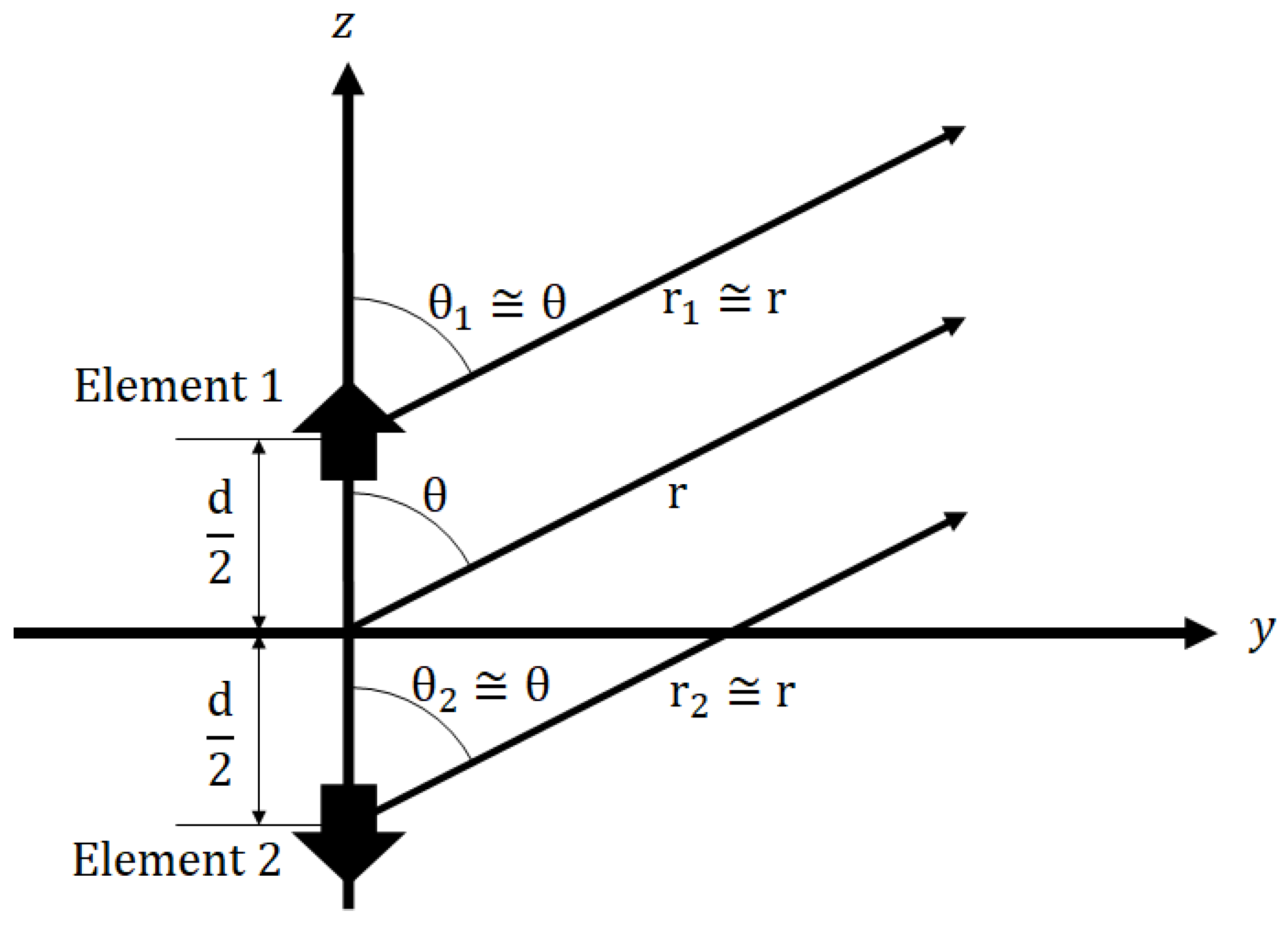
Higher surface current densities exist at the four corners inside the outer conductor, which approximate four point sources named Element A, Element B, Element C, and Element D. The radiation pattern is mainly synthesized from these four point sources. Due to the electric field that radiates between the inner and outer conductors, the proposed antenna approximates a two-element array of two point sources, Elements 1 and 2, as shown in Figure 5.
The radiation patterns of Elements 1 and 2 equal the sum of Elements A and C and the sum of Elements B and D, respectively. Furthermore, since the cross-sectional area of the inner conductor used as the reference plane is very small, the radiation patterns of Elements 1 and 2 approximate a vertical infinitesimal dipole. Based on the directivity of the vertical infinitesimal (Hertzian) dipole [17], the normalized pattern function of the vertical infinitesimal dipole is . The normalized array factor of Elements 1 and 2, , is adapted from (2) [18], where k is the wave number equal to , and d is the distance between Elements 1 and 2, approximately equal to . In addition, is the wavelength of 5.8 GHz in vacuum, is the elevation angle, and is the ratio of a circle’s circumference to its diameter ().
At 5.8 GHz, the difference in phase excitation, , can be derived by (3). Where , , , and are the phase excitations of Elements A, B, C, and D, respectively. In addition, equals , and the negative sign is the phase lag.
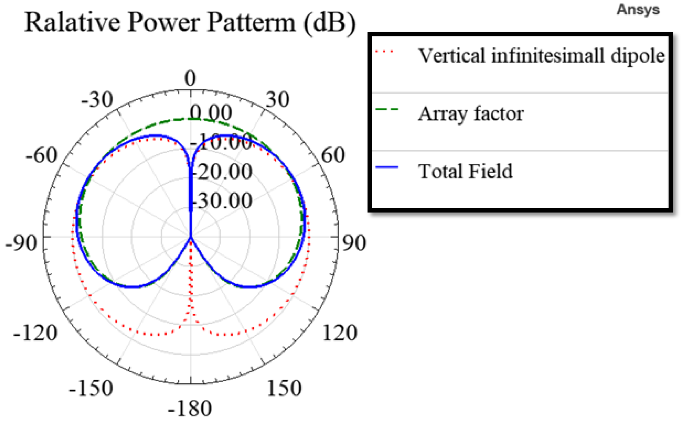
In (2), replacing with , the normalized array factor of Elements 1 and 2 can be written as (4). It has two maximums at and , only one minimum at , and forms an end-fire array toward .
The normalized total field of the two-element array antenna, , is (5). It has two maximums at and , only one minimum at , and forms an end-fire radiation toward .
Figure 6 shows the relative power patterns of the vertical infinitesimal dipole, the array factor of Elements 1 and 2, and the total field of the two-element array antenna.
2.3. Antenna Design for 2.4 GHz
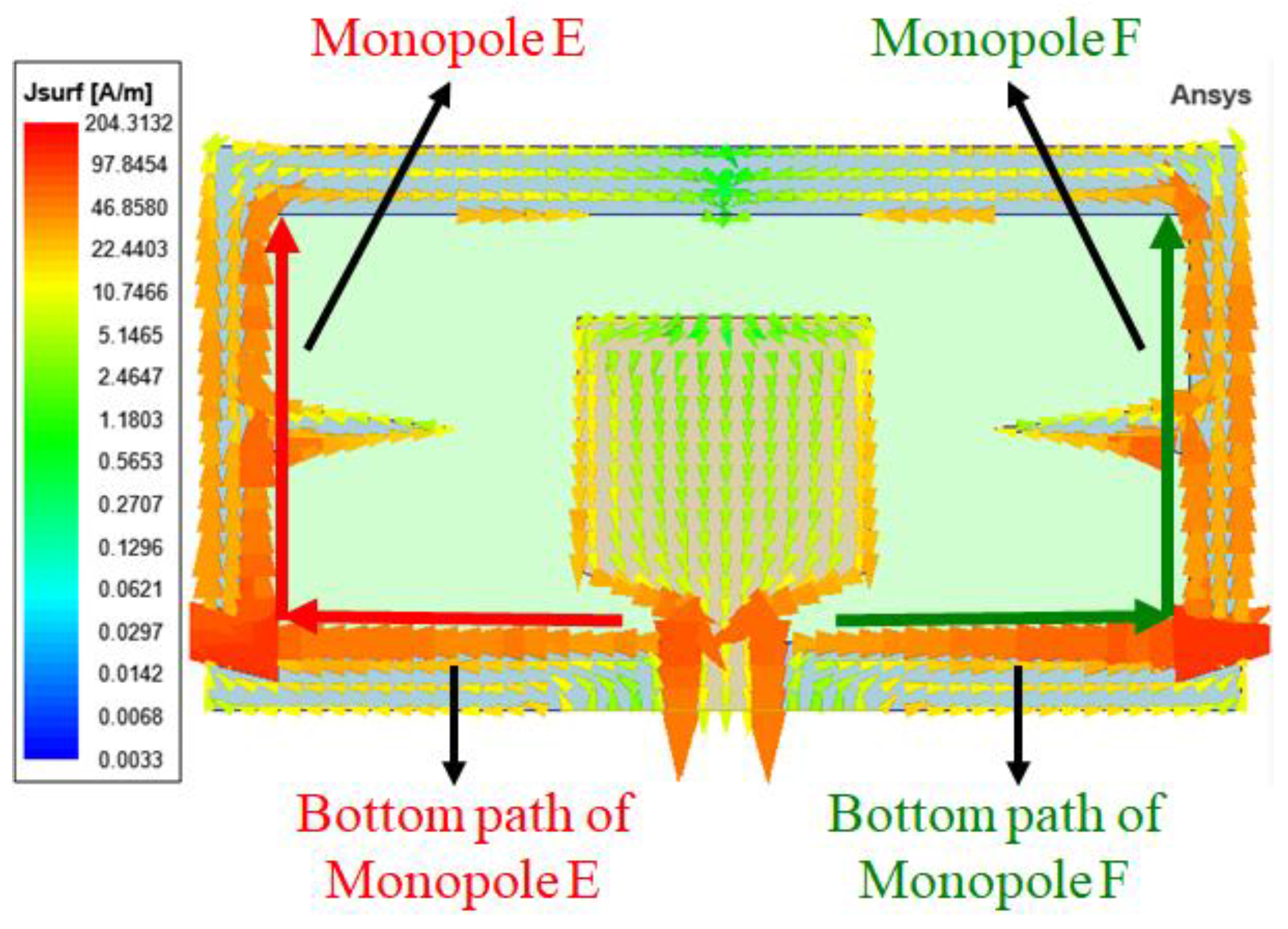
Figure 7 shows the simulated surface current densities at 2.4 GHz, where the areas with higher surface current densities are the main radiation areas. The two sides of the outer conductor form a pair of L-shaped monopoles, Monopoles E and F. These two monopoles have the same wavelength, , and the lower resonance frequency, , can be approximated by (6).
Due to the symmetrical design of the architecture, the radiations from the two bottom paths cancel each other out. Due to the electric field that radiates between the inner and outer conductors, the proposed antenna approximates a vertical monopole antenna. In addition, since the cross-sectional area of the inner conductor reference plane is very small, the radiation pattern of the vertical monopole antenna approximates a vertical dipole with an effective length of , equivalent to 0.122 . Its maximum radiations are near the horizontal plane.
3. Parametric Studies and Full-Wave Simulations
The proposed antenna was simulated by the ANSYS High-Frequency Structure Simulator (HFSS) [19]. From (1), decreases as increases, can be derived from (7), and increases as increases. Hence, decreases as increases.
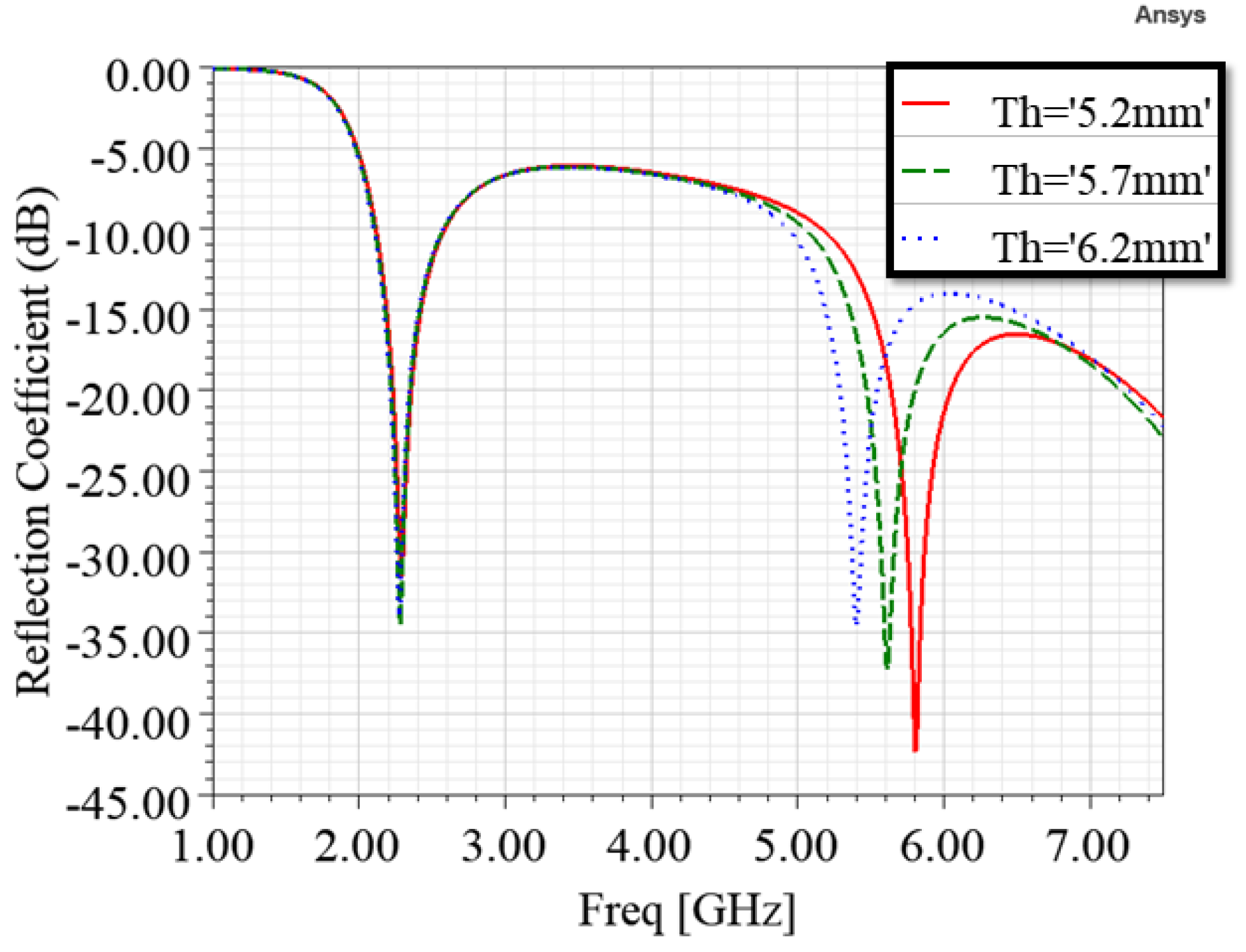
Figure 8 shows the simulated reflection coefficients for different values of . The simulated data agree with (1) and (7), decreases as increases, and is about 5.63 GHz when is 5.7 mm.
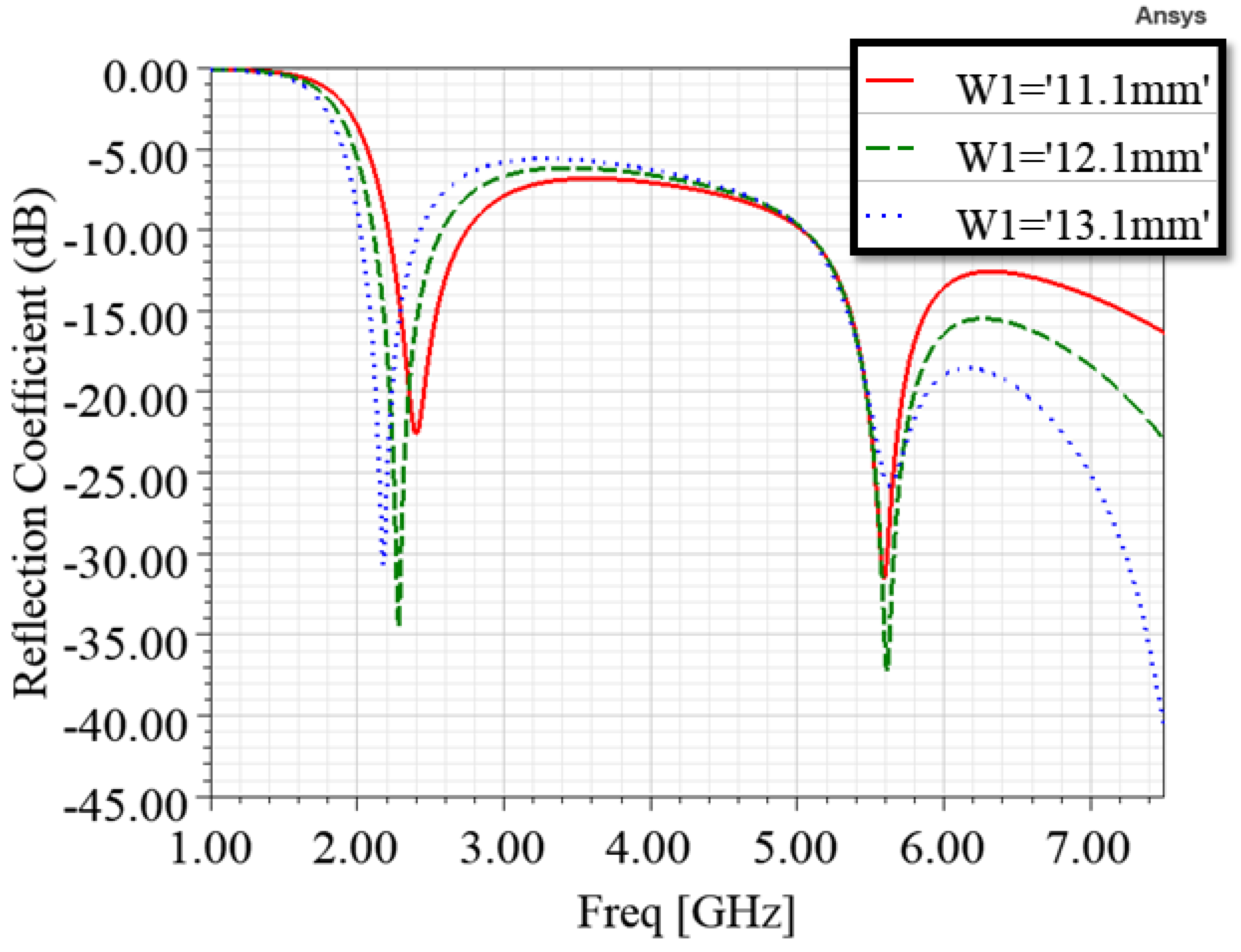
From (6), decreases as increases, and Figure 9 shows the simulated reflection coefficients for different values of . The simulated data agree with (6), decreases as increases.
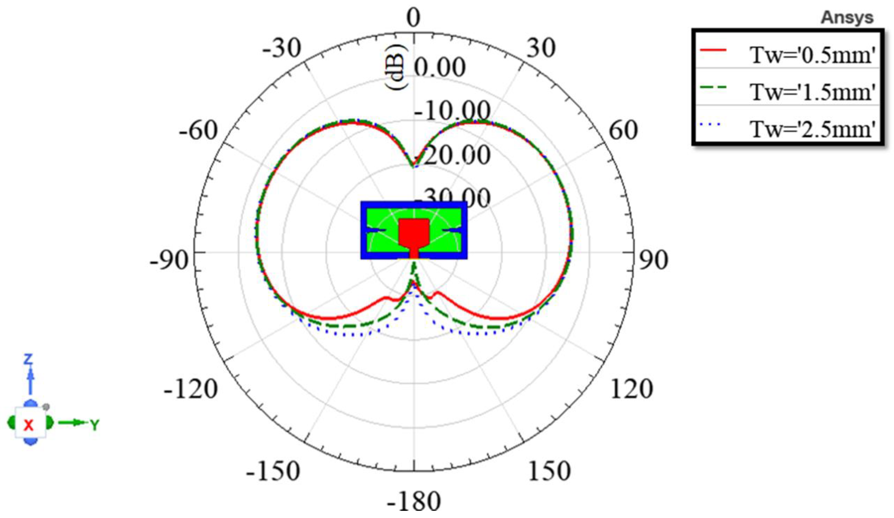
From (2) and (5), the normalized total field at 5.8 GHz changes as changes, and from (3), gets closer to as decreases closer to zero. Hence, the end-fire radiation becomes more significant as decreases. Figure 10 shows the simulated vertically polarized radiation patterns at 5.8 GHz in the y–z plane for different values of . The simulated data are in agreement with (2), (3), and (5), and the end-fire radiation becomes more significant as decreases.
4. The Comparisons of Simulated Data and Measured Results of The Prototype
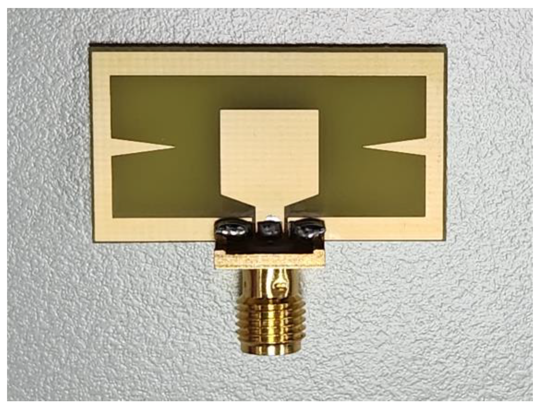
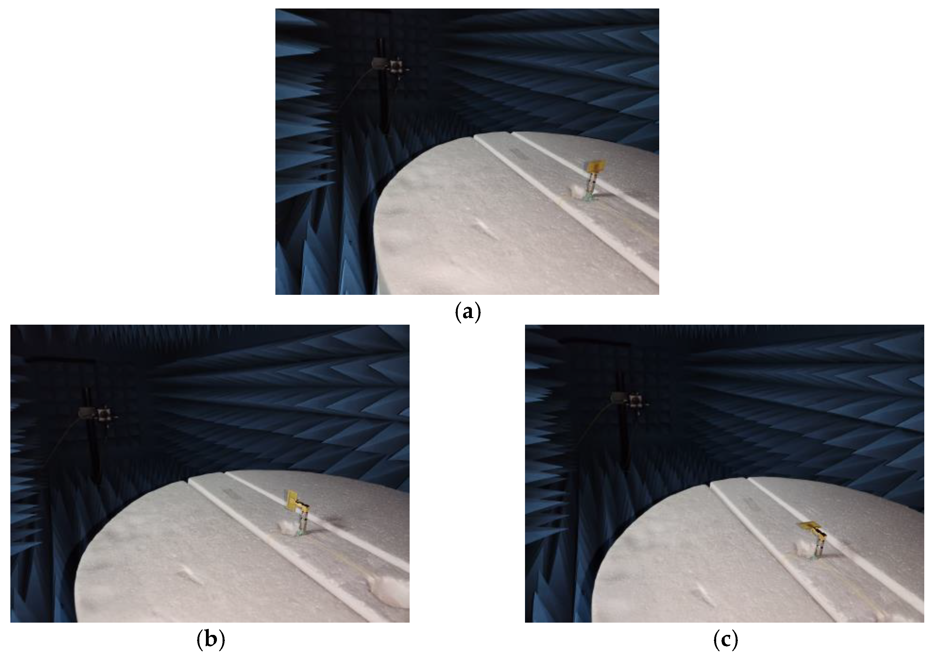
Figure 11 shows the prototype of the proposed antenna with an SMA connector [20] soldered to it, where the hand-soldered tin was not incorporated into the simulation. The antenna was measured by the Atenlab A3 compact-type OTA measurement system [21] and compared with its simulated data. Figure 12a–c show the measurement setup for radiation patterns in the x–y, x–z, and y–z planes. The proposed antenna was placed on a turntable and connected to the coaxial cable of the measurement system, which was not incorporated into the simulation. Figure 12a shows that the proposed antenna was connected directly to the coaxial cable of the measurement system, and the cable was parallel to the z-axis of the proposed antenna. Figure 12b,c show that the proposed antennas were connected to the coaxial cable of the measurement system via a right-angle SMA adapter [22], and the cable was perpendicular to the z-axis of the proposed antennas.
4.1. Reflection Coefficients
Figure 13 compares the simulated and measured reflection coefficients of the proposed antenna. The simulated curve shows that the proposed antenna can meet from 2.11 to 2.58 GHz and 5.06 to 7.5 GHz, where the fractional bandwidths are 20.04% and 38.05%, respectively. The measured result agrees with the simulated one and can meet Wi-Fi 2.4 and 5.8 GHz requirements for small UAV applications.
4.2. Radiation Patterns
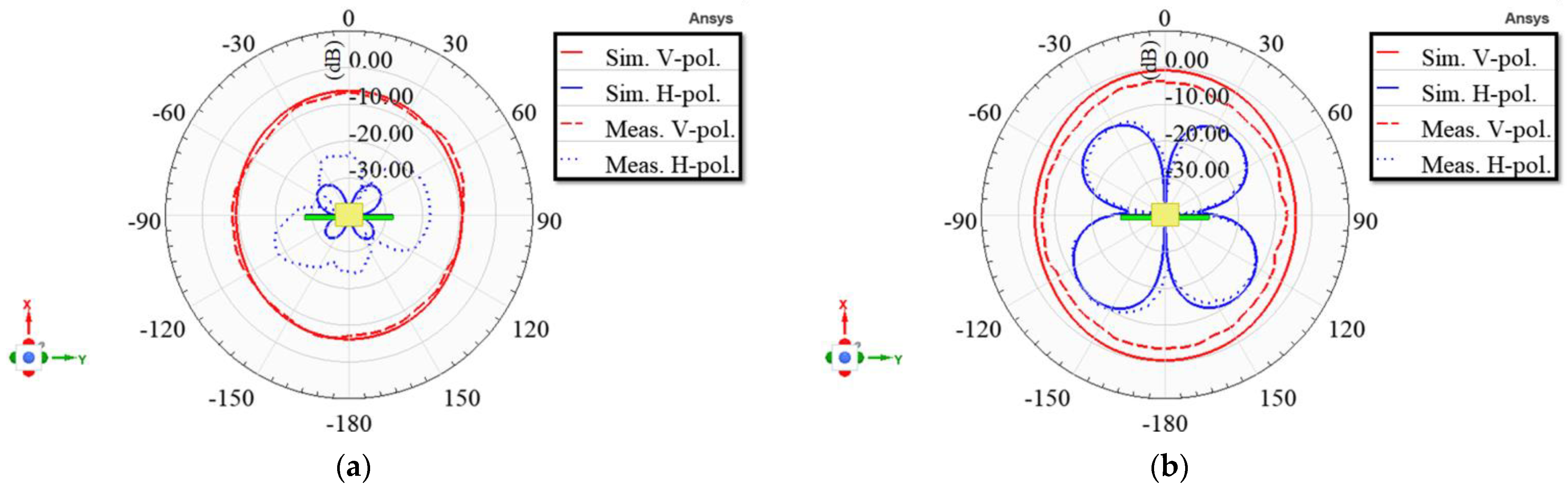
Figure 14, Figure 15 and Figure 16 show the comparisons of the simulated and measured radiation patterns of the proposed antenna in the x–y, x–z, and y–z planes. The simulated data show that the proposed antenna has good vertically polarized radiation. Figure 14a,b show the radiation patterns of the proposed antenna in the x–y plane at 2.4 and 5.8 GHz, respectively, and the vertically polarized radiations are quasi-omnidirectional. Due to the hand-soldered tins on the main radiation areas of 2.4 GHz, the measured horizontally polarized radiation is larger than the simulated one, as shown in Figure 14a.
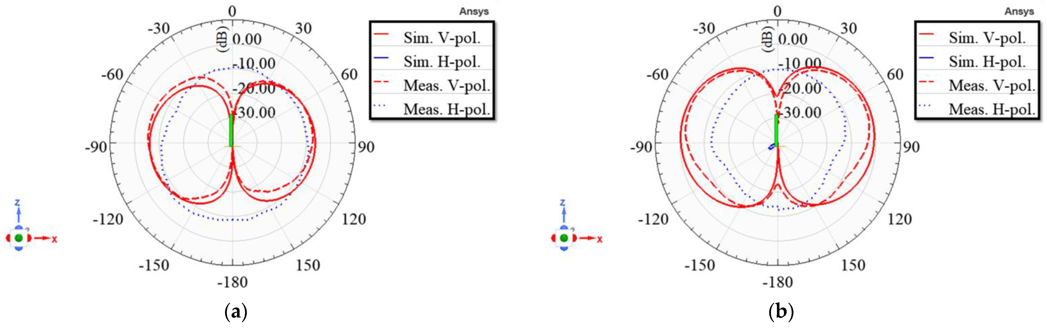
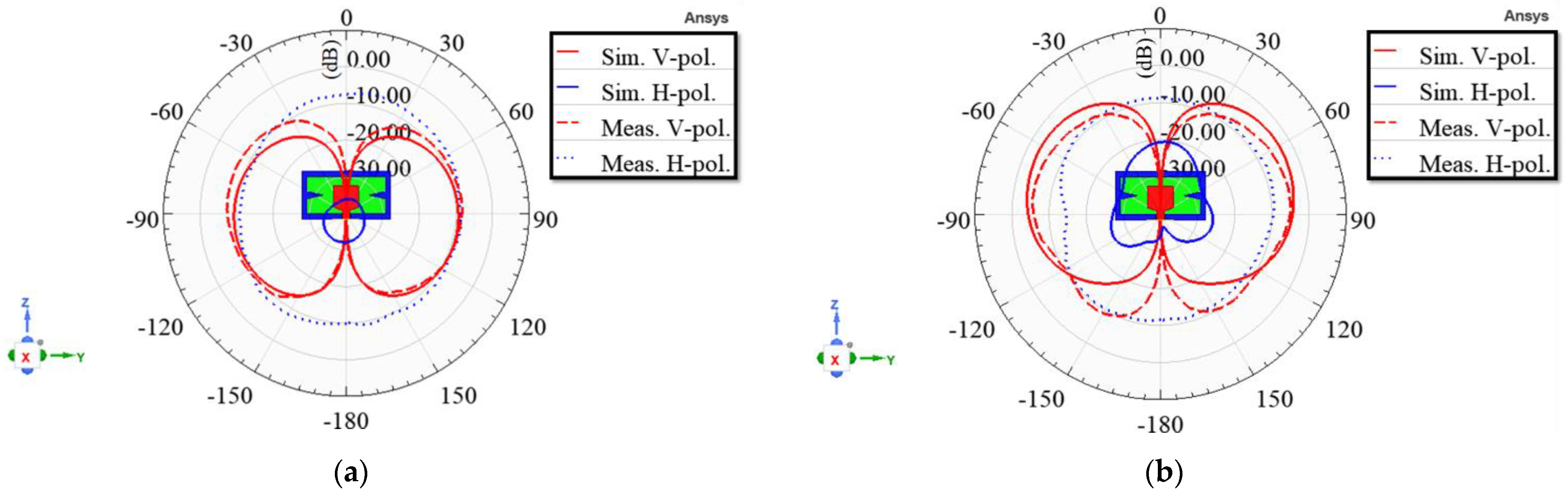
In the x–z and y–z planes, due to the cable effect, the measured horizontally polarized radiations are much larger than the simulated data, as shown in Figure 15 and Figure 16. In addition, due to the cable effect, the measured vertically polarized radiation is larger than the simulated one at −120° to +120° in the y–z plane at 5.8 GHz, as shown in Figure 16b. The simulated vertically polarized radiation patterns at 2.4 GHz are quasi-omnidirectional, and the maximum radiations in the x–z and y–z planes are near the horizontal plane, as shown in Figure 14a, Figure 15a and Figure 16a. The simulated vertically polarized radiation patterns at 5.8 GHz have stronger radiation in the upper hemisphere (below the UAV), as shown in Figure 15b and Figure 16b. Its maximum radiations in the x–z and y–z planes are in the upper hemisphere and between 14 and 29° from the horizontal plane.
Table 2 displays the characteristics of the simulated vertically polarized radiation patterns. Ignoring the influence caused by the hand-soldered tin and the measurement system’s cable effect, all measured radiation pattern results agree with simulated data. In E-planes, the beamwidths of relative −10 dB at 2.4 GHz are no less than 142°. Moreover, at 5.8 GHz, maximum gain angles are between 17 and 29° off the horizontal.
Table 3 compares the proposed antenna and published works on planar antennas. The proposed planar antenna has the following advantages. First, it has a single-sided structure, which has a relatively low cost to make small UAVs more affordable. Second, it has a minimum electrical length (L) of 0.132 and a low profile (h) of 0.0128 to meet the portability and aerodynamic requirements for small UAV applications. Third, at 5.8 GHz, it has stronger radiation in the upper hemisphere (below the small UAV) to reduce interference from rare-use directions. Its maximum radiations are below the UAV and between 14 and 29° from the horizontal plane to provide more antenna gain when the small UAV flies farther in urban areas. At 2.4 GHz, it has quasi-omnidirectional radiation to ensure a stable link in all directions. Its maximum radiations are near the horizontal plane to provide more antenna gain when the small UAV flies farther in open areas. Finally, it has good vertically polarized radiation at 2.4 and 5.8 GHz for long-distance applications.
5. Conclusions
In summary, we proposed a compact planar Wi-Fi antenna with optimized radiation patterns for small UAV applications in urban and open areas. The proposed antenna was prototyped and measured, and the measured results agree with the simulated data. It has end-fire radiation to reduce the interference from rare-use directions at 5.8 GHz and quasi-omnidirectional radiation to ensure a stable link in all directions at 2.4 GHz. The directions of the maximum radiation in each elevation plane at 5.8 and 2.4 GHz provide more antenna gain when the small UAV flies farther in urban and open areas. In future work, the proposed antenna will be mounted on a small UAV for field experiments.
Author Contributions
Conceptualization, Y.-L.Y. and D.-B.L.; methodology, Y.-L.Y. and D.-B.L.; software, Y.-L.Y.; validation, Y.-L.Y. and D.-B.L.; formal analysis, Y.-L.Y. and D.-B.L.; investigation, Y.-L.Y. and D.-B.L.; resources, D.-B.L.; data curation, Y.-L.Y. and D.-B.L.; writing—original draft, Y.-L.Y.; writing—review and editing, D.-B.L.; visualization, Y.-L.Y.; supervision, D.-B.L.; project administration, D.-B.L. All authors have read and agreed to the published version of the manuscript.
Funding
This work was supported by the Ministry of Science and Technology of Taiwan under Grant MOST 110-2221-E-011-052.
Institutional Review Board Statement
Not applicable.
Informed Consent Statement
Not applicable.
Data Availability Statement
All the design parameters and related data are provided in this article.
Conflicts of Interest
The authors declare no conflict of interest.
References
- Xu, C.; Liao, X.; Tan, J.; Ye, H.; Lu, H. Recent Research Progress of Unmanned Aerial Vehicle Regulation Policies and Technologies in Urban Low Altitude. IEEE Access 2020, 8, 74175–74194. [Google Scholar] [CrossRef]
- Balanis, C.A. Antenna Theory: Analysis and Design, 4th ed.; Wiley: New York, NY, USA, 2016; Chapter 2; p. 89. [Google Scholar]
- Barani, N.; Harvey, J.F.; Sarabandi, K. Fragmented Antenna Realization Using Coupled Small Radiating Elements. IEEE Trans. Antennas Propag. 2018, 66, 1725–1735. [Google Scholar] [CrossRef]
- Pfeiffer, C.; Dagefu, F.T. A Compact Electrically Tunable VHF Antenna. In Proceedings of the 2019 IEEE International Symposium on Antennas and Propagation and USNC-URSI Radio Science Meeting, Atlanta, GA, USA, 7–12 July 2019; pp. 1549–1550. [Google Scholar] [CrossRef]
- Sun, L.; Sun, B.; Yuan, J.; Tang, W.; Wu, H. Low-Profile, Quasi-Omnidirectional Substrate Integrated Waveguide (SIW) Multihorn Antenna. IEEE Antennas Wirel. Propag. Lett. 2016, 15, 818–821. [Google Scholar] [CrossRef]
- Pradhan, S.; Gupta, B. High-Gain Dual-Mode Cylindrical Rectangular Patch Antenna for Airborne Applications. IEEE Trans. Aerosp. Electron. Syst. 2022, 58, 4168–4179. [Google Scholar] [CrossRef]
- Duran-Pardo, A.V.; Navarro-Mendez, D.V.; Carrera-Suarez, L.F.; Baquero-Escudero, M. Conformal Patch Antennas for an UAV employed in Agricultural Applications. In Proceedings of the 2020 IEEE International Symposium on Antennas and Propagation and North American Radio Science Meeting, Montreal, QC, Canada, 5–10 July 2020; pp. 285–286. [Google Scholar] [CrossRef]
- Han, Y.; Hu, K.; Zhao, R.; Gao, Y.; Dai, L.; Fu, Y.; Zhou, B.; Yuan, S. Design of Combined Printed Helical Spiral Antenna and Helical Inverted-F Antenna for Unmanned Aerial Vehicle Application. IEEE Access 2020, 8, 54115–54124. [Google Scholar] [CrossRef]
- Wang, C.; Yuan, B.; Shi, W.; Mao, J. Low-Profile Broadband Plasma Antenna for Naval Communications in VHF and UHF Bands. IEEE Trans. Antennas Propag. 2020, 68, 4271–4282. [Google Scholar] [CrossRef]
- Nosrati, M.; Jafargholi, A.; Pazoki, R.; Tavassolian, N. Broadband Slotted Blade Dipole Antenna for Airborne UAV Applications. IEEE Trans. Antennas Propag. 2018, 66, 3857–3864. [Google Scholar] [CrossRef]
- Chou, H.-T.; Lin, D.-B.; Chiu, H.-L. Planar Dual-Mode Dipole Antenna Formed by Artificial Microstrip Arms Loaded with Multiple H-Slots for Broadband Operation of Vertically Polarized Radiation on UAV Platform. IEEE Trans. Antennas Propag. 2022, 70, 7869–7877. [Google Scholar] [CrossRef]
- Yan, Y.-D.; Jiao, Y.-C. Omnidirection Vertically Polarized Antenna on Unmanned Aerial Vehicle. In Proceedings of the 2018 12th International Symposium on Antennas, Propagation and EM Theory (ISAPE), Hangzhou, China, 3–6 December 2018; pp. 1–3. [Google Scholar] [CrossRef]
- Sumi, M.; Suzuki, Y. A Wideband Single-Sided Folded-Off-Center-Fed Dipole Antenna for 4G/5G/Wi-Fi M2M/IoT Applications and UAVs. In Proceedings of the 2021 IEEE Conference on Antenna Measurements & Applications (CAMA), Antibes Juan-les-Pins, France, 15–17 November 2021; pp. 3–4. [Google Scholar] [CrossRef]
- Lin, D.-B.; Tang, I.-T.; Wei, Y.-J.; Lin, H.-P. A compact slot antenna with CPW-fed for IEEE 802.16-2004 applications. In Proceedings of the 2007 IEEE Antennas and Propagation Society International Symposium, Honolulu, HI, USA, 9–15 June 2007; pp. 4753–4756. [Google Scholar] [CrossRef]
- Reddy Maddikunta, P.K.; Hakak, S.; Alazab, M.; Bhattacharya, S.; Gadekallu, T.R.; Khan, W.Z.; Pham, Q.-V. Unmanned Aerial Vehicles in Smart Agriculture: Applications, Requirements, and Challenges. IEEE Sens. J. 2021, 21, 17608–17619. [Google Scholar] [CrossRef]
- IEEE Std 145-2013 (Revision of IEEE Std 145-1993); IEEE Standard for Definitions of Terms for Antennas. IEEE: New York, NY, USA, 2014; pp. 1–50. [CrossRef]
- David, K.C. Fundamentals of Engineering Electromagnetics; Addison-Wesley: Menlo Park, CA, USA, 1993; Chapter 10; pp. 432–433. [Google Scholar]
- Balanis, C.A. Antenna Theory: Analysis and Design, 4th ed.; Wiley: New York, NY, USA, 2016; Chapter 6; p. 287. [Google Scholar]
- ANSYS Incorporation, High-Frequency Structure Simulator (HFSS), Version 2022 R1, 7 November 2022. Available online: https://www.ansys.com/products/electronics/ansys-hfss (accessed on 16 June 2023).
- SMA PCB End Launch Straight Jack 50 Ohm, Amphenol Corporation. January 2023. Available online: https://www.amphenolrf.com/901-10309.html (accessed on 16 June 2023).
- Atenlab A3 Measurement System, PCB GraphTech Pte. November 2022. Available online: https://pcbgt.com.sg/atenlab-a3 (accessed on 16 June 2023).
- SMA Jack to SMA Plug Adapter 50 Ohm Right Angle, Amphenol Corporation. January 2023. Available online: https://www.amphenolrf.com/132172.html (accessed on 16 June 2023).
Figure 1.
Common scenarios of light-and-small civil UAV applications in urban areas.

Figure 2.
The structure of the proposed antenna with geometrical parameters.

Figure 3.
The main design steps of the proposed antenna.

Figure 4.
The simulated surface current density at 5.8 GHz.

Figure 5.
Far-field observation of a two-element array consisting of two point sources, Elements 1 and 2, positioned along the z-axis.
Figure 5.
Far-field observation of a two-element array consisting of two point sources, Elements 1 and 2, positioned along the z-axis.

Figure 6.
The relative power patterns of the vertical infinitesimal dipole, the array factor of Elements 1 and 2, and the total field of the two-element array antenna.
Figure 6.
The relative power patterns of the vertical infinitesimal dipole, the array factor of Elements 1 and 2, and the total field of the two-element array antenna.

Figure 7.
The simulated surface current density at 2.4 GHz.

Figure 8.
The simulated reflection coefficients for different values of .

Figure 9.
The simulated reflection coefficients for different values of .

Figure 10.
The simulated vertically polarized radiation patterns at 5.8 GHz in the y–z plane for different values of .
Figure 10.
The simulated vertically polarized radiation patterns at 5.8 GHz in the y–z plane for different values of .

Figure 11.
The prototype of the proposed antenna with an SMA connector soldered to it.

Figure 12.
The measurement setup for radiation patterns. (a) x–y plane; (b) x–y plane; (c) x–y plane.
Figure 12.
The measurement setup for radiation patterns. (a) x–y plane; (b) x–y plane; (c) x–y plane.

Figure 13.
The comparison of the simulated and measured reflection coefficients of the proposed antenna.
Figure 13.
The comparison of the simulated and measured reflection coefficients of the proposed antenna.

Figure 14.
Comparison of the proposed antenna’s simulated and measured radiation patterns in the x–y plane. (a) 2.4 GHz; (b) 5.8 GHz.
Figure 14.
Comparison of the proposed antenna’s simulated and measured radiation patterns in the x–y plane. (a) 2.4 GHz; (b) 5.8 GHz.

Figure 15.
Comparison of the proposed antenna’s simulated and measured radiation patterns in the x–z plane. (a) 2.4 GHz; (b) 5.8 GHz.
Figure 15.
Comparison of the proposed antenna’s simulated and measured radiation patterns in the x–z plane. (a) 2.4 GHz; (b) 5.8 GHz.

Figure 16.
Comparison of the proposed antenna’s simulated and measured radiation patterns in the y–z plane. (a) 2.4 GHz; (b) 5.8 GHz.
Figure 16.
Comparison of the proposed antenna’s simulated and measured radiation patterns in the y–z plane. (a) 2.4 GHz; (b) 5.8 GHz.


Table 1.
The values of geometrical parameters for the proposed antenna.
| Parameter | Dimension (mm) | Ratio to the Wavelength of 2.4 GHz in Vacuum | Ratio to the Wavelength of 5.8 GHz in Vacuum | Angle (Degree) |
|---|---|---|---|---|
| W | 30.3 | 0.24 | 0.59 | N/A |
| 27.3 | 0.22 | 0.53 | N/A | |
| L | 16.5 | 0.13 | 0.32 | N/A |
| 12.5 | 0.10 | 0.24 | N/A | |
| 12.1 | 0.10 | 0.23 | N/A | |
| 1.5 | 0.01 | 0.03 | N/A | |
| 2 | 0.02 | 0.04 | N/A | |
| 5.75 | 0.05 | 0.11 | N/A | |
| 5.5 | 0.04 | 0.11 | N/A | |
| a | 8.5 | 0.07 | 0.16 | N/A |
| b | 8.5 | 0.07 | 0.16 | N/A |
| c | 1 | 0.01 | 0.02 | N/A |
| 5.7 | 0.05 | 0.11 | N/A | |
| 1.5 | 0.01 | 0.03 | N/A | |
| 2.5 | 0.02 | 0.05 | N/A | |
| g | 0.3 | 0.00 | 0.01 | N/A |
| 0.035 | 0.00 | 0.00 | N/A | |
| h | 1.6 | 0.01 | 0.03 | N/A |
| Beta | N/A | N/A | N/A | 20 |
Table 2.
Characteristics of the simulated vertically polarized radiation patterns.
| Unit: Degree | Y–z Plane | x–z Plane | ||||||||
|---|---|---|---|---|---|---|---|---|---|---|
| Left Plane | Right Plane | Left Plane | Right Plane | |||||||
| 2.4 GHz | Maximum gain angle | −98 | 98 | −95 | 91 | |||||
| Relative −3 dB | Beam angle | −142 | −49 | 48 | 142 | −139 | −49 | 46 | 134 | |
| Beamwidth | 93 | 94 | 90 | 88 | ||||||
| Relative −10 dB | Beam angle | −165 | −20 | 19 | 165 | −165 | −21 | 18 | 160 | |
| Beamwidth | 145 | 146 | 144 | 142 | ||||||
| 5.8 GHz | Maximum gain angle | −61 | 62 | −76 | 73 | |||||
| Relative −3 dB | Beam angle | −102 | −29 | 29 | 103 | −118 | −39 | 37 | 114 | |
| Beamwidth | 72.96 | 74 | 79 | 77 | ||||||
| Relative −10 dB | Beam angle | −127 | −11 | 11 | 129 | −152 | −16 | 14 | 148 | |
| Beamwidth | 116 | 118 | 136 | 134 | ||||||
Table 3.
The comparison of the proposed antenna and published works on planar antennas.
| Ref. | Structure | Operating Frequency | Radiation Pattern | Electrical Dimensions | |
|---|---|---|---|---|---|
| for Urban Areas | for Open Areas | ||||
| [11] | Double-sided | 0.86 to 1.51 | Yes | ||
| [12] | Double-sided | 3.9 to 5 | Yes | ||
| [13] | Single-sided | 3.5/3.7/4.5/5/5.7 | Yes | Yes | |
| [14] | Single-sided | 2.4 to 5.8 | Yes | ||
| This work | Single-sided | 2.4/5.8 | Yes | Yes | |
Disclaimer/Publisher’s Note: The statements, opinions and data contained in all publications are solely those of the individual author(s) and contributor(s) and not of MDPI and/or the editor(s). MDPI and/or the editor(s) disclaim responsibility for any injury to people or property resulting from any ideas, methods, instructions or products referred to in the content. |
© 2023 by the authors. Licensee MDPI, Basel, Switzerland. This article is an open access article distributed under the terms and conditions of the Creative Commons Attribution (CC BY) license (https://creativecommons.org/licenses/by/4.0/).
Share and Cite
MDPI and ACS Style
Yang, Y.-L.; Lin, D.-B. A Compact Planar Wi-Fi Antenna with Optimized Radiation Patterns for Small UAV Applications. Appl. Sci. 2023, 13, 7470. https://0-doi-org.brum.beds.ac.uk/10.3390/app13137470
AMA Style
Yang Y-L, Lin D-B. A Compact Planar Wi-Fi Antenna with Optimized Radiation Patterns for Small UAV Applications. Applied Sciences. 2023; 13(13):7470. https://0-doi-org.brum.beds.ac.uk/10.3390/app13137470
Chicago/Turabian StyleYang, Ya-Lung, and Ding-Bing Lin. 2023. "A Compact Planar Wi-Fi Antenna with Optimized Radiation Patterns for Small UAV Applications" Applied Sciences 13, no. 13: 7470. https://0-doi-org.brum.beds.ac.uk/10.3390/app13137470
Note that from the first issue of 2016, this journal uses article numbers instead of page numbers. See further details here.