
Enhanced Heat Transfer Study of Spherical Heat Storage Based on Response Surface Methodology
1
College of Energy and Power Engineering, Inner Mongolia University of Technology, Hohhot 010051, China
2
Inner Mongolia Key Laboratory of Renewable Energy, Hohhot 010051, China
3
College of Electrical Engineering, Inner Mongolia University of Technology, Hohhot 010051, China
4
College of Energy and Transportation Engineering, Inner Mongolia Agricultural University, Hohhot 010018, China
*
Author to whom correspondence should be addressed.
Appl. Sci. 2023, 13(15), 8595; https://0-doi-org.brum.beds.ac.uk/10.3390/app13158595
Submission received: 25 June 2023
/
Revised: 20 July 2023
/
Accepted: 20 July 2023
/
Published: 26 July 2023
(This article belongs to the Special Issue Flow and Heat Transfer Research in Multiphase Flow and Porous Media)
Abstract
:In this paper, the effect of melting characteristics of CuO/paraffin wax composite phase change material in a spherical heat storage unit in a constant temperature water bath is investigated. Experiments were conducted in three different water bath temperatures (65 °C, 70 °C, and 75 °C). The inner surface of the sphere was fixed with two, four, and six pin-shaped fins 3 mm in diameter. The spheres were filled with different mass fractions of CuO nanoparticles/paraffin phase change materials. Experimental CCD was used to model and optimize the spherical thermal storage unit. Regression models were developed to predict the effects of various operational factors on the melting time of the composite PCM. The factors in the model included the number of pin fins in the spherical heat storage unit, the water bath temperature, and the content of added CuO nanoparticles in the PCM, and ANOVA was used to statistically validate the regression model. The results showed that the interaction between the water bath temperature and the number of pin fins had the most significant effect on the melting time. With the melting time of the phase change material as the optimized objective function, the optimized optimal working condition was six pin fins, a water bath temperature of 75 °C, and the addition of 5 wt% CuO nanoparticles/paraffin phase change material, and the actual melting time under this condition was 78.9 min, which was lower than the predicted value of 79.4 min, with an error of 0.63% between them.
1. Introduction
In recent years, phase change thermal storage technology has been used in areas such as waste heat recovery and solar energy storage to cover the differences in quantity, form, and space between energy supply and demand. Phase change thermal storage materials are widely used in latent heat storage because of their high heat storage density, almost constant temperature during the heat storage/exothermic process, wide melting point distribution, chemical stability, and corrosion resistance [1]. Paraffin waxes are stable as phase change materials, free from subcooling and phase separation, cheap, and non-toxic, but they also have drawbacks, such as low thermal conductivity. With the rapid development of nanotechnology, the addition of nanoparticles (e.g., CuO [2,3], Al2O3 [4,5], Fe3O4 [6,7], SiO2 [8,9], etc.) with high thermal conductivity to paraffin wax has become an emerging means [10]. Chen [11] prepared CuO/paraffin nanopowder composite phase change materials with mass fractions of 0.01–0.1%. The results showed that the addition of CuO nanopowder to paraffin wax could greatly improve the solar thermal conversion capacity by enhancing the light absorption capacity of the PCM. At low mass concentrations (0–0.1%), the steady-state temperature gradually increased with increasing mass fraction of CuO nanoparticles, with a maximum increase of about 2.3 times. A nanocomposite for energy storage was prepared by Lin [12] by adding 20 nm nanoparticles of Cu to paraffin wax. The addition of 2.0% Cu nanoparticles to paraffin wax was found to increase the thermal conductivity of the Cu/paraffin phase change material by 46.3%. Kumar [13] dispersed ZnO nanoparticles in paraffin and analyzed their thermal properties. The experimental results showed that ZnO nanoparticles distributed inside the paraffin wax without affecting its chemical structure greatly improved its thermal stability and increased its thermal conductivity to 41.67% at 2.0 wt%. Pasupathi [14] experimentally investigated the effect of hybrid nanoparticles containing SiO2 and CeO2 nanoparticles on the thermophysical properties of paraffin-based phase change materials (PCMs). The experimental results showed that the mixed nanoparticles spread uniformly in the paraffin matrix without affecting the chemical arrangement of paraffin molecules. When hybrid nanoparticles were dispersed in paraffin, the relative thermal stability and relative thermal conductivity of paraffin were increased synergically, reaching 115.49% and 165.56%, respectively. In addition, the hybrid nanoparticles appropriately changed the melting point and crystallization point of the paraffin wax and reduced the degree of supercooling of the paraffin wax; the maximum degree of supercooling was reduced by 35.81%. Li [15] conducted an experimental study of the melting and solidification processes and the enhancement of thermal conductivity of PCM inside a sphere. The enhancement of the thermal conductivity of PCM by aluminum powder was investigated via homogeneous diffusion and sedimentation methods. The results showed that the addition of aluminum powder accelerated the melting and solidification processes of PCM within the sphere. However, the settling of the aluminum powder during the melting process was more conducive to accelerated heat transfer throughout the sphere than the uniform diffusion of the aluminum powder in the PCM.
As the main component of a phase change heat storage system, the phase change unit is a key part of the heat transfer efficiency of the system, and the heat transfer performance is closely related to its shape and structure. Common geometries for phase change heat storage units include square, cylindrical, spherical, and toroidal. The spherical shape has the largest heat transfer area for the same volume of heat storage unit. Ismail [16] visualized the solid–liquid interface inside a spherical capsule through experiments and numerical simulations. Asker [17] performed a numerical analysis of the inward solidification of PCM in spherical capsules. The results show that large-diameter spherical capsules have longer solidification times than small-diameter capsules. The entropy generation increases with increasing spherical capsule diameter and decreases after reaching a maximum.
The enhancement of heat transfer by adding fins to the heat storage unit has been investigated [18]. Li [19] installed fins on PCM shells in horizontal and vertical directions. The results showed that the triple fins in the vertical direction and double fins in the horizontal direction had the best melting enhancement for PCM with the best fire use efficiency. Koizumi [20] inserted copper plates inside spherical capsules to improve the latent heat storage rate of solid PCM and found that the latent heat storage rate was significantly increased. Bouguila [21] proposed a novel heat sink model consisting of nano-enhanced phase change materials and pin fins for the thermal management of electronic devices. The effects of fin thickness and fin number on the performance of PCM fins were investigated. The results showed that the increase in fin volume fraction and nanoparticle concentration did not improve the performance of the heat sink. Because of the high thermal conductivity of the fin, the dispersion of nanoparticles in the fin radiator had no significant effect on the thermal response. Fan [22] investigated the heat transfer process of PCM-confined melting in spherical capsules through experiments and numerical simulations and found a 30% reduction in melting time when the largest fin height was used. Aziz [23] used Ansys CFX to simulate the heat storage and release of PCM encapsulated in spheres, using pins and copper plating to improve the heat transfer of PCM within the spheres. The results showed that copper-plated spheres with pins had a 37% reduction in phase transition time compared to normal PCM spheres. Premnath [24] experimentally investigated frozen water in stainless-steel spherical containers with inner fins of different lengths. The results show that in a spherical vessel with a diameter of 75 mm, it is recommended to install four 13.5 mm–long heat sinks to achieve maximum heat flux.v. The highly conductive fins helped accelerate the phase change and obtain the best energy-saving effect. Meghari [25] investigated the melting process of PCM inside a spherical capsule using numerical simulation. The melting processes of regular fins and hollow fins at different angles were compared. The results showed that the fins and their geometry play a key role in the melting process. Changing the inclination angle of the fins does not always enhance the heat transfer. However, adding hollow fins is more effective than regular fins. Sharma [26] investigated the effect of fin position within a spherical capsule on melting time, with an enhancement of 107.28% when the fins were centrally located. Lou [27] studied the strengthening effects of metal foams and fins on ice storage spheres through numerical simulations. The temperature field, ice front evolution, solidification fraction, total solidification time, and cold storage capacity under four different strengthening modes (plane, fins, metal foam, and metal foam composite fins) were analyzed, and the optimal porosity was obtained. Amin [28] studied the enhanced heat transfer of a single PCM sphere in TES systems. The results showed that adding pins to the sphere reduced the charging time by 34%. Sun [29] proposed a new double-layer spherical phase change heat storage structural unit and investigated the effect of fins on its melting behavior by numerical simulation to elucidate the mechanism of enhanced heat transfer coupling between dual local natural convection and heat conduction in the spherical heat storage unit. Combining factors such as complete melting time and entropy production, the optimal installation position of the fins was determined as the outer side of the inner sphere. The optimal combination of double-layer spherical fins was obtained through single-factor analysis of the number, height, and thickness of double-layer spherical fins. For a spherical capsule with an outer diameter of 50 mm and an inner diameter of 30 mm, the optimal combination of fin parameters was Num = 3, H/L = 80%, and D = 0.5 mm.
Based on the above studies, it can be seen that there are various methods to enhance thermal storage technology. There are studies conducted for phase change materials, and there are also studies on the strengthening of thermal storage structures. However, mostly only one of the enhanced methods has been analyzed, with a lack of research on the combination of multiple factors. Doss [30] investigated the effect of fin length, bath temperature, and frozen mass on solidification time using the RSM. The results of the study are instructive for this paper. This study focuses on the addition of pin fins inside a spherical heat storage unit filled with nanocomposite phase change materials and uses the response surface method to comprehensively analyze the effect of different means on the enhanced heat transfer effect.
The objectives of this study were to (a) investigate the effect of pin fins on the melting characteristics of PCM in spherical thermal storage units; (b) determine the parameters affecting the melting time of PCM; and (c) develop a regression model for the melting time of PCM and predict new data after experimental confirmation.
2. Experimental Procedure
2.1. Design of Experiments
Paraffin mainly comprises straight-chain compounds. The latent heat and temperature of the phase transition of paraffin change with the growth of the carbon chain and increase with the growth of the carbon chain under normal circumstances. As the carbon chain grows and the melting point increases, the growth rate starts out fast, but it becomes slower and slower as the chain increases. However, the thermal conductivity of paraffin wax is low. Obviously, this lower thermal conductivity results in a low heat storage/release rate. In order to solve the problems of the low thermal conductivity, uneven temperature distribution, and low heat storage/release rate of pure paraffin PCMs, this study used composite PCMs to improve the thermal performance of paraffin PCMs.
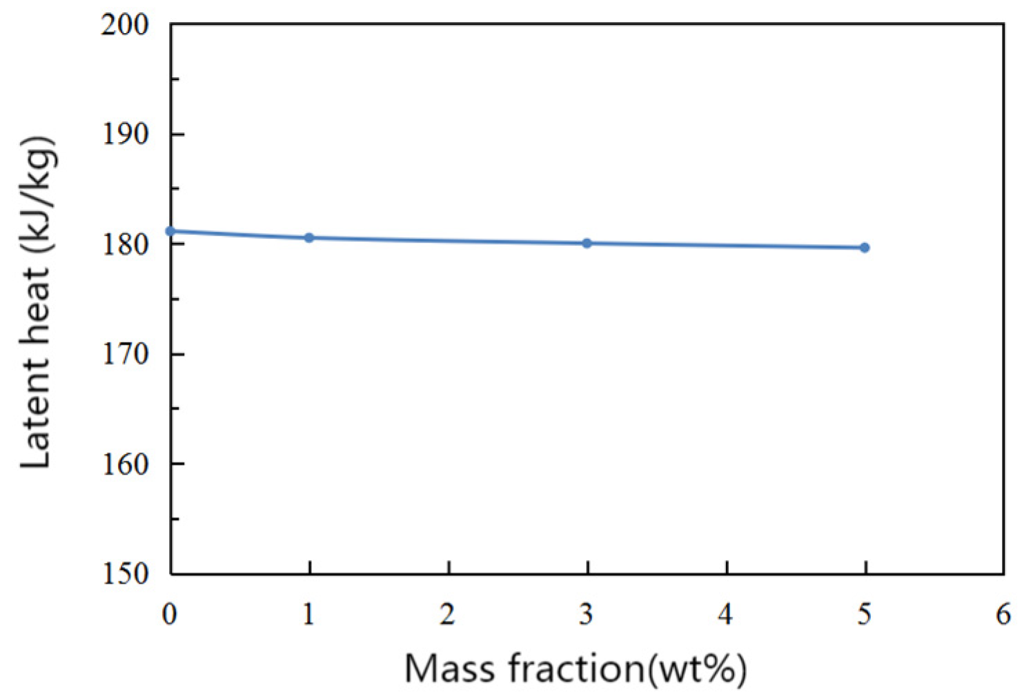
Paraffin wax was used as the phase change material. With the “two-step” method, a certain amount of paraffin wax was weighed into a beaker and then placed in a constant temperature water bath at 80 °C to melt the paraffin wax completely, while a certain amount of CuO nanoparticles were weighed and added to the melted paraffin wax. The CuO nanoparticles were added to the melted paraffin wax and stirred with a magnetic stirrer for 30 min to make them fully integrated and then treated with an ultrasonic shaker for 60 min to disperse the CuO nanoparticles evenly in the paraffin wax to prepare a CuO/paraffin wax composite phase change material. Figure 1 shows the variation curve of the latent heat of phase transition of CuO/paraffin wax composite phase change materials in the case of different mass fractions measured using DSC.
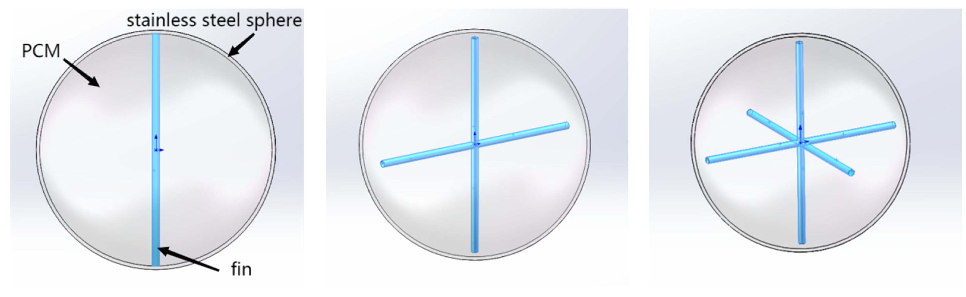
Two 304 stainless-steel hemispherical vessels were selected and flanged externally, and the two hemispheres were encapsulated into a complete spherical vessel using bolts, resulting in the spherical shell of the phase change heat storage unit used in this study. The inner diameter of the sphere was 97 mm, the thickness was 1.5 mm, and the sphere was welded with 3 mm–diameter pin fins made of aluminum alloy in quantities of 2, 4, and 6, as shown in Figure 2.
The composite phase change materials filled the heat storage sphere through small holes in the top of the sphere shell. The sphere shell was heated using an electric heating furnace to completely melt the composite phase change materials, which were added to the sphere in small quantities. Considering the thermal expansion of the phase change materials, the filling was terminated when the liquid phase change materials filled in the spheres reached a fixed height to ensure that no overflow would occur.
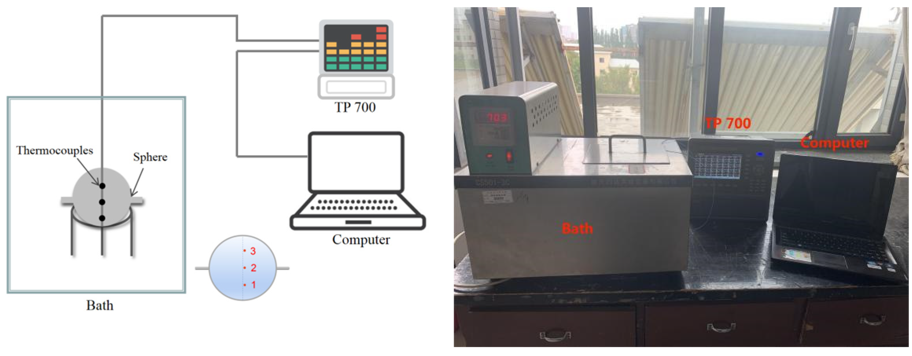
The experimental test system for melting within a spherical heat storage unit is shown in Figure 3. It mainly consisted of a constant temperature water bath, TP700 multi-channel data logger, thermocouples, and a heat storage sphere. K-type thermocouples were used for temperature testing and were arranged inside the sphere to record the internal temperature changes of the phase change materials during the melting process in real time. The locations of the thermocouples are shown in Figure 3. The duration the temperature at all monitoring points took to reach a steady-state value of 0.99 was taken as the melting time.
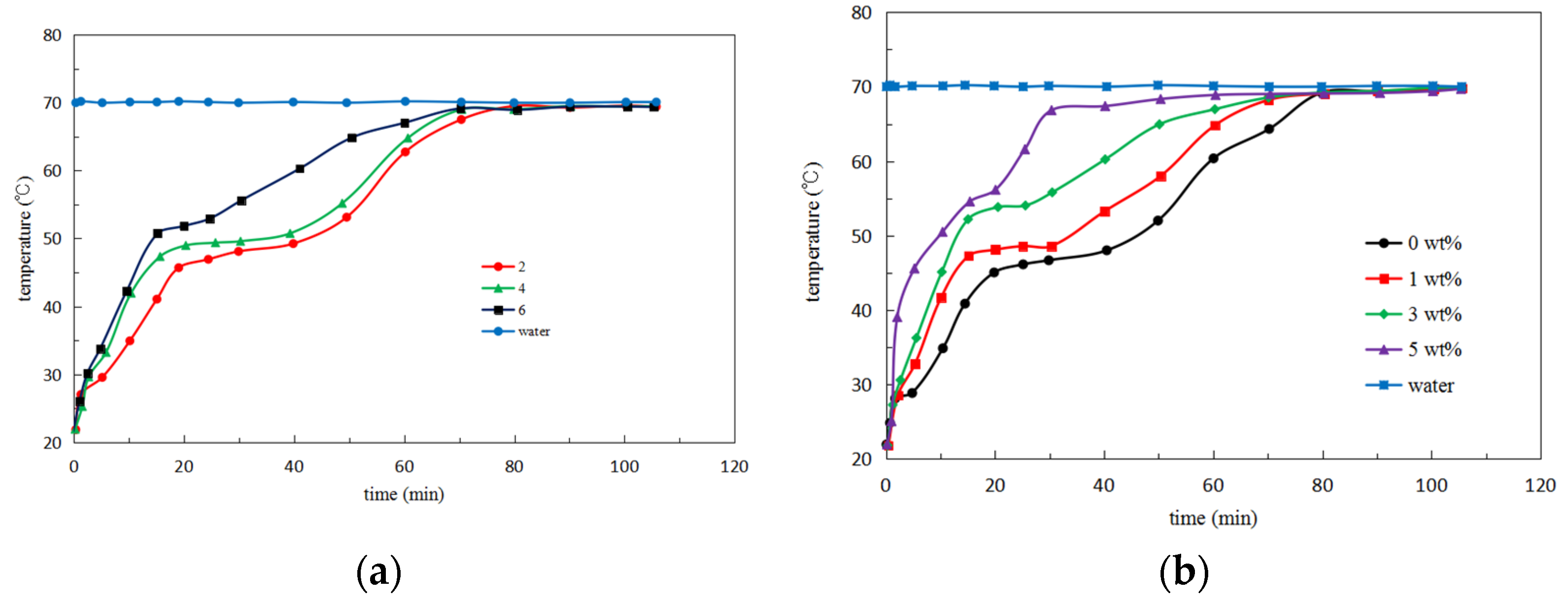
At a water bath temperature of 70 °C, the temperature variation of pure paraffin with three fin quantities is shown in Figure 4a. Figure 4b shows the temperature variation in the heat storage unit for different mass fractions of CuO. For all cases, at the beginning of melting, the heat in the water bath was transferred to the solid PCM, which absorbed heat and warmed up. When the temperature approached the phase change temperature, the solid PCM started to undergo phase change, and all the absorbed heat was used for latent heat. Thus, the temperature underwent a period of slower change. When the solid PCM phase change was completely transformed into liquid PCM, the absorbed heat made the liquid PCM temperature rise. At the same time, owing to the influence of natural convection, the hotter liquid PCM moved to the upper part of the sphere so that the temperature of measurement point 3 rapidly rose to the water bath temperature and tended to stabilize. As the number of fins/CuO mass fraction increased, the heat transfer to measurement point 3 was faster, and the final time to reach the water bath temperature was shorter.
2.2. Design of RSM
Response surface methodology (RSM) has been widely used in recent years for experimental design and optimization. RSM is an optimization method for experimental design that combines mathematics and statistics to enable correlation between the independent and dependent variables. The optimal working conditions are determined by analyzing the mathematical model established using RSM. Central composite design (CCD) is one of the most widely used experimental design methods in RSM that helps reduce the number of experiments used to achieve optimal conditions and analyze the interactions between parameters. In this study, CCD was applied to optimize the design of the complete melting time of phase change materials. The number of pin fins (N), water bath temperature (T), and the content of CuO in the nanocomposite phase change materials (M) were used as the factors for the study, and the effect of the three parameters on the complete melting time was analyzed using the response surface methodology. According to the central composite design principle, the values of three parameters were designed: 1 ≤ N ≤ 7, 62 °C ≤ T ≤ 78 °C, and 0 wt% ≤ M ≤ 6 wt%. The real values of each parameter were code-transformed to facilitate response surface analysis. After the coding conversion to determine the range of values, specific experimental conditions were designed, and the experiments were arranged on the melting test system according to the designed experimental conditions. The experimental data under each experimental condition were recorded. The coding levels of the influence factors of the operational parameters are shown in Table 1, and Table 2 shows the design scheme and results. For the measurement error of the measurement time, the experiment was conducted three times for each group under the same experimental conditions, and the melting time in Table 2 is the mean value of the three experiments. Table 3 shows the uncertainty analysis that existed during this experimentation
3. Results and Discussion
The experimental CCD included 20 groups. Groups 1–8 were orthogonal designs, and groups 9–14 formed a central composite design with α = ±1.68. Groups 15–20 were centroid designs used to estimate the experimental error. The experimental data obtained from Table 2 were analyzed using the second-order polynomial model obtained from Equation (1).
where y is the predicted response value; Xi and Xj are coded independent variables; β0, β1,..., βk, βij are regression coefficients; and ε is the statistical error. The least-squares method was used to determine the regression coefficients β. For each response, regression coefficients were obtained using coded variables, and then regression coefficients were calculated for the actual variables. Analysis of variance (ANOVA) was used to determine the valid parameters of the model and to interpret its significance.
After the regression fitting of each operational parameter, the regression model for the coding level of the complete melting time t is obtained as
The regression model for the actual level of complete melting time is
From Equation (2), it can be seen that the water bath temperature has a greater effect on the melting time because the absolute value coefficient of the water bath temperature is greater than the absolute value coefficient of the number of pin fins and the mass fraction of CuO nanoparticles. Although the three primary term coefficients are negative, the required melting time is as short as possible, so all three factors have a coordinating effect on the complete melting time. In the actual level of the quadratic regression mathematical model, comparing the magnitude of each interaction term coefficient, the order of interaction between interaction term factors can be derived from Equation (3), which shows that the order of interaction between interaction factors is M2 > T2 > N2 > NT > NM > TM.
Table 4 shows the ANOVA data for the complete melting time. The F-value was used to determine the statistical significance of the second-order regression model. When p < 0.05, the corresponding parameters were all significant, and when p < 0.0001 and F = 34.37 in the complete melting time model, the model was apparently significant. The coefficient of determination R2 is the ratio of the response contribution of the regression model, and the closer it is to one, the higher the model explanation. R2 = 0.9687. This indicates that more than 96.87% of the data deviations can be explained. The adequacy of the model can be tested by the correction decision coefficient R2adj, and R2adj = 0.9405, indicating a strong interaction between the predicted response values and the experimental results. AP is defined as a measure of the ratio of signal to noise, and AP > 4 is desirable. The model has AP = 22.2023, indicating that the regression equation is well-adapted.
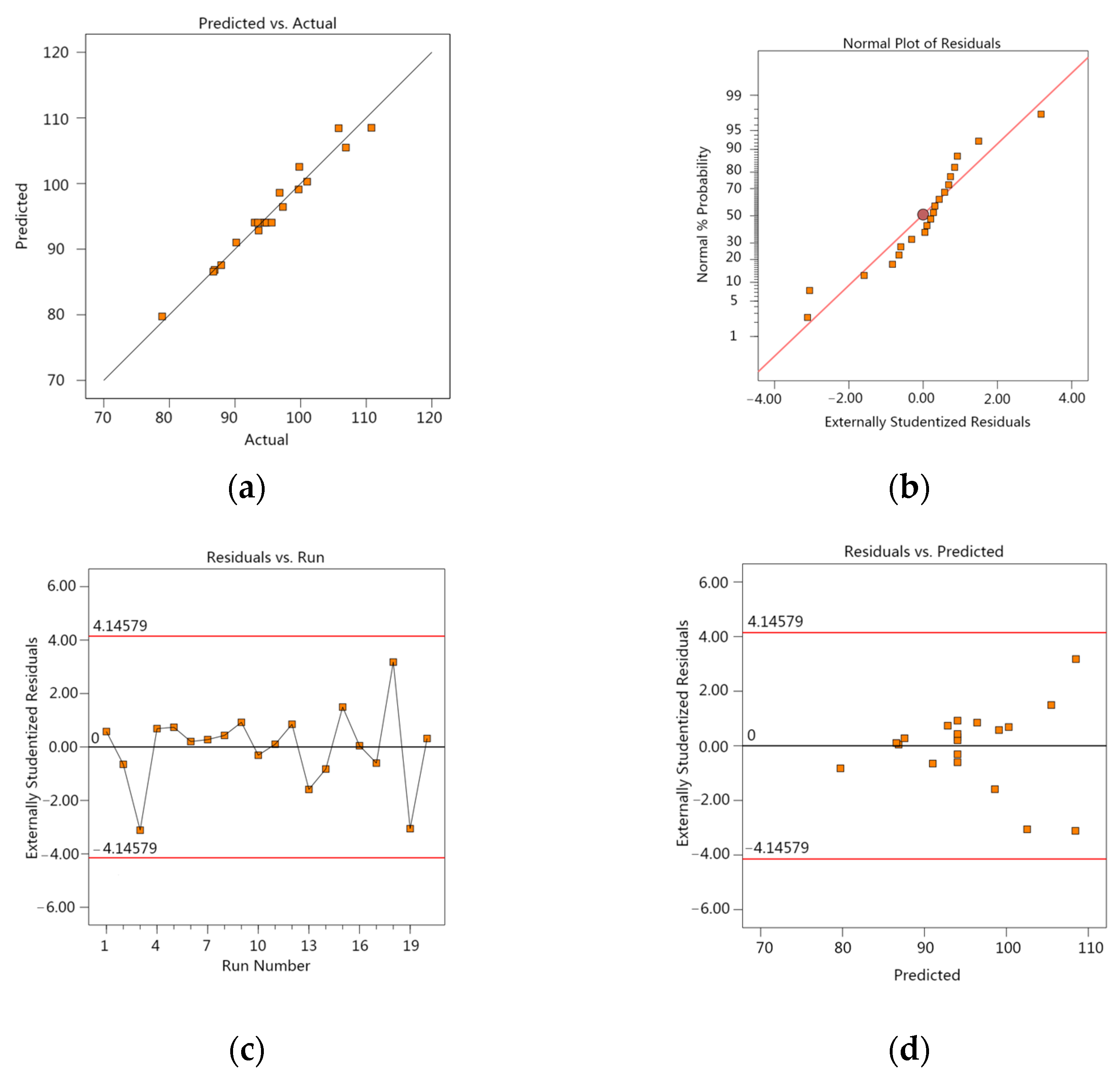
The residuals are the values fitted by the regression model subtracted from the experimental measurements. The smaller the residuals, the more accurately the regression model describes the experimental results. Figure 5a shows the relationship between the experimental values and the response prediction values. From the ideal linear distribution curve, we can see that the experimental and simulated values are basically distributed along a straight line, indicating that the experimental and simulated values are highly fitted. A normal plot of the experimental residuals can be used to determine the fit of the model, as shown in Figure 5b, which shows the fit of the residuals to the standard deviation. If the distribution of points on the plot is a straight line, the residuals are normally distributed. As can be seen from the figure, most of the experimental values fall on the predicted values in a linear distribution, indicating that the model fits the actual results well. Figure 5c,d shows the relationship between the residuals and the predicted values. The points in the diagnostic plot that are beyond the upper and lower boundary lines are anomalies, and these anomalies can indicate whether the model has large deviations. It can be seen from the figure that no points are located outside the boundary line, indicating that the model and the data match. Moreover, there are no large interference points in the model points, and the distribution of model points is also concentrated, so the model diagnostic plot results match the ANOVA data.
Response surfaces are used to analyze the interaction between the factors and the optimal response values at the optimal factor conditions. Using Design-Expert 13.0, 3D surface plots of the response values were obtained, and the contour lines were circular for insignificant interaction of the two factors and elliptical for significant interaction. The melting time of PCM in a spherical thermal storage unit is affected by the number of pin fins, the water bath temperature, and the content of CuO nanoparticles, all three of which have a synergistic effect on the complete melting time.
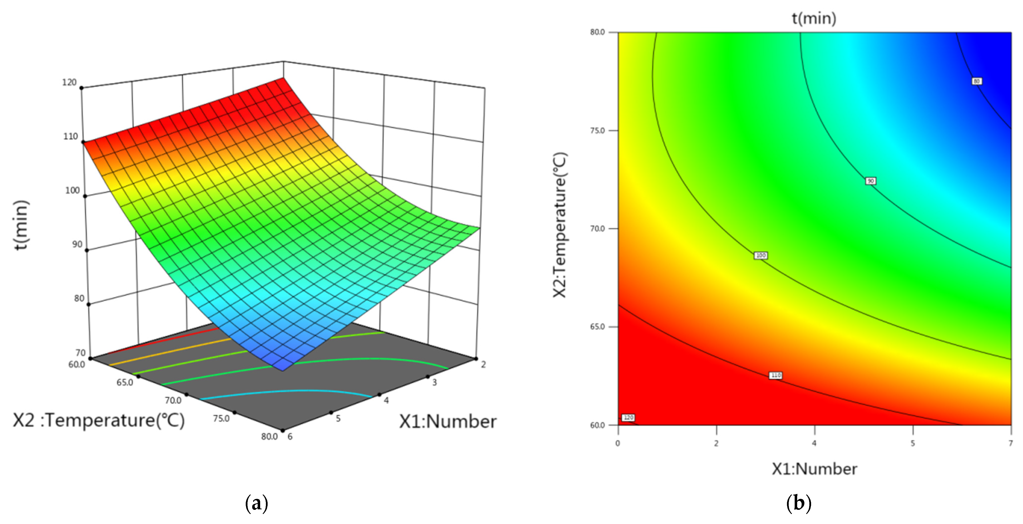
Figure 6 shows the effect of the number of pin fins and the water bath temperature on the melting time. The complete melting time decreases with increasing the number of pin fins and increases with decreasing the water bath temperature, and the water bath temperature has a greater effect on the melting time than the number of pin fins. This is because the melting of PCM is mainly influenced by temperature; the higher the external ambient temperature, the faster the PCM reaches the phase change point. Therefore, if the water bath temperature is high, the heat that can be absorbed by the PCM in the spherical unit increases; the melting rate is faster, and the melting time decreases. During the melting of the phase change material, the melting of the material in the units is faster because of the large temperature difference between the inner wall of the sphere and the solid phase change material, and the heat transfer is mainly heat conduction. As melting proceeds, the thickness of the liquid PCM layer increases, leading to an increase in thermal resistance and resulting in a gradual decrease in the melting rate. At this point, the addition of internal pin ribs is equivalent to increasing the heat transfer area in contact with the inside of the sphere, which speeds up the melting process to a certain extent and shortens the melting time.
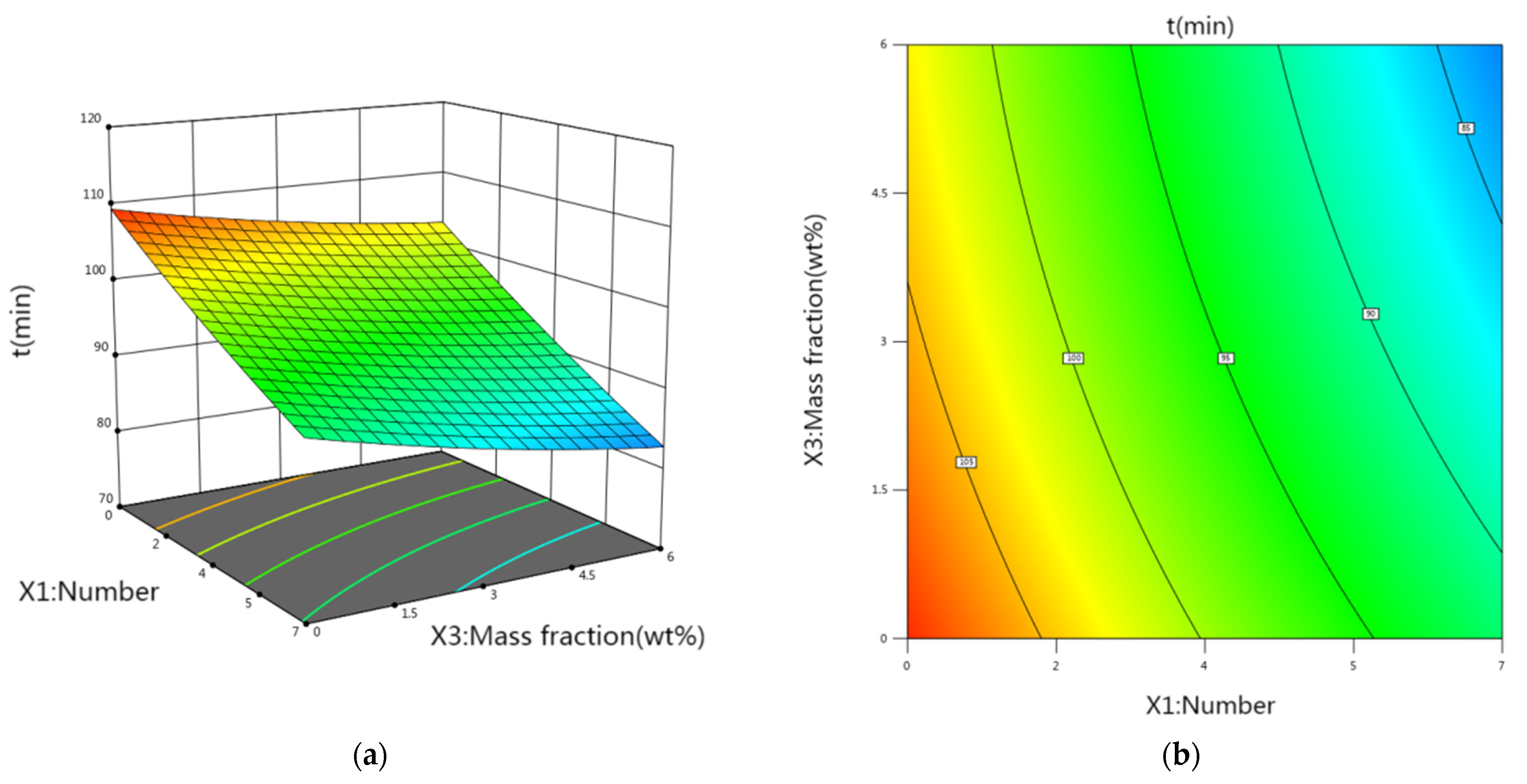
Figure 7 shows the interaction effect of the number of pin fins and the mass fraction of CuO nanoparticles, which is not significant, as shown by the circular shape of the contour plot. From Equation (2), it is clear that the number of pin fins has a greater effect on the melting time of PCM than the CuO nanoparticles content. The melting process of PCM within an externally heated spherical unit is quite complex. The unmelted solid moves because of the density difference between the solid and liquid phases, and typically, contact melting occurs at the bottom of the spherical unit because of the sinking of the heavier solid PCM. At this time, adding pin fins inside the spherical unit speeds up the melting of the internal PCM, and the more pin fins, the stronger the internal heat transfer effect, which correspondingly shortens the melting time of the PCM.
The increase in water bath temperature and the increase of CuO nanoparticles content in Figure 8 both accelerate the melting of PCM within the spherical thermal storage unit accordingly. The addition of CuO nanoparticles increases the thermal conductivity of PCM and enhances the melting heat transfer within the spherical thermal storage unit. However, the change in thermal conductivity has a relatively small effect on the melting time compared to the increase in water bath temperature.
The main objective of optimization using the response surface method is to obtain the shortest melting time. Within the range of values of the three factors, the optimum combination is chosen such that the value of melting time t is minimized. Optimization analysis of the system was carried out using Design-Expert software to obtain the optimum level of influence factors of the system as well as the optimum melting time t.
The predicted value of t was 79.7 min, and the optimal level of each influence factor was obtained from the optimization analysis: N = 6, T = 75 °C, and M = 5 wt%. In this study, response surface methodology was applied to simulate and optimize the operational impact parameters of the melting process in a spherical thermal storage unit with a minimum number of experiments, and the mathematical analysis of variance of the response surface model verified the accuracy of the model. Experiments showed that the response surface method is accurate and reliable for optimizing the operational parameters of PCM melting in spherical thermal storage units.
4. Conclusions
In this study, by building an experimental system for melting spherical heat storage units, selecting the number of pin fins, water bath temperature, and the content of CuO nanoparticles added in paraffin as variables and the melting time of composite PCM as the target value, the following conclusions were obtained using the response surface methodology to optimize the target value:
- (1)
- CCD was used to design the experimental conditions, and the data were imported into Design-Expert software to obtain the quadratic polynomial regression model of melting time. The analysis of variance showed that the regression model was significant, and the comparison analysis between the experimental and predicted values of melting time further proved that the obtained model had high reliability in fitting the melting time throughout the experimental design range.
- (2)
- The effect of the interaction between the factors on the melting time was analyzed using the response surface methodology. Among them, the water bath temperature has a large effect on the response value of PCM melting time in the spherical heat storage unit, and the interaction between the water bath temperature and the number of pin fins has the most significant effect on the melting time. The addition of CuO nanoparticles enhances heat transfer, but the effect is not particularly significant compared to the other two influencing parameters.
- (3)
- Using the optimal module of Design-Expert software, the optimal operating conditions of the system were obtained as follows: six pin fins were added to the spherical thermal storage unit, the water bath temperature was 75 °C, the mass fraction of CuO nanoparticles was 5 wt%, and the melting time of PCM was the shortest, 79.7 min. Using the response surface method, a model for predicting the melting time was further developed, and the results of this study are useful for the design of the spherical thermal storage unit. The results of this study will have a guiding significance for the design of spherical thermal storage units.
Computational analysis using the RSM is used to improve and optimize the statistical properties of the optimization objective to some extent. This research has achieved some results; however, there is still some distance from the practical application. The spherical phase change heat storage unit is not used alone in practical applications, and subsequent research should continue to explore other influencing factors that may affect the heat storage and release performance of the spherical phase change heat storage unit for in-depth study.
Author Contributions
Conceptualization, R.T.; methodology, L.L.; software, L.L.; validation, X.G.; formal analysis, R.T.; investigation, Y.Z.; resources, R.T.; data curation, L.L.; writing—original draft preparation, L.L.; writing—review and editing, R.T.; visualization, X.G.; supervision, Y.Z.; project administration, L.L.; funding acquisition, X.G. All authors have read and agreed to the published version of the manuscript.
Funding
This research was funded by the Inner Mongolia Autonomous Region Natural Science Fund, grant number 2023QN05039 and the Scientific Research Projection of Higher Schools of Inner Mongolia, grant number NJZY23115.
Institutional Review Board Statement
Not applicable.
Informed Consent Statement
Not applicable.
Data Availability Statement
The data presented in this study are available on request from the corresponding author.
Conflicts of Interest
The authors declare no conflict of interest.
References
- Du, K.; Calautit, J.; Wang, Z.; Wu, Y.; Liu, H. A review of the applications of phase change materials in cooling, heating and power generation in different temperature ranges. Appl. Energy 2018, 220, 242–273. [Google Scholar] [CrossRef]
- Jesumathy, S.; Udayakumar, M.; Suresh, S. Experimental study of enhanced heat transfer by addition of CuO nanoparticle. Heat Mass Transf. 2012, 48, 965–978. [Google Scholar] [CrossRef]
- Wang, J.; Li, Y.X.; Wang, Y.; Yang, L.; Kong, X.F.; Sunden, B. Experimental investigation of heat transfer performance of a heat pipe combined with thermal energy storage materials of CuO-paraffin nanocomposites. Solar Energy 2020, 211, 928–937. [Google Scholar] [CrossRef]
- Nourani, M.; Hamdami, N.; Keramat, J.; Moheb, A.; Shahedi, M. Thermal behavior of paraffin-nano-Al2O3 stabilized by sodium stearoyl lactylate as a stable phase change material with high thermal conductivity. Renew. Energy 2016, 88, 474–482. [Google Scholar] [CrossRef]
- Yadav, C.; Sahoo, R.R. Thermal analysis comparison of nano-additive PCM-based engine waste heat recovery thermal storage systems: An experimental study. J. Therm. Anal. Calorim. 2021, 147, 2785–2802. [Google Scholar] [CrossRef]
- Sahan, N.; Paksoy, H.O. Thermal enhancement of paraffin as a phase change material with nanomagnetite. Sol. Energy Mater. Sol. Cells 2014, 126, 56–61. [Google Scholar] [CrossRef]
- Hu, Y.W.; Shi, L.; Zhang, Z.D.; He, Y.R.; Zhu, J.Q. Magnetic regulating the phase change process of Fe3O4-paraffin wax nano-composites in a square cavity. Energy Convers. Manag. 2020, 213, 112829. [Google Scholar] [CrossRef]
- Zhang, Y.; Zheng, S.; Zhu, S.; Ma, J.; Sun, Z.; Farid, M. Evaluation of paraffin infiltrated in various porous silica matrices as shape-stabilized phase change materials for thermal energy storage. Energy Convers. Manag. 2018, 171, 361–370. [Google Scholar] [CrossRef]
- Kumar, P.M.; Mylsamy, K.; Saravanakumar, P.T. Experimental investigations on thermal properties of nano-SiO2/paraffin phase change material (PCM) for solar thermal energy storage applications. Energy Source Part A-Recovery Util. Environ.-Ronmental Eff. 2019, 42, 2420–2433. [Google Scholar]
- Tian, B.; Yang, W.; Luo, L.; Wang, J.; Zhang, K.; Fan, J.; Wu, J.; Xing, T. Synergistic enhancement of thermal conductivity for expanded graphite and carbon fiber in paraffin/EVA form-stable phase change materials. Sol. Energy 2016, 127, 48–55. [Google Scholar] [CrossRef]
- Chen, M.; He, Y.; Ye, Q.; Zhang, Z.; Hu, Y. Solar thermal conversion and thermal energy storage of CuO/Paraffin phase change composites. Int. J. Heat Mass Transf. 2019, 130, 1133–1140. [Google Scholar] [CrossRef]
- Lin, S.C.; Al-Kayiem, H.H. Evaluation of copper nanoparticles—Paraffin wax compositions for solar thermal energy storage. Sol. Energy 2016, 132, 267–278. [Google Scholar] [CrossRef]
- Kumar, P.M.; Mylsamy, K.; Prakash, K.B.; Nithish, M.; Anandkumar, R. Investigating thermal properties of Nanoparticle Dispersed Paraffin(NDP)as phase change material for thermal energy storage. Mater. Today Proc. 2020, 45, 745–750. [Google Scholar] [CrossRef]
- Pasupathi, M.K.; Alagar, K.; Mm, M.; Aritra, G. Characterization of Hybrid-nano/Paraffin Organic Phase Change Material for Thermal Energy Storage Applications in Solar Thermal Systems. Energies 2020, 13, 5079. [Google Scholar] [CrossRef]
- Li, W.; Wang, Y.-H.; Kong, C.-C. Experimental study on melting/solidification and thermal conductivity enhancement of phase change material inside a sphere. Int. Commun. Heat Mass Transf. 2016, 68, 276–282. [Google Scholar] [CrossRef]
- Ismail, M.; Alkhazaleh, A.H.; Masri, J.; Ali, A.M.; Ali, M. Experimental and numerical analysis of paraffin waxes during solidifi-cation inside spherical capsules. Therm. Sci. Eng. Prog. 2021, 26, 101095. [Google Scholar] [CrossRef]
- Asker, M.; Ganjehsarabi, H.; Coban, M.T. Numerical investigation of inward solidification inside spherical capsule by using temperature transforming method. Ain Shams Eng. J. 2018, 9, 537–547. [Google Scholar] [CrossRef] [Green Version]
- Fan, L.; Khodadadi, J.M. Thermal conductivity enhancement of phase change materials for thermal energy storage: A review. Renew. Sustain. Energy Rev. 2011, 15, 24–46. [Google Scholar] [CrossRef]
- Li, J.; Abdulghani, Z.R.; Alghamdi, M.N.; Sharma, K.; Niyas, H.; Moria, H.; Arsalanloo, A. Effect of twisted fins on the melting performance of PCM in a latent heat thermal energy storage system in vertical and horizontal orientations: Energy and exergy analysis. Appl. Therm. Eng. 2023, 219, 119489. [Google Scholar] [CrossRef]
- Koizumi, H. Time and spatial heat transfer performance around an isothermally heated sphere placed in a uniform, down-wardly directed flow (in relation to the enhancement of latent heat storage rate in a spherical capsule). Appl. Therm. Eng. 2004, 24, 2583–2600. [Google Scholar] [CrossRef]
- Bouguila, M.; Samet, A.; Ben Souf, M.A.; El Hami, A.; Haddar, M. Thermal performances of finned heat sink filled with nano-enhanced phase change materials: Design optimization and parametric study. Int. J. Heat Mass Transf. 2023, 202, 123710. [Google Scholar] [CrossRef]
- Fan, L.-W.; Zhu, Z.-Q.; Xiao, S.-L.; Liu, M.-J.; Lu, H.; Zeng, Y.; Yu, Z.-T.; Cen, K.-F. An experimental and numerical investigation of constrained melting heat transfer of a phase change material in a circumferentially finned spherical capsule for thermal energy storage. Appl. Therm. Eng. 2016, 100, 1063–1075. [Google Scholar] [CrossRef]
- Aziz, S.; Amin, N.; Majid, M.A.; Belusko, M.; Bruno, F. CFD simulation of a TES tank comprising a PCM encapsulated in sphere with heat transfer enhancement. Appl. Therm. Eng. 2018, 143, 1085–1092. [Google Scholar] [CrossRef]
- Premnath, D.; Chandrasekaran, P.; Subramanian, L.R.G.; Senthil, R. Experimental performance of a finned spherical container in cold thermal storage for tropical buildings. Environ. Sci. Pollut. Res. 2022, 29, 76793–76804. [Google Scholar] [CrossRef]
- Meghari, Z.; Bouhal, T.; Benghoulam, M.; El Rhafiki, T.; El Khattabi, E.M.; Doghmi, H.; Mohammed, O.J. Numerical simulation of a phase change material in a spherical capsule with a hollow fin. J. Energy Storage 2021, 43, 103024. [Google Scholar] [CrossRef]
- Sharma, A.; Kothari, R.; Sahu, S.K. Effect of fin location on constrained melting heat transfer of phase change material in a spherical capsule: A numerical study. J. Energy Storage 2022, 52, 104922. [Google Scholar] [CrossRef]
- Lou, X.; Wang, H.; Xiang, H. Solidification performance enhancement of encapsulated ice storage system by fins and copper foam. Int. J. Refrig. 2022, 134, 293–303. [Google Scholar] [CrossRef]
- Amin, N.A.M.; Bruno, F.; Belusko, M. Investigation of Conducting Pins in Sphere Filled with Phase Change Material for Enhancing Heat Transfer in Thermal Energy Storage. Adv. Mater. Res. 2012, 472–475, 1693–1697. [Google Scholar] [CrossRef]
- Sun, B.; Sun, M.; Gao, L.; Che, D.; Deng, Y. Thermal performance analysis and optimization of a double-layer spherical phase-change material capsule with annular fins. J. Energy Storage 2023, 57, 106280. [Google Scholar] [CrossRef]
- Doss, P.; Ponnusamy, C.; Ramachandran, G.S.L. Predictive modeling of solidification characteristics of a phase change material in a metallic spherical capsule fitted with fins of different lengths. Energy Sources Part A Recover. Util. Environ. Eff. 2020, 1–14. [Google Scholar] [CrossRef]
Figure 1.
Curve of latent heat of phase change materials using DSC.

Figure 2.
Distribution of fins inside the phase change heat storage sphere.

Figure 3.
Diagram of melting experiment system.

Figure 4.
Temperature change at measurement point 3 in the heat storage unit: (a) various numbers of fins; (b) different mass fractions of CuO.
Figure 4.
Temperature change at measurement point 3 in the heat storage unit: (a) various numbers of fins; (b) different mass fractions of CuO.

Figure 5.
The diagnostic plots of RSM models: (a) actual vs. predicted values for complete melting time; (b) normal probability plots; (c) residuals vs. experimental runs; (d) residuals vs. predicted values.
Figure 5.
The diagnostic plots of RSM models: (a) actual vs. predicted values for complete melting time; (b) normal probability plots; (c) residuals vs. experimental runs; (d) residuals vs. predicted values.

Figure 6.
Response surface (a) and contour plot (b) of the number of pin fins and water bath temperature on the complete melting time.
Figure 6.
Response surface (a) and contour plot (b) of the number of pin fins and water bath temperature on the complete melting time.

Figure 7.
Response surface (a) and contour plot (b) of the number of pin fins and mass fraction of CuO nanoparticles on the complete melting time.
Figure 7.
Response surface (a) and contour plot (b) of the number of pin fins and mass fraction of CuO nanoparticles on the complete melting time.

Figure 8.
Response surface (a) and contour plot (b) of water bath temperature and CuO nanoparticles mass fraction on the complete melting time.
Figure 8.
Response surface (a) and contour plot (b) of water bath temperature and CuO nanoparticles mass fraction on the complete melting time.


Table 1.
Actual and coded values of the independent variables used for the experimental design.
| Variable | Symbol | Real Values of Code Levels | ||||
|---|---|---|---|---|---|---|
| −α | −1 | 0 | 1 | −α | ||
| N | X1 | 1 | 2 | 4 | 6 | 7 |
| T (°C) | X2 | 62 | 65 | 70 | 75 | 78 |
| M (wt%) | X3 | 0 | 1 | 3 | 5 | 6 |
Table 2.
CCD experimental design and the obtained responses.
| Run Number | Design Factors | Responses | |||||
|---|---|---|---|---|---|---|---|
| X1 | X2 | X3 | t (min) | ||||
| N | T (°C) | M (wt%) | |||||
| No. | Actual | Code | Actual | Code | Actual | Code | |
| 1 | 6 | +1 | 65 | −1 | 1 | −1 | 101.0 |
| 2 | 6 | +1 | 65 | −1 | 5 | +1 | 97.3 |
| 3 | 6 | +1 | 75 | +1 | 1 | −1 | 86.9 |
| 4 | 6 | +1 | 75 | +1 | 5 | +1 | 78.9 |
| 5 | 2 | −1 | 65 | −1 | 1 | −1 | 110.8 |
| 6 | 2 | −1 | 65 | −1 | 5 | +1 | 106.9 |
| 7 | 2 | −1 | 75 | +1 | 1 | −1 | 99.7 |
| 8 | 2 | −1 | 75 | +1 | 5 | +1 | 93.6 |
| 9 | 7 | +1.68 | 70 | 0 | 3 | 0 | 86.7 |
| 10 | 1 | −1.68 | 70 | 0 | 3 | 0 | 99.8 |
| 11 | 4 | 0 | 78 | +1.68 | 3 | 0 | 87.9 |
| 12 | 4 | 0 | 62 | −1.68 | 3 | 0 | 105.8 |
| 13 | 4 | 0 | 70 | 0 | 6 | +1.68 | 99.7 |
| 14 | 4 | 0 | 70 | 0 | 0 | −1.68 | 96.8 |
| 15 | 4 | 0 | 70 | 0 | 3 | 0 | 94.4 |
| 16 | 4 | 0 | 70 | 0 | 3 | 0 | 94.8 |
| 17 | 4 | 0 | 70 | 0 | 3 | 0 | 95.6 |
| 18 | 4 | 0 | 70 | 0 | 3 | 0 | 93.5 |
| 19 | 4 | 0 | 70 | 0 | 3 | 0 | 93.0 |
| 20 | 4 | 0 | 70 | 0 | 3 | 0 | 94.6 |
Table 3.
Uncertainty analysis.
| Quantities | Uncertainties |
|---|---|
| Diameter | ±0.02 mm |
| Temperature | ±0.5 °C |
| Mass | ±0.001 g |
Table 4.
Results of ANOVA.
| Source | Sum of Square | Degree of Freedom | Mean Square | F-Value | p-Value | R2 | Adjusted R2 | Adequate Precision |
|---|---|---|---|---|---|---|---|---|
| Model | 1036.96 | 9 | 115.22 | 34.37 | <0.0001 | 0.9687 | 0.9405 | 22.2023 |
| Error | 4.37 | 5 | 0.8737 | - | - | - | - | - |
| Total | 1070.48 | 19 | - | - | - | - | - | - |
Disclaimer/Publisher’s Note: The statements, opinions and data contained in all publications are solely those of the individual author(s) and contributor(s) and not of MDPI and/or the editor(s). MDPI and/or the editor(s) disclaim responsibility for any injury to people or property resulting from any ideas, methods, instructions or products referred to in the content. |
© 2023 by the authors. Licensee MDPI, Basel, Switzerland. This article is an open access article distributed under the terms and conditions of the Creative Commons Attribution (CC BY) license (https://creativecommons.org/licenses/by/4.0/).
Share and Cite
MDPI and ACS Style
Lu, L.; Tian, R.; Gong, X.; Zhao, Y. Enhanced Heat Transfer Study of Spherical Heat Storage Based on Response Surface Methodology. Appl. Sci. 2023, 13, 8595. https://0-doi-org.brum.beds.ac.uk/10.3390/app13158595
AMA Style
Lu L, Tian R, Gong X, Zhao Y. Enhanced Heat Transfer Study of Spherical Heat Storage Based on Response Surface Methodology. Applied Sciences. 2023; 13(15):8595. https://0-doi-org.brum.beds.ac.uk/10.3390/app13158595
Chicago/Turabian StyleLu, Liwei, Rui Tian, Xuan Gong, and Yuanxing Zhao. 2023. "Enhanced Heat Transfer Study of Spherical Heat Storage Based on Response Surface Methodology" Applied Sciences 13, no. 15: 8595. https://0-doi-org.brum.beds.ac.uk/10.3390/app13158595
Note that from the first issue of 2016, this journal uses article numbers instead of page numbers. See further details here.