Article

Research and Application of Steam Condensation Heat Transfer Model Containing Noncondensable Gas on a Wall Surface

1
CNNC Key Laboratory on Severe Accident in Nuclear Power Safety, China Nuclear Power Engineering Co., Ltd., No 117 Xisanhuan North Road, Beijing 100084, China
2
State Key Laboratory of Multiphase Flow in Power Engineering, Xi’an Jiaotong University, Xian-Ning West Road 28#, Xi’an 710049, China
*
Author to whom correspondence should be addressed.
Submission received: 16 August 2023 / Revised: 15 September 2023 / Accepted: 19 September 2023 / Published: 21 September 2023
(This article belongs to the Special Issue Flow and Heat Transfer Research in Multiphase Flow and Porous Media)

Abstract

:
Steam condensation plays an important role in various engineering processes due to its excellent heat transfer performance. However, condensation in the presence of noncondensable gas has attracted great attention in recent years since noncondensable gas will have a negative effect on condensation heat transfer. The present study proposes a comprehensive model coupled with convective heat transfer, liquid film heat transfer and steam condensation for the heat transfer of condensation with noncondensable gas and uses it in the Program Integrated for Severe Accident Analysis (PISAA) for a nuclear power plant. The condensation heat transfer model has good universality, the calculation process is stable with less iteration and a fast convergence and it is verified and validated by comparing the simulation results of the PISAA and those from traditional containment analysis codes, as well the experiments from the Wisconsin condensation tests; then, a sensitivity analysis for the parameters of the heat transfer coefficient is performed. The validation results show that the average error of the condensation heat transfer coefficient is approximately 10%, and the maximum error does not exceed 30%. The deviation from the experimental data is limited in the acceptable range, which could fulfill the requirement for the analysis of containment accidents in nuclear power plants.

1. Introduction

Steam condensation heat transfer is a common phenomenon in daily life and is widely used in the chemical industry, refrigeration, energy and other engineering processes. However, steam is always mixed with some gases that may not condense under different working conditions, while noncondensable gas can have a negative effect on condensation heat transfer [1,2,3,4].
The presence of noncondensable gases (such as air) in steam, even at very low levels, can significantly worsen heat transfer in applications [4]. Taking nuclear power plant accidents as an example, the release of high-temperature and high-pressure gas from the primary system will result in a sudden increase in temperature and pressure in containment, thereby endangering the structural integrity of the containment. The condensation heat transfer of high-temperature and high-pressure steam on the containment wall is an important method to remove internal heat; however, the presence of any noncondensable gas, such as air, can greatly affect the steam condensation efficiency, lead to a deterioration of heat transfer performance and complicate the overall process [2,3]. Consequently, it is of great significance to analyze the factors affecting condensation so as to improve the calculation accuracy of condensation heat transfer.
The condensation process of steam mixed with noncondensable gas is very complicated, as it involves not only the exchange and transfer of mass, energy and momentum between steam and condensed liquid, but also the exchange and diffusion of energy and momentum between steam and noncondensable gas [1]. So far, the research on this process mainly consists of experimental studies [5,6,7,8,9,10,11,12,13,14,15] and theoretical analyses [16,17,18,19,20,21,22,23,24,25,26,27,28].
In the experimental aspect, researchers have paid much attention to the heat transfer characteristics of condensation under various working conditions [6,7,10,14,15], as well as heat transfer enhancement using variant means. They conducted many experiments and obtained different heat transfer correlations, like the commonly used Uchida [7], Tagami [8] and Dehbi [9] models and so on, and correlations were made with the heat transfer rate via gas concentration, pressure, temperature, surface subcooling, and some other parameters. However, the main obstacle is that most correlations are not universally valid, and each empirical relation has a very strict application condition.
At the same time, a numerical calculation has become an important means to explain condensation phenomena by means of both lumped parameter codes and 3D CFD codes [20,21]; in contrast to the experiments, the numerical method can obtain more detailed information about the flow characteristics and gas concentration distribution. And many factors have also been considered to affect the condensation efficiency [25,26,27,28] like the geometrical parameter, thickness of film, suction factor and so on, but for pure theoretical numerical calculations, the calculation process is complicated and difficult to understand, and at the same time, too many iterations lead to a divergence of the calculation results.
In a nuclear power plant, the condensation process of steam with noncondensable gas on the surface of a heat structure is accompanied by an intense heat and mass transfer, which directly affects the spatial distribution of the temperature and pressure in containment, and then affects the safe operation of the integrated reactor [4]. This paper analyzes and discusses this phenomenon, proposes a condensation calculation model, and applies this calculation model to the integral analysis code of the PISAA (Program Integrated for Severe Accident Analysis) for severe accidents. By conducting specific working conditions, the wall condensation model in the PISAA is compared and verified with the mainstream containment thermal hydraulic codes. Additionally, the calculation results of the model are validated by comparing the data with those of the Wisconsin condensation experiment [15]. Finally, a brief sensitivity analysis is performed on the condensation heat transfer model, which further improves the accuracy of the condensation heat transfer calculation.

2. Condensation Heat Transfer Model

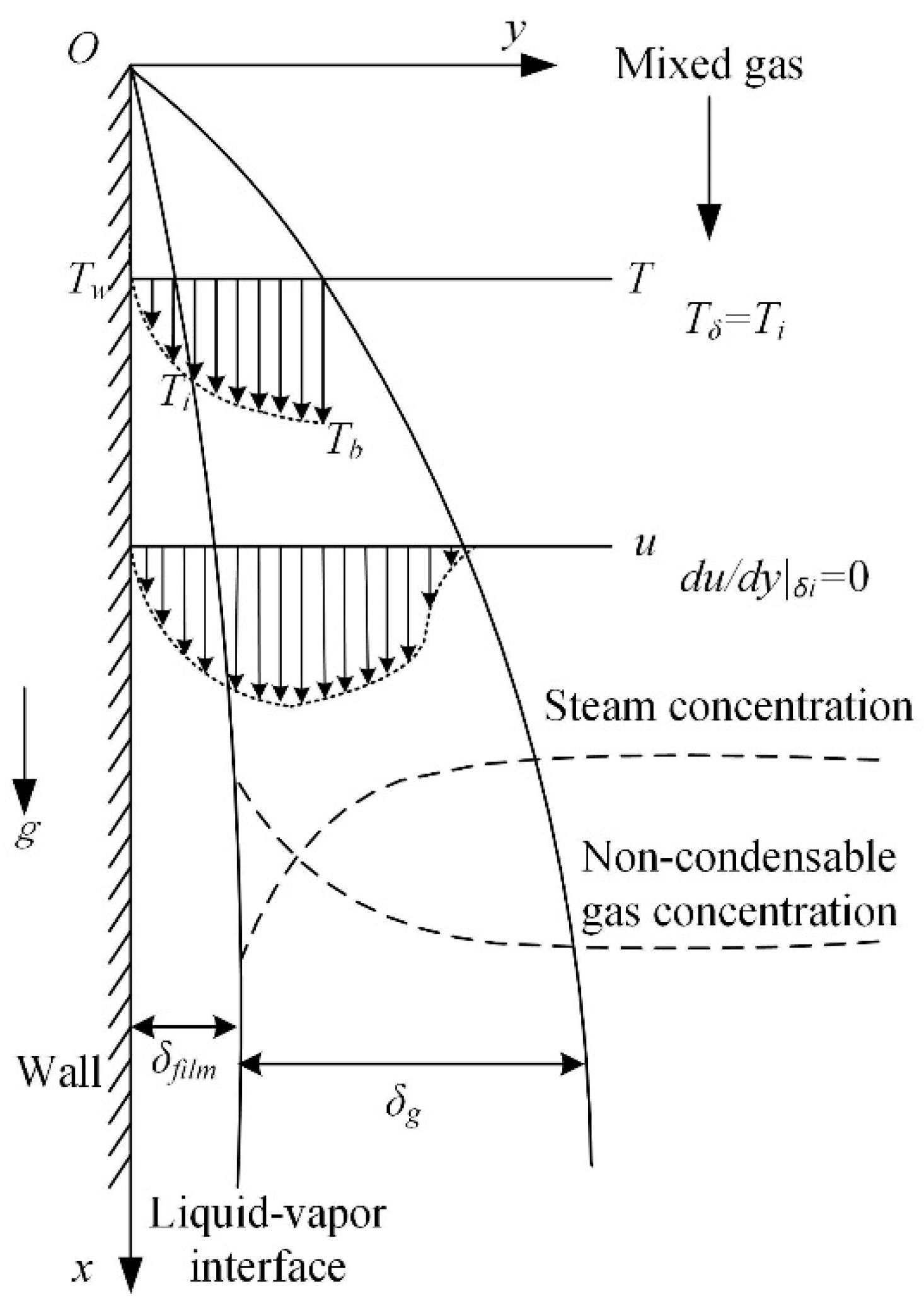
Figure 1 shows the condensation model of steam with noncondensable gas on the vertical wall. For the condensation process containing noncondensable gas, when the wall temperature is lower than the saturation temperature corresponding to the partial pressure of steam in the mixture, the saturated steam will condensate on the wall and form a liquid film. Meanwhile, the liquid film flows along the direction of gravity, and its flow state changes from laminar to turbulent as the liquid film thickness increases [1,14]. Due to the accumulation of noncondensable gas on the surface of the liquid film, when the mixture moves towards the interface, the aggregation of noncondensable gas molecules causes an increase in the gas’s partial pressure and forms the driving force of the reverse diffusion of noncondensable gas to the mainstream gas. While the steam condenses and its partial pressure decreases below that of the steam in the mainstream gas at the interface between the phases, this pressure differential promotes the diffusion of steam towards the interface, which is facilitated by the pressure gradient. The diffusion of steam towards the condensing surface and the noncondensable gases towards the mainstream gas maintain a dynamic equilibrium with a constant total pressure [12]. Under the influence of two conditions, the state parameters at the phase interface cannot be determined.
The steam in the gas mixture is transferred to the wall by means of mass diffusion, which requires it to pass through the highly concentrated noncondensable gas layer that gathers on the surface of the condensate film, and then condenses on the surface and releases latent heat. The heat transfer resistance of the whole steam condensation is mainly divided into three parts, and the steam transfers the heat to the surface of the liquid film by means of condensation and convection, respectively, that is, there is condensation thermal resistance and convection thermal resistance, and further heat passes through the liquid film thermal resistance and finally reaches the condensing wall.
Correspondingly, the total heat transfer coefficient is determined by the thermal resistance of the three aspects above: the liquid film heat transfer coefficient hfilm determined by TiTw, the convective heat transfer coefficient hconv and the condensation heat transfer coefficient hcond determined by Tg − Ti. The energy conservation equation is as follows [29]:
q h tot = q h film + q h conv + h cond
h tot ( T g T w ) = h film ( T i T w ) = ( h conv + h cond ) ( T g T i )
where: q—total heat transfer flux;
htot—total heat transfer coefficient;
hfilm—film heat transfer coefficient;
hconv—convective heat transfer coefficient;
hcond—steam condensation heat transfer coefficient;
Tg—mixture gas temperature;
Ti—interface temperature;
Tw—surface temperature of the plate.
As can be seen from Equation (2), the total heat transfer coefficient htot is related to the liquid film heat transfer coefficient hfilm, convective heat transfer coefficient hconv and steam condensation heat transfer coefficient hcond, as well as the mixture gas temperature, interface temperature and surface temperature. So, in order to obtain the final total heat transfer coefficient, it is necessary to solve the hfilm, hconv and hcond one by one, and determine the interface temperature Ti.
For the film heat transfer coefficient hfilm, generally, the Nusselt theory and the modified equation based on the Nusselt theory are widely used to calculate the heat transfer coefficient of liquid film. However, according to the Nusselt theory, the liquid film is assumed to be laminar flow; when the vertical surface is too long, the liquid film fully develops, and the flow in the liquid film gradually changes from laminar flow to wavy laminar flow and then to turbulence flow. Using the solution based on the Nusselt theory will simply produce a certain deviation, so the following formula is adopted for laminar flow when Re < 30 [29]:
R e = 3.78 [ k l L ( T i T w ) μ l h fg * ( ν l 2 / g ) 1 / 3 ] 3 / 4 R e <   30
Kutateladze’s relation is adopted for wavy laminar flow when 30 ≤ Re < 1800:
Re = [ 3.70 k l L ( T i T w ) μ l h fg * ( ν l 2 / g ) 1 / 3 + 4.81 ] 0.820   30 Re < 1800
Labuntsov’s relation is adopted for turbulent condensate flow when Re ≥ 1800:
Re = [ 0.069 k l L ( T i T w ) μ l h fg * ( ν l 2 / g ) 1 / 3 Pr 0.5 151 Pr 0.5 + 253 ] 4 / 3 Re 1800
where: kl—thermal conductivity of the liquid;
L—height of the vertical plate;
μ l —dynamic viscosity of the liquid;
v l —kinematic viscosity of the liquid;
g—gravitational acceleration;
Pr—Prandtl number.
Actually, the condensation process is cooled further to some average temperature between Ti and Tw, releasing more heat in the process. Therefore, the actual heat transfer will be larger. Rohsenow suggested that the cooling of the liquid below the saturation temperature can be accounted for the modified latent heat of vaporization h fg * , defined as h f g * = h fg + 0.68 c p , l ( T i T w ) , where c p , l is the specific heat of the liquid at the average film temperature.
After calculating Re, the liquid film heat transfer coefficient hfilm is finally calculated as follows:
h film = R e μ l h fg * 4 L ( T i - T w )
For the convective heat transfer coefficient hconv, according to the numerical correlation of the convective heat transfer similarity criterion without considering the convective heat transfer coefficient under the influence of normal mass transfer, it can be calculated as follows:
h conv = N u k / l
The Nu number in the equation above refers to the relationship between turbulent natural convection and forced convection over a flat plate according to different convection forms:
N u F C = 0.037 R e 0.8 P r 1 / 3
N u N C = 0.13 ( G r P r ) 1 / 3
For mixed convection, the following equation is adopted [29]:
N u mixed n = N u FC n ± N u NC n
where N u mixed is the Nusselt number for the mixed flow, and N u FC and N u NC are the Nusselt number calculated via forced convection correlation and natural convection correlation under given conditions, respectively. A positive sign was taken when the two flow directions were the same, a negative sign was taken when they were opposite, and for an uncertain flow direction, the minimum value of N u mixed n was adopted via conservative estimation. The exponent, n, is usually 3.
For the steam condensation heat transfer coefficient hcond, the Kreith model based on the principle of heat/mass transfer analogy (HMTA) in the diffusion boundary layer was used for calculation [13,29]:
m = h conv k D steam M steam P R T ( P steam , i P steam , g ) P non , avg ( S c P r ) 1 / 3
where: m —steam condensation rate per unit area;
k—thermal conductivity of mixture in diffusion boundary layer;
D steam —steam diffusion coefficient;
M steam —molar mass of steam;
P —total mixture pressure;
P steam , i —partial pressure of steam at phase interface;
P steam , g —partial pressure of steam in main flow;
P non , avg —mean partial pressure of noncondensable gas in gas phase;
Sc—Schmidt number.
In calculation, it is assumed that the steam at the interface is saturated, and that film condensation occurs on the wall surface. After condensation, the liquid film is uniformly attached to the wall surface. At the same time, the thickness of the film can be expressed by combining the condensing mass quality and density of the condensed water and the heat transfer area of the wall surface.
After calculating the condensation rate, the heat transfer coefficient of condensation is further calculated as follows:
q cond = m h fg *
h cond = q cond T g T i = m h fg * T g T i
For the total heat transfer coefficient htot, since the calculations of hfilm, hconv and hcond all require the interface temperature Ti in order to obtain the total heat transfer coefficient htot, the liquid film heat transfer coefficient, convective heat transfer coefficient and steam condensation heat transfer coefficient need to be calculated successively by assuming the initial value of the liquid film surface temperature, and then a new Ti is obtained through the equations above, and an iteration is performed until the difference between the new and old interface temperatures Ti reaches an acceptable error; then, the final interface temperature Ti is obtained. After that, the total heat transfer coefficient htot can be obtained.

3. Verification and Validation of Condensation Heat Transfer Model

After the construction of the condensation model, it is necessary to carry out further verification and validation of the model. For verification, this paper uses the code-to-code method to model and calculate the same example by using the PISAA and traditional thermal hydraulic codes, respectively, and then compares the calculated results from the different codes. For validation, this paper creates a calculation example by referring to the Wisconsin condensation experiment, and then compares the calculated results with the experimental data.

3.1. Model Verification using Traditional Containment Analysis Codes

By utilizing the developed heat transfer calculation model of the internal heat structure of the containment, which is implemented in the autonomous integral analysis code, PISAA, the calculation is performed using a control volume coupled with a heat structure. If the coupling between the control volume and the heat structure is in a non-equilibrium state, the heat structure serves as a heat sink and transfers heat and mass with the internal fluid until the system reaches a steady state. During the process, parameters such as the composition and state of the fluid inside the control volume, and the position, direction and boundary conditions of the heat structure are all important factors that affect the system’s ability to reach its final equilibrium state and should be taken into account, respectively, in calculation. Moreover, the developed computing code is validated by combining the parameters with the mainstream containment computing code and conducting the same case calculations. The conditions for the calculation are shown in Table 1 below.
For the above case, calculations were carried out using traditional containment analysis codes, code A, code B and PISAA, respectively. The pressure and gas temperature in the control volume, as well as the wall temperature and heat transfer coefficient of the heat structure, were analyzed sequentially, and the comparison diagrams are shown in Figure 2 below.
Figure 2 shows the variations in the pressure and gas temperature of the control volume, and the wall temperature of the heat structure when it is vertically placed inside the control volume. It can be observed from the figure that, after the process starts, heat transfer occurs between the fluid and the heat structure in the control volume due to the heat disequilibrium. The heat release from the high-temperature heat structure causes increases in the temperature and pressure of the gas inside the control volume, which gradually stabilize over time. Since the heat storage capacity of the gas in the control volume is much smaller than that of the heat structure, the temperature rise in the gas is much larger than the wall temperature of the heat structure. As can be seen from the figure, the temperature of the gas increases by about 40 K, while the wall temperature of the heat structure finally changes by less than 0.1 K.
The convective heat transfer coefficient increases significantly after the beginning of the process, because the temperature difference between the gas temperature and the wall temperature is the largest at the beginning. For the natural convection heat transfer process in a limited space, the corresponding Grashof number is the largest at this time. Meanwhile, since the qualitative temperature of the fluid is half of the sum of the gas temperature and the wall temperature of the heat structure, it is also the maximum value. As the temperature of the gas approaches the temperature of the heat structure, the heat transfer coefficient tends to be stable.
As the system gradually approaches stability, there is a certain deviation in the calculation results of the convective heat transfer coefficient for three codes. But the change trend is basically consistent and there is only a small variation in the steady-state values. The results of the model used in this paper are more similar to the results obtained from code A. After the internal parameters of the system reach a steady state, their values generally remain unchanged.

3.2. Model Validation via Wisconsin Condensation Experiment

In addition, to validate the surface condensation heat transfer model for the heat structure, the results of this paper are compared with the Wisconsin atmospheric partial condensation experimental data [15]. The Wisconsin experiment mainly studied the condensation heat transfer phenomenon in the presence of noncondensable gases. The experiment considered condensation on both vertical and horizontal flat plates in a large space. Six aluminum condensation plates, with a total length of 0.9144 m and a thickness of 0.3048 m, were installed on the top and side walls located in the upper-right corner of the container. The container was filled with humid air maintained at a constant temperature and pressure. The humid air led to the condensation of heat on the wall of the aluminum condensation plates. During the experiment, the external surface of the condensation plate was cooled using continuously subcooled water to keep the plate wall temperature constant inside the large container, and high-temperature steam was injected from the bottom of the container to maintain the initial constant temperature and pressure state under different operating conditions. By setting different initial thermal parameters, the condensation heat transfer coefficients were measured under different experimental conditions using the HFM (Heat Flux Meter) and CEB (Coolant Energy Balance) methods. Table 2 briefly lists the necessary initial parameters for each experimental condition.
In the Wisconsin experiment, two different methods were used to measure the convective heat transfer coefficient, but the uncertainty of the two measurement results was not given. Therefore, in order to improve the reliability of the experimental comparison results, the average value of the results obtained from the two measurement methods was used.
During the modeling process, one side surface of the heat structure was subjected to convection heat transfer, while the other side was kept at a constant temperature, and the air with steam was condensed on the heat structure surface. Figure 3 shows the comparison of the heat transfer coefficients between the experimental data and calculation results of the condensation for the vertical and horizontal condensing plates, respectively.
According to the initial parameters, it can be known that the mixed steam containing noncondensable gas will condense on the condensing plate. As can be seen from Figure 3, the condensation heat transfer coefficient calculated via the PISAA is basically consistent with the experimental data for all cases. However, for the conditions with relatively more noncondensable gas such as cases 1, 2, 3 and 4, the heat transfer coefficient is significantly lower than the other conditions. Taking conditions 1 and 6 of the vertical condensing plate as examples, when the molar fraction of noncondensable gas decreases from 0.795 to 0.42, the heat transfer coefficient increases from 75.8 W/m2K to 238.9 W/m2K. The heat transfer coefficient increases obviously with the decrease in noncondensable gas, which further indicates that noncondensable gas has a great influence on heat transfer.
The calculation results for the vertical condensing plate in cases 9, 10 and 11 show a slightly larger deviation from the experimental data, with the maximum difference of 29.1477%, but are still within the acceptable deviation range of engineering. The other cases show smaller deviations. The average error of the heat transfer coefficient of horizontal condensation is about 2.5481%, which is in good agreement with the experimental data. The comparison results indicate that the wall condensation model used in the PISAA can simulate the physical process of wall condensation scientifically and accurately.

4. Parameter Sensitivity Analysis

After the verification and validation of the condensation model, it is necessary to carry out an appropriate analysis for the sensitivity parameters that affect the calculation results. There are many factors that affect the condensation heat transfer coefficient of a heat structure. The setting of the system parameters and the selection of the calculation models can both cause fluctuations in the results. In order to further investigate the accuracy and reliability of the model, this paper conducted a sensitivity analysis of the code by varying the geometric parameters of the system and calculating models, respectively.

4.1. Mesh Node Independence in Heat Structure

The node division of a heat structure affects the surface temperature to a certain extent. The denser the node division, the closer the node temperature to the real situation, which will then affect the physical property parameters of the fluid. For example, in the calculation of the convective heat transfer coefficient in Equations (8) and (9), the Re, Gr and Pr numbers all depend on the physical property parameters, such as the specific heat and viscosity, which may have a certain influence on the calculation results. Therefore, the number of nodes divided in the heat structure is analyzed as a sensitive parameter in this paper.
Table 3 and Table 4 provide a detailed analysis of the influence of node numbers on the heat transfer coefficient of the condensing plate in different directions when they are divided. In this paper, the heat structure was divided into two, five and ten nodes along the heat transfer direction, respectively. After the calculation was completed, the comparison of the results revealed that the heat transfer coefficient of the heat structure’s wall was hardly influenced by the number of nodes, and the deviation of the calculation results for each case was within 5‰, which can be considered negligible. In fact, because the wall thickness of the condensing plate is small, the overall thermal conductivity and thermal resistance is small, which can make the nodes in the heat structure reach the thermal equilibrium state in a very short time; therefore, the differences caused by thermal diffusion can be completely ignored. Consequently, the number of nodes in the heat structure will not significantly affect the magnitude and range of the heat transfer coefficient.

4.2. Calculation Model for Mass Diffusivity

The physical parameters of water, steam, noncondensable gases and various materials are repeatedly used in the calculations, so the calculated values of these physical parameters affect the accuracy of the results to some extent. It can be seen from Equation (11) that the value of the mass diffusion coefficient DAB has an impact on the mass condensation rate. Different calculation models of the mass diffusion coefficient will cause a disturbance to the condensing amount of steam per unit area.
According to the principle of the heat/mass transfer analogy, combined with Equations (12) and (13), it can be seen that the condensing heat transfer rate is also further affected by DAB. Therefore, a sensitivity analysis of the mass diffusion coefficient is performed here.
When representing the mass diffusivity of steam to other mixed noncondensable gases, the Wilke and Lee model and the Fuller model were selected in this paper to calculate the mass diffusion rate of steam to a single noncondensable gas [30], and after obtaining the binary mass diffusivity, the final calculation result was obtained using Wilke’s model for the mass diffusivity of steam to mixed gases.
The Wilke and Lee model is expressed as
D AB = [ 3.03 ( 0.98 / M AB 1 / 2 ) ] ( 10 3 ) T 3 / 2 P M AB 1 / 2 σ AB 2 Ω D
The Fuller model is expressed as
D AB = 0.00143 T 1.75 P M AB 1 / 2 [ ( v ) A 1 / 3 + ( v ) B 1 / 3 ] 2
where: DAB—mass diffusion coefficient;
P—total gas pressure;
T—gas temperature;
M—molar mass.
Parameter values such as σAB, ΩD and v can be obtained by looking up the parameter table [30].
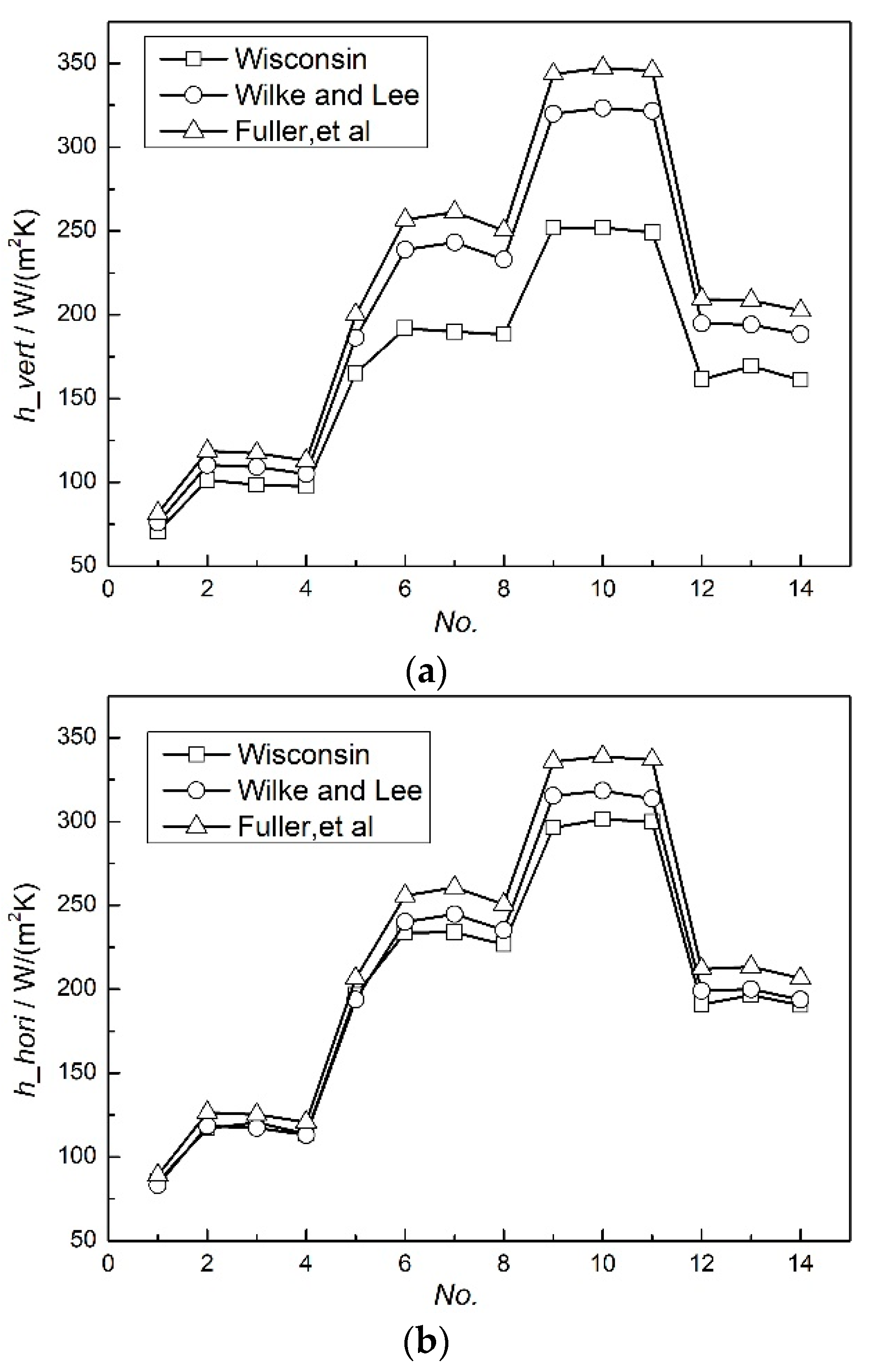
By selecting two different binary mass diffusivity calculation models, the final heat transfer coefficient obtained from the code was compared with the experimental data from the Wisconsin condensation heat transfer experiment, as shown in Figure 4. The results show that although there is a significant difference between the condensation heat transfer coefficient calculated using the code and the experimental data, the results calculated using different mass diffusivity models are indeed different, and the deviation is about 5–10%. The results from the Wilke and Lee model were significantly closer to the experimental data than those from the Fuller model, indicating that physical parameters have an effect on the accuracy of the calculated results.

4.3. Condensation Model

The condensation phenomenon of steam containing noncondensable gas plays an important role in the heat removal process of the containment in a nuclear power plant under an accident condition. As can be seen from Equation (2), the total heat transfer coefficient is affected by both the convective heat transfer coefficient and the condensation heat transfer coefficient, and there are certain differences in the calculation results obtained using the different condensation calculation models. So, it is important to select an accurate condensation model that is suitable for the development of a severe accident analysis code. In this paper, the most widely used experimental correlation models of Uchida [7], Tagami [8] and Dehbi [
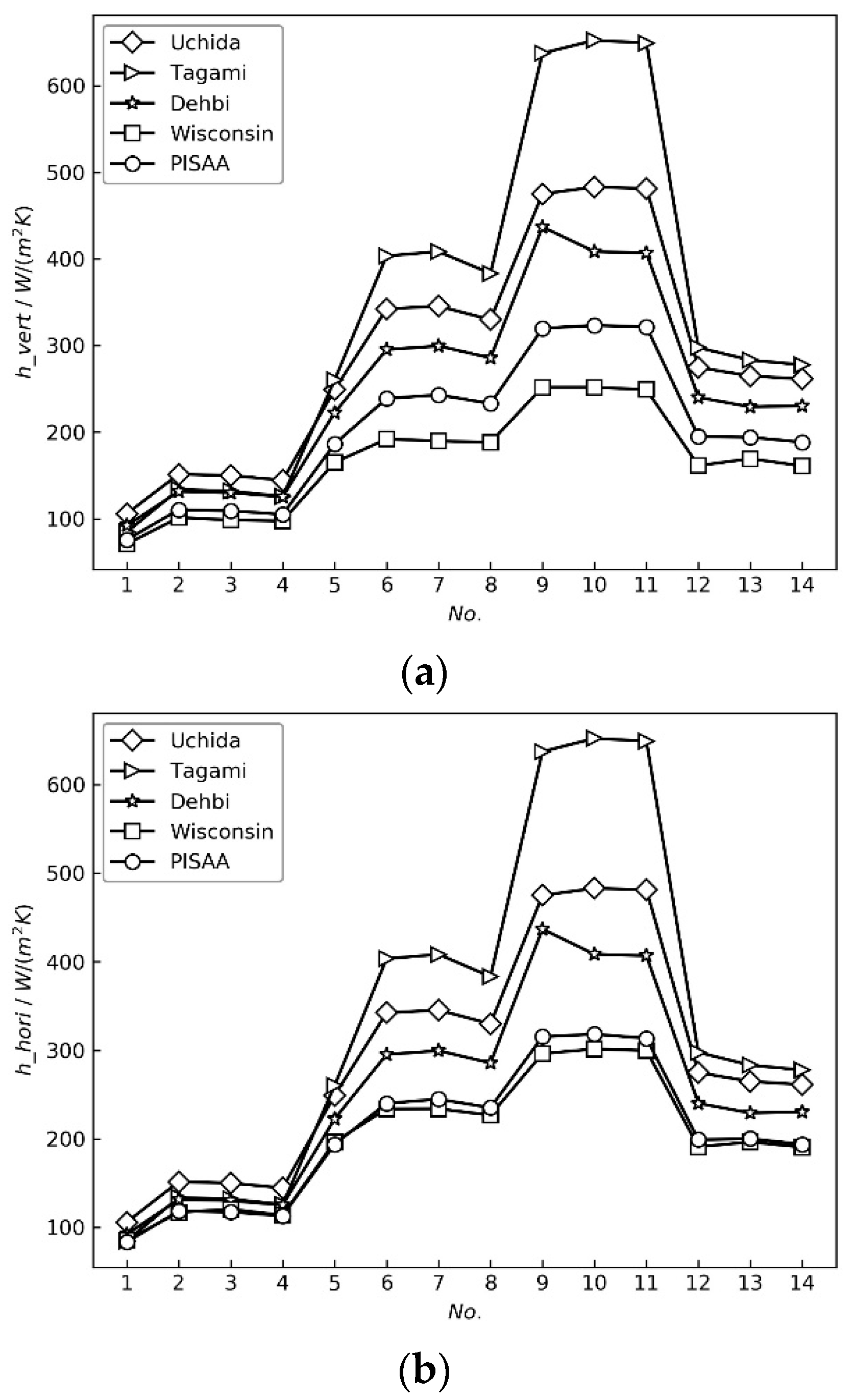
9] are selected successively to compare with the experimental results and the calculated values of the PISAA code model.
h Uchida = 380.0 ( W nc 1 W nc ) 0.7
h Tagami = 11.4 + 284 ( 1 x nc x nc )
h Dehbi = L 0.05 [ 3.7 + 28.7 p ( 2483 + 458.3 p ) log 10 W nc ] ( T g T w ) 0.25
where: h—condensing heat transfer coefficient; Wnc—noncondensable gas mass fraction; xnc—noncondensable gas volume fraction; L—characteristic length of condensing wall; p—pressure; Tg—gas temperature; Tw—condensing wall temperature.
The comparison results are shown in the Figure 5.
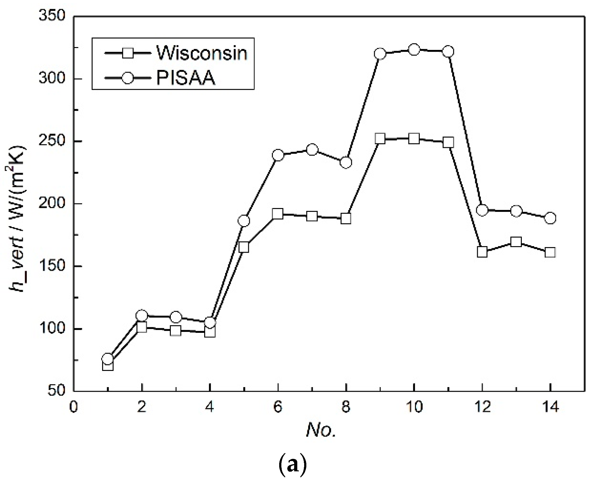
The comparison shows that the calculation results of the condensation model based on Fick’s law and the heat/mass transfer analogy principle chosen in this paper are closer to the experimental measurement data from the Wisconsin experiment. The deviation between the calculation results from the Tagami model and the experimental data is the largest, and the accuracy of the Dehbi model is slightly higher than that of Tagami and Uchida, but the deviation is much larger than that of the calculation model used in this paper.
To analyze the reason, the Uchida and Tagami models only consider the influence of the noncondensable gas fraction on the condensation heat transfer coefficient, and the Dehbi model is further improved, considering the influences of wall length, total pressure and wall subcooling degree on the condensation heat transfer coefficient, but the applicability range of the model is limited, and the factors affecting the mass and heat transfer of condensation, such as the temperature and composition of the gas in the main flow and the interface, are not considered in detail. The calculation model used in the PISAA code considers all the factors mentioned above; therefore, the calculation results are closer to the actual experimental measurements, and at the same time, simulate better.
The comparison results show that the condensation heat transfer model used in this paper, which is based on simplifying and integrating the mechanism and the experimental correlations, can effectively solve the limitations of the traditional empirical correlations model, and realize the accurate simulation of the condensation heat transfer of steam with noncondensable gas, and the calculation results are more reliable than the results calculated using the pure empirical correlations.

5. Conclusions

Based on the law of energy conservation and the thermal resistance relationship of each heat transfer process, combined with the mechanism and experimental correlations, this paper integrates a comprehensive calculation model of the condensation heat transfer of steam with noncondensable gas, including convection heat transfer, liquid film heat transfer and steam condensation heat transfer, and also considers the influence of various factors such as the condensation amount and flow patten classification in the liquid film on the process. The total heat transfer coefficient is obtained via the iterative method, the model is more applicable under different conditions and the calculated results are closer to the experimental data.
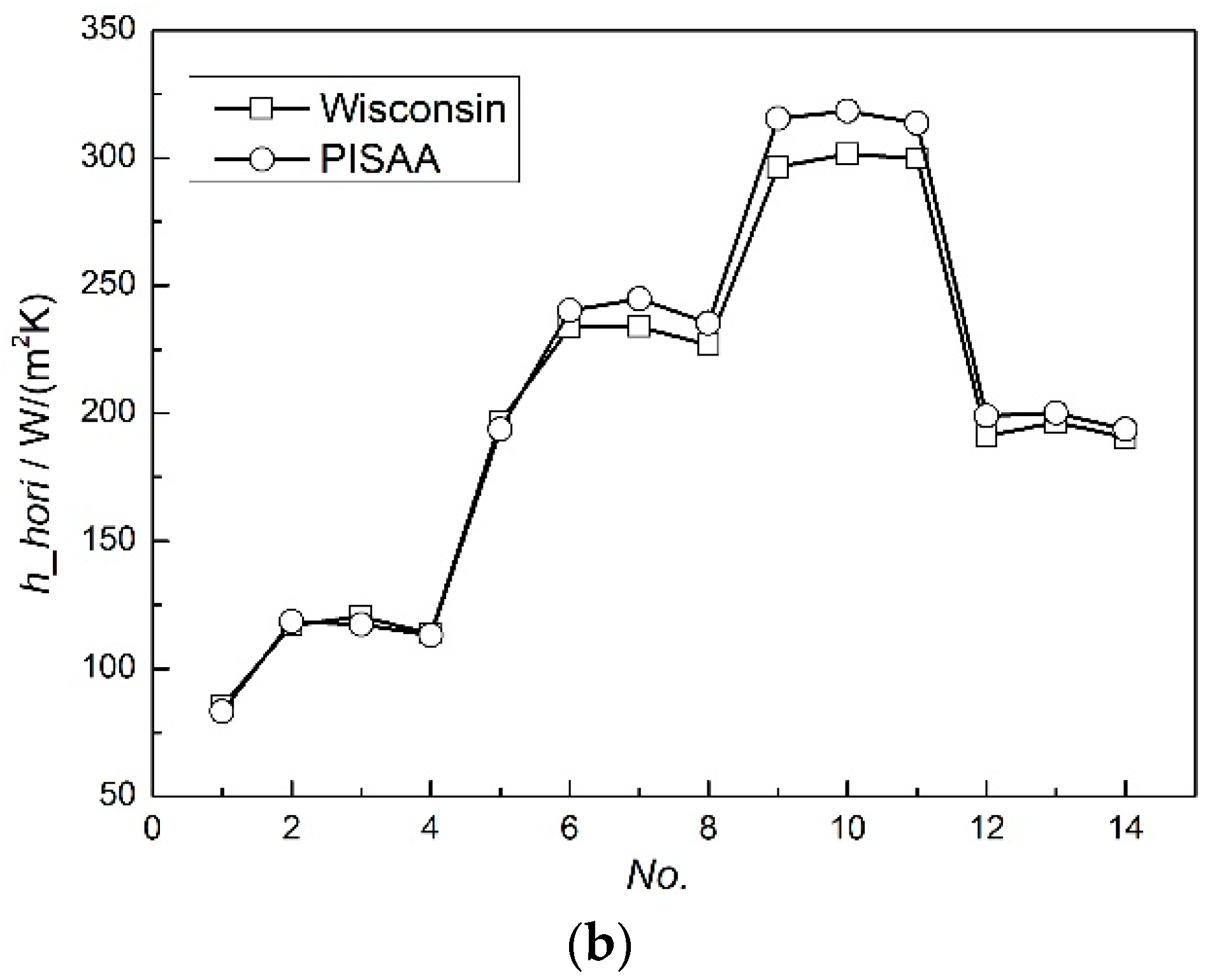
The condensation model is then used in an analysis code, PISAA, and the model is verified by comparing the calculation results with those from traditional containment analysis codes towards the same example, the change trend is basically consistent and the final steady-state values are only in a small variation range. And in the calculation and validation of the condensation heat transfer experiment in Wisconsin using the PISAA software, the average deviation of the heat transfer coefficient of the horizontal condensation heat transfer is 2.55%, and the maximum calculation deviation of the vertical condensing plate is about 29%, which is within the acceptable range of engineering. The reason for the large deviation may be that the simplified method of condensate film thickness in the vertical wall is not consistent with the actual situation, which can be further optimized and improved in the future.
Through the analysis of the sensitive parameters affecting the heat transfer coefficient, the division of the nodes on the condensing plate is less, that is, the temperature distribution has a little affect on the heat transfer coefficient. For the mass diffusivity calculation model, the maximum deviations between the calculated results obtained using the Wilke and Lee models and the Fuller model and the experimental values are 29% and 36%, respectively, and the physical property parameters affect the accuracy of the calculated results to some extent.
The deviations from different condensation models’ calculated results and the experimental data are much larger than that of the condensation model used in this paper, indicating that the model is scientific and reasonabl, and can be used for thermal hydraulic analysis in a nuclear power plant.
The prototypes of the calculation equations in this paper come from the existing experimental data and references, and are simplified according to the theory and practical situation, integrated and coupled together in the calculation code, PISAA, which solves the problem of calculating the condensation of high-temperature and high-pressure gas in the containment in a nuclear power plant under a severe accident scenario, and has great significance for the accident analysis and simulation of a nuclear power plant and the improvement in the nuclear power safety level.

Author Contributions

Conceptualization, Y.Y. and X.Y.; methodology, X.Y. and R.M.; software, H.L. and S.S.; formal analysis, C.W.; investigation, H.L.; writing—original draft preparation, H.L. and S.S.; writing—review and editing, H.L. and C.W.; supervision, R.M.; project administration, Y.Y. All authors have read and agreed to the published version of the manuscript.

Funding

This research was funded by the National Key R&D Program of China (2019YFB1900704) grant, number 2.2 million.

Institutional Review Board Statement

Not applicable.

Informed Consent Statement

Not applicable.

Data Availability Statement

The data presented in this study are available upon request from the corresponding authors.

Conflicts of Interest

The authors declare no conflict of interest.

Nomenclature

Ttemperature, K
qheat flux, W/m2
hheat transfer coefficient, W/(m2 K)
Ddiffusion coefficient, m2/s
Mmolar mass, kg/mol
Rgas constant, J/(mol K)
kthermal conductivity, W/(m K)
ScSchmidt number
PrPrandtl number
Xgas volume fraction, %
Lcharacteristic length, m
Wmass fraction, %
ggas
lliquid
steamsteam
wwall
ncnoncondensable gas

References

  1. Dela, R.J.; Escriva, A.; Herranz, L.E.; Cicero, T.; Munoz-Cobo, J.L. Review on condensation on the containment structures. Prog. Nucl. Energy 2009, 51, 32–66. [Google Scholar]
  2. Yadav, M.K.; Khandekar, S.; Sharma, P.K. An integrated approach to steam condensation studies inside reactor containments: A review. Nucl. Eng. Des. 2016, 300, 181–209. [Google Scholar]
  3. Huang, J.; Zhang, J.X.; Wang, L. Review of vapor condensation heat and mass transfer in the presence of non-condensable gas. Appl. Therm. Eng. 2015, 89, 469–484. [Google Scholar] [CrossRef]
  4. Su, J.Q.; Fan, L.; Gao, L. Review of steam condensation heat transfer under containment cooling system condition. At. Energy Sci. Technol. 2016, 50, 1956–1966. [Google Scholar]
  5. Colburn, A.P.; Hougen, O.A. Design of cooler condensers for mixtures of vapors with noncondensing gases. Ind. Eng. Chem. 1934, 26, 1178–1182. [Google Scholar] [CrossRef]
  6. Hasson, D.; Luss, D.; Navon, U. An experimental study of steam condensation on a laminar water sheet. Int. J. Heat Mass Transf. 1964, 7, 983–1001. [Google Scholar] [CrossRef]
  7. Uchida, H.; Oyama, A.; Togo, Y. Evaluation of Post—Incident Cooling Systems of Light Water Power Reactors. In Proceedings of the Third International Conference on the Peaceful Uses of Atomic Energy, Geneva, Switzeland, 31 August–9 September 1964. [Google Scholar]
  8. Tagami, T. Interim Report on Safety Assessments and Facilities Establishment Project for June 1965; Japanese Atomic Energy Research Agency: Tokyo, Japan, 1965. [Google Scholar]
  9. Dehbi, A.A. The Effects of Noncondensable Gases on Steam Condensation under Turbulent Natural Convection Conditions; Massachusetts Institute of Technology: Cambridge, MA, USA, 1991. [Google Scholar]
  10. Fan, G.M.; Tong, P.; Sun, Z.N.; Chen, Y. Development of a new empirical correlation for steam condensation rates in the presence of air outside vertical smooth tube. Ann. Nucl. Energy 2018, 113, 139–146. [Google Scholar] [CrossRef]
  11. Bhowmik, P.K.; Schlegel, J.P.; Revankar, S. State-of-the-art and review of condensation heat transfer for small modular reactor passive safety: Experimental studies. Int. J. Heat Mass Transf. 2022, 192, 122936. [Google Scholar] [CrossRef]
  12. Murase, M.; Kataoka, Y.; Fujii, T. Evaporation and condensation heat transfer with a non-condensable gas present. Nucl. Eng. Des. 1993, 141, 135–143. [Google Scholar] [CrossRef]
  13. Ambrosini, W.; Forgione, N.; Manfredini, A.; Oriolo, F. On various forms of the heat and mass transfer analogy: Discussion and application to condensation experiments. Nucl. Eng. Des. 2006, 236, 1013–1027. [Google Scholar] [CrossRef]
  14. Oh, S.; Revankar, S.T. Experimental and theoretical investigation of film condensation with noncondensable gas. Int. J. Heat Mass Transf. 2006, 49, 2523–2534. [Google Scholar] [CrossRef]
  15. Anderson, M.H. Steam Condensation on Cold Walls of Advanced PWR Containments. Ph.D. Thesis, The University of Wisconsin, Madison, WI, USA, 1998. [Google Scholar]
  16. Zhang, L.L.; Zhang, G.M.; Tian, M.C.; Zhang, J.; Zhang, Y. Modeling of laminar filmwise condensation of methane with nitrogen on an isothermal vertical plate. Int. Commun. Heat Mass Transf. 2019, 105, 10–18. [Google Scholar] [CrossRef]
  17. Wang, T.L.; Wang, D.; Tong, L.L.; Cao, X. Improvement of Condensation Model With the Presence of Non-Condensable Gas for Thermal-Hydraulic Analysis in Containment. Front. Energy Res. 2021, 9, 671539. [Google Scholar] [CrossRef]
  18. Hammoudi, D.; Benabdesselam, A.; Azzi, A.; Kassim, M.A. Numerical modeling of steam condensation in vertical channel in presence of noncondensable gas. Int. J. Therm. Sci. 2018, 126, 263–271. [Google Scholar] [CrossRef]
  19. Li, S.W.; Wei, M.; Wang, X.J. A numerical study on film condensation of steam with non-condensable gas on a vertical plate. Front. Energy Res. 2023, 11, 1064067. [Google Scholar] [CrossRef]
  20. Vyskocil, L.; Schmid, J.; Macek, J. CFD simulation of air–steam flow with condensation. Nucl. Eng. Des. 2014, 279, 147–157. [Google Scholar] [CrossRef]
  21. Punetha, M.; Khandekar, S. A CFD based modelling approach for predicting steam condensation in the presence of non-condensable gases. Nucl. Eng. Des. 2017, 324, 280–296. [Google Scholar] [CrossRef]
  22. Liu, F.; Sun, Z.N.; Cao, B.Y.; Bian, H.; Ding, M. Numerical investigations on the component separation phenomenon and transport behavior of steam-air-hydrogen mixture induced by condensation. Int. J. Therm. Sci. 2022, 172, 107369. [Google Scholar] [CrossRef]
  23. Wen, J.; Liang, M.Z.; Zhang, H.W.; Cheng, X.H. Numerical simulation of steam condensation in vertical tube with the presence of non-condensable gas. J. Shanghai Jiaotong Univ. 2009, 43, 299–303. [Google Scholar]
  24. Sun, S.H.; Li, S.G.; Shaheen, S.; Arain, M.B.; Usman; Khan, K.A. A numerical investigation of bio-convective electrically conducting water-based nanofluid flow on the porous plate with variable wall temperature. Numer. Heat Transf. Part A Appl. 2023, 1–15. [Google Scholar] [CrossRef]
  25. Peng, X.; Cao, X.X.; Cao, J.H.; Ding, M.; Bian, H. Numerical study on the effect of CO2 on the heat transfer characteristics of steam condensation outside a vertical tube. Nucl. Eng. Des. 2022, 391, 111745. [Google Scholar] [CrossRef]
  26. Ma, X.Z. Research on Steam Condensation with non -Condensable Gases under the High Pressure. Ph.D. Thesis, Tsinghua University, Beijing, China, 2017. [Google Scholar]
  27. Ganguli, A.; Patel, A.G.; Maheshwari, N.K.; Pandit, A.B. Theoretical modeling of condensation of steam outside different vertical geometries (tube, flat plates) in the presence of non-condensable gases like air and helium. Nucl. Eng. Des. 2008, 238, 2328–2340. [Google Scholar] [CrossRef]
  28. Liu, Z.; Jin, H.X.; Li, X.Y.; Wu, X. Research on condensation heat transfer in the presence of noncondensable gases based on Fick’s law and HMTA. Nucl. Saf. 2017, 16, 85–90. [Google Scholar]
  29. Bergman, T.L.; Lavine, A.S.; Frank, P.; DeWitt, D.P. Fundamentals of Heat and Mass Transfer, 7th ed.; John Wiley & Sons: Hoboken, NJ, USA, 2011. [Google Scholar]
  30. Bruce, E.P.; John, M.P.; John, P.O. The Proper Ties of Gases and Liquids, 5th ed.; The McGraw-Hill Companies, Inc.: New York, NY, USA, 2001. [Google Scholar]
Figure 1. Condensation model of steam with noncondensable gas on vertical wall.
Applsci 13 10520 g001
Figure 2. Comparison of calculation results of control volume coupled heat structure. (a) Pressure. (b) Gas temperature. (c) Wall heat transfer coefficient. (d) Wall temperature.
Applsci 13 10520 g002aApplsci 13 10520 g002b
Figure 3. Comparison of condensation heat transfer coefficient between experimental data and calculation result. (a) Vertical condensing wall. (b) Horizontal condensing wall.
Applsci 13 10520 g003aApplsci 13 10520 g003b
Figure 4. Influence of mass diffusivity model on condensation heat transfer coefficient. (a) Vertical condensing wall. (b) Horizontal condensing wall.
Applsci 13 10520 g004
Figure 5. Effect of condensation model on heat transfer coefficient of condensation. (a) Vertical condensation wall. (b) Horizontal condensation wall.
Applsci 13 10520 g005
Table 1. Initial testing conditions of control volume coupled with heat structure.
ParametersValue
Volume (m3)1000
Elevation (m)0.0
Control volume height (m)15.0
Hydraulic diameter (m)9.2132
Pressure (kPa)101.0
Gas phase temperature (K)313.15
Liquid phase temperature (K)-
Relative humidity (%)0.1
Liquid phase fraction (%)0.0
Surface area (m2)552.0
Elevation (m)0.0
Heat structure height (m)5.0
Thickness (m)0.3048
DirectionVertical
Boundary condition AConvective
Boundary condition BConvective
Initial temperature (K)353.15
Calculation time (s)15,000.0
Table 2. Initial condition of condensation heat transfer.
No.Pressure (kPa)Molar Fraction of Noncondensable Gas (%)Wall Temperature (°C)Gas Temperature (°C)
1100.00.79528.6060.65
2100.00.69929.4069.23
3100.00.70229.4069.04
4100.00.71329.2068.15
5100.00.53334.0079.68
6100.00.42028.4385.12
7100.00.41729.7685.25
8100.00.43329.4784.55
9100.00.31230.6089.53
10100.00.30730.3089.72
11100.00.30829.9689.68
12100.00.49827.7681.46
13100.00.51131.7480.80
14100.00.51629.5880.58
Table 3. Influence of the number of nodes on heat transfer coefficient for a vertical condensing plate.
No.Wisconsin2 Nodes5 Nodes10 Nodes
170.875.8777775.8793375.8811
2101.38110.402110.4073110.413
398.47109.2021109.2072109.212
497.52105.0613105.0658105.071
5165.07186.3355186.3552186.374
6191.92238.8905238.9315238.97
7189.88243.1433243.1854243.225
8188.22232.9544232.9926233.028
9251.88319.8702319.9486320.021
10251.89323.3353323.4157323.491
11249.07321.6682321.7479321.822
12161.42194.8331194.8586194.883
13169.34194.1343194.1583194.181
14161.015188.3783188.4013188.423
Table 4. Influence of the number of nodes on heat transfer coefficient for a horizontal condensing plate.
No.Wisconsin2 Nodes5 Nodes10 Nodes
185.2883.303383.3057583.3083
2116.935118.4498118.4575118.4649
3120.45117.2453117.2528117.26
4113.645113.0738113.0805113.0871
5196.605193.7196193.7462193.7713
6233.79240.1341240.1856240.2329
7233.895244.776244.8291244.8777
8226.695235.2196235.268235.3124
9296.38315.387315.4822315.5691
10301.405318.3065318.4039318.493
11299.725313.5457316.6421316.7304
12190.97199.0317199.0647199.0952
13196.47200.126200.1576200.1863
14190.47193.7491193.7791193.8068
Disclaimer/Publisher’s Note: The statements, opinions and data contained in all publications are solely those of the individual author(s) and contributor(s) and not of MDPI and/or the editor(s). MDPI and/or the editor(s) disclaim responsibility for any injury to people or property resulting from any ideas, methods, instructions or products referred to in the content.

